EP3321944B1 - Bombardment-resistant electrical installation - Google Patents
Bombardment-resistant electrical installation Download PDFInfo
- Publication number
- EP3321944B1 EP3321944B1 EP17001864.2A EP17001864A EP3321944B1 EP 3321944 B1 EP3321944 B1 EP 3321944B1 EP 17001864 A EP17001864 A EP 17001864A EP 3321944 B1 EP3321944 B1 EP 3321944B1
- Authority
- EP
- European Patent Office
- Prior art keywords
- boiler
- transformer
- panels
- bullet
- side walls
- Prior art date
- Legal status (The legal status is an assumption and is not a legal conclusion. Google has not performed a legal analysis and makes no representation as to the accuracy of the status listed.)
- Active
Links
- 238000010616 electrical installation Methods 0.000 title claims 2
- 239000000463 material Substances 0.000 claims description 13
- 230000000694 effects Effects 0.000 claims description 4
- 239000012530 fluid Substances 0.000 claims description 4
- 239000012634 fragment Substances 0.000 claims description 4
- 230000002787 reinforcement Effects 0.000 description 11
- 230000001681 protective effect Effects 0.000 description 10
- 229910000831 Steel Inorganic materials 0.000 description 8
- 239000010959 steel Substances 0.000 description 8
- 238000001816 cooling Methods 0.000 description 6
- 238000012360 testing method Methods 0.000 description 6
- 239000007788 liquid Substances 0.000 description 5
- 239000004033 plastic Substances 0.000 description 5
- 229920003023 plastic Polymers 0.000 description 5
- 239000002360 explosive Substances 0.000 description 4
- 229920006231 aramid fiber Polymers 0.000 description 3
- 238000010276 construction Methods 0.000 description 3
- 230000001066 destructive effect Effects 0.000 description 3
- 238000013467 fragmentation Methods 0.000 description 3
- 238000006062 fragmentation reaction Methods 0.000 description 3
- 229920000049 Carbon (fiber) Polymers 0.000 description 2
- 229920000271 Kevlar® Polymers 0.000 description 2
- 239000004698 Polyethylene Substances 0.000 description 2
- 239000004760 aramid Substances 0.000 description 2
- 239000004917 carbon fiber Substances 0.000 description 2
- 238000006243 chemical reaction Methods 0.000 description 2
- 239000002184 metal Substances 0.000 description 2
- 239000007769 metal material Substances 0.000 description 2
- 230000035515 penetration Effects 0.000 description 2
- -1 polyethylene Polymers 0.000 description 2
- 229920000573 polyethylene Polymers 0.000 description 2
- 229920000642 polymer Polymers 0.000 description 2
- 239000002861 polymer material Substances 0.000 description 2
- 229920000784 Nomex Polymers 0.000 description 1
- 229910000639 Spring steel Inorganic materials 0.000 description 1
- 239000002131 composite material Substances 0.000 description 1
- 238000013016 damping Methods 0.000 description 1
- 238000004880 explosion Methods 0.000 description 1
- 239000000835 fiber Substances 0.000 description 1
- 239000007789 gas Substances 0.000 description 1
- 238000012812 general test Methods 0.000 description 1
- 230000001771 impaired effect Effects 0.000 description 1
- 239000011261 inert gas Substances 0.000 description 1
- 230000002401 inhibitory effect Effects 0.000 description 1
- 238000009434 installation Methods 0.000 description 1
- 239000004761 kevlar Substances 0.000 description 1
- 238000004519 manufacturing process Methods 0.000 description 1
- 239000002905 metal composite material Substances 0.000 description 1
- VNWKTOKETHGBQD-UHFFFAOYSA-N methane Chemical compound C VNWKTOKETHGBQD-UHFFFAOYSA-N 0.000 description 1
- 239000004763 nomex Substances 0.000 description 1
- 229910052755 nonmetal Inorganic materials 0.000 description 1
Images

Classifications
-
- H—ELECTRICITY
- H02—GENERATION; CONVERSION OR DISTRIBUTION OF ELECTRIC POWER
- H02B—BOARDS, SUBSTATIONS OR SWITCHING ARRANGEMENTS FOR THE SUPPLY OR DISTRIBUTION OF ELECTRIC POWER
- H02B1/00—Frameworks, boards, panels, desks, casings; Details of substations or switching arrangements
- H02B1/26—Casings; Parts thereof or accessories therefor
- H02B1/46—Boxes; Parts thereof or accessories therefor
-
- H—ELECTRICITY
- H01—ELECTRIC ELEMENTS
- H01F—MAGNETS; INDUCTANCES; TRANSFORMERS; SELECTION OF MATERIALS FOR THEIR MAGNETIC PROPERTIES
- H01F27/00—Details of transformers or inductances, in general
- H01F27/02—Casings
-
- F—MECHANICAL ENGINEERING; LIGHTING; HEATING; WEAPONS; BLASTING
- F41—WEAPONS
- F41H—ARMOUR; ARMOURED TURRETS; ARMOURED OR ARMED VEHICLES; MEANS OF ATTACK OR DEFENCE, e.g. CAMOUFLAGE, IN GENERAL
- F41H5/00—Armour; Armour plates
- F41H5/02—Plate construction
- F41H5/023—Armour plate, or auxiliary armour plate mounted at a distance of the main armour plate, having cavities at its outer impact surface, or holes, for deflecting the projectile
-
- F—MECHANICAL ENGINEERING; LIGHTING; HEATING; WEAPONS; BLASTING
- F41—WEAPONS
- F41H—ARMOUR; ARMOURED TURRETS; ARMOURED OR ARMED VEHICLES; MEANS OF ATTACK OR DEFENCE, e.g. CAMOUFLAGE, IN GENERAL
- F41H5/00—Armour; Armour plates
- F41H5/24—Armour; Armour plates for stationary use, e.g. fortifications ; Shelters; Guard Booths
-
- H—ELECTRICITY
- H01—ELECTRIC ELEMENTS
- H01F—MAGNETS; INDUCTANCES; TRANSFORMERS; SELECTION OF MATERIALS FOR THEIR MAGNETIC PROPERTIES
- H01F27/00—Details of transformers or inductances, in general
- H01F27/02—Casings
- H01F27/022—Encapsulation
-
- H—ELECTRICITY
- H01—ELECTRIC ELEMENTS
- H01F—MAGNETS; INDUCTANCES; TRANSFORMERS; SELECTION OF MATERIALS FOR THEIR MAGNETIC PROPERTIES
- H01F27/00—Details of transformers or inductances, in general
- H01F27/08—Cooling; Ventilating
- H01F27/10—Liquid cooling
- H01F27/12—Oil cooling
-
- H—ELECTRICITY
- H02—GENERATION; CONVERSION OR DISTRIBUTION OF ELECTRIC POWER
- H02B—BOARDS, SUBSTATIONS OR SWITCHING ARRANGEMENTS FOR THE SUPPLY OR DISTRIBUTION OF ELECTRIC POWER
- H02B1/00—Frameworks, boards, panels, desks, casings; Details of substations or switching arrangements
- H02B1/56—Cooling; Ventilation
-
- H—ELECTRICITY
- H03—ELECTRONIC CIRCUITRY
- H03H—IMPEDANCE NETWORKS, e.g. RESONANT CIRCUITS; RESONATORS
- H03H7/00—Multiple-port networks comprising only passive electrical elements as network components
- H03H7/18—Networks for phase shifting
-
- H—ELECTRICITY
- H05—ELECTRIC TECHNIQUES NOT OTHERWISE PROVIDED FOR
- H05K—PRINTED CIRCUITS; CASINGS OR CONSTRUCTIONAL DETAILS OF ELECTRIC APPARATUS; MANUFACTURE OF ASSEMBLAGES OF ELECTRICAL COMPONENTS
- H05K5/00—Casings, cabinets or drawers for electric apparatus
Definitions
- the invention generally relates to the technical field of electrical systems, in particular electrical transformers, phase shifters and chokes of large rated power, such as are usually used in power distribution networks.
- Electrical systems such as transformers, chokes or switching devices represent nodes in a power distribution network that can be potential targets for destructive attacks from outside in times of crisis.
- Such attacks are, for example, attacks from the surrounding terrain by small arms fire, by explosive devices detonated near the electrical system, or by grenade and bomb splinters.
- the side walls of a tank filled with a fluid are particularly vulnerable. When a round hits these side walls, depending on the intensity of the bullet impact, a leak can occur. But even if the boiler remains tight, a pressure wave can propagate in a liquid-filled boiler, causing safety devices to switch off the system. In both cases, the energy supply can be affected by the attack.
- the DE 100 02 630 A1 relates to a substation with a cast body made of concrete, which has, among other things, a space for a medium-voltage transformer.
- This concrete building is equipped with a reinforcement made of a material with high tensile strength.
- the DE 37 29 048 A1 relates to a transformer with a transformer tank, the side walls of which are reinforced on the inside by protective plates. These protective plates are made of special steel and are used to intercept grenade or bomb splinters.
- the DE 36 33 349 A1 concerns a bullet-resistant conversion element for the protection of industrial plants.
- This conversion element has a flat sheet steel outer wall which, despite its simple structure, has a high resistance to projectiles.
- a sheet steel inner wall is also provided, with sheet steel intermediate walls also being disclosed.
- object protection for a transformer with a large nominal power in which the side walls of the transformer tank are reinforced on the inside with protective plates to protect against external mechanical influences.
- the protective plates are welded to the inside of the side walls and are made of a special steel to catch splinters and projectiles.
- a disadvantage is that the protective armor is weakened in the area of the weld.
- Another disadvantage is that in the event of a decision, pressure waves propagate in the liquid-filled tank, which can lead to safety devices switching off the transformer. The power supply is then interrupted at least temporarily.
- the ballistic resistance can thus be achieved in that at least the side walls of the tank are made, for example, from a steel with a tensile strength R m of more than 1000 MPa.
- the tensile strength of materials is defined in DIN EN ISO 6892-1.
- object protection is achieved by a bullet-resistant design of the boiler.
- the fluid in the boiler can be a cooling or insulating liquid, e.g. transformer oil, or a gas in a switchgear.
- test level 1 begins with a caliber of .22 Ir, a projectile mass of 2.6 g and a projectile energy of around 160 J (joules).
- Test stage 14 includes a caliber of 14.5 x 114, a bullet mass of around 64 g and a bullet energy of 26308 J (joules).
- the protective measure according to the invention comprises at least one area of action specified in the standards specified above. In other words, shelling in such an area will not cause a leak in the electrical system boiler.
- a protective measure within this effective range (level 1 to 10, or test level 1-14) can be implemented with reasonable effort. In principle, an electrical system can also be protected against bullets beyond this effective range.
- a material is used for the protective measure that has a tensile strength Rm that is greater than 1000 MPa (Mega Pascal).
- a high tensile strength makes the material particularly suitable for reinforcement or armouring.
- Such a material with high tensile strength can be a metallic or non-metallic material, for example a polymer material, a plastic reinforced with carbon fibers, a material based on polyethylene, or aramid fibers.
- aramid fibers are, for example, Nomex ® and Kevlar ® from DuPont.
- the plastic fibers can be woven and knit together in different ways.
- a sandwich construction made of a composite consisting of metal and non-metal (a plastic, a carbon fiber fleece or similar) is in principle suitable as a material for the bullet-resistant reinforcement.
- the advantage of a polymer is its comparatively lower weight, which is offset by the higher costs.
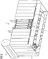
- the figure 1 shows a bullet-proof electrical system in a perspective view, shown using the example of a power transformer 1.
- the power transformer 1 stands on a foundation that is not shown in detail.
- the bulletproof armor or armor 4 encloses the side walls of the power transformer 1 and protrudes into the floor area.
- the armor 4 is constructed in terms of its nature and dimensions in such a way that it withstands a threat of fire or shrapnel from the surrounding terrain, so that all parts of the system are protected.
- this reinforcement or armor 4 from individual plates or panels 7, which form a vertical protective wall.
- This lined-up plates 7 enclose the system 1 all around. They form a protective shell that protects against bullets and fragments.
- the individual panels 7 are made from sheet steel, the tensile strength of which is R m >1000 Mega Pascal.
- the sheet thickness depends on the desired rating (UL 752) or the test level (VPAM APR 2006).
- the length of the individual panels 7 is dimensioned in such a way that shelling or fragmentation from the surrounding terrain cannot damage either the transformer 1 or the system parts located on the boiler cover. As in figure 1 shown, the upper end of the individual panels 7 therefore protrudes beyond the system components arranged on the boiler cover, such as lower parts of high-voltage bushings and domes 10 or other system parts of the power transformer 1.
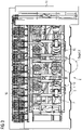
- figure 2 shows the in figure 1 illustrated power transformer 1 also in a perspective view, but this time looking from behind and diagonally below.
- the power transformer 1 has a radiator 16 on a longitudinal side wall to dissipate the operating heat.
- the view is in figure 2 directed at this radiator 16 from obliquely below.
- the radiator 16 is also armored on the outside and protected from destructive side effects.
- a vertical cooling duct is left open in the area of the radiator 16, but this is also shielded on the outside by panels 7 in a bulletproof or shatterproof manner.
- figure 3 shows the power transformer 1 according to FIG figure 1 in a top view.
- the radiator 16 is located on a long side wall of the transformer 1.
- the connection to the power supply network takes place via high-voltage bushings and domes 10 which are arranged on the roof of boiler 2.
- the bellows 15 has the shape of a cylinder.
- the lateral surface of the expansion vessel 15 is approximately parallel to the boiler lid level.
- One end of the cylinder projects laterally from the plan of the transformer tank.
- This armor 4 can also be made up of individual panels 7 .
- the panels 7 are arranged vertically and horizontally here.
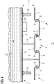
- FIG 4 shows a detail X of the figure 3 in an enlarged view.
- a preferred profiling and arrangement of the individual panels 7 is drawn as an example.
- the panels 7 are arranged vertically next to one another.
- the panels 7 overlap each other laterally.
- Each panel 7 is connected to the boiler 2 or to a side wall 3 of the boiler 2 by means of a plurality of fastening elements 5 .
- the attachment can either be anchored directly to the boiler wall 3 or to ribs or reinforcements 19 of the boiler 2.
- the individual panels 7 of the reinforcement 4 are arranged at a distance 6 around the circumference of the boiler wall 3.
- the fastening elements 5, which are described in more detail below, are located in a circumferential intermediate space 18 which is delimited by the boiler wall 3 and the opposite inner side of the panels 9.
- the panels 7 have the shape of a U-profile in a preferred embodiment, consisting of two leg parts 9 and a connecting part 8.
- the leg parts 9 are bent up with respect to the connecting part 8 connecting them and each enclose an obtuse angle with this connecting part 8.
- the arrangement is selected such that panels 7 lying adjacent to one another are mirror images of one another in terms of their cross section.
- leg parts 9 reach under each other.
- a gap is left.
- the gap and the shape of the bend of the legs 9 are dimensioned in such a way that a kind of labyrinth is formed. In the area of the joint, this labyrinth fends off the penetration of a projectile or fragmentation body fired from the outer space 21 .
- the attachment of the fastening elements 5 ensures that the energy of the projectile is distributed over a number of fastening points.
- Each panel 7 is supported on the boiler 2 by a number of support points.
- the intensity of the pressure wave that propagates in the cooling and insulating liquid 22 in the boiler interior 20 is therefore lower. This can prevent the system from being switched off unintentionally in the event of a decision or an external explosion.
- the supply of electrical energy in a distribution network is maintained in the event of a destructive attack. If the panels are severely damaged, they can be easily replaced.
- a hinge 14 can also be seen, whereby the panel 7' can be pivoted away from the transformer tank 2 according to the arrow.
- This possibility of pivoting one or more of the panels 7′ makes it possible for equipment or add-on parts 23, which are located in the intermediate space 18 between the reinforcement 4 and the boiler wall 3, to be accessible from the outside.
- Such an operating means 23 can be a display, switching or connection device.
- a panel 7 can have a width of 20 cm up to the range of meters.
- the hinge 17 can extend over the entire height or only over a height section.
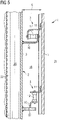
- the figure 5 shows a possible embodiment of the fastening device 5 of the panels 7 on the boiler 2.
- the panels 7 are fixed at a distance 6 with respect to the boiler wall 3 vertically. Between the boiler wall 2 and a panel 7 there is a gap 18.
- a fastening with two fastening elements 5 is shown as an example.
- the top and the lower fastening element 5 essentially consists of a metal-rubber-metal component which is fastened to the boiler wall 2 and the panel 7 by means of a bracket 10 on the boiler side and a bracket 11 on the panel side.
- the upper fastening body 5 is arranged horizontally and the lower fastening body 5 is arranged vertically.
- each panel 7 can be fasten to the boiler 2 with a number of fastening points.
- the reinforcements or ribs already present on the boiler 2 can be used or shared for fastening. Suitable fastening options can preferably already be provided during the production of the boiler by means of a welded connection.
- a panel 7 consists of a single steel sheet with a high tensile strength.
- non-metallic materials can also be used to keep the boiler away from bullets or explosives. It is conceivable that the panels 7 are sandwich panels or are made of a plastic-metal composite material.
- the armor 7 only a polymer material is used, for example consists of individual plastic panels 7. This makes the Armor 4 lightweight, but also more expensive.
- the plastic panels 7 are made from the aramid fiber Kevlar® , or a high-performance polyethylene (HPDE) or another suitable polymer.
- the invention is not limited to the power transformer described above, but can be applied generally to electrical systems in power supply networks, for example high-voltage switches or similar systems operated with inert gas.
Description
Die Erfindung betrifft allgemein das technische Gebiet elektrischer Anlagen, insbesondere elektrische Transformatoren, Phasenschieber und Drosseln großer Nennleistung, wie Sie üblicherweise in Energieverteilungsnetzen eingesetzt werden.The invention generally relates to the technical field of electrical systems, in particular electrical transformers, phase shifters and chokes of large rated power, such as are usually used in power distribution networks.
Elektrische Anlagen, wie Transformatoren, Drosseln oder Schaltvorrichtungen, stellen in einem Energieverteilungsnetz Knotenpunkte dar, die in Krisenzeiten potentielle Angriffsziele für zerstörerische Anschläge von außen sein können. Solche Anschläge sind beispielsweise Angriffe aus umgebendem Terrain durch Beschuss mit Handfeuerwaffen, durch Sprengsatz, der in der Nähe der elektrischen Anlage detoniert, oder auch durch Granat- und Bombensplitter. Besonders verwundbar sind dabei die Seitenwände eines mit einem Fluid gefüllten Kessel. Wenn ein Beschuss auf diese Seitenwände auftrifft, kann - je nach Intensität der Geschosseinwirkung - ein Leck auftreten. Aber auch dann, wenn der Kessel dicht bleibt, kann sich in einem flüssigkeitsgefüllten Kessel eine Druckwelle fortpflanzen, die Sicherheitseinrichtungen dazu veranlasst, die Anlage abzuschalten. In beiden Fällen kann die Energieversorgung durch den Angriff beeinträchtigt sein.Electrical systems such as transformers, chokes or switching devices represent nodes in a power distribution network that can be potential targets for destructive attacks from outside in times of crisis. Such attacks are, for example, attacks from the surrounding terrain by small arms fire, by explosive devices detonated near the electrical system, or by grenade and bomb splinters. The side walls of a tank filled with a fluid are particularly vulnerable. When a round hits these side walls, depending on the intensity of the bullet impact, a leak can occur. But even if the boiler remains tight, a pressure wave can propagate in a liquid-filled boiler, causing safety devices to switch off the system. In both cases, the energy supply can be affected by the attack.
Die
Die
Die
Weiterer Stand der Technik ist in der
Aus der
Es ist eine Aufgabe der vorliegenden Erfindung eine elektrische Anlage in einem Energieverteilungsnetz, insbesondere einen Transformator oder eine Drossel so zu schützen, dass auch im Falle eines Angriffs mit Handfeuerwaffen oder mit einem Sprengsatz die Energieversorgung nicht beeinträchtigt wird. Gelöst wird diese Aufgabe durch eine elektrische Anlage mit den Merkmalen des Anspruchs 1.It is an object of the present invention to protect an electrical system in a power distribution network, in particular a transformer or a choke, in such a way that in the event of an attack with handguns or an explosive device, the energy supply is not impaired. This problem is solved by an electrical system with the features of
Die vorrichtungsbezogene Aufgabe wird gelöst durch eine elektrische Anlage, insbesondere einem Transformator, einem Phasenschieber oder eine Drossel, mit einem fluidgefüllten Kessel, der Seitenwände aufweist, wobei zum Schutz vor Beschuss- und/oder Splittereinwirkung
- die Seitenwände durchschusshemmend aus einem Werkstoff, der eine Zugefestigkeit Rm aufweist, die größer als 1000 MPa ist, gebildet sind.
- the side walls are made of a bullet-resistant material that has a tensile strength R m that is greater than 1000 MPa.
Die Beschussbeständigkeit kann also erreicht werden, indem zumindest die Seitenwände des Kessels, z.B. aus einem Stahl mit einer Zugefestigkeit Rm von größer als 1000 MPa gefertigt sind.The ballistic resistance can thus be achieved in that at least the side walls of the tank are made, for example, from a steel with a tensile strength R m of more than 1000 MPa.
Die Zugfestigkeit von Materialien ist in DIN EN ISO 6892-1 definiert.The tensile strength of materials is defined in DIN EN ISO 6892-1.
Einem Grundgedanken der Erfindung nach wird also der Objektschutz durch eine durchschusshemmende Ausführung des Kessels erreicht. Das Fluid im Kessel kann eine Kühl- oder Isolationsflüssigkeit sein, z.B. Trafo-Öl, oder ein Gas in einer Schalteranlage.According to a basic idea of the invention, object protection is achieved by a bullet-resistant design of the boiler. The fluid in the boiler can be a cooling or insulating liquid, e.g. transformer oil, or a gas in a switchgear.
Unter dem Begriff beschussbeständig ist die Beständigkeit eines Materials oder einer Konstruktion zu verstehen, einer Durchdringung eines Geschosses unter definierten Bedingungen stand zu halten. Eine Definition der Geschossbeständigkeit ist beispielsweise in der amerikanischen Norm UL 742 (Ratings of Bullet Resistant materials) durch Level 1 bis Level 10 definiert. Korrespondierend hierzu sind in der allgemeinen Prüfungsrichtlinie 2006 der Vereinigung der Prüfstellen für angriffhemmende Materialien und Konstruktionen (VPMA APR 2006) Prüfstufen zwischen 1 und 14 definiert. Die Prüfstufe 1 beginnt mit einem Kaliber .22 Ir, einer Geschossmasse von 2,6 g und einer Geschossenergie von etwa 160 J (Joule). Die Prüfstufe 14 umfasst ein Kaliber 14,5 x 114, eine Geschossmasse von etwa 64 g und eine Geschossenergie von 26308 J (Joule). In der europäischen Norm DIN EN 1063 sind korrespondierende Bereiche zwischen BR1 und BR 7 definiert. Diese ballistisch definierte beschusshemmende Wirkung gegenüber einer Faustfeuerwaffe bzw. Langwaffe gilt im Sinne der Erfindung analog auch für die Splitterwirkung eines in der Nähe der Anlage detonierenden Sprengkörpers. Mit anderen Worten, die erfindungsgemäße Schutzmaßnahme umfasst zumindest einen in den oben angegebenen Normen angegebenen Wirkungsbereich. Mit anderen Worten, eine Beschusseinwirkung in einem solchen Bereich führt nicht dazu, dass im Kessel der elektrischen Anlage ein Leck auftritt. Eine Schutzmaßnahme innerhalb dieses Wirkungsbereichs (Level 1 bis 10, bzw. Prüfstufe 1-14) lässt sich mit vertretbarem Aufwand realisieren. Prinzipiell kann eine elektrische Anlage auch über diesen Wirkungsbereich hinausgehend gegen Beschuss geschützt werden.The term “bulletproof” means the resistance of a material or construction to withstanding penetration by a projectile under defined conditions. A definition of bullet resistance is defined, for example, in the American standard UL 742 (Ratings of Bullet Resistant Materials) by
Erfindungsgemäß wird für die Schutzmaßnahme ein Werkstoff verwendet, der eine Zugfestigkeit Rm aufweist, die größer als 1000 MPa (Mega Pascal)ist. Eine hohe Zugfestigkeit macht den Werkstoff für eine Armierung oder Panzerung besonders geeignet. Ein solcher Werkstoff mit hoher Zugfestigkeit kann ein metallischer oder auch ein nicht metallischer Werkstoff sein, zum Beispiel ein Polymerwerkstoff, ein mit Carbonfaser verstärkter Kunststoff, ein Werkstoff auf der Basis von Polyethylen, oder Aramidfasern. Bekannte Markennamen für Aramidfasern sind beispielsweise Nomex® und Kevlar® von DuPont. Dabei können die Kunststofffasern unterschiedlich miteinander verwoben und verwirkt sein. Auch eine Sandwich-Konstruktion aus einem Verbund bestehend aus Metall und Nichtmetall (einem Kunststoff, einem Kohlenstofffasern-Vlies oder ähnlichen) ist als Werkstoff für die durchschusshemmende Armierung prinzipiell geeignet. Der Vorteil eines Polymers liegt im vergleichsweise geringeren Gewicht, demgegenüber stehen höhere Kosten.According to the invention, a material is used for the protective measure that has a tensile strength Rm that is greater than 1000 MPa (Mega Pascal). A high tensile strength makes the material particularly suitable for reinforcement or armouring. Such a material with high tensile strength can be a metallic or non-metallic material, for example a polymer material, a plastic reinforced with carbon fibers, a material based on polyethylene, or aramid fibers. Well-known brand names for aramid fibers are, for example, Nomex ® and Kevlar ® from DuPont. The plastic fibers can be woven and knit together in different ways. A sandwich construction made of a composite consisting of metal and non-metal (a plastic, a carbon fiber fleece or similar) is in principle suitable as a material for the bullet-resistant reinforcement. The advantage of a polymer is its comparatively lower weight, which is offset by the higher costs.
Im nachfolgenden Teil der Beschreibung wird auf Zeichnungen Bezug genommen, die einen Transformator zeigen, der auf Grund der durchgeführten Einschränkungen nicht mehr Gegenstand der vorliegenden Erfindung ist.In the following part of the description, reference is made to drawings showing a transformer which, due to the limitations made, is no longer the subject of the present invention.
Es zeigen:
Figur 1- eine perspektivische Ansicht eines Transformators, dessen Kessel-Seitenwände von einer durchschusshemmenden Armierung umhüllt ist;
Figur 2- der Transformator gemäß
Figur 1 Figur 3- den Transformator gemäß
Figur 1 Figur 4- eine Ausführung der Erfindung, bei der die Armierung durch einzelne vertikal angeordnete Paneele gebildet ist, gemäß Detail X der
Figur 3 Figur 5- eine beispielhafte Ausführung einer Befestigung der Paneele am Kessel.
- figure 1
- a perspective view of a transformer, the tank side walls is covered by a bullet-resistant reinforcement;
- figure 2
- the transformer according to
figure 1 , in an angle from below on the front-mounted radiator; - figure 3
- according to the transformer
figure 1 , in a plan view; - figure 4
- an embodiment of the invention, in which the reinforcement is formed by individual vertically arranged panels, according to detail X of
figure 3 ; - figure 5
- an example of how the panels are attached to the boiler.
Die
In der Darstellung der
Ein Paneel 7 kann eine Breite von 20 cm bis in den Bereich von Metern aufweisen. Das Scharnier 17 kann sich über die gesamte Höhe oder nur über einen Höhenabschnitt erstrecken.A
Die
Um Betriebsgeräusche zu minder, bietet es sich an, den in Figur 4 und 5 gezeichnete ringförmige Zwischenraum 18 mit einem geräuschdämmenden Material zu füllen.In order to reduce operating noise, it makes sense to fill the
Obwohl die Erfindung im Detail durch bevorzugte Ausführungsbeispiele näher illustriert und beschrieben wurde, so ist die Erfindung nicht durch die offenbarten Beispiele eingeschränkt. Andere Variationen können vom Fachmann hieraus abgeleitet werden, ohne den Schutzumfang der Erfindung zu verlassen.Although the invention has been illustrated and described in more detail by means of preferred exemplary embodiments, the invention is not restricted by the examples disclosed. Other variations can be derived from this by a person skilled in the art without departing from the scope of protection of the invention.
So kann es je nach Größe eines Leistungstransformators oder einer Drossel vorteilhaft sein, jedes Paneel 7 mit mehreren Befestigungspunkten am Kessel 2 zu befestigen. Selbstverständlich können zur Befestigung die am Kessel 2 bereits vorhandenen Verstärkungen bzw. Rippen benutzt bzw. mitbenutzt werden. Geeignete Befestigungsmöglichkeiten können bevorzugt bei der Herstellung des Kessels bereits durch Schweißverbindung vorgesehen sein. Im dargestellten Ausführungsbeispiel besteht ein Paneel 7 aus einem einzigen Stahlblech mit einer hohen Zugfestigkeit. Um Beschuss- oder Explosiveinwirkung vom Kessel fernzuhalten können aber auch nichtmetallische Werkstoffe eingesetzt werden. Es ist denkbar, dass die Paneele 7 Sandwichpaneele sind, oder aus einem Kunststoff-Metallverbundwerkstoff hergestellt sind. Es ist auch denkbar, dass für die Panzerung 7 ausschließlich ein Polymerwerkstoff verwendet wird, zum Beispiel aus einzelnen aus Kunststoff-Paneelen 7 besteht. Die Panzerung 4 wird dadurch leichtgewichtig, aber auch teurer. Beispielsweise die Kunststoff-Paneele 7 aus der Aramidfaser Kevlar®, oder einem High Performance Polyethylen (HPDE) oder einem anderen geeigneten Polymer hergestellt sind.Depending on the size of a power transformer or a choke, it can be advantageous to fasten each
Die Erfindung ist nicht auf den oben beschriebenen Leistungstransformator beschränkt, sondern allgemein auf elektrische Anlagen in Energieversorgungsnetzen anwendbar, zum Beispiel mit Schutzgas betriebene Hochspannungsschalter oder ähnlichen Anlagen.The invention is not limited to the power transformer described above, but can be applied generally to electrical systems in power supply networks, for example high-voltage switches or similar systems operated with inert gas.
- 11
- Transformatortransformer
- 22
- Kesselboiler
- 33
- SeitenwandSide wall
- 44
- Armierung, Panzerungarmor, armour
- 55
- Befestigungselementfastener
- 66
- Abstanddistance
- 7,7'7.7'
- Paneelpanel
- 88th
- Verbindungsteil U-ProfilConnection part U-profile
- 99
- Schenkelleg
- 1010
- Konsole zum KesselConsole to the boiler
- 1111
- Konsole zum Paneelconsole to panel
- 1212
- Federelementspring element
- 1313
- DomDom
- 1414
- Scharnierhinge
- 1515
- Dehngefäßconservator
- 1616
- Kühlradiatorcooling radiator
- 1717
- Kühleröffnungradiator opening
- 1818
- Zwischenraumspace
- 1919
- Versteifung an Kesselwand außenReinforcement on the outside of the boiler wall
- 2020
- Innenraum des KesselsInterior of the boiler
- 2121
- Außenraumoutdoor space
- 2222
- Kühl- und Isolationsflüssigkeitcooling and insulating liquid
- 2323
- Betriebsmittel, AnbauteileEquipment, attachments
Claims (1)
- Electrical installation, in particular a transformer, phase shifter or inductor, comprising a fluid-filled tank (2) having side walls (3), characterised in that, for protection against the effect of bullets and/or fragments,- the side walls are so formed as to be penetrationinhibiting and made of a material having a tensile strength Rm greater than 1000 MPa.
Priority Applications (2)
| Application Number | Priority Date | Filing Date | Title |
|---|---|---|---|
| EP17001864.2A EP3321944B1 (en) | 2014-09-17 | 2014-09-17 | Bombardment-resistant electrical installation |
| PL17001864.2T PL3321944T3 (en) | 2014-09-17 | 2014-09-17 | Bombardment-resistant electrical installation |
Applications Claiming Priority (3)
| Application Number | Priority Date | Filing Date | Title |
|---|---|---|---|
| EP17001864.2A EP3321944B1 (en) | 2014-09-17 | 2014-09-17 | Bombardment-resistant electrical installation |
| PCT/EP2014/002516 WO2016041566A1 (en) | 2014-09-17 | 2014-09-17 | Bullet-resistant electrical installation |
| EP14780755.6A EP3195334B1 (en) | 2014-09-17 | 2014-09-17 | Bullet-resistant electrical installation |
Related Parent Applications (2)
| Application Number | Title | Priority Date | Filing Date |
|---|---|---|---|
| EP14780755.6A Division-Into EP3195334B1 (en) | 2014-09-17 | 2014-09-17 | Bullet-resistant electrical installation |
| EP14780755.6A Division EP3195334B1 (en) | 2014-09-17 | 2014-09-17 | Bullet-resistant electrical installation |
Publications (2)
| Publication Number | Publication Date |
|---|---|
| EP3321944A1 EP3321944A1 (en) | 2018-05-16 |
| EP3321944B1 true EP3321944B1 (en) | 2022-04-06 |
Family
ID=51660425
Family Applications (2)
| Application Number | Title | Priority Date | Filing Date |
|---|---|---|---|
| EP14780755.6A Active EP3195334B1 (en) | 2014-09-17 | 2014-09-17 | Bullet-resistant electrical installation |
| EP17001864.2A Active EP3321944B1 (en) | 2014-09-17 | 2014-09-17 | Bombardment-resistant electrical installation |
Family Applications Before (1)
| Application Number | Title | Priority Date | Filing Date |
|---|---|---|---|
| EP14780755.6A Active EP3195334B1 (en) | 2014-09-17 | 2014-09-17 | Bullet-resistant electrical installation |
Country Status (10)
| Country | Link |
|---|---|
| US (2) | US10224699B2 (en) |
| EP (2) | EP3195334B1 (en) |
| AU (1) | AU2014406227B2 (en) |
| BR (1) | BR112017005190B8 (en) |
| CA (1) | CA2961407C (en) |
| MX (1) | MX367696B (en) |
| PL (2) | PL3195334T3 (en) |
| RU (1) | RU2685710C2 (en) |
| WO (1) | WO2016041566A1 (en) |
| ZA (1) | ZA201701380B (en) |
Families Citing this family (8)
| Publication number | Priority date | Publication date | Assignee | Title |
|---|---|---|---|---|
| US10224699B2 (en) | 2014-09-17 | 2019-03-05 | Siemens Aktiengesellschaft | Bullet-resistant electrical installation |
| US10217556B2 (en) * | 2015-11-03 | 2019-02-26 | Carte International Inc. | Fault-tolerant power transformer design and method of fabrication |
| US10381147B2 (en) | 2016-04-29 | 2019-08-13 | Siemens Aktiengesellschaft | Container arrangement for power transformers |
| EP3404677B8 (en) * | 2017-05-17 | 2020-06-10 | ABB Power Grids Switzerland AG | Protection arrangement for an inductive device |
| DE102017218624A1 (en) | 2017-10-18 | 2019-04-18 | Siemens Aktiengesellschaft | Shock-resistant electrical device |
| EP4022247A4 (en) | 2019-08-28 | 2023-08-23 | ATFP Associates LLC | Multi-threat mitigation security apparatus for protecting personnel, assets and critical infrastructure |
| EP3907747B1 (en) | 2020-05-06 | 2024-02-28 | Hitachi Energy Ltd | Transformer and manufacturing method thereof |
| CN112201439B (en) * | 2020-08-12 | 2021-08-06 | 浙江广厦建设职业技术大学 | Transformer protection device |
Citations (21)
| Publication number | Priority date | Publication date | Assignee | Title |
|---|---|---|---|---|
| DE2851241A1 (en) | 1978-11-27 | 1980-05-29 | Eltro Gmbh | Tank with vertically adjustable gun - has gun with mounting extensible from trough for traversing |
| US4376489A (en) | 1981-02-23 | 1983-03-15 | Bethlehem Steel Corporation | Container for hazardous material |
| DE3238885A1 (en) | 1982-10-21 | 1984-04-26 | Wegmann & Co GmbH, 3500 Kassel | FIGHTING VEHICLE, IN PARTICULAR FIGHTING TANK |
| DE3633349A1 (en) | 1986-10-01 | 1988-04-14 | Jung Akustik Gmbh | Shot-penetration resistant (bulletproof) wall element for protection of industrial plants, production machines and such apparatuses |
| DE3729048A1 (en) | 1987-08-31 | 1989-03-09 | Siemens Ag | Physical protection for a transformer of high rated power |
| DE8609852U1 (en) | 1986-04-11 | 1989-08-10 | Schorch Gmbh, 4050 Moenchengladbach, De | |
| DE3309724C2 (en) | 1983-02-22 | 1992-07-23 | Bbc Brown Boveri Ag, Baden, Aargau, Ch | |
| EP0580062B1 (en) | 1992-07-21 | 1998-01-07 | Thyssen Stahl Aktiengesellschaft | Process for manufacturing of thick armour plates |
| DE20002640U1 (en) | 1999-12-08 | 2000-06-29 | Henke Gmbh | Protective housing |
| DE10002630A1 (en) | 1999-12-10 | 2001-06-13 | Betonbau Gmbh | Transformer station with at least one room for a transformer and its associated equipment comprises a monolithically cast structure consisting of fiber reinforced concrete without reinforcing mats or similar elements |
| DE10306063A1 (en) | 2003-02-13 | 2004-08-26 | Pgam Advanced Technologies Ag | Production of workpieces made from amour steel for special vehicles comprises softening each workpiece at a temperature above the Curie point, cooling, processing the workpiece, bringing to a temperature above the Curie point and quenching |
| EP1052296B1 (en) | 1999-05-08 | 2004-12-15 | ThyssenKrupp Stahl AG | Use of a steel for the manufacture of amour plates |
| DE102005002736A1 (en) | 2005-01-20 | 2006-08-03 | Meuleman, André, Dipl.-Ing. | Power transformer, has bottom support fixed for mild steel and nickel silver windings, and mild steel and nickel steel bushings placed laterally parallel and wired with prefabricated winding |
| DE102005014298B4 (en) | 2005-03-24 | 2006-11-30 | Benteler Automobiltechnik Gmbh | Armor for a vehicle |
| DE102008010168B4 (en) | 2008-02-20 | 2010-04-22 | Benteler Automobiltechnik Gmbh | Armor for a vehicle |
| US20100187236A1 (en) | 2008-12-02 | 2010-07-29 | Hutchinson | Protective bulletproof device for container containing a liquid, and container provided with same |
| WO2010146535A2 (en) | 2009-06-15 | 2010-12-23 | Damascus Armour Development (Pty) Ltd | High ballistic strength martensitic armour steel alloy |
| WO2011098764A2 (en) | 2010-02-15 | 2011-08-18 | Global Owl Limited | A blast protected unit and system |
| EP2407746A2 (en) | 2010-07-14 | 2012-01-18 | Krauss-Maffei Wegmann GmbH & Co. KG | Protection system for protecting an object against military threats |
| EP2369290B1 (en) | 2010-03-26 | 2012-05-09 | ABB Oy | Outdoor enclosure for electronic equipment and method for providing an outdoor enclosure for electronic equipment |
| EP2856477B1 (en) | 2012-06-05 | 2017-10-18 | Siemens Aktiengesellschaft | Tank for liquid-filled transformers or inductors |
Family Cites Families (64)
| Publication number | Priority date | Publication date | Assignee | Title |
|---|---|---|---|---|
| US2283484A (en) | 1941-06-23 | 1942-05-19 | Bak Andrew | Armor |
| DE1301743B (en) | 1966-09-21 | 1969-08-21 | Kloeckner Werke Ag | Building protection against projectile and splinter effects |
| US3801727A (en) * | 1972-09-25 | 1974-04-02 | Rostone Corp | Composite electrical transformer housing |
| DE2324724C3 (en) | 1973-05-16 | 1984-02-09 | Blohm + Voss Ag, 2000 Hamburg | Attachment of an outer armor plate to an inner one in the case of double armor |
| US3792397A (en) * | 1973-07-02 | 1974-02-12 | Allis Chalmers | Stationary induction apparatus having sound attenuating core clamping means |
| DE2741180C2 (en) | 1977-09-13 | 1984-09-27 | Ebro Elektrotechnische Fabrik, 8070 Ingolstadt | Soft protective construction for body protection |
| US4351558A (en) | 1979-04-23 | 1982-09-28 | Mueller Frederick N | Truck body construction |
| US4350838A (en) * | 1980-06-27 | 1982-09-21 | Electric Power Research Institute, Inc. | Ultrasonic fluid-atomizing cooled power transformer |
| DE3112729C2 (en) | 1981-03-31 | 1983-01-05 | Messerschmitt-Bölkow-Blohm GmbH, 8000 München | Protection device for industrial plants against blast waves and projectiles |
| US4453197A (en) * | 1981-10-22 | 1984-06-05 | Mcgraw-Edison Company | Dielectric fluid tank |
| CH655258A5 (en) * | 1982-04-30 | 1986-04-15 | Zschokke Wartmann Ag | METHOD FOR PRODUCING A BOILER, IN PARTICULAR FOR TRANSFORMERS. |
| DE3217959C2 (en) | 1982-05-13 | 1993-12-09 | Porsche Ag | Device for the vibration-insulated fastening of a subframe or unit holder |
| US4613922A (en) * | 1984-01-11 | 1986-09-23 | Neo Vac Aktiengesellschaft | Double-grounded wall tank, and method of its manufacture |
| CH650049A5 (en) | 1984-04-28 | 1985-06-28 | Bauer Kassenfabrik Ag | SYSTEM FOR PROTECTING CONSTRUCTIONS FROM TERROR, ESPECIALLY EXPLOSIVE ATTACKS, WITH A PROTECTIVE WALL PROVIDED TO THE CONSTRUCTION. |
| USH129H (en) | 1986-01-29 | 1986-09-02 | The United States Of America As Represented By The Secretary Of The Army | Modular armor support |
| DE8802040U1 (en) | 1988-02-17 | 1988-03-31 | Betonbau Gmbh, 6833 Waghaeusel, De | |
| IL88986A (en) | 1989-01-18 | 1994-06-24 | Ministry Of Defence Rafael Arm | Combined reactive and passive armour |
| DE4011963A1 (en) | 1989-04-13 | 1990-10-18 | Hubert Dr Ing Brendel | Insulator for shock impulses - consists of two sections in the form of plates, joined by spring and with steel cable |
| US5007326A (en) | 1990-01-16 | 1991-04-16 | The United States Of America As Represented By The Secretary Of The Army | Cast single plate P900 armor |
| EP0470321B1 (en) * | 1990-08-09 | 1994-03-09 | Adisa Entwicklungs Ag | Tank and method of manufacturing same |
| US5391019A (en) | 1991-09-11 | 1995-02-21 | Morgan; J. P. Pat | Environmental enclosure structure and method of manufacture |
| US5326606A (en) * | 1992-08-12 | 1994-07-05 | Armorvision Plastics & Glass | Bullet proof panel |
| US5527988A (en) * | 1993-09-08 | 1996-06-18 | Cooper Industries, Inc. | Tank for an oil-filled, pad-mounted electrical distribution transformer |
| RU2103466C1 (en) | 1996-01-16 | 1998-01-27 | Товарищество с ограниченной ответственностью "Призма" | Bulletproof panel |
| US5663520A (en) | 1996-06-04 | 1997-09-02 | O'gara-Hess & Eisenhardt Armoring Co. | Vehicle mine protection structure |
| US5747721A (en) | 1997-02-20 | 1998-05-05 | Creative Aeronautical Accessories, Inc. | Ballistic shield |
| US7301748B2 (en) * | 1997-04-08 | 2007-11-27 | Anthony Anthony A | Universal energy conditioning interposer with circuit architecture |
| DK52299A (en) | 1998-04-14 | 1999-10-15 | Skytte Niels | Fuel tank |
| DE19835955C2 (en) | 1998-08-08 | 2003-01-23 | Krauss Maffei Wegmann Gmbh & C | Protective equipment for containers |
| DE10028753A1 (en) | 1999-06-18 | 2001-01-04 | Ddt Drehtainer Technologie Tra | Protective armor for buildings and containers comprises fine-grain steel sheet wall parts angled or curved so no two parts stand parallel or adjacent. |
| US7406806B2 (en) | 2003-12-17 | 2008-08-05 | Gerald Hallissy | Blast resistant prefabricated wall units |
| JP4571153B2 (en) | 2004-02-02 | 2010-10-27 | ビーエーイー システムズ ランド アンド アーマメンツ リミテッド パートナーシップ | Crew protection device |
| US7513186B2 (en) | 2004-03-11 | 2009-04-07 | Plasan-Kibbutz Sasa | Ballistic armor |
| DE102004018368A1 (en) | 2004-04-13 | 2005-11-03 | Hugo Siebert | Modular reinforcing system for ISO containers used in disaster relief comprises bars welded to container walls, reinforcing plates being welded to these |
| US20060080897A1 (en) | 2004-10-20 | 2006-04-20 | O'neal James A | Modular structure resistant to forced entry and ballistic penetration |
| US8074553B1 (en) | 2004-12-08 | 2011-12-13 | Armordynamics, Inc. | Apparatus for providing protection from ballistic rounds, projectiles, fragments and explosives |
| US20060213360A1 (en) | 2005-03-23 | 2006-09-28 | Mosche Ravid | Perforated armor plates |
| DE102005016316A1 (en) | 2005-04-09 | 2006-10-12 | Diehl Bgt Defence Gmbh & Co. Kg | Protective device for a sensitive object |
| US7500528B2 (en) * | 2005-04-22 | 2009-03-10 | Shell Oil Company | Low temperature barrier wellbores formed using water flushing |
| US20070039837A1 (en) | 2005-06-09 | 2007-02-22 | Erez Hanina | Energy dampening system and an element therefore |
| MX2007011392A (en) * | 2005-08-30 | 2007-11-09 | Ati Properties Inc | Steel compositions, methods of forming the same, and articles formed therefrom. |
| CA2560602C (en) * | 2005-10-26 | 2007-07-31 | Albarrie Canada Limited | Textile barrier for containment of liquid hydrocarbons |
| DE102005060635A1 (en) | 2005-12-13 | 2007-06-14 | Siemens Ag | Control method for cooling a technical system |
| US20070152409A1 (en) | 2005-12-29 | 2007-07-05 | Emiph, Llc | Method and apparatus for a low-profile suspension system |
| US7396403B1 (en) * | 2006-02-17 | 2008-07-08 | Ogden Technologies, Inc. | Concrete reinforced with acrylic coated carbon fibers |
| DE202006003589U1 (en) | 2006-03-07 | 2007-07-19 | Kinshofer Gmbh | rotary engine |
| JP4898309B2 (en) | 2006-06-07 | 2012-03-14 | 三菱重工業株式会社 | Container structure |
| US7980165B2 (en) | 2007-10-03 | 2011-07-19 | Martin Marietta Materials, Inc. | Modular blast-resistant panel system for reinforcing existing structures |
| DE102007057017A1 (en) | 2007-11-23 | 2009-05-28 | Siemens Ag | Arrangement with a switching device and a transformer |
| CA2712682A1 (en) | 2008-02-05 | 2009-08-13 | Guy Leath Gettle | Blast effect mitigating assembly using aerogels |
| TW200944313A (en) | 2008-04-24 | 2009-11-01 | Kinik Co | Cutting wheel and method for manufacturing the same |
| WO2010022044A2 (en) | 2008-08-18 | 2010-02-25 | University Of Maine System Board Of Trustees | Blast and ballistic protection system |
| IT1394562B1 (en) | 2009-06-23 | 2012-07-05 | Mako Shark Srl | FASTENING SYSTEM FOR HORSES ON FLAT SURFACES, IN PARTICULAR FOR BALLISTIC PROTECTION OF MILITARY SHELTERS. |
| DE102009032325A1 (en) | 2009-07-09 | 2011-01-13 | Krauss-Maffei Wegmann Gmbh & Co. Kg | Protective equipment for containers, containers and containers |
| DE102010016452A1 (en) | 2010-04-15 | 2011-10-20 | Krauss-Maffei Wegmann Gmbh & Co. Kg | Protection equipment for military container i.e. portable building, has reinforced metallic protection elements surrounding outer side of container, where equipment is formed as self-supporting, armored housing |
| US20110273255A1 (en) * | 2010-05-10 | 2011-11-10 | Robert Samuel Thompson | Endoskeletal transformer tank |
| GB201010419D0 (en) | 2010-06-22 | 2010-08-04 | Secr Defence | Flexible bracket for vehicle armour |
| FR2968755B1 (en) | 2010-12-10 | 2013-05-10 | Nexter Systems | BALLISTIC PROTECTION DEVICE DEPORTEE |
| MX337474B (en) * | 2011-05-03 | 2016-03-04 | Barrday Inc | Antiballistic panel. |
| US20140123842A1 (en) | 2012-03-06 | 2014-05-08 | Meggitt (Rockmart) Inc. | Blast shield |
| US9244469B2 (en) | 2012-05-15 | 2016-01-26 | Siemens Industry, Inc. | Automated HVAC system functionality test |
| FR2991766B1 (en) | 2012-06-06 | 2014-05-30 | Renault Trucks Defense | MODULAR BALLISTIC PROTECTION SYSTEM FOR A VEHICLE AND VEHICLE COMPRISING SUCH A SYSTEM |
| US10224699B2 (en) | 2014-09-17 | 2019-03-05 | Siemens Aktiengesellschaft | Bullet-resistant electrical installation |
| NO340272B1 (en) * | 2014-12-02 | 2017-03-27 | Subhydro As | Underwater Tank System |
-
2014
- 2014-09-17 US US15/509,135 patent/US10224699B2/en active Active
- 2014-09-17 EP EP14780755.6A patent/EP3195334B1/en active Active
- 2014-09-17 CA CA2961407A patent/CA2961407C/en active Active
- 2014-09-17 WO PCT/EP2014/002516 patent/WO2016041566A1/en active Application Filing
- 2014-09-17 RU RU2017105829A patent/RU2685710C2/en active
- 2014-09-17 EP EP17001864.2A patent/EP3321944B1/en active Active
- 2014-09-17 PL PL14780755T patent/PL3195334T3/en unknown
- 2014-09-17 AU AU2014406227A patent/AU2014406227B2/en active Active
- 2014-09-17 BR BR112017005190A patent/BR112017005190B8/en active IP Right Grant
- 2014-09-17 MX MX2017003448A patent/MX367696B/en active IP Right Grant
- 2014-09-17 PL PL17001864.2T patent/PL3321944T3/en unknown
-
2017
- 2017-02-23 ZA ZA2017/01380A patent/ZA201701380B/en unknown
-
2018
- 2018-08-28 US US16/114,363 patent/US10840677B2/en active Active
Patent Citations (21)
| Publication number | Priority date | Publication date | Assignee | Title |
|---|---|---|---|---|
| DE2851241A1 (en) | 1978-11-27 | 1980-05-29 | Eltro Gmbh | Tank with vertically adjustable gun - has gun with mounting extensible from trough for traversing |
| US4376489A (en) | 1981-02-23 | 1983-03-15 | Bethlehem Steel Corporation | Container for hazardous material |
| DE3238885A1 (en) | 1982-10-21 | 1984-04-26 | Wegmann & Co GmbH, 3500 Kassel | FIGHTING VEHICLE, IN PARTICULAR FIGHTING TANK |
| DE3309724C2 (en) | 1983-02-22 | 1992-07-23 | Bbc Brown Boveri Ag, Baden, Aargau, Ch | |
| DE8609852U1 (en) | 1986-04-11 | 1989-08-10 | Schorch Gmbh, 4050 Moenchengladbach, De | |
| DE3633349A1 (en) | 1986-10-01 | 1988-04-14 | Jung Akustik Gmbh | Shot-penetration resistant (bulletproof) wall element for protection of industrial plants, production machines and such apparatuses |
| DE3729048A1 (en) | 1987-08-31 | 1989-03-09 | Siemens Ag | Physical protection for a transformer of high rated power |
| EP0580062B1 (en) | 1992-07-21 | 1998-01-07 | Thyssen Stahl Aktiengesellschaft | Process for manufacturing of thick armour plates |
| EP1052296B1 (en) | 1999-05-08 | 2004-12-15 | ThyssenKrupp Stahl AG | Use of a steel for the manufacture of amour plates |
| DE20002640U1 (en) | 1999-12-08 | 2000-06-29 | Henke Gmbh | Protective housing |
| DE10002630A1 (en) | 1999-12-10 | 2001-06-13 | Betonbau Gmbh | Transformer station with at least one room for a transformer and its associated equipment comprises a monolithically cast structure consisting of fiber reinforced concrete without reinforcing mats or similar elements |
| DE10306063A1 (en) | 2003-02-13 | 2004-08-26 | Pgam Advanced Technologies Ag | Production of workpieces made from amour steel for special vehicles comprises softening each workpiece at a temperature above the Curie point, cooling, processing the workpiece, bringing to a temperature above the Curie point and quenching |
| DE102005002736A1 (en) | 2005-01-20 | 2006-08-03 | Meuleman, André, Dipl.-Ing. | Power transformer, has bottom support fixed for mild steel and nickel silver windings, and mild steel and nickel steel bushings placed laterally parallel and wired with prefabricated winding |
| DE102005014298B4 (en) | 2005-03-24 | 2006-11-30 | Benteler Automobiltechnik Gmbh | Armor for a vehicle |
| DE102008010168B4 (en) | 2008-02-20 | 2010-04-22 | Benteler Automobiltechnik Gmbh | Armor for a vehicle |
| US20100187236A1 (en) | 2008-12-02 | 2010-07-29 | Hutchinson | Protective bulletproof device for container containing a liquid, and container provided with same |
| WO2010146535A2 (en) | 2009-06-15 | 2010-12-23 | Damascus Armour Development (Pty) Ltd | High ballistic strength martensitic armour steel alloy |
| WO2011098764A2 (en) | 2010-02-15 | 2011-08-18 | Global Owl Limited | A blast protected unit and system |
| EP2369290B1 (en) | 2010-03-26 | 2012-05-09 | ABB Oy | Outdoor enclosure for electronic equipment and method for providing an outdoor enclosure for electronic equipment |
| EP2407746A2 (en) | 2010-07-14 | 2012-01-18 | Krauss-Maffei Wegmann GmbH & Co. KG | Protection system for protecting an object against military threats |
| EP2856477B1 (en) | 2012-06-05 | 2017-10-18 | Siemens Aktiengesellschaft | Tank for liquid-filled transformers or inductors |
Non-Patent Citations (14)
| Title |
|---|
| "Dubbel - Taschenbuch für den Maschinenbau", 1 January 2011, article K.-H. GROTE, J. FELDHUSEN : "Werkstoff Technik ", pages: E24 - E26,E113-E116, XP093014955 |
| "Verteil-Transformatoren Distribution- transformers ", 1 January 2006, article FACHBUCH: H. J.: "Verteil-Transformatoren Distribution- transformers ", pages: 16 - 24, 115 - 118, 124-138, 179-185, XP093014952 |
| 7 September 2014 (2014-09-07), Retrieved from the Internet <URL:http://www.r-g.de/wiki/Aramidfasern> |
| ANONYMOUS: "Armox 500T GENERAL PRODUCT DESCRIPTION", ARMOX PROTECTION PLATE, 3 June 2014 (2014-06-03), XP093014959 |
| ANONYMOUS: "Festigkeit ", WIKIPEDIA, 29 July 2014 (2014-07-29), XP093014954, [retrieved on 20230118] |
| ANONYMOUS: "Panzerung", WIKIPEDIA, 1 April 2014 (2014-04-01), XP093014953, [retrieved on 20230118] |
| ANONYMOUS: "RHA", WIKIPEDIA, 4 April 2013 (2013-04-04), XP093014956 |
| ANONYMOUS: "SECURE 600", MATERIAL THYSSENKRUPP STEEL EUROPE, 1 June 2011 (2011-06-01), XP093014949, [retrieved on 20230118] |
| ANONYMOUS: "Stainless Steel : Tables of Technical Properties", EURO INOX, vol. 5, 1 January 2007 (2007-01-01), XP093014951 |
| ANONYMOUS: "U-Boot-Klasse VII", WIKIPEDIA, 1 September 2019 (2019-09-01), XP093014946, [retrieved on 20230118] |
| ANONYMOUS: "Wanne (Panzer)", WIKIPEDIA, 13 October 2012 (2012-10-13), XP093014944, [retrieved on 20230118] |
| PAUL W PARFOMAK: "Physical security of the U.S. power grid: High-voltage transformer substations", CRS REPORT FOR CONGRESS, R43604, LIBRARY OF CONGRESS, CONGRESSIONAL RESEARCH SERVICE, 17 June 2014 (2014-06-17), pages 1 - 26, XP055586373, [retrieved on 20190507] |
| PRIFTI JOSEPH, CASTRO MICHAEL, SQUILLACIOTI RICHARD, CELLITTI RAYMOND: " Improved Rolled Homogeneous Armor (IRHA) Steel Through Higher Hardness ", ARMY RESEARCH LABORATORY, 1 April 1997 (1997-04-01), XP093014950 |
| Retrieved from the Internet <URL:https://www.schuetz-licht.de/wissen-normen- seminare/umwertung-haerte-zugfestigkeit> |
Also Published As
| Publication number | Publication date |
|---|---|
| BR112017005190B1 (en) | 2022-01-18 |
| US10840677B2 (en) | 2020-11-17 |
| CA2961407C (en) | 2021-05-18 |
| PL3321944T3 (en) | 2022-07-25 |
| EP3195334B1 (en) | 2018-07-25 |
| RU2017105829A3 (en) | 2018-10-17 |
| BR112017005190B8 (en) | 2023-04-25 |
| MX367696B (en) | 2019-09-02 |
| WO2016041566A1 (en) | 2016-03-24 |
| RU2017105829A (en) | 2018-10-17 |
| MX2017003448A (en) | 2017-07-28 |
| US20180366921A1 (en) | 2018-12-20 |
| US10224699B2 (en) | 2019-03-05 |
| EP3321944A1 (en) | 2018-05-16 |
| AU2014406227B2 (en) | 2018-08-02 |
| CA2961407A1 (en) | 2016-03-24 |
| US20170279251A1 (en) | 2017-09-28 |
| ZA201701380B (en) | 2018-05-30 |
| BR112017005190A2 (en) | 2017-12-12 |
| RU2685710C2 (en) | 2019-04-23 |
| AU2014406227A1 (en) | 2017-03-16 |
| PL3195334T3 (en) | 2018-12-31 |
| EP3195334A1 (en) | 2017-07-26 |
Similar Documents
| Publication | Publication Date | Title |
|---|---|---|
| EP3321944B1 (en) | Bombardment-resistant electrical installation | |
| EP0250972A1 (en) | Protection device against the effects of an explosion | |
| CN101023228A (en) | Ballistic abatement barrier method and system | |
| CA2931727A1 (en) | Lamppost with inner compartment fitted into the lamppost base for telecommunications systems | |
| DE102013022091A1 (en) | container system | |
| DE102010036395B4 (en) | Protective equipment to protect an object against military threats | |
| US10920442B2 (en) | Expedient retrofit for existing buildings | |
| CN206269675U (en) | Universal combined Protective armor | |
| RU2513901C1 (en) | Observation tower | |
| DE3236910A1 (en) | Vibration-damped corona ring | |
| DE2926815A1 (en) | COATED PANEL PANEL | |
| US20200318933A1 (en) | Bullet-proof electrical device | |
| EP2191704B1 (en) | Housing for electrical components for an armoured vehicle in particular a fighting vehicle | |
| DE10162671A1 (en) | Secondary armor for sectional gates against handguns and long arms | |
| US20230304314A1 (en) | Multi-threat mitigation security apparatus for protecting personnel, assets and critical infrastructure | |
| CN106245968A (en) | Dangerous materials are deposited and are used anti-explosion engineering structure | |
| DE102016007446A1 (en) | Protection arrangement for containers during its transport | |
| CN106166003B (en) | Anti-explosion safety protection device for embedded financial equipment of bank cash counter and installation method thereof | |
| DE102016000998A1 (en) | Enclosed enclosure | |
| CH643650A5 (en) | Cast light-alloy armour, especially for load-bearing external parts, such as gun-turret hatches | |
| CH666958A5 (en) | Bullet proof device esp. for armoured vehicle - comprises metallic modules contg. chambers filled with non-metallic hard material, assembled on metallic base plate | |
| DE102010016452A1 (en) | Protection equipment for military container i.e. portable building, has reinforced metallic protection elements surrounding outer side of container, where equipment is formed as self-supporting, armored housing | |
| RU2620189C2 (en) | Blast-proof and bulletproof door | |
| DE202015001465U1 (en) | Burglary and / or bullet resistant drywall | |
| DE102010023616A1 (en) | Armor unit and armored vehicle |
Legal Events
| Date | Code | Title | Description |
|---|---|---|---|
| PUAI | Public reference made under article 153(3) epc to a published international application that has entered the european phase |
Free format text: ORIGINAL CODE: 0009012 |
|
| STAA | Information on the status of an ep patent application or granted ep patent |
Free format text: STATUS: THE APPLICATION HAS BEEN PUBLISHED |
|
| AC | Divisional application: reference to earlier application |
Ref document number: 3195334 Country of ref document: EP Kind code of ref document: P |
|
| AK | Designated contracting states |
Kind code of ref document: A1 Designated state(s): AL AT BE BG CH CY CZ DE DK EE ES FI FR GB GR HR HU IE IS IT LI LT LU LV MC MK MT NL NO PL PT RO RS SE SI SK SM TR |
|
| STAA | Information on the status of an ep patent application or granted ep patent |
Free format text: STATUS: REQUEST FOR EXAMINATION WAS MADE |
|
| 17P | Request for examination filed |
Effective date: 20180806 |
|
| RBV | Designated contracting states (corrected) |
Designated state(s): AL AT BE BG CH CY CZ DE DK EE ES FI FR GB GR HR HU IE IS IT LI LT LU LV MC MK MT NL NO PL PT RO RS SE SI SK SM TR |
|
| STAA | Information on the status of an ep patent application or granted ep patent |
Free format text: STATUS: EXAMINATION IS IN PROGRESS |
|
| 17Q | First examination report despatched |
Effective date: 20200423 |
|
| STAA | Information on the status of an ep patent application or granted ep patent |
Free format text: STATUS: EXAMINATION IS IN PROGRESS |
|
| RAP1 | Party data changed (applicant data changed or rights of an application transferred) |
Owner name: SIEMENS ENERGY GLOBAL GMBH & CO. KG |
|
| GRAP | Despatch of communication of intention to grant a patent |
Free format text: ORIGINAL CODE: EPIDOSNIGR1 |
|
| STAA | Information on the status of an ep patent application or granted ep patent |
Free format text: STATUS: GRANT OF PATENT IS INTENDED |
|
| RIC1 | Information provided on ipc code assigned before grant |
Ipc: F41H 5/24 20060101ALI20211014BHEP Ipc: H01F 27/02 20060101AFI20211014BHEP |
|
| INTG | Intention to grant announced |
Effective date: 20211115 |
|
| GRAS | Grant fee paid |
Free format text: ORIGINAL CODE: EPIDOSNIGR3 |
|
| GRAA | (expected) grant |
Free format text: ORIGINAL CODE: 0009210 |
|
| STAA | Information on the status of an ep patent application or granted ep patent |
Free format text: STATUS: THE PATENT HAS BEEN GRANTED |
|
| AC | Divisional application: reference to earlier application |
Ref document number: 3195334 Country of ref document: EP Kind code of ref document: P |
|
| AK | Designated contracting states |
Kind code of ref document: B1 Designated state(s): AL AT BE BG CH CY CZ DE DK EE ES FI FR GB GR HR HU IE IS IT LI LT LU LV MC MK MT NL NO PL PT RO RS SE SI SK SM TR |
|
| REG | Reference to a national code |
Ref country code: GB Ref legal event code: FG4D Free format text: NOT ENGLISH |
|
| REG | Reference to a national code |
Ref country code: CH Ref legal event code: EP |
|
| REG | Reference to a national code |
Ref country code: AT Ref legal event code: REF Ref document number: 1482178 Country of ref document: AT Kind code of ref document: T Effective date: 20220415 |
|
| REG | Reference to a national code |
Ref country code: IE Ref legal event code: FG4D Free format text: LANGUAGE OF EP DOCUMENT: GERMAN |
|
| REG | Reference to a national code |
Ref country code: DE Ref legal event code: R096 Ref document number: 502014016193 Country of ref document: DE |
|
| REG | Reference to a national code |
Ref country code: NL Ref legal event code: FP |
|
| REG | Reference to a national code |
Ref country code: SE Ref legal event code: TRGR |
|
| REG | Reference to a national code |
Ref country code: LT Ref legal event code: MG9D |
|
| PG25 | Lapsed in a contracting state [announced via postgrant information from national office to epo] |
Ref country code: PT Free format text: LAPSE BECAUSE OF FAILURE TO SUBMIT A TRANSLATION OF THE DESCRIPTION OR TO PAY THE FEE WITHIN THE PRESCRIBED TIME-LIMIT Effective date: 20220808 Ref country code: NO Free format text: LAPSE BECAUSE OF FAILURE TO SUBMIT A TRANSLATION OF THE DESCRIPTION OR TO PAY THE FEE WITHIN THE PRESCRIBED TIME-LIMIT Effective date: 20220706 Ref country code: LT Free format text: LAPSE BECAUSE OF FAILURE TO SUBMIT A TRANSLATION OF THE DESCRIPTION OR TO PAY THE FEE WITHIN THE PRESCRIBED TIME-LIMIT Effective date: 20220406 Ref country code: HR Free format text: LAPSE BECAUSE OF FAILURE TO SUBMIT A TRANSLATION OF THE DESCRIPTION OR TO PAY THE FEE WITHIN THE PRESCRIBED TIME-LIMIT Effective date: 20220406 Ref country code: GR Free format text: LAPSE BECAUSE OF FAILURE TO SUBMIT A TRANSLATION OF THE DESCRIPTION OR TO PAY THE FEE WITHIN THE PRESCRIBED TIME-LIMIT Effective date: 20220707 Ref country code: FI Free format text: LAPSE BECAUSE OF FAILURE TO SUBMIT A TRANSLATION OF THE DESCRIPTION OR TO PAY THE FEE WITHIN THE PRESCRIBED TIME-LIMIT Effective date: 20220406 Ref country code: ES Free format text: LAPSE BECAUSE OF FAILURE TO SUBMIT A TRANSLATION OF THE DESCRIPTION OR TO PAY THE FEE WITHIN THE PRESCRIBED TIME-LIMIT Effective date: 20220406 Ref country code: BG Free format text: LAPSE BECAUSE OF FAILURE TO SUBMIT A TRANSLATION OF THE DESCRIPTION OR TO PAY THE FEE WITHIN THE PRESCRIBED TIME-LIMIT Effective date: 20220706 |
|
| PGFP | Annual fee paid to national office [announced via postgrant information from national office to epo] |
Ref country code: SE Payment date: 20220907 Year of fee payment: 9 Ref country code: NL Payment date: 20220908 Year of fee payment: 9 Ref country code: DE Payment date: 20220617 Year of fee payment: 9 |
|
| PG25 | Lapsed in a contracting state [announced via postgrant information from national office to epo] |
Ref country code: RS Free format text: LAPSE BECAUSE OF FAILURE TO SUBMIT A TRANSLATION OF THE DESCRIPTION OR TO PAY THE FEE WITHIN THE PRESCRIBED TIME-LIMIT Effective date: 20220406 Ref country code: LV Free format text: LAPSE BECAUSE OF FAILURE TO SUBMIT A TRANSLATION OF THE DESCRIPTION OR TO PAY THE FEE WITHIN THE PRESCRIBED TIME-LIMIT Effective date: 20220406 Ref country code: IS Free format text: LAPSE BECAUSE OF FAILURE TO SUBMIT A TRANSLATION OF THE DESCRIPTION OR TO PAY THE FEE WITHIN THE PRESCRIBED TIME-LIMIT Effective date: 20220806 |
|
| PGFP | Annual fee paid to national office [announced via postgrant information from national office to epo] |
Ref country code: PL Payment date: 20220913 Year of fee payment: 9 Ref country code: FR Payment date: 20220921 Year of fee payment: 9 |
|
| REG | Reference to a national code |
Ref country code: DE Ref legal event code: R026 Ref document number: 502014016193 Country of ref document: DE |
|
| PLBI | Opposition filed |
Free format text: ORIGINAL CODE: 0009260 |
|
| PLAX | Notice of opposition and request to file observation + time limit sent |
Free format text: ORIGINAL CODE: EPIDOSNOBS2 |
|
| PG25 | Lapsed in a contracting state [announced via postgrant information from national office to epo] |
Ref country code: SM Free format text: LAPSE BECAUSE OF FAILURE TO SUBMIT A TRANSLATION OF THE DESCRIPTION OR TO PAY THE FEE WITHIN THE PRESCRIBED TIME-LIMIT Effective date: 20220406 Ref country code: SK Free format text: LAPSE BECAUSE OF FAILURE TO SUBMIT A TRANSLATION OF THE DESCRIPTION OR TO PAY THE FEE WITHIN THE PRESCRIBED TIME-LIMIT Effective date: 20220406 Ref country code: RO Free format text: LAPSE BECAUSE OF FAILURE TO SUBMIT A TRANSLATION OF THE DESCRIPTION OR TO PAY THE FEE WITHIN THE PRESCRIBED TIME-LIMIT Effective date: 20220406 Ref country code: EE Free format text: LAPSE BECAUSE OF FAILURE TO SUBMIT A TRANSLATION OF THE DESCRIPTION OR TO PAY THE FEE WITHIN THE PRESCRIBED TIME-LIMIT Effective date: 20220406 Ref country code: DK Free format text: LAPSE BECAUSE OF FAILURE TO SUBMIT A TRANSLATION OF THE DESCRIPTION OR TO PAY THE FEE WITHIN THE PRESCRIBED TIME-LIMIT Effective date: 20220406 Ref country code: CZ Free format text: LAPSE BECAUSE OF FAILURE TO SUBMIT A TRANSLATION OF THE DESCRIPTION OR TO PAY THE FEE WITHIN THE PRESCRIBED TIME-LIMIT Effective date: 20220406 |
|
| PGFP | Annual fee paid to national office [announced via postgrant information from national office to epo] |
Ref country code: GB Payment date: 20221020 Year of fee payment: 9 |
|
| 26 | Opposition filed |
Opponent name: KRAUSS-MAFFEI WEGMANN GMBH & CO. KG Effective date: 20230104 |
|
| PGFP | Annual fee paid to national office [announced via postgrant information from national office to epo] |
Ref country code: CH Payment date: 20221207 Year of fee payment: 9 |
|
| PG25 | Lapsed in a contracting state [announced via postgrant information from national office to epo] |
Ref country code: AL Free format text: LAPSE BECAUSE OF FAILURE TO SUBMIT A TRANSLATION OF THE DESCRIPTION OR TO PAY THE FEE WITHIN THE PRESCRIBED TIME-LIMIT Effective date: 20220406 |
|
| PG25 | Lapsed in a contracting state [announced via postgrant information from national office to epo] |
Ref country code: MC Free format text: LAPSE BECAUSE OF FAILURE TO SUBMIT A TRANSLATION OF THE DESCRIPTION OR TO PAY THE FEE WITHIN THE PRESCRIBED TIME-LIMIT Effective date: 20220406 |
|
| REG | Reference to a national code |
Ref country code: BE Ref legal event code: MM Effective date: 20220930 |
|
| PG25 | Lapsed in a contracting state [announced via postgrant information from national office to epo] |
Ref country code: SI Free format text: LAPSE BECAUSE OF FAILURE TO SUBMIT A TRANSLATION OF THE DESCRIPTION OR TO PAY THE FEE WITHIN THE PRESCRIBED TIME-LIMIT Effective date: 20220406 |
|
| PG25 | Lapsed in a contracting state [announced via postgrant information from national office to epo] |
Ref country code: LU Free format text: LAPSE BECAUSE OF NON-PAYMENT OF DUE FEES Effective date: 20220917 |
|
| PG25 | Lapsed in a contracting state [announced via postgrant information from national office to epo] |
Ref country code: IE Free format text: LAPSE BECAUSE OF NON-PAYMENT OF DUE FEES Effective date: 20220917 |
|
| PG25 | Lapsed in a contracting state [announced via postgrant information from national office to epo] |
Ref country code: BE Free format text: LAPSE BECAUSE OF NON-PAYMENT OF DUE FEES Effective date: 20220930 |
|
| REG | Reference to a national code |
Ref country code: AT Ref legal event code: MM01 Ref document number: 1482178 Country of ref document: AT Kind code of ref document: T Effective date: 20220917 |
|
| PLBB | Reply of patent proprietor to notice(s) of opposition received |
Free format text: ORIGINAL CODE: EPIDOSNOBS3 |
|
| PG25 | Lapsed in a contracting state [announced via postgrant information from national office to epo] |
Ref country code: IT Free format text: LAPSE BECAUSE OF FAILURE TO SUBMIT A TRANSLATION OF THE DESCRIPTION OR TO PAY THE FEE WITHIN THE PRESCRIBED TIME-LIMIT Effective date: 20220406 Ref country code: AT Free format text: LAPSE BECAUSE OF NON-PAYMENT OF DUE FEES Effective date: 20220917 |
|
| RDAF | Communication despatched that patent is revoked |
Free format text: ORIGINAL CODE: EPIDOSNREV1 |
|
| PG25 | Lapsed in a contracting state [announced via postgrant information from national office to epo] |
Ref country code: HU Free format text: LAPSE BECAUSE OF FAILURE TO SUBMIT A TRANSLATION OF THE DESCRIPTION OR TO PAY THE FEE WITHIN THE PRESCRIBED TIME-LIMIT; INVALID AB INITIO Effective date: 20140917 |