EP3321648B1 - Câble de fibre optique pour détection acoustique distribuée doté d'une sensibilité acoustique accrue - Google Patents
Câble de fibre optique pour détection acoustique distribuée doté d'une sensibilité acoustique accrue Download PDFInfo
- Publication number
- EP3321648B1 EP3321648B1 EP17207250.6A EP17207250A EP3321648B1 EP 3321648 B1 EP3321648 B1 EP 3321648B1 EP 17207250 A EP17207250 A EP 17207250A EP 3321648 B1 EP3321648 B1 EP 3321648B1
- Authority
- EP
- European Patent Office
- Prior art keywords
- acoustic
- das
- fiber
- optic cable
- fiber optic
- Prior art date
- Legal status (The legal status is an assumption and is not a legal conclusion. Google has not performed a legal analysis and makes no representation as to the accuracy of the status listed.)
- Active
Links
- 239000000835 fiber Substances 0.000 title claims description 98
- 230000001965 increasing effect Effects 0.000 title claims description 41
- 230000035945 sensitivity Effects 0.000 title claims description 39
- 239000013307 optical fiber Substances 0.000 claims description 46
- 230000007246 mechanism Effects 0.000 claims description 32
- 238000005253 cladding Methods 0.000 claims description 17
- 238000005259 measurement Methods 0.000 claims description 12
- 230000008878 coupling Effects 0.000 claims description 10
- 238000010168 coupling process Methods 0.000 claims description 10
- 238000005859 coupling reaction Methods 0.000 claims description 10
- 230000005540 biological transmission Effects 0.000 claims description 3
- 239000011162 core material Substances 0.000 description 19
- 239000000463 material Substances 0.000 description 15
- 239000012530 fluid Substances 0.000 description 12
- 239000011248 coating agent Substances 0.000 description 10
- 238000000576 coating method Methods 0.000 description 10
- 230000003287 optical effect Effects 0.000 description 10
- 239000010410 layer Substances 0.000 description 8
- 230000036961 partial effect Effects 0.000 description 8
- 230000015572 biosynthetic process Effects 0.000 description 7
- 239000000945 filler Substances 0.000 description 7
- 238000005755 formation reaction Methods 0.000 description 7
- 238000004519 manufacturing process Methods 0.000 description 7
- 239000002131 composite material Substances 0.000 description 6
- 230000000694 effects Effects 0.000 description 6
- 230000008859 change Effects 0.000 description 5
- 229920000642 polymer Polymers 0.000 description 5
- 238000001514 detection method Methods 0.000 description 4
- 230000001235 sensitizing effect Effects 0.000 description 4
- 230000006835 compression Effects 0.000 description 3
- 238000007906 compression Methods 0.000 description 3
- 238000005260 corrosion Methods 0.000 description 3
- 230000007797 corrosion Effects 0.000 description 3
- 230000005284 excitation Effects 0.000 description 3
- 239000011521 glass Substances 0.000 description 3
- 239000002184 metal Substances 0.000 description 3
- 238000012856 packing Methods 0.000 description 3
- 239000004576 sand Substances 0.000 description 3
- XLYOFNOQVPJJNP-UHFFFAOYSA-N water Substances O XLYOFNOQVPJJNP-UHFFFAOYSA-N 0.000 description 3
- WYTGDNHDOZPMIW-RCBQFDQVSA-N alstonine Natural products C1=CC2=C3C=CC=CC3=NC2=C2N1C[C@H]1[C@H](C)OC=C(C(=O)OC)[C@H]1C2 WYTGDNHDOZPMIW-RCBQFDQVSA-N 0.000 description 2
- 239000011247 coating layer Substances 0.000 description 2
- 230000002708 enhancing effect Effects 0.000 description 2
- 230000014759 maintenance of location Effects 0.000 description 2
- 239000000203 mixture Substances 0.000 description 2
- 230000000644 propagated effect Effects 0.000 description 2
- 230000001902 propagating effect Effects 0.000 description 2
- 230000000638 stimulation Effects 0.000 description 2
- 239000004215 Carbon black (E152) Substances 0.000 description 1
- 230000003321 amplification Effects 0.000 description 1
- 230000000903 blocking effect Effects 0.000 description 1
- 239000004568 cement Substances 0.000 description 1
- 229910052729 chemical element Inorganic materials 0.000 description 1
- 238000006243 chemical reaction Methods 0.000 description 1
- 150000001875 compounds Chemical class 0.000 description 1
- 238000013461 design Methods 0.000 description 1
- 238000010586 diagram Methods 0.000 description 1
- 239000002019 doping agent Substances 0.000 description 1
- 239000008393 encapsulating agent Substances 0.000 description 1
- 239000006260 foam Substances 0.000 description 1
- 239000000499 gel Substances 0.000 description 1
- 229910052732 germanium Inorganic materials 0.000 description 1
- GNPVGFCGXDBREM-UHFFFAOYSA-N germanium atom Chemical compound [Ge] GNPVGFCGXDBREM-UHFFFAOYSA-N 0.000 description 1
- 239000003365 glass fiber Substances 0.000 description 1
- 239000004519 grease Substances 0.000 description 1
- 230000036541 health Effects 0.000 description 1
- 229930195733 hydrocarbon Natural products 0.000 description 1
- 150000002430 hydrocarbons Chemical class 0.000 description 1
- 229910052500 inorganic mineral Inorganic materials 0.000 description 1
- 230000000670 limiting effect Effects 0.000 description 1
- 239000007788 liquid Substances 0.000 description 1
- 238000005461 lubrication Methods 0.000 description 1
- 238000000691 measurement method Methods 0.000 description 1
- 238000000034 method Methods 0.000 description 1
- 239000011707 mineral Substances 0.000 description 1
- 238000012544 monitoring process Methods 0.000 description 1
- 238000003199 nucleic acid amplification method Methods 0.000 description 1
- 230000035515 penetration Effects 0.000 description 1
- 230000035699 permeability Effects 0.000 description 1
- 239000013308 plastic optical fiber Substances 0.000 description 1
- 230000008569 process Effects 0.000 description 1
- 238000012545 processing Methods 0.000 description 1
- 230000001681 protective effect Effects 0.000 description 1
- 238000003908 quality control method Methods 0.000 description 1
- 230000002829 reductive effect Effects 0.000 description 1
- 230000000717 retained effect Effects 0.000 description 1
- 150000003839 salts Chemical class 0.000 description 1
- 239000000126 substance Substances 0.000 description 1
- 230000009974 thixotropic effect Effects 0.000 description 1
- 239000011800 void material Substances 0.000 description 1
Images


Classifications
-
- G—PHYSICS
- G01—MEASURING; TESTING
- G01H—MEASUREMENT OF MECHANICAL VIBRATIONS OR ULTRASONIC, SONIC OR INFRASONIC WAVES
- G01H9/00—Measuring mechanical vibrations or ultrasonic, sonic or infrasonic waves by using radiation-sensitive means, e.g. optical means
- G01H9/004—Measuring mechanical vibrations or ultrasonic, sonic or infrasonic waves by using radiation-sensitive means, e.g. optical means using fibre optic sensors
-
- E—FIXED CONSTRUCTIONS
- E21—EARTH DRILLING; MINING
- E21B—EARTH DRILLING, e.g. DEEP DRILLING; OBTAINING OIL, GAS, WATER, SOLUBLE OR MELTABLE MATERIALS OR A SLURRY OF MINERALS FROM WELLS
- E21B47/00—Survey of boreholes or wells
- E21B47/12—Means for transmitting measuring-signals or control signals from the well to the surface, or from the surface to the well, e.g. for logging while drilling
- E21B47/13—Means for transmitting measuring-signals or control signals from the well to the surface, or from the surface to the well, e.g. for logging while drilling by electromagnetic energy, e.g. radio frequency
- E21B47/135—Means for transmitting measuring-signals or control signals from the well to the surface, or from the surface to the well, e.g. for logging while drilling by electromagnetic energy, e.g. radio frequency using light waves, e.g. infrared or ultraviolet waves
-
- G—PHYSICS
- G02—OPTICS
- G02B—OPTICAL ELEMENTS, SYSTEMS OR APPARATUS
- G02B6/00—Light guides; Structural details of arrangements comprising light guides and other optical elements, e.g. couplings
- G02B6/02—Optical fibres with cladding with or without a coating
- G02B6/02295—Microstructured optical fibre
- G02B6/02314—Plurality of longitudinal structures extending along optical fibre axis, e.g. holes
- G02B6/02342—Plurality of longitudinal structures extending along optical fibre axis, e.g. holes characterised by cladding features, i.e. light confining region
-
- G—PHYSICS
- G02—OPTICS
- G02B—OPTICAL ELEMENTS, SYSTEMS OR APPARATUS
- G02B6/00—Light guides; Structural details of arrangements comprising light guides and other optical elements, e.g. couplings
- G02B6/02—Optical fibres with cladding with or without a coating
- G02B6/02395—Glass optical fibre with a protective coating, e.g. two layer polymer coating deposited directly on a silica cladding surface during fibre manufacture
-
- G—PHYSICS
- G02—OPTICS
- G02B—OPTICAL ELEMENTS, SYSTEMS OR APPARATUS
- G02B6/00—Light guides; Structural details of arrangements comprising light guides and other optical elements, e.g. couplings
- G02B6/44—Mechanical structures for providing tensile strength and external protection for fibres, e.g. optical transmission cables
- G02B6/4401—Optical cables
- G02B6/4429—Means specially adapted for strengthening or protecting the cables
- G02B6/443—Protective covering
- G02B6/4432—Protective covering with fibre reinforcements
- G02B6/4433—Double reinforcement laying in straight line with optical transmission element
-
- G—PHYSICS
- G01—MEASURING; TESTING
- G01V—GEOPHYSICS; GRAVITATIONAL MEASUREMENTS; DETECTING MASSES OR OBJECTS; TAGS
- G01V2210/00—Details of seismic processing or analysis
- G01V2210/10—Aspects of acoustic signal generation or detection
- G01V2210/14—Signal detection
- G01V2210/142—Receiver location
- G01V2210/1429—Subsurface, e.g. in borehole or below weathering layer or mud line
Definitions
- Embodiments of the present invention generally relate to a fiber optic cable used for performing acoustic sensing based on Distributed Acoustic Sensing (DAS) with increased acoustic sensitivity.
- DAS Distributed Acoustic Sensing
- Sensing of a wellbore, pipeline, or other conduit/tube may be used to measure many important properties and conditions.
- formation properties that may be important in producing or storing fluids in downhole reservoirs comprise pressure, temperature, porosity, permeability, density, mineral content, electrical conductivity, and bed thickness.
- fluid properties such as pressure, temperature, density, viscosity, chemical elements, and the content of oil, water, and/or gas, may also be important measurements.
- downhole-logging tools based on sonic well logging systems may be used to measure downhole properties such as formation porosity, location of bed boundaries and fluid interfaces, well casing condition, and behind casing cement location and bonding quality. Monitoring properties and conditions over time may have significant value.
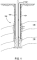
- FIG. 1 illustrates a schematic cross-sectional view of a wellbore 102, wherein a distributed acoustic sensing (DAS) system 110 may be used to perform acoustic sensing.
- a DAS system may be capable of producing the functional equivalent of 10's, 100's, or even 1000's of acoustic sensors. Properties of downhole formations surrounding or otherwise adjacent the wellbore 102 may be monitored over time based on the acoustic sensing. Further, hydrocarbon production may be controlled or reservoirs 108 may be managed based on the downhole formation properties sensed by in-well acoustic measurement methods using the DAS system 110.
- the wellbore 102 may have a casing 104 disposed within, through which production tubing 106 may be deployed.
- the DAS system 110 may comprise an acoustic energy source and a DAS device.
- the acoustic energy source may emit acoustic signals downhole.
- An optical waveguide, such as an optical fiber, within the wellbore 102 may function as the DAS device, measuring disturbances in scattered light that may be propagated within the waveguide (e.g., within the core of an optical fiber).
- the disturbances in the scattered light may be due to the acoustic signals, wherein the acoustic signals may change the index of refraction of the waveguide or mechanically deform the waveguide such that the Rayleigh scattered signal changes.
- Acoustic sensing based on DAS may use the Rayleigh backscatter property of the fiber's optical core and may spatially detect disturbances that are distributed along the fiber length. Such systems may rely on detecting phase changes brought about by changes in strain along the fiber's core. Externally generated acoustic disturbances may create very small strain changes to optical fibers. The acoustic disturbance may also be reduced or masked by a cable in which the fiber is deployed. In order to better detect changes in strain from acoustic disturbances, a fiber optic cable that has increased acoustic sensitivity is desired.
- GB 2 186 073 A discloses an arrangement for an optical fiber pressure sensor comprised of two coating layers concentrically clad to and coaxially oriented with an optical fiber.
- US 5,026,141 A1 discloses an optical fiber securely and continuously engaged by a structure, such as a pipeline, offshore platform, bridge, building, dam or even a natural object or fluid medium.
- Embodiments of the present invention provide a fiber optic cable used for performing Distributed Acoustic Sensing (DAS) with increased acoustic sensitivity.
- Acoustic sensing of a wellbore, pipeline, or other conduit/tube based on DAS may have increased acoustic sensitivity through fiber optic cable design, increasing the Rayleigh backscatter property of a fiber's optical core, and/or using inclusions or attachments to the cable or fiber.
- DAS Distributed Acoustic Sensing
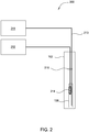
- FIG. 2 illustrates an embodiment of a DAS system 200, comprising an acoustic energy source 214 and a DAS device 213 both embedded within a cable 215 inside the wellbore 102, such as within the production tubing 106, as shown.
- a portion of the DAS system 200 may be permanently emplaced for sonic well logging.
- the acoustic energy source 214 may be controlled by an acoustic energy source controller 212, typically disposed at the surface.
- the controller 212 may transmit electrical pulses in an effort to stimulate piezoelectric elements in the acoustic energy source 214 to generate acoustic signals.
- the controller 212 may manage the pulse width and duty cycle of such electrical pulses.
- a DAS instrument 211 may introduce an optical pulse, using a pulsed laser, for example, into the DAS device 213.
- the DAS instrument 211 may also sense disturbances in the light propagating through the DAS device 213.
- the disturbances in the light may be due to the acoustic signals, wherein the acoustic signals may change the index of refraction of the DAS device 213 or mechanically deform the DAS device 213 such that the Rayleigh scattered signal changes.
- the acoustic signals may be generated passively (i.e., passive acoustic source), such as sounds produced from a valve or a turbulent flow within the wellbore 102 (e.g., gurgling or whistling), rather than from the active acoustic energy source 214.
- the passive acoustic signals may comprise seismic or micro-seismic activity in a formation surrounding a conduit.
- the DAS instrument 211 may send an optical signal into the DAS device 213 and may look at the naturally occurring reflections that are scattered back all along the DAS device 213 (i.e., Rayleigh backscatter), wherein the DAS device 213 may have increased acoustic sensitivity, as will be described in greater detail below.
- the wavelength of the optical signal sent by the DAS instrument 211 may be optimized for increased Rayleigh backscatter. Shorter wavelengths, which may reach a determined penetration depth, may produce greater Rayleigh backscatter within the DAS device 213, allowing for increased acoustic sensitivity. However, shorter wavelengths may limit the measurement range of the DAS device 213.
- the DAS instrument 211 may be able to measure the effect of the acoustic signal on the optical signal at all points along the waveguide, limited only by the spatial resolution.
- acoustic sensing based on DAS may be used in various other conduits besides the wellbore 102 (e.g., within a pipeline), but acoustic sensing performed within a wellbore will mainly be discussed hereinafter.
- the DAS device 213 may have increased acoustic sensitivity when compared to conventional optical fibers or fiber optic cables, wherein the acoustic energy that is transmitted from the surface of a fiber optic cable to fibers inside the cable may be increased by lowering the bulk modulus and/or increasing the acoustic coupling of the DAS device 213.
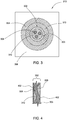
- FIG. 3 illustrates an embodiment of a cross-sectional view of a fiber optic cable suitable for use as the DAS device 213, where the suitable cable may comprise a fiber in metal tube (FIMT), somewhat similar to that described in United States Patent No. 7,024,081 to Dowd et al., issued April 4, 2006 .
- FIMT fiber in metal tube
- the DAS device 213 may comprise an FIMT 302 disposed in a protective outer tube (i.e., an armor layer) 304.
- the FIMT 302 may comprise an inner tube 303 surrounding one or more optical fibers 308, three of which are shown in the embodiment depicted in FIG. 3 .
- the optical fibers 308 may comprise a core, a cladding around the core, and a fiber coating surrounding the cladding.
- the inner tube 303 may comprise any of various suitable materials, such as metal.
- a filler material 310 may be disposed in the inner tube 303 and substantially fill ( e.g ., about 50%) the void spaces within the inner tube 303 surrounding the optical fibers 308 in an effort to support and prevent the optical fibers 308 from moving excessively within the inner tube 303, thereby reducing resonant frequencies.
- the filler material may comprise any of various suitable materials, such as one or more composites.
- the optical fibers 308 may be embedded into the filler material 310.
- FIG. 4 portrays only one optical fiber 308, one or more optical fibers 308 may have a serpentine orientation within the inner tube 303.
- Suitable filler materials 310 may comprise, but are not limited to, conventional thixotropic gels, grease compounds, and foams commonly used in the fiber optic cable industry for water blocking, filling and lubrication of optical fiber cables.
- the fill percentage of the filler material 310 may be increased to enhance acoustic coupling between the inner tube 303 and the optical fibers 308 (e.g., up to 100%, but there may be limitations due to thermal expansion of the filler material 310).
- the embodiment illustrated in FIG. 3 and described herein uses three optical fibers 308 in the inner tube 303, it is contemplated that one or more fibers 308 may be used.
- the FIMT 302 may be surrounded by the outer tube 304 and be configured to provide a gap 312 therebetween.
- a material similar to the filler material 310 may be used to fill the gap 312, thereby enhancing acoustic coupling between the FIMT 302 and the outer tube 304.
- the DAS device 213 may comprise an encapsulant material to enhance acoustic coupling between the outer tube 304 and an environment surrounding the outer tube 304.
- a polymer/composite tubing may be disposed over the inner tube 303 to further enhance acoustic coupling, wherein an increased acoustic energy may be transferred to the at least one optical fiber 308.
- the inner tube 303 may also be replaced with the polymer/composite tubing.
- a polymer/composite jacket 306 may be disposed over the outer tube 304, wherein the jacket 306 may have various shapes and sizes in an effort to increase coupling to the production tubing 106 or formation (e.g., square, round, parabolic, or elliptical).
- the material for the polymer/composite tubing or jacket 306 may be selected for increased acoustic coupling.
- the desired polymer/composite may most likely have high elasticity and a low bulk modulus.
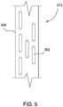
- FIG. 5 illustrates an embodiment of a partial side view of the optic cable of FIG. 3 suitable for use as a DAS device 213.
- the outer tube 304 may comprise one or more slotted holes 502 to allow fluid ingress.
- the slotted holes 502 may allow fluid to collect in the gaps 312, thereby enhancing acoustic coupling between the FIMT 302 and the outer tube 304. Since fluids may have different compositions, the fluids allowed through the slotted holes 502 may provide different levels of acoustic sensitivity along the DAS device 213, which may be problematic.
- the slotted holes 502 may allow salt water in, which may corrode the inner tube 303 of the FIMT 302, so corrosion-resistant material may be used for the inner tube 303.
- the optical fiber may have increased acoustic sensitivity by changing the bulk modulus of the optical fiber itself. This may be accomplished by introducing holes lengthwise within the cladding of the fiber.
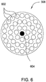
- FIG. 6 illustrates an embodiment of a cross-sectional view of a microstructured optical fiber suitable for use as optical fibers 308. The air, other gas, or liquids within holes 602 may reduce the modulus of the fiber structure so that the fiber core 604 may be more affected by external pressures, such as that created by an acoustic wave.
- the size, number, and location of the holes 602 along the fiber 308 may be designed as to not affect the waveguide properties of the fiber 308, but may enhance the strain sensitivity (e.g., arranging the holes 602 such that the pressures created by the acoustic wave remain focused on the fiber core 604).
- Optical fibers made with holes may be known as “holey fibers” or “microstructured fibers.”
- holes and other microstructures may be embedded into the fiber 308 during a drawing process, which may improve the distributed acoustic sensing capability of the DAS device 213.
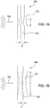
- FIG. 7A illustrates an embodiment of a partial side view of a typical fiber 308 that may be disposed within a fiber optic cable suitable for use as a DAS device 213.
- the optical fiber 308 may comprise a fiber coating 701 and a cladding 702 surrounding a core 800 (shown in FIG. 8 ), wherein the cladding 702 has a diameter D (e.g., a standard optical fiber cladding diameter of 125 ⁇ m).
- Downhole acoustic signals 704 may hit the DAS device 213, wherein the signals 704 may propagate to the inside of the DAS device 213 and thereby change the index of refraction of the cladding 702 (and that of the core 800) or mechanically deform the optical fiber a length l by compressing the coating 701, and hence the cladding 702, with the acoustic signal 704 ( i.e., creating a local Poisson-effect reaction).
- FIG. 7B illustrates an embodiment of a partial side view of a fiber 308 that may be disposed within a fiber optic cable suitable for use as a DAS device 213, wherein the cladding 702' has a smaller diameter d ( e.g., a diameter of about 80 ⁇ m).
- Downhole acoustic signals 704 may hit the DAS device 213, wherein the signals 704 may propagate to the inside of the cable and thereby change the index of refraction of the cladding 702' (and that of the core 800) or mechanically deform the waveguide a length L, where L > l.
- the signals 704 may mechanically deform the optical fiber by stretching a local section of the fiber, such that the fiber may be lengthened. Fibers having a smaller diameter may be deformed or stretched a greater length because it may take substantially less energy to deform the fibers.
- the DAS device 213 may be designed for increased acoustic sensitivity by changing (e.g., lowering) the modulus of the fiber coating 701.
- the thickness of the fiber coating 701 may be changed (e.g., by increasing the thickness).
- the fiber coating 701 may have graded layers with different materials and/or thicknesses. Since the fiber coating 701 may be coupled directly to the optical fiber 702', the fiber coating 701 may pull/strain the cladding 702' when acoustic signals 704 hit the DAS device 213 and propagate to the inside of the DAS device 213.
- FIG. 8 illustrates an embodiment of a cross-sectional view of a fiber 308 that may be disposed within a fiber optic cable suitable for use as a DAS device 213, comprising the core 800, a cladding 702' surrounding the core, and graded layers 802, 804 of the fiber coating.
- the graded layers 802, 804 may comprise different materials and have different thicknesses ( e.g ., t 2 > t 1 ). Although only two graded layers 802, 804 are depicted in FIG. 8 , the fiber 308 may comprise one, two, or more fiber coating layers.
- the DAS device 213 may have increased acoustic sensitivity by using different core materials or index profiles to enhance the Rayleigh backscatter of the at least one fiber within the DAS device 213 (i.e., modifying the fiber composition).
- one or more sections of the fiber may have increased acoustic sensitivity to provide localized Rayleigh backscatter.
- the fiber or sections of the fiber may be highly doped with germanium (Ge) to increase Rayleigh scattering ( i.e., modify dopants to increase Rayleigh scattering).
- the fiber may be a higher numerical aperture fiber.
- the DAS device 213 may comprise a plastic optical fiber, which may have a lower bulk modulus than traditional glass fibers, wherein the lower bulk modulus may yield increased acoustic sensitivity.
- the DAS instrument 211 may be sensitive to the phase changes in the randomly distributed Rayleigh scatter profile of fibers that may be disposed within a fiber optic cable suitable for use as a DAS device 213.
- the sensitivity of the DAS measurement may be enhanced by using a fiber with a modulated Rayleigh scatter profile to increase the sensitivity to phase changes.
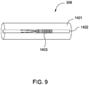
- FIG. 9 illustrates an embodiment of a partial side view of an optical fiber 308 that may be disposed within a fiber optic cable suitable for use as a DAS device 213, the optical fiber 308 comprising a cladding 1401 and a core 1402, wherein the core 1402 may comprise a modulated Rayleigh scatter cross-section 1403.
- Typical factors that affect the Rayleigh scatter profile are doping type, concentration and profile, mode diameter, and mode profile.
- Such modulation may be created during the production of the fiber 308, for example, by modulating the draw parameters or by a modulated preform. Such modulation may also be induced by processing the fiber 308, for example by thermal, chemical, photochemical, or mechanical means. For some embodiments, the modulation may be written into a long-period fiber grating (LPFG) to create unique acoustic signatures along the length of the DAS device 213.
- LPFG long-period fiber grating
- the DAS device 213 may comprise one or more localized sensing regions along the length of the device 213, wherein the localized sensing regions may have increased acoustic sensitivity as mentioned above in previous embodiments.
- the localized sensing regions may be placed in areas of the conduit/tube where acoustic measurements may be desired.
- the remaining portions of the DAS device 213 may comprise a standard fiber functioning as a transmission line.
- FIG. 10 illustrates a DAS device 213 comprising the one or more localized sensing regions 902 and other segments 904 of the DAS device 213 functioning as a transmission line.
- the localized sensing regions may comprise a combination of the embodiments described above.
- one localized sensing region may include a DAS device with the FIMT with slotted holes in the armor layer ( FIG. 5 ), and another localized sensing region may have a DAS device with a smaller diameter fiber of about 80 ⁇ m ( FIG. 7B ).
- one sensing region 902 may have a first modulation (or an LPFG with a first modulation), while a second sensing region 902 may have a second modulation (or an LPFG with a second modulation) different from the first modulation, wherein the different modulations may allow one to distinguish the sensing regions 902.
- FIG. 11 illustrates an embodiment of a DAS system 1000 using a wireline-conveyed acoustic energy source 214 and a DAS device 213 wrapped in a spiral manner outside the casing 104 of the wellbore 102 for at least one length 1002 1 along the casing 104 to perform in-depth acoustic sensing. Wrapping the DAS device 213 for the at least one length 1002 1 may allow more dense measurements to be made along the at least one length 1002 1 , due to the increased number of functionally equivalent acoustic sensors, thereby increasing sensitivity in this region.
- the at least one length 1002 1 along the casing 104 to perform in-depth acoustic sensing may comprise the localized sensing region 902.
- the DAS device 213 may run outside along the length of the casing 104 as in previous embodiments. There may be up to n areas wherein in-depth and more typical acoustic sensing may be performed (1002 n and 1004 n ).
- the other areas 1004 1 along the casing 104 may comprise the other segments 904 of the DAS device 213 (e.g., standard glass optical fiber).
- FIG. 12 illustrates an embodiment of a DAS system 1100 using a DAS device 213 circularly wrapped around the tubing 106 of the wellbore 102 for at least one discrete circumference 1102 1 along the tubing 106 to perform in-depth acoustic sensing.
- the acoustic signals may be generated passively, such as sounds produced from a valve or a turbulent flow within the wellbore 102 (e.g., gurgling or whistling), rather than from the active acoustic energy source 214.
- the discrete circumference 1102 1 may comprise one or more wrappings of the DAS device 213, wherein the wrappings may overlap one another.
- the at least one circumference 1102 1 along the tubing 106 to perform in-depth acoustic sensing may comprise the localized sensing region 902.
- the DAS device 213 may run outside along the length of the tubing 106 as in previous embodiments. There may be up to n areas wherein both in-depth and more typical acoustic sensing may be performed (1102 n and 1004 n ). Some embodiments may have a combination of spiral and circular wrapping at different areas around the casing 104 or the tubing 106. For some embodiments, the other areas 1004 1 along the casing 104 may comprise the other segments 904 of the DAS device 213 (e.g., standard glass optical fiber).
- local attachments may be added to the DAS device 213 to provide increased acoustic sensitivity.
- mechanical amplifiers e.g., resonant sensor mechanisms
- resonant sensor mechanisms comprise tuned mechanical amplifiers such as Helmholtz cavity structures, tuning fork structures, or flextensional structures.
- the local attachments may be added at particular locations, such as noted in FIG. 10 (e.g., sensing regions 902), in order to create the quasi-distributed array of sensitizing components.
- the resonant sensor mechanisms may be arranged with any of the DAS devices described herein, any conventional DAS device, or any future developed DAS device.
- portions of the DAS device 213 may be clamped to the tubing 106 by clamps, creating physical contact between the DAS device 213 and the tubing 106. Therefore, the portions of the DAS device 213 that are clamped to the tubing 106 may have increased acoustic sensitivity.
- the acoustic energy source 214 may be operated in a tone burst mode that may be decoded by the DAS instrument 211 (i.e., excitation frequency).
- the tone burst mode of the source 214 may provide a format for accomplishing two purposes: (1) creating a tone that matches the resonant frequency of the sensitizing components and (2) providing the normal pulsing sequence that is necessary for time-of-flight based location measurements.
- the acoustic source may be passive, as long as the acoustic source produces the resonant frequencies of the sensitizing components.
- the tone burst mode may encode many different frequencies, thereby selectively exciting and interrogating variously spaced resonant sensitizing components.
- the resonant sensor mechanisms may be interrogated using the acoustic energy source in a tone burst mode so as to enable signal processors to conduct non-crosstalking measurements of individual resonant sensor mechanisms.
- variously spaced valves may be designed to generate an acoustic signal at different frequencies.
- the resonant sensing mechanisms may have one or more types of configurations.
- the resonant sensing mechanisms may be attachments to the DAS device 213.
- the mechanisms may be attached to an outer tube or an inner tube of the DAS device 213.
- the mechanisms may be attached to one or more fibers within the inner tube.
- the resonant sensing mechanisms may be added serially inline with the DAS device 213.
- FIG. 13A illustrates an embodiment of a DAS system, wherein one or more resonant sensing mechanisms 1202 may be attachments to the DAS device 213.
- the mechanism 1202 may provide for the retention of the exterior of the DAS device 213, and then pass the internal fibers 308 of the DAS device 213 through the mechanism 1202.
- the attached mechanism 1202 may resonate at the frequency of the source tone (i.e., excitation frequency) and may exhibit a high quality factor (Q). Therefore, the mechanism 1202 may enhance the configuration sensitivity by amplifying the acoustic pressure field on the fibers 308.
- the amplified acoustic pressure field may provide for enhanced acoustic signals detected by the DAS instrument 211.
- FIG. 13B illustrates an embodiment of a DAS system, wherein one or more resonant sensing mechanisms 1204 may be attachments to the DAS device 213.
- the mechanism 1204 may provide for the retention of the exterior of the DAS device 213, and then the fibers 308 may be wrapped around the perimeter of the mechanism 1204.
- the fibers 308 may be attached to the inside perimeter of the mechanism 1204.
- the attached mechanism 1204 may resonate at the frequency of the source tone (i.e., excitation frequency) and may exhibit a high Q. Therefore, the mechanism 1204 may enhance the configuration sensitivity by imposing an amplified strain signal on the fibers 308.
- the strain may provide for enhanced acoustic signals detected by the DAS instrument 211.
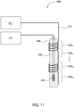
- FIG. 13C illustrates an embodiment of a DAS system, wherein the DAS device 213 is opened so that at least one fiber 308 is spliced on to an input pigtail 1208 in order to pass the optical signal through a resonant sensor 1206.
- the optical signal may exit an output pigtail 1209 through a similar splice, completing the continuity of the cable system.
- the resonant sensor 1206 may contain a fused, monolithic glass assembly providing for an internal cane waveguide 1210 (e.g., a waveguide having a diameter of at least 0.3 mm) and an external shell 1212.
- the fused assembly may be fabricated such that it resonates with a high Q at the tone of the source 214, thereby amplifying the effect of the incoming acoustic fields on the internal cane waveguide 1210.
- Owing to the amplification effect of the high Q there may be an enhanced acoustic field imposed on the cane waveguide 1210 as well as an enhanced strain imposed on the cane waveguide 1210.
- the enhanced acoustic field and strains may provide for increased sensitivity to signals detected by the DAS instrument 211.
- the diameter of the external shell 1212 may be greater in the area surrounding the cane waveguide 1210 than at the ends of the external shell 1212. Therefore, when pressures from the incoming acoustic fields hit the external shell 1212, the cane waveguide 1210 may be placed under greater compression, amplifying the effect of the incoming acoustic fields even further.
- FIG. 14 illustrates operations 1400 for performing acoustic sensing based on DAS with increased acoustic sensitivity.
- the operations may begin by providing an acoustic energy source, such as active acoustic energy source 214, wherein the acoustic energy source produces acoustic stimulation along a length of a conduit.
- the acoustic signals may be generated passively, such as sounds produced from a valve or a turbulent flow within the wellbore 102 ( e.g., gurgling or whistling), rather than from the active acoustic energy source 214.
- a fiber optic cable such as the DAS device 213, may be provided along the length of the conduit, wherein the fiber optic cable has increased acoustic sensitivity.
- DAS may be performed along the length of the conduit by receiving the acoustic signals using the fiber optic cable.
- a DAS instrument such as DAS instrument 211, may measure disturbances in scattered light that may be propagated within the DAS device. The disturbances in the scattered light may be due to the acoustic signals (e.g., generated by the acoustic energy source), wherein the acoustic signals may change the index of refraction or mechanically deform the DAS device such that the Rayleigh scattered signal changes.
- Increasing the acoustic sensitivity of a DAS device used in a DAS system may allow better detection of changes in strain along a fiber's core from acoustic disturbances.
- increasing the acoustic sensitivity may allow for detection of issues with components, such as a valve, choke, or sleeve (e.g., whether a valve is open or closed).
- a unique acoustic signature may be determined for each component and/or situation (e.g., leak detection) so as to isolate issues, wherein a signature may be compared to a catalog or database of acoustic signatures (e.g., a lookup table).
- increasing the acoustic sensitivity may allow for measurement of any downhole vibration as a quality control or health check of completion components.
- increasing the acoustic sensitivity may allow for measurement of vibrations that may be used as a seismic source.
- increasing the acoustic sensitivity may allow for correlation of vibration/acoustics to various downhole conditions associated with, for example, chokes at various valve positions, gas lift valve operations, downhole pumps for artificial lift, downhole separators, subsurface safety valve (SSSV) operations, inflow of fluids from a reservoir, inflow through sand screens, inflow control devices (ICDs), gravel packing operations, downhole perforating, downhole stimulation, leak detection, and seismic and micro-seismic disturbances.
- SSSV subsurface safety valve
- ICDs inflow control devices
- gravel packing operations downhole perforating, downhole stimulation, leak detection, and seismic and micro-seismic disturbances.
- a unique acoustic signature may be predetermined to indicate when the gas lift valve is operating at the opening/closing pressure.
- a unique acoustic signature may be predetermined to indicate when a load is transferred from one valve of the pump to another valve.
- a unique acoustic signature may be predetermined to indicate whether a particular phase has been separated from a fluid stream.
- a unique acoustic signature may be predetermined to indicate a certain production rate from the reservoir.
- a unique acoustic signature may be predetermined to indicate whether the gravel packing operation was successful (e.g., no production of formation sand).
- different acoustic signatures may be predetermined to indicate how well a conduit has been perforated.
- flow metering measurements such as flow velocity and speed of sound in a fluid may be determined.
- coarse flow measurements may be determined by detecting propagating disturbances.
- the percentage of sand in a flow may be determined based on an acoustic signature.
- the integrity of a tubing may be determined by detecting changes in an acoustic signature, which may indicate a leak or corrosion of the tubing. Corrosion may cause thinning of the tube, which may yield a different acoustic signature than an uncorroded tube. A leak of the tubing may also yield a different acoustic signature, such as a gurgling or whistling noise.
- tracking the location of a pig along a pipeline or detecting a slug in a wellbore may be determined based on an acoustic signature.
Claims (10)
- Câble de fibre optique (213) utilisé pour une détection acoustique répartie (DAS), comprenant :une ou plusieurs régions de DAS (902) le long d'une longueur du câble ; etun ou plusieurs segments (904) comprenant une fibre optique standard, fonctionnant comme une ligne de transmission et connectant les une ou plusieurs régions de DAS (902), dans lequel les régions de DAS (902) ont une sensibilité acoustique supérieure aux un ou plusieurs segments (904), et dans lequel les régions de DAS (902) ont un diamètre nominal de gaine de fibre optique d'environ 80 µm et les un ou plusieurs segments (904) ont un diamètre nominal de gaine de fibre optique de 125 µm.
- Câble de fibre optique (213) selon la revendication 1, dans lequel les une ou plusieurs régions de DAS (902) ont différentes modulations pour distinguer au moins une première région de DAS (902) d'une seconde région de DAS (902).
- Câble de fibre optique (213) selon les revendications 1 ou 2, comprenant en outre des fixations locales pour fournir une sensibilité acoustique accrue, dans lequel les fixations locales comprennent un mécanisme de capteur résonant pour améliorer le couplage des signaux acoustiques et dans lequel le mécanisme de capteur résonant est fixé à un tube extérieur ou un tube intérieur du câble.
- Câble de fibre optique (213) selon les revendications 1 ou 2, comprenant en outre des fixations locales pour fournir une sensibilité acoustique accrue, dans lequel les fixations locales comprennent un mécanisme de capteur résonant (1206) pour améliorer le couplage des signaux acoustiques et dans lequel le mécanisme de capteur résonant (1206) est fixé à une ou plusieurs fibres au sein d'un tube intérieur du câble (213).
- Câble de fibre optique (213) selon la revendication 4, dans lequel le mécanisme de capteur résonant (1206) est épissé en un trajet de signal d'au moins l'une des une ou plusieurs fibres en utilisant des amorces d'entrée et de sortie (1208, 1209) sur des composants de guide d'onde (1210) contenus au sein du mécanisme de capteur résonant (1206).
- Câble de fibre optique (213) selon la revendication 5, dans lequel le mécanisme de capteur résonant contient un guide d'onde tige épissé en un trajet de fibre en utilisant les amorces d'entrée et de sortie (1208, 1209).
- Câble de fibre optique (213) selon les revendications 5 ou 6, comprenant en outre un guide d'onde de fibre (1210) couplé au mécanisme de capteur résonant (1206), dans lequel le guide d'onde de fibre (1210) est épissé dans un trajet de fibre en utilisant les amorces d'entrée et de sortie (1208, 1209).
- Câble de fibre optique (213) selon l'une quelconque des revendications 3 à 7, dans lequel le mécanisme de capteur résonant (1206) comprend des amplificateurs mécaniques accordés tels que des structures de cavité Helmholtz, des structures de diapason, ou des structures flextensionnelles.
- Câble de fibre optique (213) selon l'une quelconque des revendications 3 à 8, dans lequel les fixations locales sont configurées pour l'interrogation en utilisant une source d'énergie acoustique dans un mode d'impulsions sonores pour permettre à des processeurs de signaux de conduire des mesures sans diaphonie de fixations locales individuelles.
- Câble de fibre optique (213) selon l'une quelconque des revendications 1 à 9, dans lequel au moins l'une des une ou plusieurs régions de DAS (902) sont configurées pour être attachées le long d'une longueur d'un conduit, pour coupler des pressions, créées par des ondes acoustiques générées le long de la longueur du conduit (106), au câble (213).
Applications Claiming Priority (2)
| Application Number | Priority Date | Filing Date | Title |
|---|---|---|---|
| US35592410P | 2010-06-17 | 2010-06-17 | |
| EP11250594.6A EP2418466B1 (fr) | 2010-06-17 | 2011-06-17 | Système et méthode de détection acoustique répartie utilisant des fibres optiques perforées |
Related Parent Applications (2)
| Application Number | Title | Priority Date | Filing Date |
|---|---|---|---|
| EP11250594.6A Division EP2418466B1 (fr) | 2010-06-17 | 2011-06-17 | Système et méthode de détection acoustique répartie utilisant des fibres optiques perforées |
| EP11250594.6A Division-Into EP2418466B1 (fr) | 2010-06-17 | 2011-06-17 | Système et méthode de détection acoustique répartie utilisant des fibres optiques perforées |
Publications (2)
| Publication Number | Publication Date |
|---|---|
| EP3321648A1 EP3321648A1 (fr) | 2018-05-16 |
| EP3321648B1 true EP3321648B1 (fr) | 2021-04-21 |
Family
ID=44561340
Family Applications (2)
| Application Number | Title | Priority Date | Filing Date |
|---|---|---|---|
| EP17207250.6A Active EP3321648B1 (fr) | 2010-06-17 | 2011-06-17 | Câble de fibre optique pour détection acoustique distribuée doté d'une sensibilité acoustique accrue |
| EP11250594.6A Active EP2418466B1 (fr) | 2010-06-17 | 2011-06-17 | Système et méthode de détection acoustique répartie utilisant des fibres optiques perforées |
Family Applications After (1)
| Application Number | Title | Priority Date | Filing Date |
|---|---|---|---|
| EP11250594.6A Active EP2418466B1 (fr) | 2010-06-17 | 2011-06-17 | Système et méthode de détection acoustique répartie utilisant des fibres optiques perforées |
Country Status (4)
| Country | Link |
|---|---|
| US (2) | US9255836B2 (fr) |
| EP (2) | EP3321648B1 (fr) |
| CA (3) | CA2858016C (fr) |
| NO (1) | NO2418466T3 (fr) |
Cited By (1)
| Publication number | Priority date | Publication date | Assignee | Title |
|---|---|---|---|---|
| WO2023009966A1 (fr) * | 2021-07-28 | 2023-02-02 | Baker Hughes Oilfield Operations Llc | Fibre à rétrodiffusion renforcée avec amélioration de la conicité |
Families Citing this family (104)
| Publication number | Priority date | Publication date | Assignee | Title |
|---|---|---|---|---|
| US8584519B2 (en) * | 2010-07-19 | 2013-11-19 | Halliburton Energy Services, Inc. | Communication through an enclosure of a line |
| WO2012054635A2 (fr) * | 2010-10-19 | 2012-04-26 | Weatherford/Lamb, Inc. | Surveillance à l'aide de technologie de détection acoustique répartie (das) |
| US8902078B2 (en) | 2010-12-08 | 2014-12-02 | Halliburton Energy Services, Inc. | Systems and methods for well monitoring |
| GB201100636D0 (en) * | 2011-01-14 | 2011-03-02 | Qinetiq Ltd | Fibre optic distributed sensing |
| GB201103254D0 (en) * | 2011-02-25 | 2011-04-13 | Qinetiq Ltd | Distributed acoustic sensing |
| GB201114834D0 (en) * | 2011-08-26 | 2011-10-12 | Qinetiq Ltd | Determining perforation orientation |
| JP5948035B2 (ja) * | 2011-10-05 | 2016-07-06 | ニューブレクス株式会社 | 分布型光ファイバ音波検出装置 |
| US10173286B2 (en) | 2011-10-19 | 2019-01-08 | Weatherford Technology Holdings, Llc | Optical fiber coating to reduce friction and static charge |
| BR112014014565B1 (pt) * | 2011-12-15 | 2022-06-28 | Shell Internationale Research Maatschappij B.V. | Sistema de detecção acústica de fibra óptica distribuída |
| GB201203854D0 (en) * | 2012-03-05 | 2012-04-18 | Qinetiq Ltd | Monitoring flow conditions downwell |
| WO2014014378A1 (fr) * | 2012-07-19 | 2014-01-23 | Siemens Aktiengesellschaft | Système permettant de surveiller une installation technique |
| GB2519009B (en) | 2012-08-01 | 2017-09-13 | Shell Int Research | Cable comprising twisted sinusoid for use in distributed sensing |
| EP2725186B1 (fr) * | 2012-10-25 | 2019-08-07 | GE Oil & Gas UK Limited | Gaine pour corps de tuyau flexible et son procédé de production |
| US10247840B2 (en) * | 2013-01-24 | 2019-04-02 | Halliburton Energy Services, Inc. | Optical well logging |
| US20140202240A1 (en) * | 2013-01-24 | 2014-07-24 | Halliburton Energy Services, Inc. | Flow velocity and acoustic velocity measurement with distributed acoustic sensing |
| US9581489B2 (en) | 2013-01-26 | 2017-02-28 | Halliburton Energy Services, Inc. | Distributed acoustic sensing with multimode fiber |
| US9279317B2 (en) * | 2013-03-14 | 2016-03-08 | Baker Hughes Incorporated | Passive acoustic resonator for fiber optic cable tubing |
| GB201312549D0 (en) * | 2013-07-12 | 2013-08-28 | Fotech Solutions Ltd | Monitoring of hydraulic fracturing operations |
| US9447679B2 (en) | 2013-07-19 | 2016-09-20 | Saudi Arabian Oil Company | Inflow control valve and device producing distinct acoustic signal |
| US9321222B2 (en) * | 2013-08-13 | 2016-04-26 | Baker Hughes Incorporated | Optical fiber sensing with enhanced backscattering |
| US10386215B2 (en) | 2013-08-23 | 2019-08-20 | Baker Hughes, A Ge Company, Llc | Method for monitoring a flow using distributed acoustic sensing |
| GB2518359B (en) * | 2013-09-13 | 2018-05-23 | Silixa Ltd | Acoustic cables |
| EP3044554B1 (fr) | 2013-09-13 | 2023-04-19 | Silixa Ltd. | Câble à fibre optique pour un système de détection acoustique distribué |
| US9739142B2 (en) | 2013-09-16 | 2017-08-22 | Baker Hughes Incorporated | Fiber optic vibration monitoring |
| US20150082891A1 (en) * | 2013-09-24 | 2015-03-26 | Baker Hughes Incorporated | System and method for measuring the vibration of a structure |
| WO2015085423A1 (fr) | 2013-12-13 | 2015-06-18 | Hifi Engineering Inc. | Appareil pour détecter des signaux acoustiques dans un logement |
| EP3099893A4 (fr) * | 2014-01-31 | 2017-10-18 | Services Pétroliers Schlumberger | Surveillance d'équipement associé à un trou de forage/conduit |
| US10343193B2 (en) | 2014-02-24 | 2019-07-09 | The Boeing Company | System and method for surface cleaning |
| EP3126808A1 (fr) | 2014-04-04 | 2017-02-08 | Exxonmobil Upstream Research Company | Surveillance en temps réel d'une surface métallique |
| WO2015183441A1 (fr) * | 2014-05-27 | 2015-12-03 | Baker Hughes Incorporated | Procédé d'étalonnage pour détection acoustique distribuée à fibre optique de fond de trou |
| GB2540720B (en) * | 2014-07-31 | 2019-03-13 | Halliburton Energy Services Inc | A system comprising a composite downhole slickline cable and method of use thereof |
| US10365136B2 (en) * | 2014-08-20 | 2019-07-30 | Halliburton Energy Services, Inc. | Opto-acoustic flowmeter for use in subterranean wells |
| CA2954736C (fr) * | 2014-08-20 | 2020-01-14 | Halliburton Energy Services, Inc. | Detection d'ecoulement dans des puits souterrains |
| US10120094B2 (en) * | 2014-08-25 | 2018-11-06 | Halliburton Energy Services, Inc. | Seismic monitoring below source tool |
| WO2016057047A1 (fr) * | 2014-10-10 | 2016-04-14 | Halliburton Energy Services, Inc. | Procédé de fabrication d'un système de détection acoustique améliorée |
| BR112017013331A2 (pt) | 2015-01-13 | 2018-04-10 | Halliburton Energy Services Inc | método, sistema e meio legível por máquina |
| CA2972616C (fr) | 2015-01-19 | 2022-11-29 | Domino Taverner | Transducteurs et emetteurs acoustiques pour la detection acoustique basee sur fibre optique |
| US10843290B2 (en) | 2015-01-19 | 2020-11-24 | Weatherford Technology Holdings, Llc | Acoustically enhanced optical cables |
| CA2978701A1 (fr) * | 2015-03-09 | 2016-09-15 | Baker Hughes, A Ge Company, Llc | Surveillance de contraintes distribuee pour outils de fond de trou |
| WO2016144336A1 (fr) * | 2015-03-10 | 2016-09-15 | Halliburton Energy Services Inc. | Système de surveillance de puits de forage mettant en œuvre un boîtier de câble à fibre optique sensible aux contraintes |
| WO2016144334A1 (fr) * | 2015-03-10 | 2016-09-15 | Halliburton Energy Services Inc. | Boîtier de câble à fibre optique sensible aux contraintes pour détection acoustique répartie de fond de trou |
| WO2016144337A1 (fr) | 2015-03-10 | 2016-09-15 | Halliburton Energy Services Inc. | Procédé de fabrication d'un câble de détection acoustique répartie |
| US9448312B1 (en) | 2015-03-11 | 2016-09-20 | Baker Hughes Incorporated | Downhole fiber optic sensors with downhole optical interrogator |
| US9926780B2 (en) * | 2015-07-30 | 2018-03-27 | Halliburton Energy Services, Inc. | Micro-structured fiber optic cable for downhole sensing |
| MX2017016618A (es) | 2015-07-31 | 2018-05-15 | Halliburton Energy Services Inc | Dispositivo acustico para reducir los ruidos sismicos inducidos por ondas de cable. |
| US10133017B2 (en) * | 2015-08-07 | 2018-11-20 | Pgs Geophysical As | Vented optical tube |
| US9719846B2 (en) | 2015-08-14 | 2017-08-01 | Halliburton Energy Services, Inc. | Mud pulse detection using distributed acoustic sensing |
| WO2017074374A1 (fr) * | 2015-10-29 | 2017-05-04 | Halliburton Energy Services, Inc. | Détection de course de pompe à boue à l'aide de détection acoustique distribuée |
| US10202845B2 (en) * | 2015-12-14 | 2019-02-12 | Baker Hughes, A Ge Company, Llc | Communication using distributed acoustic sensing systems |
| US20190056523A1 (en) * | 2015-12-16 | 2019-02-21 | Halliburton Energy Services, Inc. | Electro acoustic technology seismic detection system with down-hole source |
| US10711599B2 (en) * | 2015-12-16 | 2020-07-14 | Halliburton Energy Services, Inc. | Electroacoustic pump-down sensor |
| WO2017116965A1 (fr) * | 2015-12-28 | 2017-07-06 | Shell Oil Company | Utilisation de support de fibre pour fournir une fibre optique dans un puits de forage |
| EP3670830B1 (fr) | 2016-04-07 | 2021-08-11 | BP Exploration Operating Company Limited | Détection d'événements de fond de trou à l'aide de caractéristiques de domaine de fréquence acoustique |
| US11530606B2 (en) | 2016-04-07 | 2022-12-20 | Bp Exploration Operating Company Limited | Detecting downhole sand ingress locations |
| WO2017212559A1 (fr) * | 2016-06-08 | 2017-12-14 | ニューブレクス株式会社 | Câble pour mesurer la pression, la température et la répartition des contraintes d'un matériau |
| US10451497B2 (en) * | 2017-08-11 | 2019-10-22 | Ut-Battelle, Llc | Stress sensor for cement or fluid applications |
| US10739169B2 (en) | 2017-03-23 | 2020-08-11 | Ofs Fitel, Llc | Flat profile optical fiber cable for distributed sensing applications |
| EP3583296B1 (fr) | 2017-03-31 | 2021-07-21 | BP Exploration Operating Company Limited | Surveillance de puits et de surcharge à l'aide de capteurs acoustiques distribués |
| BR112019022068A2 (pt) * | 2017-05-12 | 2020-05-05 | Baker Hughes A Ge Co Llc | interrogação acústica de múltiplas frequências para orientação azimutal de ferramentas de fundo de poço |
| CA3064899A1 (fr) * | 2017-05-31 | 2018-12-06 | Corning Research & Development Corporation | Cable optique a detection de contrainte avec couches adaptees a l'impedance acoustique |
| AU2018321150A1 (en) | 2017-08-23 | 2020-03-12 | Bp Exploration Operating Company Limited | Detecting downhole sand ingress locations |
| EP3695099A2 (fr) | 2017-10-11 | 2020-08-19 | BP Exploration Operating Company Limited | Détection d'événements à l'aide de caractéristiques acoustiques de domaine fréquentiel |
| US10330526B1 (en) * | 2017-12-06 | 2019-06-25 | Saudi Arabian Oil Company | Determining structural tomographic properties of a geologic formation |
| EP3721211A4 (fr) * | 2017-12-06 | 2021-08-18 | California Institute of Technology | Système d'analyse d'un échantillon d'essai et procédé associé |
| US10338336B1 (en) | 2018-01-08 | 2019-07-02 | Weatherford Technology Holdings, Llc | Fiber optic cable for inhibiting breaching fluid flow |
| US10365537B1 (en) * | 2018-01-08 | 2019-07-30 | Saudi Arabian Oil Company | Directional sensitive fiber optic cable wellbore system |
| US10247838B1 (en) * | 2018-01-08 | 2019-04-02 | Saudi Arabian Oil Company | Directional sensitive fiber optic cable wellbore system |
| AT520557B1 (de) * | 2018-01-24 | 2019-05-15 | Anton Paar Gmbh | Verfahren zur Ermittlung eines korrigierten Werts für die viskositätsabhängige Schallgeschwindigkeit in einem zu untersuchenden Fluid |
| GB2571540B (en) | 2018-02-28 | 2020-10-28 | Craley Group Ltd | Improvements in or relating to the monitoring of fluid pipes |
| WO2019209270A1 (fr) * | 2018-04-24 | 2019-10-31 | Halliburton Energy Services, Inc. | Profilage de profondeur et de distance avec câbles à fibres optiques et coup de belier |
| US20210277771A1 (en) * | 2018-05-04 | 2021-09-09 | Halliburton Energy Services, Inc. | Distributed acoustic sensing for coiled tubing characteristics |
| US11209558B2 (en) * | 2018-05-09 | 2021-12-28 | Conocophillips Company | Measurement of poroelastic pressure response |
| US11598928B2 (en) | 2018-07-20 | 2023-03-07 | Weatherford Technology Holdings, Llc | Cable to reduce optical fiber movement and methods to fabricate |
| CN108645501A (zh) * | 2018-08-09 | 2018-10-12 | 平湖波汇通信科技有限公司 | 一种基于分布式光纤传感水管运行监测系统 |
| US10927645B2 (en) | 2018-08-20 | 2021-02-23 | Baker Hughes, A Ge Company, Llc | Heater cable with injectable fiber optics |
| US20210389486A1 (en) | 2018-11-29 | 2021-12-16 | Bp Exploration Operating Company Limited | DAS Data Processing to Identify Fluid Inflow Locations and Fluid Type |
| GB201820331D0 (en) | 2018-12-13 | 2019-01-30 | Bp Exploration Operating Co Ltd | Distributed acoustic sensing autocalibration |
| CN109596206B (zh) * | 2019-01-25 | 2021-01-15 | 武汉理工大学 | 基于液体填充光子晶体光纤的振动传感器 |
| EA202192444A1 (ru) * | 2019-03-14 | 2022-02-24 | Бп Эксплорейшн Оперейтинг Компани Лимитед | Обнаружение событий в поточной линии с использованием акустических признаков в частотной области |
| EP3985364A4 (fr) | 2019-06-12 | 2022-07-13 | NEC Corporation | Câble à fibre optique pour détection d'onde sonore |
| CN112240195B (zh) * | 2019-07-16 | 2024-01-30 | 中国石油大学(华东) | 基于分布式光纤声音监测的油气井出砂监测模拟实验装置及工作方法 |
| CN112240196B (zh) * | 2019-07-16 | 2023-08-18 | 中国石油大学(华东) | 一种基于分布式光纤声音、温度监测的井筒生产剖面监测模拟实验装置及方法 |
| CN110344816B (zh) * | 2019-07-16 | 2023-05-09 | 中国石油大学(华东) | 一种基于分布式光纤声音监测的油气井出砂监测方法 |
| CN110703349B (zh) * | 2019-10-12 | 2021-10-08 | 海隆石油工业集团有限公司 | 一种基于光纤传感的清管器卡堵定位装置和方法 |
| CA3154435C (fr) | 2019-10-17 | 2023-03-28 | Lytt Limited | Detection d'ecoulement entrant en utilisant de caracteristiques dts |
| EP4045766A1 (fr) | 2019-10-17 | 2022-08-24 | Lytt Limited | Caractérisation de débits entrants de fluide au moyen de mesures de das/dts hybrides |
| WO2021093974A1 (fr) | 2019-11-15 | 2021-05-20 | Lytt Limited | Systèmes et procédés d'améliorations du rabattement dans des puits |
| CA3180595A1 (fr) | 2020-06-11 | 2021-12-16 | Lytt Limited | Systemes et procedes de caracterisation de flux de fluide souterrain |
| EP4168647A1 (fr) | 2020-06-18 | 2023-04-26 | Lytt Limited | Formation de modèle d'événement à l'aide de données in situ |
| US11525939B2 (en) | 2020-07-10 | 2022-12-13 | Saudi Arabian Oil Company | Method and apparatus for continuously checking casing cement quality |
| CN112161778B (zh) * | 2020-08-17 | 2022-08-02 | 南昌航空大学 | 基于回归概率分布的分布式光纤扰动定位方法 |
| US20220186612A1 (en) * | 2020-12-14 | 2022-06-16 | Halliburton Energy Services, Inc. | Apparatus And Methods For Distributed Brillouin Frequency Sensing Offshore |
| GB2603196A (en) * | 2021-02-01 | 2022-08-03 | Craley Group Ltd | Leak Detection |
| US11725504B2 (en) | 2021-05-24 | 2023-08-15 | Saudi Arabian Oil Company | Contactless real-time 3D mapping of surface equipment |
| US11619097B2 (en) | 2021-05-24 | 2023-04-04 | Saudi Arabian Oil Company | System and method for laser downhole extended sensing |
| US11867034B2 (en) * | 2021-06-17 | 2024-01-09 | Halliburton Energy Services, Inc. | Systems and methods for automated gas lift monitoring |
| CN113830613B (zh) * | 2021-09-10 | 2023-01-06 | 华中科技大学 | 一种声敏光缆自动化制备设备及方法 |
| GB2611310A (en) * | 2021-09-29 | 2023-04-05 | Expro North Sea Ltd | Method and apparatus for monitoring long length tubular structures |
| US20230122262A1 (en) * | 2021-10-15 | 2023-04-20 | Nec Laboratories America, Inc | Distributed acoustic sensing sensitivity enhancement using mimo sampling and phase recombination |
| US11781424B2 (en) * | 2021-12-15 | 2023-10-10 | Saudi Arabian Oil Company | Registering fiber position to well depth in a wellbore |
| US20230243695A1 (en) * | 2022-01-31 | 2023-08-03 | Halliburton Energy Services, Inc. | Multi-layer fiber optic cable with a cured gelling material and methods of making and using same |
| CN114811455B (zh) * | 2022-03-09 | 2023-07-14 | 南京大学 | 一种用于气体管道泄漏监测的传感光缆 |
| DE102022108730A1 (de) | 2022-04-11 | 2023-10-12 | Stump-Franki Spezialtiefbau GmbH | Verfahren und Vorrichtung zur Bestimmung von Eigenschaften einer akustischen Signalquelle in Fest- oder Lockergestein |
| US20230392482A1 (en) * | 2022-06-01 | 2023-12-07 | Halliburton Energy Services, Inc. | Using fiber optic sensing to establish location, amplitude and shape of a standing wave created within a wellbore |
Citations (2)
| Publication number | Priority date | Publication date | Assignee | Title |
|---|---|---|---|---|
| GB2186073A (en) * | 1986-02-03 | 1987-08-05 | Spectran Corp | Fiber optic pressure sensor |
| US5026141A (en) * | 1981-08-24 | 1991-06-25 | G2 Systems Corporation | Structural monitoring system using fiber optics |
Family Cites Families (32)
| Publication number | Priority date | Publication date | Assignee | Title |
|---|---|---|---|---|
| US4115753A (en) * | 1977-07-18 | 1978-09-19 | The United States Of America As Represented By The Secretary Of The Navy | Fiber optic acoustic array |
| US4621896A (en) * | 1984-07-30 | 1986-11-11 | The United States Of America As Represented By The Secretary Of The Navy | Optical fibers with reduced pressure sensitivity to high frequency acoustic field |
| US4979798A (en) * | 1989-10-18 | 1990-12-25 | The United States Of America As Represented By The Secretary Of The Navy | Pressure sensitive optical fiber having optimized coatings |
| US5400427A (en) * | 1993-10-18 | 1995-03-21 | Mobil Oil Corporation | Fiber optic cable and viscous filler material |
| US5633960A (en) * | 1996-01-24 | 1997-05-27 | The United States Of America As Represented By The Secretary Of The Navy | Spatially averaging fiber optic accelerometer sensors |
| US5845033A (en) * | 1996-11-07 | 1998-12-01 | The Babcock & Wilcox Company | Fiber optic sensing system for monitoring restrictions in hydrocarbon production systems |
| US6787758B2 (en) * | 2001-02-06 | 2004-09-07 | Baker Hughes Incorporated | Wellbores utilizing fiber optic-based sensors and operating devices |
| US6002646A (en) * | 1997-06-27 | 1999-12-14 | The United States Of America As Represented By The Secretary Of The Navy | Portable optical range tracking array |
| US6611633B1 (en) * | 2000-03-24 | 2003-08-26 | The United States Of America As Represented By The Secretary Of The Navy | Coated fiber pressure sensors utilizing pressure release coating material |
| CA2412041A1 (fr) * | 2000-06-29 | 2002-07-25 | Paulo S. Tubel | Procede et systeme permettant de surveiller des structures intelligentes mettant en oeuvre des capteurs optiques distribues |
| US6816659B2 (en) * | 2001-06-29 | 2004-11-09 | Pirelli Cavi E Sistemi S.P.A. | Unit for compensating the chromatic dispersion in a reconfigurable manner |
| US7024081B2 (en) | 2003-04-24 | 2006-04-04 | Weatherford/Lamb, Inc. | Fiber optic cable for use in harsh environments |
| US7196318B2 (en) * | 2004-07-16 | 2007-03-27 | Kin-Man Yip | Fiber-optic sensing system |
| US7397976B2 (en) * | 2005-01-25 | 2008-07-08 | Vetco Gray Controls Limited | Fiber optic sensor and sensing system for hydrocarbon flow |
| GB0524838D0 (en) * | 2005-12-06 | 2006-01-11 | Sensornet Ltd | Sensing system using optical fiber suited to high temperatures |
| GB0605066D0 (en) * | 2006-03-14 | 2006-04-26 | Schlumberger Holdings | Method and apparatus for monitoring structures |
| US7954560B2 (en) * | 2006-09-15 | 2011-06-07 | Baker Hughes Incorporated | Fiber optic sensors in MWD Applications |
| GB0620339D0 (en) * | 2006-10-12 | 2006-11-22 | Insensys Ltd | Pressure rod |
| US7412118B1 (en) * | 2007-02-27 | 2008-08-12 | Litton Systems, Inc. | Micro fiber optical sensor |
| US7630066B2 (en) * | 2007-03-30 | 2009-12-08 | Adc Telecommunications, Inc. | Optical fiber inspection tool |
| US20080267568A1 (en) * | 2007-04-30 | 2008-10-30 | David Lee Dean | Method and apparatus for performing a compression splice |
| US7946341B2 (en) * | 2007-11-02 | 2011-05-24 | Schlumberger Technology Corporation | Systems and methods for distributed interferometric acoustic monitoring |
| US7946350B2 (en) * | 2008-04-23 | 2011-05-24 | Schlumberger Technology Corporation | System and method for deploying optical fiber |
| US7668411B2 (en) * | 2008-06-06 | 2010-02-23 | Schlumberger Technology Corporation | Distributed vibration sensing system using multimode fiber |
| WO2010000009A1 (fr) | 2008-07-02 | 2010-01-07 | Cardanal Pty Ltd | Détection améliorée d'un dysfonctionnement cardiaque |
| EP2361393B1 (fr) * | 2008-11-06 | 2020-12-23 | Services Petroliers Schlumberger | Détection d'ondes acoustique réparties |
| US8052836B2 (en) * | 2008-11-26 | 2011-11-08 | Corning Cable Systems Llc | Laser-based methods of stripping fiber optic cables |
| US8315486B2 (en) | 2009-02-09 | 2012-11-20 | Shell Oil Company | Distributed acoustic sensing with fiber Bragg gratings |
| EP2386881B1 (fr) | 2010-05-12 | 2014-05-21 | Weatherford/Lamb, Inc. | Suivi sonique/acoustique utilisant une détection acoustique optique distribuée |
| GB201100636D0 (en) * | 2011-01-14 | 2011-03-02 | Qinetiq Ltd | Fibre optic distributed sensing |
| GB201100988D0 (en) * | 2011-01-20 | 2011-03-09 | Head Phillip | Method and apparatus for installing and recovering fibre optic monitoring cable from a well |
| US9091589B2 (en) * | 2011-06-20 | 2015-07-28 | Shell Oil Company | Fiber optic cable with increased directional sensitivity |
-
2011
- 2011-06-17 EP EP17207250.6A patent/EP3321648B1/fr active Active
- 2011-06-17 CA CA2858016A patent/CA2858016C/fr not_active Expired - Fee Related
- 2011-06-17 CA CA2922144A patent/CA2922144C/fr not_active Expired - Fee Related
- 2011-06-17 NO NO11250594A patent/NO2418466T3/no unknown
- 2011-06-17 EP EP11250594.6A patent/EP2418466B1/fr active Active
- 2011-06-17 CA CA2743696A patent/CA2743696C/fr not_active Expired - Fee Related
- 2011-11-30 US US13/307,765 patent/US9255836B2/en active Active
-
2015
- 2015-12-30 US US14/983,994 patent/US9841315B2/en not_active Expired - Fee Related
Patent Citations (2)
| Publication number | Priority date | Publication date | Assignee | Title |
|---|---|---|---|---|
| US5026141A (en) * | 1981-08-24 | 1991-06-25 | G2 Systems Corporation | Structural monitoring system using fiber optics |
| GB2186073A (en) * | 1986-02-03 | 1987-08-05 | Spectran Corp | Fiber optic pressure sensor |
Cited By (2)
| Publication number | Priority date | Publication date | Assignee | Title |
|---|---|---|---|---|
| WO2023009966A1 (fr) * | 2021-07-28 | 2023-02-02 | Baker Hughes Oilfield Operations Llc | Fibre à rétrodiffusion renforcée avec amélioration de la conicité |
| US11874145B2 (en) | 2021-07-28 | 2024-01-16 | Baker Hughes Oilfield Operations Llc | Enhanced backscatter fiber with tapering enhancement |
Also Published As
| Publication number | Publication date |
|---|---|
| US20160116331A1 (en) | 2016-04-28 |
| US9841315B2 (en) | 2017-12-12 |
| NO2418466T3 (fr) | 2018-06-23 |
| EP3321648A1 (fr) | 2018-05-16 |
| EP2418466B1 (fr) | 2018-01-24 |
| EP2418466A3 (fr) | 2014-03-05 |
| CA2922144A1 (fr) | 2011-12-17 |
| US20120111104A1 (en) | 2012-05-10 |
| EP2418466A2 (fr) | 2012-02-15 |
| CA2743696C (fr) | 2014-11-04 |
| CA2743696A1 (fr) | 2011-12-17 |
| CA2858016C (fr) | 2017-08-15 |
| CA2858016A1 (fr) | 2011-12-17 |
| CA2922144C (fr) | 2020-12-15 |
| US9255836B2 (en) | 2016-02-09 |
Similar Documents
| Publication | Publication Date | Title |
|---|---|---|
| US9841315B2 (en) | Fiber optic cable for distributed acoustic sensing with increased acoustic sensitivity | |
| US10725237B2 (en) | Polymer coated optical fiber | |
| US8848485B2 (en) | Sonic/acoustic monitoring using optical distributed acoustic sensing | |
| US11630008B2 (en) | Method and system for detecting dynamic strain | |
| WO2019165562A1 (fr) | Capteur de détection de fuite d'hydrocarbures pour oléoducs et gazoducs | |
| US20170260848A1 (en) | A Wellbore Monitoring System Using Strain Sensitive Optical Fiber Cable Package | |
| US9739142B2 (en) | Fiber optic vibration monitoring | |
| US20170260847A1 (en) | A Strain Sensitive Optical Fiber Cable Package for Downhole Distributed Acoustic Sensing | |
| CA2972607C (fr) | Cables optiques acoustiquement ameliores | |
| US10173381B2 (en) | Method of manufacturing a distributed acoustic sensing cable | |
| CA2979275A1 (fr) | Outil de surveillance d'ecoulement | |
| WO2014058745A2 (fr) | Système et procédé permettant de surveiller un traitement de fracture à l'aide de capteurs à fibres optiques dans des puits de forage de contrôle | |
| US11371342B2 (en) | Flow monitoring tool | |
| US20040042703A1 (en) | Method and apparatus for sensing an environmental parameter in a wellbore | |
| WO2024069188A1 (fr) | Procédé et système de détermination de propriété de puits de forage |
Legal Events
| Date | Code | Title | Description |
|---|---|---|---|
| PUAI | Public reference made under article 153(3) epc to a published international application that has entered the european phase |
Free format text: ORIGINAL CODE: 0009012 |
|
| STAA | Information on the status of an ep patent application or granted ep patent |
Free format text: STATUS: REQUEST FOR EXAMINATION WAS MADE |
|
| 17P | Request for examination filed |
Effective date: 20171214 |
|
| AC | Divisional application: reference to earlier application |
Ref document number: 2418466 Country of ref document: EP Kind code of ref document: P |
|
| AK | Designated contracting states |
Kind code of ref document: A1 Designated state(s): AL AT BE BG CH CY CZ DE DK EE ES FI FR GB GR HR HU IE IS IT LI LT LU LV MC MK MT NL NO PL PT RO RS SE SI SK SM TR |
|
| STAA | Information on the status of an ep patent application or granted ep patent |
Free format text: STATUS: EXAMINATION IS IN PROGRESS |
|
| 17Q | First examination report despatched |
Effective date: 20190329 |
|
| 111Z | Information provided on other rights and legal means of execution |
Free format text: AL AT BE BG CH CY CZ DE DK EE ES FI FR GB GR HR HU IE IS IT LT LU LV MC MK MT NL NO PL PT RO RS SE SI SK SM TR AL AT BE BG CH CY CZ DE DK EE ES FI FR GB GR HR HU IE IS IT LT LU LV MC MK MT NL NO PL PT RO RS SE SI SK SM TR Effective date: 20200511 |
|
| GRAP | Despatch of communication of intention to grant a patent |
Free format text: ORIGINAL CODE: EPIDOSNIGR1 |
|
| STAA | Information on the status of an ep patent application or granted ep patent |
Free format text: STATUS: GRANT OF PATENT IS INTENDED |
|
| R11X | Information provided on other rights and legal means of execution (corrected) |
Free format text: AL AT BE BG CH CY CZ DE DK EE ES FI FR GB GR HR HU IE IS IT LT LU LV MC MK MT NL NO PL PT RO RS SE SI SK SM TR Effective date: 20200511 |
|
| RIC1 | Information provided on ipc code assigned before grant |
Ipc: G01H 9/00 20060101AFI20201105BHEP Ipc: E21B 47/135 20120101ALI20201105BHEP |
|
| INTG | Intention to grant announced |
Effective date: 20201126 |
|
| 111Z | Information provided on other rights and legal means of execution |
Free format text: AL AT BE BG CH CY CZ DE DK EE ES FI FR GB GR HR HU IE IS IT LT LU LV MC MK MT NL NO PL PT RO RS SE SI SK SM TR AL AT BE BG CH CY CZ DE DK EE ES FI FR GB GR HR HU IE IS IT LT LU LV MC MK MT NL NO PL PT RO RS SE SI SK SM TR Effective date: 20200511 |
|
| GRAS | Grant fee paid |
Free format text: ORIGINAL CODE: EPIDOSNIGR3 |
|
| GRAA | (expected) grant |
Free format text: ORIGINAL CODE: 0009210 |
|
| STAA | Information on the status of an ep patent application or granted ep patent |
Free format text: STATUS: THE PATENT HAS BEEN GRANTED |
|
| AC | Divisional application: reference to earlier application |
Ref document number: 2418466 Country of ref document: EP Kind code of ref document: P |
|
| AK | Designated contracting states |
Kind code of ref document: B1 Designated state(s): AL AT BE BG CH CY CZ DE DK EE ES FI FR GB GR HR HU IE IS IT LI LT LU LV MC MK MT NL NO PL PT RO RS SE SI SK SM TR |
|
| REG | Reference to a national code |
Ref country code: GB Ref legal event code: FG4D |
|
| REG | Reference to a national code |
Ref country code: CH Ref legal event code: EP |
|
| REG | Reference to a national code |
Ref country code: DE Ref legal event code: R096 Ref document number: 602011070787 Country of ref document: DE |
|
| REG | Reference to a national code |
Ref country code: IE Ref legal event code: FG4D |
|
| REG | Reference to a national code |
Ref country code: AT Ref legal event code: REF Ref document number: 1385123 Country of ref document: AT Kind code of ref document: T Effective date: 20210515 |
|
| REG | Reference to a national code |
Ref country code: NL Ref legal event code: FP |
|
| REG | Reference to a national code |
Ref country code: LT Ref legal event code: MG9D |
|
| REG | Reference to a national code |
Ref country code: AT Ref legal event code: MK05 Ref document number: 1385123 Country of ref document: AT Kind code of ref document: T Effective date: 20210421 |
|
| REG | Reference to a national code |
Ref country code: NO Ref legal event code: T2 Effective date: 20210421 |
|
| PG25 | Lapsed in a contracting state [announced via postgrant information from national office to epo] |
Ref country code: BG Free format text: LAPSE BECAUSE OF FAILURE TO SUBMIT A TRANSLATION OF THE DESCRIPTION OR TO PAY THE FEE WITHIN THE PRESCRIBED TIME-LIMIT Effective date: 20210721 Ref country code: AT Free format text: LAPSE BECAUSE OF FAILURE TO SUBMIT A TRANSLATION OF THE DESCRIPTION OR TO PAY THE FEE WITHIN THE PRESCRIBED TIME-LIMIT Effective date: 20210421 Ref country code: HR Free format text: LAPSE BECAUSE OF FAILURE TO SUBMIT A TRANSLATION OF THE DESCRIPTION OR TO PAY THE FEE WITHIN THE PRESCRIBED TIME-LIMIT Effective date: 20210421 Ref country code: LT Free format text: LAPSE BECAUSE OF FAILURE TO SUBMIT A TRANSLATION OF THE DESCRIPTION OR TO PAY THE FEE WITHIN THE PRESCRIBED TIME-LIMIT Effective date: 20210421 Ref country code: FI Free format text: LAPSE BECAUSE OF FAILURE TO SUBMIT A TRANSLATION OF THE DESCRIPTION OR TO PAY THE FEE WITHIN THE PRESCRIBED TIME-LIMIT Effective date: 20210421 |
|
| PG25 | Lapsed in a contracting state [announced via postgrant information from national office to epo] |
Ref country code: RS Free format text: LAPSE BECAUSE OF FAILURE TO SUBMIT A TRANSLATION OF THE DESCRIPTION OR TO PAY THE FEE WITHIN THE PRESCRIBED TIME-LIMIT Effective date: 20210421 Ref country code: SE Free format text: LAPSE BECAUSE OF FAILURE TO SUBMIT A TRANSLATION OF THE DESCRIPTION OR TO PAY THE FEE WITHIN THE PRESCRIBED TIME-LIMIT Effective date: 20210421 Ref country code: PT Free format text: LAPSE BECAUSE OF FAILURE TO SUBMIT A TRANSLATION OF THE DESCRIPTION OR TO PAY THE FEE WITHIN THE PRESCRIBED TIME-LIMIT Effective date: 20210823 Ref country code: PL Free format text: LAPSE BECAUSE OF FAILURE TO SUBMIT A TRANSLATION OF THE DESCRIPTION OR TO PAY THE FEE WITHIN THE PRESCRIBED TIME-LIMIT Effective date: 20210421 Ref country code: IS Free format text: LAPSE BECAUSE OF FAILURE TO SUBMIT A TRANSLATION OF THE DESCRIPTION OR TO PAY THE FEE WITHIN THE PRESCRIBED TIME-LIMIT Effective date: 20210821 Ref country code: LV Free format text: LAPSE BECAUSE OF FAILURE TO SUBMIT A TRANSLATION OF THE DESCRIPTION OR TO PAY THE FEE WITHIN THE PRESCRIBED TIME-LIMIT Effective date: 20210421 Ref country code: GR Free format text: LAPSE BECAUSE OF FAILURE TO SUBMIT A TRANSLATION OF THE DESCRIPTION OR TO PAY THE FEE WITHIN THE PRESCRIBED TIME-LIMIT Effective date: 20210722 |
|
| REG | Reference to a national code |
Ref country code: DE Ref legal event code: R119 Ref document number: 602011070787 Country of ref document: DE |
|
| PG25 | Lapsed in a contracting state [announced via postgrant information from national office to epo] |
Ref country code: SM Free format text: LAPSE BECAUSE OF FAILURE TO SUBMIT A TRANSLATION OF THE DESCRIPTION OR TO PAY THE FEE WITHIN THE PRESCRIBED TIME-LIMIT Effective date: 20210421 Ref country code: SK Free format text: LAPSE BECAUSE OF FAILURE TO SUBMIT A TRANSLATION OF THE DESCRIPTION OR TO PAY THE FEE WITHIN THE PRESCRIBED TIME-LIMIT Effective date: 20210421 Ref country code: DK Free format text: LAPSE BECAUSE OF FAILURE TO SUBMIT A TRANSLATION OF THE DESCRIPTION OR TO PAY THE FEE WITHIN THE PRESCRIBED TIME-LIMIT Effective date: 20210421 Ref country code: CZ Free format text: LAPSE BECAUSE OF FAILURE TO SUBMIT A TRANSLATION OF THE DESCRIPTION OR TO PAY THE FEE WITHIN THE PRESCRIBED TIME-LIMIT Effective date: 20210421 Ref country code: EE Free format text: LAPSE BECAUSE OF FAILURE TO SUBMIT A TRANSLATION OF THE DESCRIPTION OR TO PAY THE FEE WITHIN THE PRESCRIBED TIME-LIMIT Effective date: 20210421 Ref country code: MC Free format text: LAPSE BECAUSE OF FAILURE TO SUBMIT A TRANSLATION OF THE DESCRIPTION OR TO PAY THE FEE WITHIN THE PRESCRIBED TIME-LIMIT Effective date: 20210421 Ref country code: RO Free format text: LAPSE BECAUSE OF FAILURE TO SUBMIT A TRANSLATION OF THE DESCRIPTION OR TO PAY THE FEE WITHIN THE PRESCRIBED TIME-LIMIT Effective date: 20210421 Ref country code: ES Free format text: LAPSE BECAUSE OF FAILURE TO SUBMIT A TRANSLATION OF THE DESCRIPTION OR TO PAY THE FEE WITHIN THE PRESCRIBED TIME-LIMIT Effective date: 20210421 |
|
| REG | Reference to a national code |
Ref country code: CH Ref legal event code: PL |
|
| PLBE | No opposition filed within time limit |
Free format text: ORIGINAL CODE: 0009261 |
|
| STAA | Information on the status of an ep patent application or granted ep patent |
Free format text: STATUS: NO OPPOSITION FILED WITHIN TIME LIMIT |
|
| REG | Reference to a national code |
Ref country code: BE Ref legal event code: MM Effective date: 20210630 |
|
| 26N | No opposition filed |
Effective date: 20220124 |
|
| PG25 | Lapsed in a contracting state [announced via postgrant information from national office to epo] |
Ref country code: LU Free format text: LAPSE BECAUSE OF NON-PAYMENT OF DUE FEES Effective date: 20210617 |
|
| PG25 | Lapsed in a contracting state [announced via postgrant information from national office to epo] |
Ref country code: LI Free format text: LAPSE BECAUSE OF NON-PAYMENT OF DUE FEES Effective date: 20210630 Ref country code: IE Free format text: LAPSE BECAUSE OF NON-PAYMENT OF DUE FEES Effective date: 20210617 Ref country code: DE Free format text: LAPSE BECAUSE OF NON-PAYMENT OF DUE FEES Effective date: 20220101 Ref country code: CH Free format text: LAPSE BECAUSE OF NON-PAYMENT OF DUE FEES Effective date: 20210630 |
|
| PG25 | Lapsed in a contracting state [announced via postgrant information from national office to epo] |
Ref country code: IS Free format text: LAPSE BECAUSE OF FAILURE TO SUBMIT A TRANSLATION OF THE DESCRIPTION OR TO PAY THE FEE WITHIN THE PRESCRIBED TIME-LIMIT Effective date: 20210821 Ref country code: FR Free format text: LAPSE BECAUSE OF NON-PAYMENT OF DUE FEES Effective date: 20210621 Ref country code: AL Free format text: LAPSE BECAUSE OF FAILURE TO SUBMIT A TRANSLATION OF THE DESCRIPTION OR TO PAY THE FEE WITHIN THE PRESCRIBED TIME-LIMIT Effective date: 20210421 |
|
| PG25 | Lapsed in a contracting state [announced via postgrant information from national office to epo] |
Ref country code: IT Free format text: LAPSE BECAUSE OF FAILURE TO SUBMIT A TRANSLATION OF THE DESCRIPTION OR TO PAY THE FEE WITHIN THE PRESCRIBED TIME-LIMIT Effective date: 20210421 Ref country code: BE Free format text: LAPSE BECAUSE OF NON-PAYMENT OF DUE FEES Effective date: 20210630 |
|
| PG25 | Lapsed in a contracting state [announced via postgrant information from national office to epo] |
Ref country code: CY Free format text: LAPSE BECAUSE OF FAILURE TO SUBMIT A TRANSLATION OF THE DESCRIPTION OR TO PAY THE FEE WITHIN THE PRESCRIBED TIME-LIMIT Effective date: 20210421 |
|
| PG25 | Lapsed in a contracting state [announced via postgrant information from national office to epo] |
Ref country code: HU Free format text: LAPSE BECAUSE OF FAILURE TO SUBMIT A TRANSLATION OF THE DESCRIPTION OR TO PAY THE FEE WITHIN THE PRESCRIBED TIME-LIMIT; INVALID AB INITIO Effective date: 20110617 |
|
| PGFP | Annual fee paid to national office [announced via postgrant information from national office to epo] |
Ref country code: NO Payment date: 20230608 Year of fee payment: 13 Ref country code: NL Payment date: 20230515 Year of fee payment: 13 |
|
| PGFP | Annual fee paid to national office [announced via postgrant information from national office to epo] |
Ref country code: GB Payment date: 20230427 Year of fee payment: 13 |
|
| P01 | Opt-out of the competence of the unified patent court (upc) registered |
Effective date: 20230922 |
|
| PG25 | Lapsed in a contracting state [announced via postgrant information from national office to epo] |
Ref country code: MK Free format text: LAPSE BECAUSE OF FAILURE TO SUBMIT A TRANSLATION OF THE DESCRIPTION OR TO PAY THE FEE WITHIN THE PRESCRIBED TIME-LIMIT Effective date: 20210421 |