EP3321646A1 - Flow rate measuring device, flow rate measuring method, and flow rate measuring program - Google Patents
Flow rate measuring device, flow rate measuring method, and flow rate measuring program Download PDFInfo
- Publication number
- EP3321646A1 EP3321646A1 EP16886508.7A EP16886508A EP3321646A1 EP 3321646 A1 EP3321646 A1 EP 3321646A1 EP 16886508 A EP16886508 A EP 16886508A EP 3321646 A1 EP3321646 A1 EP 3321646A1
- Authority
- EP
- European Patent Office
- Prior art keywords
- flow
- target fluid
- measurement target
- sensor
- channel
- Prior art date
- Legal status (The legal status is an assumption and is not a legal conclusion. Google has not performed a legal analysis and makes no representation as to the accuracy of the status listed.)
- Granted
Links
Images






Classifications
-
- G—PHYSICS
- G01—MEASURING; TESTING
- G01F—MEASURING VOLUME, VOLUME FLOW, MASS FLOW OR LIQUID LEVEL; METERING BY VOLUME
- G01F1/00—Measuring the volume flow or mass flow of fluid or fluent solid material wherein the fluid passes through a meter in a continuous flow
- G01F1/68—Measuring the volume flow or mass flow of fluid or fluent solid material wherein the fluid passes through a meter in a continuous flow by using thermal effects
- G01F1/684—Structural arrangements; Mounting of elements, e.g. in relation to fluid flow
-
- G—PHYSICS
- G01—MEASURING; TESTING
- G01F—MEASURING VOLUME, VOLUME FLOW, MASS FLOW OR LIQUID LEVEL; METERING BY VOLUME
- G01F15/00—Details of, or accessories for, apparatus of groups G01F1/00 - G01F13/00 insofar as such details or appliances are not adapted to particular types of such apparatus
- G01F15/18—Supports or connecting means for meters
- G01F15/185—Connecting means, e.g. bypass conduits
-
- G—PHYSICS
- G01—MEASURING; TESTING
- G01F—MEASURING VOLUME, VOLUME FLOW, MASS FLOW OR LIQUID LEVEL; METERING BY VOLUME
- G01F5/00—Measuring a proportion of the volume flow
-
- G—PHYSICS
- G01—MEASURING; TESTING
- G01N—INVESTIGATING OR ANALYSING MATERIALS BY DETERMINING THEIR CHEMICAL OR PHYSICAL PROPERTIES
- G01N25/00—Investigating or analyzing materials by the use of thermal means
- G01N25/18—Investigating or analyzing materials by the use of thermal means by investigating thermal conductivity
-
- G—PHYSICS
- G01—MEASURING; TESTING
- G01P—MEASURING LINEAR OR ANGULAR SPEED, ACCELERATION, DECELERATION, OR SHOCK; INDICATING PRESENCE, ABSENCE, OR DIRECTION, OF MOVEMENT
- G01P5/00—Measuring speed of fluids, e.g. of air stream; Measuring speed of bodies relative to fluids, e.g. of ship, of aircraft
- G01P5/10—Measuring speed of fluids, e.g. of air stream; Measuring speed of bodies relative to fluids, e.g. of ship, of aircraft by measuring thermal variables
Definitions
- the present invention relates to a flow measurement device, a flow measurement method, and a flow measurement program.
- Patent Literature 1 describes a flow measurement device including a physical property sensor for sensing the physical properties of a measurement target fluid to reduce variations in output characteristics caused by changes in the physical properties of the measurement target fluid. More specifically, the temperature differences between a microheater and thermopiles are sensed to determine the thermal conductivity (thermal diffusion constant), and the flow rate measured by a sensor is then corrected based on the thermal conductivity.
- Patent Literature 1 Japanese Unexamined Patent Application Publication No. 2012-233776
- a technique has been developed to determine the thermal conductivity based on the temperature differences between a microheater and thermopiles and correct the flow rate of a measurement target fluid using the thermal conductivity.
- the thermal diffusivity of the measurement target fluid also affects the sensor output.
- the technique known in the art may not accurately correct the flow rate depending on the gas.
- One or more aspects of the present invention are directed to improving the accuracy in measuring the flow rate of measurement target fluids having different thermal diffusivities.
- a flow measurement device includes a flow sensor that senses a flow rate of a measurement target fluid flowing through a main channel, a characteristic-value obtaining unit that includes a heater for heating the measurement target fluid and a temperature sensor for sensing a temperature of the measurement target fluid, and obtains a characteristic value of the measurement target fluid, and a flow rate correction unit that corrects a flow rate of the measurement target fluid calculated based on a sensing signal output from the flow sensor using the characteristic value of the measurement target fluid obtained by the characteristic-value obtaining unit.
- the heater and the temperature sensor are arranged parallel to each other in a direction orthogonal to a flow direction of the measurement target fluid.
- the characteristic-value obtaining unit obtains the characteristic value based on a difference between the temperatures of the measurement target fluid sensed by the temperature sensor before and after a temperature of the heater is changed.
- the characteristic value may be a value obtained by multiplying a predetermined coefficient by the difference between the temperatures of the measurement target fluid sensed by the temperature sensor before and after the temperature of the heater is changed.
- the flow rate correction unit may multiply the sensing signal output from the flow sensor by the characteristic value to correct the flow rate of the measurement target fluid. This value may be specifically used as a characteristic value.
- the flow measurement device may further include a sub-channel section branching from the main channel and having one end continuous with a first inlet opening in the main channel and another end continuous with a first outlet opening in the main channel.
- the sub-channel section includes a characteristic-value sensing channel containing the temperature sensor included in the characteristic-value obtaining unit.
- the flow sensor may be at a position different from the characteristic-value sensing channel.
- the sub-channel section enables the device to measure the flow rate independently of the size of and the flow rate in the main channel. Additionally, the sub-channel section prevents dust from entering the flow sensor and the temperature sensor included in the characteristic-value obtaining unit.
- the temperature sensor included in the characteristic-value obtaining unit and the flow sensor may be included in a flow sensing member that is removably mounted on the main channel or a member defining the sub-channel section. This enables a component mountable to main channel sections with various flow rates and shapes, and reduces the costs.
- the sub-channel section may include a flow sensing channel containing the flow sensor, a first sub-channel section branching from the sub-channel section and having one end continuous with a first inlet opening in the main channel and another end continuous with a first outlet opening in the main channel, and a second sub-channel section branching from the first sub-channel section and having one end continuous with a second inlet opening in the first sub-channel section and another end continuous with a second outlet opening in the first sub-channel section.
- Each of the flow sensing channel and the characteristic-value sensing channel may further branch from the second sub-channel section and have one end continuous with a third inlet opening in the second sub-channel section and another end continuous with a third outlet opening in the second sub-channel section. This triple branching structure further reduces dust entering the flow sensor and the temperature sensor included in the characteristic-value obtaining unit.
- the sub-channel section may further include a flow sensing channel containing the flow sensor.
- the characteristic-value sensing channel may be located in the flow sensing channel.
- the device may allow part of the measurement target fluid flowing through the flow sensing channel to flow into the characteristic-value sensing channel. This specific branching structure may be used.
- the sub-channel section may further include a flow sensing channel containing the flow sensor.
- the flow sensing channel may have one end continuous with a fourth inlet opening in the main channel and another end continuous with a fourth outlet opening in the main channel. This specific branching structure may be used.
- the flow sensor may be located in the main channel. In this manner, the flow sensor may measure a fluid in the main channel.
- the heater may be located to have a longitudinal direction in the flow direction of the measurement target fluid.
- the heater located in this manner can heat the measurement target fluid over a wide range in the flow direction of the measurement target fluid.
- the temperature sensor may be located to have a longitudinal direction in the flow direction of the measurement target fluid.
- the temperature sensor located in this manner can sense the temperature over a wide range in the flow direction of the measurement target fluid.
- the sub-channel section may further include a flow sensing channel containing the flow sensor.
- the flow sensing channel and the characteristic-value sensing channel may be defined by the sub-channel section or a channel branching from the sub-channel section separated by a circuit board located in parallel with the flow direction of the measurement target fluid in the sub-channel section or the channel branching from the sub-channel section.
- the flow sensor may be located on a first surface of the circuit board and the temperature sensor included in the characteristic-value obtaining unit is located on a second surface of the circuit board opposite to the first surface. This specific branching structure may be used.
- One or more aspects of the present invention improve the accuracy in measuring the flow rate of measurement target fluids having different thermal diffusivities.
- a flow measurement device according to one embodiment of the present invention will now be described with reference to the drawings.
- the embodiment described below is an example of a flow measurement device.
- the flow measurement device according to one or more embodiments is not limited to the structure described below.
- Fig. 1 is a perspective view of the flow measurement device according to the present embodiment showing its structure.
- Fig. 2 is a longitudinal cross-sectional view of the flow measurement device.
- Fig. 3 is a cross-sectional view of the flow measurement device.
- the flow measurement device is incorporated in, for example, a gas meter, a burning appliance, an automobile internal combustion engine, or a fuel cell, and measures the amount of gas flowing through a channel.
- a dashed arrow indicates the direction of a fluid flow.
- a flow measurement device 1 in the present embodiment is installed inside a main channel section 2.
- the flow measurement device 1 includes a flow sensor 11, a physical property sensor (or temperature sensor) 12, and a control unit 13.
- the flow sensor 11 and the physical property sensor 12 are thermal flow sensors including a heater that is a microheater and temperature sensors that are thermopiles.
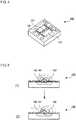
- Fig. 4 is a perspective view of an example sensor element used as the flow sensor and the physical property obtaining unit.
- Fig. 5 is a cross-sectional view of the sensor element illustrating its mechanism.
- a sensor element 100 includes a microheater (heater) 101 and thermopiles (temperature sensors) 102 arranged on both sides of the microheater 101. These components are sandwiched between upper and lower insulating thin films, and mounted on a silicon base. The silicon base has a cavity (opening) under the microheater 101 and the thermopiles 102.
- the microheater 101 may be a polysilicon resistor.
- the control unit 13 in Fig. 1 which is an arithmetic unit such as a microcontroller, calculates the flow rate based on an output from the flow sensor 11, calculates a characteristic value of a predetermined physical property based on an output from the physical property sensor 12, and corrects the flow rate using the characteristic value.
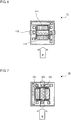
- the flow sensor 11 includes a first thermopile (flow-sensor first temperature sensor) 111 and a second thermopile (flow-sensor second temperature sensor) 112, which each sense the temperature of a measurement target fluid, and a microheater 113, which heats a measurement target fluid.
- the microheater 113, the flow-sensor first temperature sensor 111, and the flow-sensor second temperature sensor 112 are arranged parallel to one another inside the flow sensor 11 in flow direction P of the measurement target fluid.
- the microheater 113, the flow-sensor first temperature sensor 111, and the flow-sensor second temperature sensor 112 each are substantially rectangular as viewed from above, and have their longitudinal direction orthogonal to flow direction P of the target fluid.
- the flow-sensor first temperature sensor 111 is located upstream from the microheater 113, and the flow-sensor second temperature sensor 112 is located downstream to sense the temperatures at symmetrical positions with respect to the microheater 113.
- the physical property sensor 12 and the flow sensor 11 have substantially the same sensor structure, and have 90-degree different orientations with respect to the flow direction of the measurement target fluid.
- One of the sensors with the same structure can thus function as the physical property sensor 12 and the other sensor can function as the flow sensor 11. This reduces the manufacturing costs for the flow measurement device 1.
- the physical property sensor 12 includes a first thermopile (physical-property-sensor first temperature sensor) 121 and a second thermopile (physical-property-sensor second temperature sensor) 122, which each sense the temperature of a measurement target fluid, and a microheater (physical-property-sensor heater) 123, which heats the measurement target fluid.
- the physical-property-sensor heater 123, the physical-property-sensor first temperature sensor 121, and the physical-property-sensor second temperature sensor 122 are arranged parallel to one another inside the physical property sensor 12 in the direction orthogonal to flow direction Q of the measurement target fluid.
- the physical-property-sensor heater 123 With the physical-property-sensor heater 123 having its longitudinal direction in the flow direction of the measurement target fluid, the physical-property-sensor heater 123 can heat the measurement target fluid over a wide range in the flow direction of the measurement target fluid.
- the physical-property-sensor first temperature sensor 121 and the physical-property-sensor second temperature sensor 122 have output characteristics with smaller changes.
- the temperature distribution change caused by the measurement target fluid flow can have less effect, thus improving the sensing accuracy of the physical property sensor 12.
- the flow sensor 11 senses the flow rate of the measurement target fluid based on temperature sensing signals output from the flow-sensor first temperature sensor 111 and the flow-sensor second temperature sensor 112. More specifically, the flow sensor 11 calculates the difference between a temperature sensing signal output from the flow-sensor first temperature sensor 111 and a temperature sensing signal output from the flow-sensor second temperature sensor 112, and determines the flow rate value of the measurement target fluid based on the difference. The flow sensor 11 then outputs the flow rate value to the control unit 13.
- the physical property sensor 12 outputs temperature sensing signals output from the physical-property-sensor first temperature sensor 121 and the physical-property-sensor second temperature sensor 122 to a characteristic-value calculator 132. More specifically, the physical property sensor 12 determines the average value of the temperature sensing signals output from the physical-property-sensor first temperature sensor 121 and the physical-property-sensor second temperature sensor 122.
- the physical-property-sensor heater 123 changes the temperature as controlled by, for example, the control unit 13. This allows the physical-property-sensor first temperature sensor 121 and the physical-property-sensor second temperature sensor 122 to determine output values obtained before and after the change in the temperature of the physical-property-sensor heater 123.
- the physical property sensor 12 outputs the determined output values to the control unit 13.
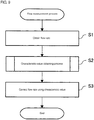
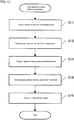
- Fig. 9 is a flowchart showing an example flow measurement process.
- the flow sensor 11 outputs temperature sensing signals from the flow-sensor first temperature sensor 111 and the flow-sensor second temperature sensor 112, and the flow rate calculator 133 calculates the flow rate of the measurement target fluid based on the two temperature sensing signals (S1 in Fig. 9 ).
- the flow sensor 11 outputs a temperature sensing signal output from the flow-sensor first temperature sensor 111 and a temperature sensing signal output from the flow-sensor second temperature sensor 112.
- the flow rate calculator 133 calculates the difference between the two temperature sensing signals, and calculates the flow rate value of the measurement target fluid based on the difference.
- any known technique may be used to calculate the flow rate of the measurement target fluid based on the temperature sensing signals output from the flow-sensor first temperature sensor 111 and the flow-sensor second temperature sensor 112.
- the flow sensor 11 outputs the calculated flow rate of the measurement target fluid to the control unit 13.
- the physical property sensor 12 performs a characteristic-value obtaining process (S2).
- S2 characteristic-value obtaining process
- the characteristic-value obtaining process will be described in detail with reference to Fig. 10 .
- Fig. 10 is a flowchart showing an example characteristic-value obtaining process.
- the characteristic-value calculator 132 in the control unit 13 causes the physical-property-sensor heater 123 in the physical property sensor 12 to heat at a first temperature (S11 in Fig. 10 ). Subsequently, the physical-property-sensor first temperature sensor 121 and the physical-property-sensor second temperature sensor 122 in the physical property sensor 12 sense the first temperature (S12). This step may be performed as controlled by, for example, the control unit 13.
- the rate of heat transfer through a measurement target fluid is determined in accordance with the physical properties including thermal conductivity, thermal diffusivity, and specific heat.
- the temperature differences between the physical-property-sensor heater 123, and the physical-property-sensor first temperature sensor 121 and the physical-property-sensor second temperature sensor 122 can be sensed to determine the thermal conductivity. For example, as the temperature differences between the physical-property-sensor heater 123, and the physical-property-sensor first temperature sensor 121 and the physical-property-sensor second temperature sensor 122 increase, the thermal conductivity decreases. Using such characteristics in this step, the physical-property-sensor first temperature sensor 121 and the physical-property-sensor second temperature sensor 122 located in the direction orthogonal to the flow direction of the measurement target fluid sense the temperature of the measurement target fluid.
- the characteristic-value calculator 132 in the control unit 13 then causes the physical-property-sensor heater 123 in the physical property sensor 12 to heat at a second temperature (S13). Subsequently, the physical-property-sensor first temperature sensor 121 and the physical-property-sensor second temperature sensor 122 in the physical property sensor 12 sense the second temperature (S14). This step may also be performed as controlled by, for example, the control unit 13. In this manner, the values are obtained to indicate the temperatures sensed by the physical-property-sensor first temperature sensor 121 and the physical-property-sensor second temperature sensor 122 before and after the change in the temperature of the physical-property-sensor heater 123.
- the characteristic-value calculator 132 also calculates the characteristic value using the sensed temperatures (S15). In this step, the sensor sensitivity ratio is determined.
- the sensor sensitivity ratio is the ratio of the sensor output value obtained by flowing a predetermined gas to the sensor output value obtained by flowing a reference gas, and the characteristic value indicating the thermal diffusivity.
- a change in temperature ( ⁇ T) sensed by the thermopiles when the heater temperature is changed may be used to determine the thermal diffusivity of the measurement target fluid.
- a flow rate output from a thermal flow sensor correlates with the thermal diffusivity.
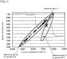
- Fig. 11 is a graph showing the sensor sensitivity ratio on the vertical axis and thermal conductivity on the horizontal axis.
- the thermal conductivity obtained as the physical property alone cannot be used to determine the sensor sensitivity ratio to be used for correction.
- the use of one set of a microheater heating temperature and a thermopile sensor temperature cannot allow appropriate correction for multiple gas groups based on two or more reference gases included in predetermined gas groups.
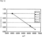
- Fig. 12 is a graph showing the sensor sensitivity ratio on the vertical axis and the temperature difference ⁇ T on the horizontal axis. For gases without linear approximation of the sensor sensitivity ratio and the thermal conductivity as shown in Fig. 11 , the sensor sensitivity ratio and the temperature difference ⁇ T are linearly approximated. The present embodiment thus allows correction for a gas group with an unknown thermal diffusivity.
- the flow sensors in the flow measurement device 1 are designed to measure a fluid in the main channel section 2.
- the present invention is not limited to this structure.
- the flow sensors in the flow measurement device 1 may be designed to measure a fluid in a sub-channel branching from the main channel section 2.
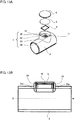
- Fig. 13A is an exploded perspective view of a flow measurement device 1 according to the present embodiment
- Fig. 13B is a cutaway view of the flow measurement device 1 shown in Fig. 13A
- the flow measurement device 1 according to this modification includes a main channel section 2, a sub-channel section 3, a seal 4, a circuit board 5, and a cover 6.
- the main channel section 2 is a tubular member having a through-hole in the longitudinal direction.
- the inner surface of the main channel section 2 has an inlet (first inlet) 34a upstream from target fluid flow direction O, and an outlet (first outlet) 35a downstream.
- the main channel section 2 has an axial length of about 50 mm, an inner surface diameter (inside diameter of the main channel section 2) of about 20 mm, and an outer diameter of about 24 mm.
- the sub-channel section 3 is located over the main channel section 2, and a sub-channel is formed inside and on the top surface of the sub-channel section 3.
- the sub-channel section 3 has one end continuous with the inlet 34a, and the other end continuous with the outlet 35a.
- the sub-channel section 3 in the flow measurement device 1 includes an in-flow channel 34, a physical property sensing channel 32, a flow sensing channel 33, and an out-flow channel 35.
- the in-flow channel 34 is intended for taking in a measurement target fluid flowing through the main channel section 2, and allowing the measurement target fluid to branch to the physical property sensing channel 32 and to the flow sensing channel 33.
- the in-flow channel 34 extends through the sub-channel section 3 in the direction orthogonal to the main channel section 2.
- the in-flow channel 34 has one end continuous with the inlet 34a, and the other end open through the top surface of the main channel section 2 and continuous with the physical property sensing channel 32 and the flow sensing channel 33. This structure allows part of the measurement target fluid flowing through the main channel section 2 to branch to the physical property sensing channel 32 and to the flow sensing channel 33 via the in-flow channel 34.
- the physical property sensing channel 32 has a longitudinal cross-section that is substantially squared U-shaped.
- the channel is formed on the top surface of the sub-channel section 3 and extends in the direction parallel to the main channel section 2.
- the physical property sensing channel 32 contains a physical property sensor 12 for sensing a physical property of the measurement target fluid in its longitudinally elongated part (in the direction parallel to the main channel section 2).
- the physical property sensing channel 32 has one end continuous with the inlet 34a via the in-flow channel 34, and the other end continuous with the outlet 35a via the out-flow channel 35.
- the flow sensing channel 33 has a longitudinal cross-section that is substantially squared U-shaped.
- the flow sensing channel 33 is formed on the top surface of the sub-channel section 3 and extends in the direction parallel to the main channel section 2.
- the flow sensing channel 33 contains a flow sensor 11 for sensing the flow rate of the measurement target fluid in its longitudinally elongated part (in the direction parallel to the main channel section 2).
- the flow sensing channel 33 has one end continuous with the inlet 34a via the in-flow channel 34, and the other end continuous with the outlet 35a via the out-flow channel 35.
- the physical property sensor 12 and the flow sensor 11 in the figure are separate from the circuit board 5 for ease of explanation, the physical property sensor 12 and the flow sensor 11 mounted on the circuit board 5 are located in the physical property sensing channel 32 and the flow sensing channel 33.
- the measurement target fluid taken in through the same inlet 34a branches to the physical property sensing channel 32 and to the flow sensing channel 33 to enable the physical property sensor 12 and the flow sensor 11 to sense the physical property and the flow rate based on the measurement target fluid flowing under the same conditions including temperature and concentration. This improves the measurement accuracy of the flow measurement device 1.
- the seal 4 is fitted in the sub-channel section 3, and then the circuit board 5 is placed.
- the circuit board 5 is fixed to the sub-channel section 3 with the cover 6. This structure hermetically seals the inside of the sub-channel section 3.
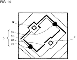
- Fig. 14 is a perspective view of the sub-channel section 3 shown in Fig. 13A .
- the physical property sensing channel 32 has one end that is substantially squared U-shaped continuous with the in-flow channel 34, and the other end continuous with the out-flow channel 35.
- the flow sensing channel 33 has one end that is substantially squared U-shaped continuous with the in-flow channel 34, and the other end continuous with the out-flow channel 35.
- the physical property sensing channel 32 and the flow sensing channel 33 are also continuous with each other at both their ends.
- the physical property sensing channel 32 and the flow sensing channel 33 define a rectangular channel on the top surface of the sub-channel section 3.
- the physical property sensing channel 32 and the flow sensing channel 33 each have a square area as viewed in the direction orthogonal to the top surface of the sub-channel section 3. These areas are located symmetrically with respect to the line connecting the in-flow channel 34 and the out-flow channel 35.
- the physical property sensing channel 32 and the flow sensing channel 33 in the present embodiment each have a square area, the present invention is not limited to the present embodiment.
- the physical property sensing channel 32 and the flow sensing channel 33 may have any shape that may contain the physical property sensor 12 or the flow sensor 11 and may have the shape determined by the shapes of the physical property sensor 12 and the flow sensor 11 to be mounted.
- Fig. 15A is a schematic top view of the physical property sensor 12 shown in Fig. 13 .
- Fig. 15B is a schematic top view of the flow sensor 11 shown in Fig. 13 .
- the physical property sensing channel 32 and the flow sensing channel 33 have longitudinally extending channel portions with different widths.
- the channel portion of the physical property sensing channel 32 containing the physical property sensor 12 have a smaller width than the channel portion of the flow sensing channel 33 containing the flow sensor 11.
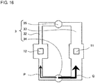
- Fig. 16 is a schematic diagram describing the flow rates of the measurement target fluid branching to the physical property sensing channel 32 and to the flow sensing channel 33 shown in Fig. 13 .
- the physical property sensing channel 32 has a width that allows a branched portion of the target fluid to flow at flow rate P
- the flow sensing channel 33 has a width that allows a branched portion of the target fluid to flow at flow rate Q.
- Flow rate P and flow rate Q vary depending on the flow rate of the measurement target fluid flowing through the main channel section 2.
- the width of the physical property sensing channel 32 is determined to regulate flow rate P within the sensing range of the physical property sensor 12
- the width of the flow sensing channel 33 is determined to regulate flow rate Q within the sensing range of the flow sensor 11.
- the physical property sensing channel 32 has a width of about 0.4 mm, and the flow sensing channel 33 has a width of about 0.8 mm.
- the flow measurement device 1 enables individual control of the flow rates of the measurement target fluid branching to the physical property sensing channel 32 and to the flow sensing channel 33 by adjusting the width of each channel.
- the flow rate of the measurement target fluid flowing through the physical property sensing channel 32 can be controlled within the sensing range of the physical property sensor 12, and the flow rate of the measurement target fluid flowing through the flow sensing channel 33 can be controlled within the sensing range of the flow sensor 11.
- the physical property sensor 12 which can sense a physical property of the measurement target fluid at the optimum flow rate within its specific sensing range, has higher sensing accuracy.
- the flow sensor 11 which can sense the flow rate of the measurement target fluid at the optimum flow rate within its specific sensing range, has higher sensing accuracy.
- each of the physical property sensing channel 32 and the flow sensing channel 33 is substantially squared U-shaped as shown in Fig. 16 .
- the present invention is not limited to this example.
- the physical property sensing channel 32 and the flow sensing channel 33 may each have any shape having a width that enables control of the flow rate of the measurement target fluid flowing through the physical property sensing channel 32 and the flow sensing channel 33.
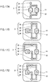
- Figs. 17A to 17D are top views each showing a physical property sensing channel 32 and a flow sensing channel 33 according to modifications formed on the top surface of the sub-channel section 3 shown in Fig. 16 .
- the physical property sensing channel 32 may be linear, and the flow sensing channel 33 may be substantially squared U-shaped.
- the physical property sensing channel 32 may be formed to receive a measurement target fluid flowing in the direction orthogonal to the flow direction of the measurement target fluid into the flow sensing channel 33.
- the physical property sensor 12 and the flow sensor 11 may have the same orientation. This simplifies the process of mounting the physical property sensor 12 and the flow sensor 11 on the circuit board 5 in the manufacturing processes for the flow measurement device 1.
- the physical property sensor 12 includes the physical-property-sensor heater 123 for heating a measurement target fluid, and the physical-property-sensor first temperature sensor 121 and the physical-property-sensor second temperature sensor 122 for sensing the temperature of the measurement target fluid.
- the physical-property-sensor first temperature sensor 121 and the physical-property-sensor second temperature sensor 122 are symmetric with respect to the physical-property-sensor heater 123.
- the present invention is not limited to this structure.
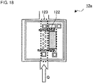
- Fig. 18 is a schematic top view of a physical property sensor 12 according to a modification of the structure shown in Fig. 15A .
- the physical-property-sensor heater 123 and the physical-property-sensor first temperature sensor 121 may form a physical property sensor 12a without the physical-property-sensor first temperature sensor 121 .
- the physical-property-sensor heater and the physical-property-sensor first temperature sensor arranged parallel in the direction orthogonal to the flow direction of the measurement target fluid may form the physical property sensor 12a.
- a flow measurement device according to another modification of the embodiment will now be described with reference to Figs. 19A to 19C .
- the corresponding components as in the above embodiment are given the corresponding reference numerals, and will not be described.
- the flow measurement device includes a flow sensor contained in the main channel.
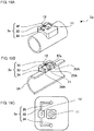
- Fig. 19A is a perspective view of a flow measurement device 1a according to the present modification.
- Fig. 19B is a cross-sectional view of the flow measurement device 1a shown in Fig. 19A.
- Fig. 19C is a top view of a sub-channel section 3a shown in Fig. 19A .
- the flow measurement device 1a has an opening 37A between an inlet 34A and an outlet 35A in the inner surface of a main channel section 3A.
- the sub-channel section 3a has a cellular flow sensing channel 37a containing a flow sensor 11.
- the flow sensing channel 37a is continuous with the opening 37A.
- the opening 37A allows a measurement target fluid flowing through the main channel section 2a to flow into the flow sensing channel 37a.
- the flow sensor 11 senses the flow rate of the measurement target fluid.
- the size of the opening 37A may be adjusted to control the flow rate of the measurement target fluid flowing into the flow sensing channel 37a from the main channel section 2a.
Landscapes
- Physics & Mathematics (AREA)
- General Physics & Mathematics (AREA)
- Fluid Mechanics (AREA)
- Analytical Chemistry (AREA)
- Life Sciences & Earth Sciences (AREA)
- Chemical & Material Sciences (AREA)
- Health & Medical Sciences (AREA)
- Biochemistry (AREA)
- General Health & Medical Sciences (AREA)
- Immunology (AREA)
- Pathology (AREA)
- Engineering & Computer Science (AREA)
- Aviation & Aerospace Engineering (AREA)
- Measuring Volume Flow (AREA)
- Investigating Or Analyzing Materials Using Thermal Means (AREA)
Abstract
Description
- The present invention relates to a flow measurement device, a flow measurement method, and a flow measurement program.
- Flow measurement devices are known to include a heater and a temperature sensor and measure the flow rate of a measurement target fluid. For example,
Patent Literature 1 describes a flow measurement device including a physical property sensor for sensing the physical properties of a measurement target fluid to reduce variations in output characteristics caused by changes in the physical properties of the measurement target fluid. More specifically, the temperature differences between a microheater and thermopiles are sensed to determine the thermal conductivity (thermal diffusion constant), and the flow rate measured by a sensor is then corrected based on the thermal conductivity. - Patent Literature 1: Japanese Unexamined Patent Application Publication No.
2012-233776 - A technique has been developed to determine the thermal conductivity based on the temperature differences between a microheater and thermopiles and correct the flow rate of a measurement target fluid using the thermal conductivity. With a thermal flow sensor, the thermal diffusivity of the measurement target fluid also affects the sensor output. Thus, the technique known in the art may not accurately correct the flow rate depending on the gas.
- One or more aspects of the present invention are directed to improving the accuracy in measuring the flow rate of measurement target fluids having different thermal diffusivities.
- A flow measurement device according to one aspect of the present invention includes a flow sensor that senses a flow rate of a measurement target fluid flowing through a main channel, a characteristic-value obtaining unit that includes a heater for heating the measurement target fluid and a temperature sensor for sensing a temperature of the measurement target fluid, and obtains a characteristic value of the measurement target fluid, and a flow rate correction unit that corrects a flow rate of the measurement target fluid calculated based on a sensing signal output from the flow sensor using the characteristic value of the measurement target fluid obtained by the characteristic-value obtaining unit. The heater and the temperature sensor are arranged parallel to each other in a direction orthogonal to a flow direction of the measurement target fluid. The characteristic-value obtaining unit obtains the characteristic value based on a difference between the temperatures of the measurement target fluid sensed by the temperature sensor before and after a temperature of the heater is changed.
- The characteristic value obtained based on the difference between the measurement target fluid temperatures sensed by the temperature sensor before and after the change in the heater temperature allows correction in accordance with the thermal diffusivity varying depending on, for example, the thermal conductivity, the specific heat, and the viscosity of the measurement target fluid. Thus, the flow rate of measurement target fluids having different thermal diffusivities can be measured with higher accuracy.
- The characteristic value may be a value obtained by multiplying a predetermined coefficient by the difference between the temperatures of the measurement target fluid sensed by the temperature sensor before and after the temperature of the heater is changed. The flow rate correction unit may multiply the sensing signal output from the flow sensor by the characteristic value to correct the flow rate of the measurement target fluid. This value may be specifically used as a characteristic value.
- The flow measurement device may further include a sub-channel section branching from the main channel and having one end continuous with a first inlet opening in the main channel and another end continuous with a first outlet opening in the main channel. The sub-channel section includes a characteristic-value sensing channel containing the temperature sensor included in the characteristic-value obtaining unit. The flow sensor may be at a position different from the characteristic-value sensing channel. The sub-channel section enables the device to measure the flow rate independently of the size of and the flow rate in the main channel. Additionally, the sub-channel section prevents dust from entering the flow sensor and the temperature sensor included in the characteristic-value obtaining unit.
- Further, the temperature sensor included in the characteristic-value obtaining unit and the flow sensor may be included in a flow sensing member that is removably mounted on the main channel or a member defining the sub-channel section. This enables a component mountable to main channel sections with various flow rates and shapes, and reduces the costs.
- Further, the sub-channel section may include a flow sensing channel containing the flow sensor, a first sub-channel section branching from the sub-channel section and having one end continuous with a first inlet opening in the main channel and another end continuous with a first outlet opening in the main channel, and a second sub-channel section branching from the first sub-channel section and having one end continuous with a second inlet opening in the first sub-channel section and another end continuous with a second outlet opening in the first sub-channel section. Each of the flow sensing channel and the characteristic-value sensing channel may further branch from the second sub-channel section and have one end continuous with a third inlet opening in the second sub-channel section and another end continuous with a third outlet opening in the second sub-channel section. This triple branching structure further reduces dust entering the flow sensor and the temperature sensor included in the characteristic-value obtaining unit.
- The sub-channel section may further include a flow sensing channel containing the flow sensor. The flow sensing channel may have one end continuous with the first inlet and another end continuous with the first outlet. The device may allow the measurement target fluid flowing in through the first inlet to branch to the characteristic-value sensing channel and to the flow sensing channel. This specific branching structure may be used.
- The sub-channel section may further include a flow sensing channel containing the flow sensor. The characteristic-value sensing channel may be located in the flow sensing channel. The device may allow part of the measurement target fluid flowing through the flow sensing channel to flow into the characteristic-value sensing channel. This specific branching structure may be used.
- The sub-channel section may further include a flow sensing channel containing the flow sensor. The flow sensing channel may have one end continuous with a fourth inlet opening in the main channel and another end continuous with a fourth outlet opening in the main channel. This specific branching structure may be used.
- The flow sensor may be located in the main channel. In this manner, the flow sensor may measure a fluid in the main channel.
- The heater may be located to have a longitudinal direction in the flow direction of the measurement target fluid. The heater located in this manner can heat the measurement target fluid over a wide range in the flow direction of the measurement target fluid.
- The temperature sensor may be located to have a longitudinal direction in the flow direction of the measurement target fluid. The temperature sensor located in this manner can sense the temperature over a wide range in the flow direction of the measurement target fluid.
- The sub-channel section may further include a flow sensing channel containing the flow sensor. The flow sensing channel and the characteristic-value sensing channel may be defined by the sub-channel section or a channel branching from the sub-channel section separated by a circuit board located in parallel with the flow direction of the measurement target fluid in the sub-channel section or the channel branching from the sub-channel section. The flow sensor may be located on a first surface of the circuit board and the temperature sensor included in the characteristic-value obtaining unit is located on a second surface of the circuit board opposite to the first surface. This specific branching structure may be used.
- The aspects described in the solution to the problem section may be combined to the extent possible without departing from the objects and the technical idea of the present invention. The flow measurement device described in the solution to the problem section may be embodied as a method or a program implemented by a processor or a microcontroller.
- One or more aspects of the present invention improve the accuracy in measuring the flow rate of measurement target fluids having different thermal diffusivities.
-
-
Fig. 1 is a perspective view of a flow measurement device showing its structure. -
Fig. 2 is a longitudinal cross-sectional view of the flow measurement device. -
Fig. 3 is a cross-sectional view of the flow measurement device. -
Fig. 4 is a perspective view of an example sensor element used as a flow sensor and a physical property obtaining unit. -
Fig. 5 is a cross-sectional view of the sensor element illustrating its mechanism. -
Fig. 6 is a schematic top view of the flow sensor. -
Fig. 7 is a schematic top view of the physical property obtaining unit. -
Fig. 8 is a functional block diagram of the flow measurement device. -
Fig. 9 is a flowchart showing an example flow measurement process. -
Fig. 10 is a flowchart showing an example characteristic-value obtaining process. -
Fig. 11 is a graph showing the sensor sensitivity ratio on the vertical axis and thermal conductivity on the horizontal axis. -
Fig. 12 is a graph showing the sensor sensitivity ratio on the vertical axis and the temperature difference ΔT on the horizontal axis. -
Figs. 13A and 13B are diagrams showing a flow measurement device. -
Fig. 14 is a perspective view of a sub-channel section. -
Fig. 15A is a schematic diagram of a physical property sensor, andFig. 15B is a schematic diagram of a flow sensor. -
Fig. 16 is a schematic diagram describing the flow rate of a measurement target fluid branching to a physical property sensing channel and to a flow sensing channel. -
Figs. 17A to 17D are top views of a physical property sensing channel and a flow sensing channel according to modifications formed on the top surface of the sub-channel section. -
Fig. 18 is a schematic top view of a physical property sensor according to a modification. -
Fig. 19A is a perspective view of a flow measurement device,Fig. 19B is a cross-sectional view of the flow measurement device, andFig. 19C is a top view of an auxiliary channel section. -
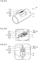
Figs. 20A and 20B are diagrams showing a flow measurement device according to another embodiment. -
Figs. 21A to 21C are diagrams showing a flow measurement device according to still another embodiment. -
Figs. 22A to 22C are diagrams describing multiple branches according to another modification. -
Fig. 23 is a cross-sectional view describing another modification. - A flow measurement device according to one embodiment of the present invention will now be described with reference to the drawings. The embodiment described below is an example of a flow measurement device. The flow measurement device according to one or more embodiments is not limited to the structure described below.
-
Fig. 1 is a perspective view of the flow measurement device according to the present embodiment showing its structure.Fig. 2 is a longitudinal cross-sectional view of the flow measurement device.Fig. 3 is a cross-sectional view of the flow measurement device. The flow measurement device is incorporated in, for example, a gas meter, a burning appliance, an automobile internal combustion engine, or a fuel cell, and measures the amount of gas flowing through a channel. InFig. 1 , a dashed arrow indicates the direction of a fluid flow. As shown inFigs. 1 to 3 , aflow measurement device 1 in the present embodiment is installed inside amain channel section 2. Theflow measurement device 1 includes aflow sensor 11, a physical property sensor (or temperature sensor) 12, and acontrol unit 13. Theflow sensor 11 and thephysical property sensor 12 are thermal flow sensors including a heater that is a microheater and temperature sensors that are thermopiles. -
Fig. 4 is a perspective view of an example sensor element used as the flow sensor and the physical property obtaining unit.Fig. 5 is a cross-sectional view of the sensor element illustrating its mechanism. Asensor element 100 includes a microheater (heater) 101 and thermopiles (temperature sensors) 102 arranged on both sides of themicroheater 101. These components are sandwiched between upper and lower insulating thin films, and mounted on a silicon base. The silicon base has a cavity (opening) under themicroheater 101 and thethermopiles 102. Themicroheater 101 may be a polysilicon resistor. InFig. 5 , themicroheater 101 generates heat with the temperature distribution schematically indicated by dashed ellipses, of which a thicker line indicates a higher temperature. With no airflow, the temperature distribution across themicroheater 101 is substantially uniform as shown in the upper part (1) ofFig. 5 . With an airflow in, for example, the direction indicated by a dashed arrow in the lower part (2) ofFig. 5 , the ambient air moves and the temperature becomes higher on the leeward side of themicroheater 101 than on the windward side. The sensor element outputs the flow rate value based on the bias in the distribution of the heat from the heater. - The
control unit 13 inFig. 1 , which is an arithmetic unit such as a microcontroller, calculates the flow rate based on an output from theflow sensor 11, calculates a characteristic value of a predetermined physical property based on an output from thephysical property sensor 12, and corrects the flow rate using the characteristic value. - Flow Sensor and Physical Property Obtaining Unit
-
Fig. 6 is a schematic top view of theflow sensor 11 shown inFig. 1 .Fig. 7 is a schematic top view of thephysical property sensor 12 shown inFig. 1 . - As shown in
Fig. 6 , theflow sensor 11 includes a first thermopile (flow-sensor first temperature sensor) 111 and a second thermopile (flow-sensor second temperature sensor) 112, which each sense the temperature of a measurement target fluid, and amicroheater 113, which heats a measurement target fluid. Themicroheater 113, the flow-sensorfirst temperature sensor 111, and the flow-sensorsecond temperature sensor 112 are arranged parallel to one another inside theflow sensor 11 in flow direction P of the measurement target fluid. Themicroheater 113, the flow-sensorfirst temperature sensor 111, and the flow-sensorsecond temperature sensor 112 each are substantially rectangular as viewed from above, and have their longitudinal direction orthogonal to flow direction P of the target fluid. - The flow-sensor
first temperature sensor 111 is located upstream from themicroheater 113, and the flow-sensorsecond temperature sensor 112 is located downstream to sense the temperatures at symmetrical positions with respect to themicroheater 113. - In the
flow measurement device 1, thephysical property sensor 12 and theflow sensor 11 have substantially the same sensor structure, and have 90-degree different orientations with respect to the flow direction of the measurement target fluid. One of the sensors with the same structure can thus function as thephysical property sensor 12 and the other sensor can function as theflow sensor 11. This reduces the manufacturing costs for theflow measurement device 1. - As shown in
Fig. 7 , thephysical property sensor 12 includes a first thermopile (physical-property-sensor first temperature sensor) 121 and a second thermopile (physical-property-sensor second temperature sensor) 122, which each sense the temperature of a measurement target fluid, and a microheater (physical-property-sensor heater) 123, which heats the measurement target fluid. The physical-property-sensor heater 123, the physical-property-sensorfirst temperature sensor 121, and the physical-property-sensorsecond temperature sensor 122 are arranged parallel to one another inside thephysical property sensor 12 in the direction orthogonal to flow direction Q of the measurement target fluid. The physical-property-sensor heater 123, the physical-property-sensorfirst temperature sensor 121, and the physical-property-sensorsecond temperature sensor 122 each are substantially rectangular as viewed from above, and have their longitudinal direction in flow direction Q of the measurement target fluid. The physical-property-sensorfirst temperature sensor 121 and the physical-property-sensorsecond temperature sensor 122 are located symmetrically with respect to the physical-property-sensor heater 123 to sense the temperatures at symmetrical positions with respect to the physical-property-sensor heater 123. - The flow of the measurement target fluid biases the temperature distribution downstream, and thus a change in the temperature distribution in the direction orthogonal to the flow direction is smaller than a change in the temperature distribution in the flow direction of the measurement target fluid. Thus, the parallel arrangement of the physical-property-sensor
first temperature sensor 121, the physical-property-sensor heater 123, and the physical-property-sensorsecond temperature sensor 122 in this order in the direction orthogonal to the flow direction of the measurement target fluid reduces a change in the output characteristics of the physical-property-sensorfirst temperature sensor 121 and the physical-property-sensorsecond temperature sensor 122 caused by a change in the temperature distribution. The temperature distribution change caused by the measurement target fluid flow can have less effect, thus improving the sensing accuracy of thephysical property sensor 12. - With the physical-property-
sensor heater 123 having its longitudinal direction in the flow direction of the measurement target fluid, the physical-property-sensor heater 123 can heat the measurement target fluid over a wide range in the flow direction of the measurement target fluid. Thus, with the temperature distribution biased downstream by the flow of a measurement target fluid, the physical-property-sensorfirst temperature sensor 121 and the physical-property-sensorsecond temperature sensor 122 have output characteristics with smaller changes. The temperature distribution change caused by the measurement target fluid flow can have less effect, thus improving the sensing accuracy of thephysical property sensor 12. - Additionally, with the physical-property-sensor
first temperature sensor 121 and the physical-property-sensorsecond temperature sensor 122 having their longitudinal directions in the flow direction of the measurement target fluid, the physical-property-sensorfirst temperature sensor 121 and the physical-property-sensorsecond temperature sensor 122 can sense the temperature over a wide range in the flow direction of the measurement target fluid. Thus, with the temperature distribution biased downstream by the flow of a measurement target fluid, the physical-property-sensorfirst temperature sensor 121 and the physical-property-sensorsecond temperature sensor 122 have output characteristics with smaller changes. The temperature distribution change caused by the measurement target fluid flow can have less effect, thus improving the sensing accuracy of thephysical property sensor 12. -
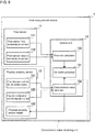
Fig. 8 is a functional block diagram of the flow measurement device. Theflow measurement device 1 includes theflow sensor 11, thephysical property sensor 12, and thecontrol unit 13. Theflow sensor 11 includes the flow-sensorfirst temperature sensor 111 and the flow-sensorsecond temperature sensor 112. Thephysical property sensor 12 includes the physical-property-sensorfirst temperature sensor 121, the physical-property-sensorsecond temperature sensor 122, and the physical-property-sensor heater 123. - The
flow sensor 11 senses the flow rate of the measurement target fluid based on temperature sensing signals output from the flow-sensorfirst temperature sensor 111 and the flow-sensorsecond temperature sensor 112. More specifically, theflow sensor 11 calculates the difference between a temperature sensing signal output from the flow-sensorfirst temperature sensor 111 and a temperature sensing signal output from the flow-sensorsecond temperature sensor 112, and determines the flow rate value of the measurement target fluid based on the difference. Theflow sensor 11 then outputs the flow rate value to thecontrol unit 13. - The
physical property sensor 12 outputs temperature sensing signals output from the physical-property-sensorfirst temperature sensor 121 and the physical-property-sensorsecond temperature sensor 122 to a characteristic-value calculator 132. More specifically, thephysical property sensor 12 determines the average value of the temperature sensing signals output from the physical-property-sensorfirst temperature sensor 121 and the physical-property-sensorsecond temperature sensor 122. The physical-property-sensor heater 123 changes the temperature as controlled by, for example, thecontrol unit 13. This allows the physical-property-sensorfirst temperature sensor 121 and the physical-property-sensorsecond temperature sensor 122 to determine output values obtained before and after the change in the temperature of the physical-property-sensor heater 123. Thephysical property sensor 12 outputs the determined output values to thecontrol unit 13. - The
control unit 13 includes acorrection processor 131, the characteristic-value calculator 132, and aflow rate calculator 133. Theflow rate calculator 133 calculates the flow rate of the measurement target fluid based on the sensing value received from theflow sensor 11. The characteristic-value calculator 132 calculates the characteristic value based on the sensing value received from thephysical property sensor 12. More specifically, the characteristic-value calculator 132 changes the temperature of the microheater in thephysical property sensor 12, and multiplies a predetermined coefficient by the difference between the measurement target fluid temperatures sensed by the thermopiles before and after the change to calculate the characteristic value. Thecorrection processor 131 uses the characteristic value to correct the flow rate calculated by theflow rate calculator 133. Thephysical property sensor 12 and the characteristic-value calculator 132 are also collectively referred to as a characteristic-value obtaining unit. -
Fig. 9 is a flowchart showing an example flow measurement process. As shown inFig. 9 , theflow sensor 11 outputs temperature sensing signals from the flow-sensorfirst temperature sensor 111 and the flow-sensorsecond temperature sensor 112, and theflow rate calculator 133 calculates the flow rate of the measurement target fluid based on the two temperature sensing signals (S1 inFig. 9 ). - More specifically, the
flow sensor 11 outputs a temperature sensing signal output from the flow-sensorfirst temperature sensor 111 and a temperature sensing signal output from the flow-sensorsecond temperature sensor 112. Theflow rate calculator 133 calculates the difference between the two temperature sensing signals, and calculates the flow rate value of the measurement target fluid based on the difference. - Any known technique may be used to calculate the flow rate of the measurement target fluid based on the temperature sensing signals output from the flow-sensor
first temperature sensor 111 and the flow-sensorsecond temperature sensor 112. Theflow sensor 11 outputs the calculated flow rate of the measurement target fluid to thecontrol unit 13. - The
physical property sensor 12 performs a characteristic-value obtaining process (S2). The characteristic-value obtaining process will be described in detail with reference toFig. 10 . -
Fig. 10 is a flowchart showing an example characteristic-value obtaining process. The characteristic-value calculator 132 in thecontrol unit 13 causes the physical-property-sensor heater 123 in thephysical property sensor 12 to heat at a first temperature (S11 inFig. 10 ). Subsequently, the physical-property-sensorfirst temperature sensor 121 and the physical-property-sensorsecond temperature sensor 122 in thephysical property sensor 12 sense the first temperature (S12). This step may be performed as controlled by, for example, thecontrol unit 13. The rate of heat transfer through a measurement target fluid is determined in accordance with the physical properties including thermal conductivity, thermal diffusivity, and specific heat. The temperature differences between the physical-property-sensor heater 123, and the physical-property-sensorfirst temperature sensor 121 and the physical-property-sensorsecond temperature sensor 122 can be sensed to determine the thermal conductivity. For example, as the temperature differences between the physical-property-sensor heater 123, and the physical-property-sensorfirst temperature sensor 121 and the physical-property-sensorsecond temperature sensor 122 increase, the thermal conductivity decreases. Using such characteristics in this step, the physical-property-sensorfirst temperature sensor 121 and the physical-property-sensorsecond temperature sensor 122 located in the direction orthogonal to the flow direction of the measurement target fluid sense the temperature of the measurement target fluid. - The characteristic-
value calculator 132 in thecontrol unit 13 then causes the physical-property-sensor heater 123 in thephysical property sensor 12 to heat at a second temperature (S13). Subsequently, the physical-property-sensorfirst temperature sensor 121 and the physical-property-sensorsecond temperature sensor 122 in thephysical property sensor 12 sense the second temperature (S14). This step may also be performed as controlled by, for example, thecontrol unit 13. In this manner, the values are obtained to indicate the temperatures sensed by the physical-property-sensorfirst temperature sensor 121 and the physical-property-sensorsecond temperature sensor 122 before and after the change in the temperature of the physical-property-sensor heater 123. - The characteristic-
value calculator 132 also calculates the characteristic value using the sensed temperatures (S15). In this step, the sensor sensitivity ratio is determined. The sensor sensitivity ratio is the ratio of the sensor output value obtained by flowing a predetermined gas to the sensor output value obtained by flowing a reference gas, and the characteristic value indicating the thermal diffusivity. The sensor sensitivity ratio α is determined usingFormula 1 below.
- In this formula, β is a predetermined coefficient, and ΔT is the difference between the sensing values output from the physical-property-sensor
first temperature sensor 121 and the physical-property-sensorsecond temperature sensor 122 before and after the change in the temperature of the physical-property-sensor heater 123. - Referring back to the process shown in
Fig. 9 , thecontrol unit 13 then corrects the flow rate of the measurement target fluid calculated by the flow rate calculator using the characteristic value (S3 inFig. 9 ). More specifically, thecontrol unit 13 calculates a corrected flowrate using Formula 2 below.
- In the present embodiment, a change in temperature (ΔT) sensed by the thermopiles when the heater temperature is changed may be used to determine the thermal diffusivity of the measurement target fluid. A flow rate output from a thermal flow sensor correlates with the thermal diffusivity. Thus, the flow rate correction process according to the present embodiment enables appropriate correction for every gas. More specifically, the flow rate of measurement target fluids having different thermal diffusivities can be measured with higher accuracy.
-
Fig. 11 is a graph showing the sensor sensitivity ratio on the vertical axis and thermal conductivity on the horizontal axis. For different gas groups having different physical properties other than thermal conductivity as shown inFig. 11 , for example, for mixed gases with different compositions, the thermal conductivity obtained as the physical property alone cannot be used to determine the sensor sensitivity ratio to be used for correction. In other words, the use of one set of a microheater heating temperature and a thermopile sensor temperature cannot allow appropriate correction for multiple gas groups based on two or more reference gases included in predetermined gas groups. -
Fig. 12 is a graph showing the sensor sensitivity ratio on the vertical axis and the temperature difference ΔT on the horizontal axis. For gases without linear approximation of the sensor sensitivity ratio and the thermal conductivity as shown inFig. 11 , the sensor sensitivity ratio and the temperature difference ΔT are linearly approximated. The present embodiment thus allows correction for a gas group with an unknown thermal diffusivity. - In the above embodiment, the flow sensors in the
flow measurement device 1 are designed to measure a fluid in themain channel section 2. However, the present invention is not limited to this structure. For example, the flow sensors in theflow measurement device 1 may be designed to measure a fluid in a sub-channel branching from themain channel section 2. -
Fig. 13A is an exploded perspective view of aflow measurement device 1 according to the present embodiment, andFig. 13B is a cutaway view of theflow measurement device 1 shown inFig. 13A . As shown inFigs. 13A and 13B , theflow measurement device 1 according to this modification includes amain channel section 2, asub-channel section 3, aseal 4, acircuit board 5, and acover 6. - The
main channel section 2 is a tubular member having a through-hole in the longitudinal direction. The inner surface of themain channel section 2 has an inlet (first inlet) 34a upstream from target fluid flow direction O, and an outlet (first outlet) 35a downstream. - In the present embodiment, the
main channel section 2 has an axial length of about 50 mm, an inner surface diameter (inside diameter of the main channel section 2) of about 20 mm, and an outer diameter of about 24 mm. - The
sub-channel section 3 is located over themain channel section 2, and a sub-channel is formed inside and on the top surface of thesub-channel section 3. Thesub-channel section 3 has one end continuous with theinlet 34a, and the other end continuous with theoutlet 35a. Thesub-channel section 3 in theflow measurement device 1 includes an in-flow channel 34, a physicalproperty sensing channel 32, aflow sensing channel 33, and an out-flow channel 35. - The in-
flow channel 34 is intended for taking in a measurement target fluid flowing through themain channel section 2, and allowing the measurement target fluid to branch to the physicalproperty sensing channel 32 and to theflow sensing channel 33. The in-flow channel 34 extends through thesub-channel section 3 in the direction orthogonal to themain channel section 2. The in-flow channel 34 has one end continuous with theinlet 34a, and the other end open through the top surface of themain channel section 2 and continuous with the physicalproperty sensing channel 32 and theflow sensing channel 33. This structure allows part of the measurement target fluid flowing through themain channel section 2 to branch to the physicalproperty sensing channel 32 and to theflow sensing channel 33 via the in-flow channel 34. - The physical
property sensing channel 32 has a longitudinal cross-section that is substantially squared U-shaped. The channel is formed on the top surface of thesub-channel section 3 and extends in the direction parallel to themain channel section 2. The physicalproperty sensing channel 32 contains aphysical property sensor 12 for sensing a physical property of the measurement target fluid in its longitudinally elongated part (in the direction parallel to the main channel section 2). The physicalproperty sensing channel 32 has one end continuous with theinlet 34a via the in-flow channel 34, and the other end continuous with theoutlet 35a via the out-flow channel 35. - The
flow sensing channel 33 has a longitudinal cross-section that is substantially squared U-shaped. Theflow sensing channel 33 is formed on the top surface of thesub-channel section 3 and extends in the direction parallel to themain channel section 2. Theflow sensing channel 33 contains aflow sensor 11 for sensing the flow rate of the measurement target fluid in its longitudinally elongated part (in the direction parallel to the main channel section 2). Theflow sensing channel 33 has one end continuous with theinlet 34a via the in-flow channel 34, and the other end continuous with theoutlet 35a via the out-flow channel 35. - Although the
physical property sensor 12 and theflow sensor 11 in the figure are separate from thecircuit board 5 for ease of explanation, thephysical property sensor 12 and theflow sensor 11 mounted on thecircuit board 5 are located in the physicalproperty sensing channel 32 and theflow sensing channel 33. - The out-
flow channel 35 is intended for discharging the measurement target fluid that has passed through the physicalproperty sensing channel 32 and theflow sensing channel 33 into themain channel section 2. The out-flow channel 35 extends through thesub-channel section 3 in the direction orthogonal to themain channel section 2. The out-flow channel 35 has one end continuous with theoutlet 35a, and the other end open through the top surface of themain channel section 2 and continuous with the physicalproperty sensing channel 32 and theflow sensing channel 33. This structure allows the measurement target fluid that has passed through the physicalproperty sensing channel 32 and theflow sensing channel 33 to be discharged into themain channel section 2 via the out-flow channel 35. - In this manner, the measurement target fluid taken in through the
same inlet 34a branches to the physicalproperty sensing channel 32 and to theflow sensing channel 33 to enable thephysical property sensor 12 and theflow sensor 11 to sense the physical property and the flow rate based on the measurement target fluid flowing under the same conditions including temperature and concentration. This improves the measurement accuracy of theflow measurement device 1. - In the
flow measurement device 1, theseal 4 is fitted in thesub-channel section 3, and then thecircuit board 5 is placed. Thecircuit board 5 is fixed to thesub-channel section 3 with thecover 6. This structure hermetically seals the inside of thesub-channel section 3. -
Fig. 14 is a perspective view of thesub-channel section 3 shown inFig. 13A . As shown inFig. 14 , the physicalproperty sensing channel 32 has one end that is substantially squared U-shaped continuous with the in-flow channel 34, and the other end continuous with the out-flow channel 35. Similarly, theflow sensing channel 33 has one end that is substantially squared U-shaped continuous with the in-flow channel 34, and the other end continuous with the out-flow channel 35. - The physical
property sensing channel 32 and theflow sensing channel 33 are also continuous with each other at both their ends. The physicalproperty sensing channel 32 and theflow sensing channel 33 define a rectangular channel on the top surface of thesub-channel section 3. - In the
flow measurement device 1, the physicalproperty sensing channel 32 and theflow sensing channel 33 each have a square area as viewed in the direction orthogonal to the top surface of thesub-channel section 3. These areas are located symmetrically with respect to the line connecting the in-flow channel 34 and the out-flow channel 35. - In the present embodiment, each side of the physical
property sensing channel 32 and theflow sensing channel 33 has a length of about 4 mm. - Although the physical
property sensing channel 32 and theflow sensing channel 33 in the present embodiment each have a square area, the present invention is not limited to the present embodiment. The physicalproperty sensing channel 32 and theflow sensing channel 33 may have any shape that may contain thephysical property sensor 12 or theflow sensor 11 and may have the shape determined by the shapes of thephysical property sensor 12 and theflow sensor 11 to be mounted. - When, for example, the
physical property sensor 12 is smaller than the width of the physicalproperty sensing channel 32, the physicalproperty sensing channel 32 may have the same width as thephysical property sensor 12. In this case, the longitudinally elongated part of the physicalproperty sensing channel 32 is linear. The same applies to theflow sensing channel 33. -
Fig. 15A is a schematic top view of thephysical property sensor 12 shown inFig. 13 .Fig. 15B is a schematic top view of theflow sensor 11 shown inFig. 13 . In theflow measurement device 1 shown inFigs. 15A and 15B , the physicalproperty sensing channel 32 and theflow sensing channel 33 have longitudinally extending channel portions with different widths. The channel portion of the physicalproperty sensing channel 32 containing thephysical property sensor 12 have a smaller width than the channel portion of theflow sensing channel 33 containing theflow sensor 11. This structure allows individual control of the flow rates of the measurement target fluid branching to the physicalproperty sensing channel 32 and theflow sensing channel 33 in theflow measurement device 1. -
Fig. 16 is a schematic diagram describing the flow rates of the measurement target fluid branching to the physicalproperty sensing channel 32 and to theflow sensing channel 33 shown inFig. 13 . In the present embodiment, as shown inFig. 16 , the physicalproperty sensing channel 32 has a width that allows a branched portion of the target fluid to flow at flow rate P, whereas theflow sensing channel 33 has a width that allows a branched portion of the target fluid to flow at flow rate Q. - Flow rate P and flow rate Q vary depending on the flow rate of the measurement target fluid flowing through the
main channel section 2. However, in normal use, the width of the physicalproperty sensing channel 32 is determined to regulate flow rate P within the sensing range of thephysical property sensor 12, whereas the width of theflow sensing channel 33 is determined to regulate flow rate Q within the sensing range of theflow sensor 11. - In the present embodiment, the physical
property sensing channel 32 has a width of about 0.4 mm, and theflow sensing channel 33 has a width of about 0.8 mm. - In this manner, the
flow measurement device 1 enables individual control of the flow rates of the measurement target fluid branching to the physicalproperty sensing channel 32 and to theflow sensing channel 33 by adjusting the width of each channel. Thus, the flow rate of the measurement target fluid flowing through the physicalproperty sensing channel 32 can be controlled within the sensing range of thephysical property sensor 12, and the flow rate of the measurement target fluid flowing through theflow sensing channel 33 can be controlled within the sensing range of theflow sensor 11. - Thus, the
physical property sensor 12, which can sense a physical property of the measurement target fluid at the optimum flow rate within its specific sensing range, has higher sensing accuracy. - Similarly, the
flow sensor 11, which can sense the flow rate of the measurement target fluid at the optimum flow rate within its specific sensing range, has higher sensing accuracy. - In this modification, each of the physical
property sensing channel 32 and theflow sensing channel 33 is substantially squared U-shaped as shown inFig. 16 . However, the present invention is not limited to this example. The physicalproperty sensing channel 32 and theflow sensing channel 33 may each have any shape having a width that enables control of the flow rate of the measurement target fluid flowing through the physicalproperty sensing channel 32 and theflow sensing channel 33. -
Figs. 17A to 17D are top views each showing a physicalproperty sensing channel 32 and aflow sensing channel 33 according to modifications formed on the top surface of thesub-channel section 3 shown inFig. 16 . - As shown in
Fig. 17A , for example, the physicalproperty sensing channel 32 may be linear, and theflow sensing channel 33 may be substantially squared U-shaped. - As shown in
Figs. 17B to 17D , the physicalproperty sensing channel 32 may be formed to receive a measurement target fluid flowing in the direction orthogonal to the flow direction of the measurement target fluid into theflow sensing channel 33. - In these cases, the
physical property sensor 12 and theflow sensor 11 may have the same orientation. This simplifies the process of mounting thephysical property sensor 12 and theflow sensor 11 on thecircuit board 5 in the manufacturing processes for theflow measurement device 1. - In this modification, as shown in
Fig. 15A , thephysical property sensor 12 includes the physical-property-sensor heater 123 for heating a measurement target fluid, and the physical-property-sensorfirst temperature sensor 121 and the physical-property-sensorsecond temperature sensor 122 for sensing the temperature of the measurement target fluid. The physical-property-sensorfirst temperature sensor 121 and the physical-property-sensorsecond temperature sensor 122 are symmetric with respect to the physical-property-sensor heater 123. However, the present invention is not limited to this structure. -
Fig. 18 is a schematic top view of aphysical property sensor 12 according to a modification of the structure shown inFig. 15A . As shown inFig. 18 , the physical-property-sensor heater 123 and the physical-property-sensorfirst temperature sensor 121 may form aphysical property sensor 12a without the physical-property-sensorfirst temperature sensor 121 . - In this manner, the physical-property-sensor heater and the physical-property-sensor first temperature sensor arranged parallel in the direction orthogonal to the flow direction of the measurement target fluid may form the
physical property sensor 12a. - A flow measurement device according to another modification of the embodiment will now be described with reference to
Figs. 19A to 19C . The corresponding components as in the above embodiment are given the corresponding reference numerals, and will not be described. The flow measurement device according to the present modification includes a flow sensor contained in the main channel. -
Fig. 19A is a perspective view of aflow measurement device 1a according to the present modification.Fig. 19B is a cross-sectional view of theflow measurement device 1a shown inFig. 19A. Fig. 19C is a top view of asub-channel section 3a shown inFig. 19A . - As shown in
Figs. 19A to 19C , theflow measurement device 1a has anopening 37A between aninlet 34A and anoutlet 35A in the inner surface of amain channel section 3A. - The
sub-channel section 3a has a cellularflow sensing channel 37a containing aflow sensor 11. Theflow sensing channel 37a is continuous with theopening 37A. Theopening 37A allows a measurement target fluid flowing through the main channel section 2a to flow into theflow sensing channel 37a. Theflow sensor 11 senses the flow rate of the measurement target fluid. - The size of the
opening 37A may be adjusted to control the flow rate of the measurement target fluid flowing into theflow sensing channel 37a from the main channel section 2a. - The
sub-channel section 3a includes an in-flow channel 34, a physicalproperty sensing channel 32, and an out-flow channel 35. The physicalproperty sensing channel 32 contains aphysical property sensor 12 for sensing a physical property of the measurement target fluid in its longitudinally elongated part. - In this manner, the
physical property sensor 12 is mounted on thesub-channel section 3a, and theflow sensor 11 is mounted on the main channel section 2a in theflow measurement device 1a. Theflow measurement device 1a thus enables control of the flow rate within the sensing range of thephysical property sensor 12. - Thus, the
flow measurement device 1a in the present embodiment reduces a change in the output characteristics caused by a change in the physical properties of a measurement target fluid, and measures the flow rate of the measurement target fluid with high accuracy. - A flow measurement device according to still another modification of the embodiment will now be described with reference to
Figs. 20A and 20B . The corresponding components as in the embodiment are given the corresponding reference numerals, and will not be described. - The flow measurement device according to the present modification differs from the flow measurement device described above in including two separate sub-channels.
-
Fig. 20A is a perspective view of aflow measurement device 1b according to the present embodiment.Fig. 20B is a top view ofsub-channel sections 3 shown inFig. 20A . - As shown in
Figs. 20A and 20B , thesub-channel sections 3 in theflow measurement device 1b include two sub-channel sections inside and on their top surfaces. - A
first sub-channel section 3b includes an in-flow channel 34b, a physicalproperty sensing channel 32b, and an out-flow channel 35b. The physicalproperty sensing channel 32b contains aphysical property sensor 12 for sensing a physical property of the measurement target fluid in its longitudinally elongated part. - A
second sub-channel section 3B includes an in-flow channel 34B, aflow sensing channel 33B, and an out-flow channel 35B. Theflow sensing channel 33B contains aflow sensor 11 for sensing the flow rate of the measurement target fluid in its longitudinally elongated part. - In this manner, the
sub-channel sections 3 in theflow measurement device 1b include the two separate sub-channel sections, and thephysical property sensor 12 is mounted on thefirst sub-channel section 3b, whereas theflow sensor 11 is mounted on thesecond sub-channel section 3B. Theflow measurement device 1b thus enables individual control of the flow rates within the sensing ranges of thephysical property sensor 12 and theflow sensor 11. - Thus, the
flow measurement device 1b in the present embodiment reduces a change in the output characteristics caused by a change in the physical properties of a measurement target fluid, and measures the flow rate of the measurement target fluid with high accuracy. - A flow measurement device according to still another modification of the embodiment will now be described with reference to
Figs. 21A to 21C . The corresponding components as in the embodiment are given the corresponding reference numerals, and will not be described. - The flow measurement device according to the present modification differs from the flow measurement device described above in that a physical property sensing channel is defined in a flow sensing channel.
-
Fig. 21A is a perspective view of aflow measurement device 1c according to the present embodiment.Fig. 21B is a perspective view of asub-channel section 3c shown inFig. 21A. Fig. 21C is a top view of thesub-channel section 3c shown inFig. 21A . - As shown in
Figs. 21A to 21C , thesub-channel section 3c in theflow measurement device 1c includes an in-flow channel 34, a physicalproperty sensing channel 32c, aflow sensing channel 33c, and an out-flow channel 35. - In the
sub-channel section 3c, the physicalproperty sensing channel 32c is defined in theflow sensing channel 33c. Aflow sensor 11 is mounted upstream in the flow direction of the measurement target fluid, and aphysical property sensor 12 is mounted downstream. - The physical
property sensing channel 32c is separated from theflow sensing channel 33c by a flowrate control member 40 for controlling the flow rate of a measurement target fluid. Thephysical property sensor 12 is located inside the flowrate control member 40. - The flow
rate control member 40 controls the flow rate of a measurement target fluid flowing through the physicalproperty sensing channel 32c, and includes afirst side wall 40a and asecond side wall 40b. Thefirst side wall 40a and thesecond side wall 40b, each of which is substantially squared U-shaped, and flat, face each other with a predetermined space between opposite ends of the walls. - The space between the
first side wall 40a and thesecond side wall 40b may be controlled to adjust the flow rate of a measurement target fluid flowing inside the flowrate control member 40, or through the physicalproperty sensing channel 32c. - In the
flow measurement device 1c, thesub-channel section 3c has the flowrate control member 40, which contains the physicalproperty sensing channel 32c. Thus, the physicalproperty sensing channel 32c may be formed at any position in thesub-channel section 3c. The flowrate control member 40 also enables easy control of the flow rate of a measurement target fluid flowing through the physicalproperty sensing channel 32c. - In this manner, the structure with the physical
property sensing channel 32c defined inside theflow sensing channel 33c enables individual control of the flow rates within the sensing ranges of thephysical property sensor 12 and theflow sensor 11. - Thus, the
flow measurement device 1c in the present embodiment reduces a change in the output characteristics caused by a change in the physical properties of a measurement target fluid, and measures the flow rate of the measurement target fluid with high accuracy. -
Figs. 22A to 22C are diagrams describing multiple branches according to another modification.Fig. 22C shows the connection between amain channel section 2d and aflow measurement device 1d.Fig. 22B is an enlarged view of the part indicated by a dashed rectangle inFig. 22C. Fig. 22A is a cross-sectional view taken along line A-A of aunit 1000 inFig. 22C . As shown in the enlarged view ofFig. 22B , themain channel section 2d has asub-channel section 3d that is elongated in the flow direction and is thinner (having a cross-sectional area smaller) than themain channel section 2d in the present modification. Thesub-channel section 3d branches into amain channel section 2e extending through along themain channel section 2d and asub-channel section 3e substantially perpendicularly continuous with thesub-channel section 3d. As shown inFig. 22A , thesub-channel section 3e branches into asub-channel section 3f having aflow sensor 11 and asub-channel section 3g having aphysical property sensor 12. - The modifications with the sub-channels described above enable a small
flow measurement device 1d to measure the flow rate independently of the flow rate in themain channel section 2d (specifically, the thickness, or the cross-sectional area, of themain channel section 2d). The modifications with the sub-channels described above reduce dust entering the sensor chip, and achieve increased measurement accuracy. Additionally, the triple branching structure according to the modification shown inFigs. 22A to 22C further reduces the entering dust. - As in the
unit 1000 shown inFigs. 22A to 22C , for example, a part with asub-channel section 3f having theflow sensor 11 and asub-channel section 3g having thephysical property sensor 12 may be formed as a removable component. This provides components mountable tomain channel sections 2 with various flow rates and shapes, and reduces the costs. -
Fig. 23 is a cross-sectional view describing another modification. In the example shown inFig. 23 , aflow sensor 11 is mounted on one side of a circuit board, and aphysical property sensor 12 is on the other side. A sub-channel is formed through the circuit board. The structure may not have a tubular sub-channel, and the branching structure as shown inFig. 23 may be used. -
- 1
- flow measurement device
- 2
- main channel section
- 3
- sub-channel section
- 5
- circuit board
- 11
- flow sensor
- 111
- flow-sensor first temperature sensor
- 112
- flow-sensor second temperature sensor
- 113
- microheater
- 12
- physical property sensor
- 121
- physical-property-sensor first temperature sensor
- 122
- physical-property-sensor second temperature sensor
- 123
- physical-property-sensor heater
- 13
- control unit
- 131
- correction processor
- 132
- characteristic-value calculator
- 32
- physical property sensing channel
- 33
- flow sensing channel
- 34
- in-flow channel
- 100
- sensor element
- 101
- heater
- 102
- thermopile
- 1000
- unit
Claims (14)
- A flow measurement device, comprising:a flow sensor configured to sense a flow rate of a measurement target fluid flowing through a main channel;a characteristic-value obtaining unit including a heater configured to heat the measurement target fluid and a temperature sensor configured to sense a temperature of the measurement target fluid, the characteristic-value obtaining unit being configured to obtain a characteristic value of the measurement target fluid; anda flow rate correction unit configured to correct a flow rate of the measurement target fluid calculated based on a sensing signal output from the flow sensor using the characteristic value of the measurement target fluid obtained by the characteristic-value obtaining unit,wherein the heater and the temperature sensor are arranged parallel to each other in a direction orthogonal to a flow direction of the measurement target fluid, andthe characteristic-value obtaining unit obtains the characteristic value based on a difference between the temperatures of the measurement target fluid sensed by the temperature sensor before and after a temperature of the heater is changed.
- The flow measurement device according to claim 1, wherein
the characteristic value is a value obtained by multiplying a predetermined coefficient by the difference between the temperatures of the measurement target fluid sensed by the temperature sensor before and after the temperature of the heater is changed, and
the flow rate correction unit multiplies the characteristic value by the sensing signal output from the flow sensor to correct the flow rate of the measurement target fluid. - The flow measurement device according to claim 1 or claim 2, further comprising:a sub-channel section branching from the main channel and having one end continuous with a first inlet opening in the main channel and another end continuous with a first outlet opening in the main channel, the sub-channel section including a characteristic-value sensing channel containing the temperature sensor included in the characteristic-value obtaining unit,wherein the flow sensor is at a position different from the characteristic-value sensing channel.
- The flow measurement device according to claim 3, wherein
the temperature sensor included in the characteristic-value obtaining unit and the flow sensor are included in a flow sensing member that is removably mounted on the main channel or a member defining the sub-channel section. - The flow measurement device according to claim 3 or claim 4, wherein the sub-channel section includesa flow sensing channel containing the flow sensor,a first sub-channel section branching from the sub-channel section and having one end continuous with a first inlet opening in the main channel and another end continuous with a first outlet opening in the main channel, anda second sub-channel section branching from the first sub-channel section and having one end continuous with a second inlet opening in the first sub-channel section and another end continuous with a second outlet opening in the first sub-channel section, andeach of the flow sensing channel and the characteristic-value sensing channel further branches from the second sub-channel section and has one end continuous with a third inlet opening in the second sub-channel section and another end continuous with a third outlet opening in the second sub-channel section.
- The flow measurement device according to claim 3 or claim 4, wherein
the sub-channel section further includes a flow sensing channel containing the flow sensor,
the flow sensing channel has one end continuous with the first inlet and another end continuous with the first outlet, and
the device allows the measurement target fluid flowing in through the first inlet to branch to the characteristic-value sensing channel and to the flow sensing channel. - The flow measurement device according to claim 3 or claim 4, wherein
the sub-channel section further includes a flow sensing channel containing the flow sensor,
the characteristic-value sensing channel is located in the flow sensing channel, and
the device allows part of the measurement target fluid flowing through the flow sensing channel to flow into the characteristic-value sensing channel. - The flow measurement device according to claim 3 or claim 4, wherein
the sub-channel section further includes a flow sensing channel containing the flow sensor, and
the flow sensing channel has one end continuous with a fourth inlet opening in the main channel and another end continuous with a fourth outlet opening in the main channel. - The flow measurement device according to any one of claims 1 to 4, wherein
the flow sensor is located in the main channel. - The flow measurement device according to any one of claims 1 to 9, wherein
the heater is located to have a longitudinal direction in the flow direction of the measurement target fluid. - The flow measurement device according to any one of claims 1 to 10, wherein
the temperature sensor is located to have a longitudinal direction in the flow direction of the measurement target fluid. - The flow measurement device according to claim 3 or claim 4, wherein
the sub-channel section further includes a flow sensing channel containing the flow sensor,
the flow sensing channel and the characteristic-value sensing channel are defined by the sub-channel section or a channel branching from the sub-channel section separated by a circuit board located in parallel with the flow direction of the measurement target fluid in the sub-channel section or the channel branching from the sub-channel section, and
the flow sensor is located on a first surface of the circuit board and the temperature sensor included in the characteristic-value obtaining unit is located on a second surface of the circuit board opposite to the first surface. - A method for measuring a flow rate of a measurement target fluid, the method being implemented by
a flow measurement device includinga flow sensor configured to sense the flow rate of the measurement target fluid flowing through a main channel, the flow sensor including a heater configured to heat the measurement target fluid and a temperature sensor configured to sense a temperature of the measurement target fluid, the heater and the temperature sensor being arranged parallel to each other in a flow direction of the measurement target fluid; anda characteristic-value obtaining unit configured to obtain a characteristic value of the measurement target fluid, the characteristic-value obtaining unit including a second heater configured to heat the measurement target fluid and a second temperature sensor configured to sense a temperature of the measurement target fluid, the second heater and the second temperature sensor being arranged parallel to each other in a direction orthogonal to a flow of the measurement target fluid,the method comprising:sensing, performed by the flow sensor, the flow rate of the measurement target fluid flowing through the main channel;measuring, performed by the second temperature sensor, a first temperature of the measurement target fluid;changing a temperature of the second heater;measuring, performed by the second temperature sensor, a second temperature of the measurement target fluid after the step of changing the temperature;obtaining the characteristic value based on a difference between the measured first temperature of the measurement target fluid and the measured second temperature of the measurement target fluid; andcorrecting the flow rate of the measurement target fluid by multiplying the characteristic value by the flow rate of the measurement target fluid sensed in the step of sensing the flow rate. - A program causing a flow measurement device to measure a flow rate of a measurement target fluid, the flow measurement device includinga flow sensor configured to sense the flow rate of the measurement target fluid flowing through a main channel, the flow sensor including a heater configured to heat the measurement target fluid and a temperature sensor configured to sense a temperature of the measurement target fluid, the heater and the temperature sensor being arranged parallel to each other in a flow direction of the measurement target fluid; anda characteristic-value obtaining unit configured to obtain a characteristic value of the measurement target fluid, the characteristic-value obtaining unit including a second heater configured to heat the measurement target fluid and a second temperature sensor configured to sense a temperature of the measurement target fluid, the second heater and the second temperature sensor being arranged parallel to each other in a direction orthogonal to a flow of the measurement target fluid,the program causing an information processing device to implement:sensing, performed by the flow sensor, the flow rate of the measurement target fluid flowing through the main channel;measuring, performed by the second temperature sensor, a first temperature of the measurement target fluid;changing a temperature of the second heater;measuring, performed by the second temperature sensor, a second temperature of the measurement target fluid after the step of changing the temperature;obtaining the characteristic value based on a difference between the measured first temperature of the measurement target fluid and the measured second temperature of the measurement target fluid; andcorrecting the flow rate of the measurement target fluid by multiplying the characteristic value by the flow rate of the measurement target fluid sensed in the step of sensing the flow rate.
Applications Claiming Priority (2)
| Application Number | Priority Date | Filing Date | Title |
|---|---|---|---|
| JP2016009192A JP6493235B2 (en) | 2016-01-20 | 2016-01-20 | Flow rate measuring device, flow rate measuring method, and flow rate measuring program |
| PCT/JP2016/087636 WO2017126269A1 (en) | 2016-01-20 | 2016-12-16 | Flow rate measuring device, flow rate measuring method, and flow rate measuring program |
Publications (3)
| Publication Number | Publication Date |
|---|---|
| EP3321646A1 true EP3321646A1 (en) | 2018-05-16 |
| EP3321646A4 EP3321646A4 (en) | 2019-04-03 |
| EP3321646B1 EP3321646B1 (en) | 2021-06-30 |
Family
ID=59362036
Family Applications (1)
| Application Number | Title | Priority Date | Filing Date |
|---|---|---|---|
| EP16886508.7A Active EP3321646B1 (en) | 2016-01-20 | 2016-12-16 | Flow rate measuring device, flow rate measuring method, and flow rate measuring program |
Country Status (4)
| Country | Link |
|---|---|
| US (1) | US11112285B2 (en) |
| EP (1) | EP3321646B1 (en) |
| JP (1) | JP6493235B2 (en) |
| WO (1) | WO2017126269A1 (en) |
Cited By (1)
| Publication number | Priority date | Publication date | Assignee | Title |
|---|---|---|---|---|
| US11583879B2 (en) | 2019-01-17 | 2023-02-21 | Aptar Radolfzell Gmbh | Dispenser for applying liquid, in particular for applying a pharmaceutical liquid, and set comprising such a dispenser |
Families Citing this family (14)
| Publication number | Priority date | Publication date | Assignee | Title |
|---|---|---|---|---|
| DE102017124256A1 (en) | 2016-10-29 | 2018-05-03 | Sendsor Gmbh | Sensor and method for measuring the properties of the respiratory gas |
| US10852261B2 (en) * | 2016-10-29 | 2020-12-01 | Sendsor Gmbh | Sensor and method for measuring respiratory gas properties |
| JP2019052962A (en) | 2017-09-15 | 2019-04-04 | オムロン株式会社 | Flow meter, gas meter equipped with flow meter, and flow meter unit for gas meter |
| JP6844720B2 (en) * | 2018-02-09 | 2021-03-17 | オムロン株式会社 | Flow measuring device and buried gas meter |
| JP6825589B2 (en) | 2018-02-20 | 2021-02-03 | オムロン株式会社 | Detection device |
| CA3105189A1 (en) * | 2018-07-06 | 2020-01-09 | Becton, Dickinson And Company | Flow sensor and method for adjusting fluid flow measurement |
| JP7435323B2 (en) * | 2019-08-22 | 2024-02-21 | オムロン株式会社 | Mixing ratio calculation device |
| JP7419855B2 (en) | 2020-02-10 | 2024-01-23 | オムロン株式会社 | Flow rate measurement device, flow rate measurement method, and flow rate measurement program |
| JP7759719B2 (en) | 2020-02-27 | 2025-10-24 | オムロン株式会社 | flow measuring device |
| EP3933352A1 (en) * | 2020-07-01 | 2022-01-05 | Sick Ag | Thermal flow measurement |
| CN114563053B (en) * | 2022-02-24 | 2025-05-13 | 苏州敏芯微电子技术股份有限公司 | Fluid transmission pipeline and flow measurement method |
| JP2024140377A (en) | 2023-03-28 | 2024-10-10 | ミツミ電機株式会社 | Physical property sensor, flow sensor, physical property detection method, and fluid detection method |
| CN116660573B (en) * | 2023-07-04 | 2025-08-22 | 石河子大学 | A complete set of Parshall flume flow measuring device |
| EP4494684A1 (en) * | 2023-07-18 | 2025-01-22 | Sensirion AG | Device and method for monitoring a flow of a fluid |
Family Cites Families (17)
| Publication number | Priority date | Publication date | Assignee | Title |
|---|---|---|---|---|
| US4677850A (en) * | 1983-02-11 | 1987-07-07 | Nippon Soken, Inc. | Semiconductor-type flow rate detecting apparatus |
| JP2889909B2 (en) * | 1993-08-10 | 1999-05-10 | リコーエレメックス株式会社 | Atmosphere meter |
| JP3153787B2 (en) * | 1996-07-31 | 2001-04-09 | リコーエレメックス株式会社 | Heat conduction parameter sensing method and sensor circuit using resistor |
| CA2619893C (en) * | 1997-06-17 | 2011-11-15 | Fisher & Paykel Healthcare Limited | Respiratory humidification system |
| JP2004257789A (en) * | 2003-02-25 | 2004-09-16 | Yazaki Corp | Gas physical property measurement method |
| US7503903B2 (en) * | 2004-02-20 | 2009-03-17 | Fluidnet Corporation | Automated fluid flow control system |
| US7690838B2 (en) * | 2005-04-21 | 2010-04-06 | Chikayoshi Sumi | Thermal properties measurement apparatus |
| US20110028937A1 (en) * | 2006-02-27 | 2011-02-03 | Fluidnet Corporation | Automated fluid flow control system |
| US10010686B2 (en) * | 2006-02-27 | 2018-07-03 | Ivenix, Inc. | Fluid control system and disposable assembly |
| US8211054B2 (en) * | 2006-05-01 | 2012-07-03 | Carefusion 303, Inc. | System and method for controlling administration of medical fluid |
| JP5534193B2 (en) * | 2010-04-20 | 2014-06-25 | アズビル株式会社 | Temperature diffusivity measurement system and flow rate measurement system |
| JP5652315B2 (en) * | 2011-04-28 | 2015-01-14 | オムロン株式会社 | Flow measuring device |
| JP5779130B2 (en) * | 2012-03-27 | 2015-09-16 | アズビル株式会社 | Power generation system and gas measurement system |
| DE102013105992A1 (en) * | 2012-12-14 | 2014-07-03 | Endress + Hauser Flowtec Ag | Thermal flow measuring device and method for determining and / or monitoring a flow of a medium |
| DE102014000939A1 (en) | 2013-06-20 | 2014-12-24 | Hydrometer Gmbh | Method for determining at least one gas parameter of a flowing gas |
| US20150143869A1 (en) * | 2013-11-27 | 2015-05-28 | Sensors, Inc. | Method for internal combustion engine exhaust flow measurement calibration and operation |
| JP5690003B2 (en) * | 2014-04-08 | 2015-03-25 | アズビル株式会社 | Specific heat capacity measurement system and flow rate measurement system |
-
2016
- 2016-01-20 JP JP2016009192A patent/JP6493235B2/en active Active
- 2016-12-16 WO PCT/JP2016/087636 patent/WO2017126269A1/en not_active Ceased
- 2016-12-16 EP EP16886508.7A patent/EP3321646B1/en active Active
-
2018
- 2018-02-21 US US15/901,053 patent/US11112285B2/en active Active
Cited By (1)
| Publication number | Priority date | Publication date | Assignee | Title |
|---|---|---|---|---|
| US11583879B2 (en) | 2019-01-17 | 2023-02-21 | Aptar Radolfzell Gmbh | Dispenser for applying liquid, in particular for applying a pharmaceutical liquid, and set comprising such a dispenser |
Also Published As
| Publication number | Publication date |
|---|---|
| JP6493235B2 (en) | 2019-04-03 |
| WO2017126269A1 (en) | 2017-07-27 |
| EP3321646B1 (en) | 2021-06-30 |
| US20180180455A1 (en) | 2018-06-28 |
| US11112285B2 (en) | 2021-09-07 |
| EP3321646A4 (en) | 2019-04-03 |
| JP2017129470A (en) | 2017-07-27 |
Similar Documents
| Publication | Publication Date | Title |
|---|---|---|
| EP3321646B1 (en) | Flow rate measuring device, flow rate measuring method, and flow rate measuring program | |
| EP2703786B1 (en) | Flow rate measuring device | |
| KR100485944B1 (en) | Thermal flow sensor, method and apparatus for identifying fluid, flow sensor, and method and apparatus for flow measurement | |
| US6125695A (en) | Method and apparatus for measuring a fluid | |
| JP2018506042A (en) | MEMS thermal flow sensor and method for measuring fluid flow rate | |
| EP3153854B1 (en) | Determination of volumetric flow rate of a gas in a gas flow | |
| JPH07218308A (en) | Flow measuring device | |
| CN210123295U (en) | Flow measurement device | |
| WO2018230478A1 (en) | Flow measuring device | |
| CN111693105A (en) | Flow rate measuring device | |
| Kim | Mathematical analysis of capillary thermal mass flow sensors for gas and liquid flow measurement | |
| CN113252124B (en) | Flow measurement device, flow measurement method, and flow measurement procedure | |
| WO2019064819A1 (en) | Flow rate measurement device | |
| CN113518899B (en) | Flow measurement device, gas meter equipped with flow measurement device, and flow measurement device unit for gas meter | |
| CN111051824B (en) | Flow rate measuring device, gas meter provided with flow rate measuring device, and flow rate measuring device unit for gas meter | |
| JP2024169449A (en) | Flow measuring device, gas meter equipped with a flow measuring device and flow measuring device unit for a gas meter | |
| JP7759719B2 (en) | flow measuring device | |
| US7509880B2 (en) | Fluid flow meter body with high immunity to inlet/outlet flow disturbances | |
| JP7487500B2 (en) | Flow Measuring Device | |
| JP2009014533A (en) | Thermal flow meter | |
| SU1332269A1 (en) | Device for measuring and regulating the quantity of reagent in a gas mixture | |
| WO2005086730A2 (en) | Fluid flow meter conditioning body with immunity to inlet/outlet flow disturbances | |
| Cabannes et al. | Temperature variation correction for aspirating probes in helium–air mixtures |
Legal Events
| Date | Code | Title | Description |
|---|---|---|---|
| STAA | Information on the status of an ep patent application or granted ep patent |
Free format text: STATUS: THE INTERNATIONAL PUBLICATION HAS BEEN MADE |
|
| PUAI | Public reference made under article 153(3) epc to a published international application that has entered the european phase |
Free format text: ORIGINAL CODE: 0009012 |
|
| STAA | Information on the status of an ep patent application or granted ep patent |
Free format text: STATUS: REQUEST FOR EXAMINATION WAS MADE |
|
| 17P | Request for examination filed |
Effective date: 20180212 |
|
| AK | Designated contracting states |
Kind code of ref document: A1 Designated state(s): AL AT BE BG CH CY CZ DE DK EE ES FI FR GB GR HR HU IE IS IT LI LT LU LV MC MK MT NL NO PL PT RO RS SE SI SK SM TR |
|
| AX | Request for extension of the european patent |
Extension state: BA ME |
|
| A4 | Supplementary search report drawn up and despatched |
Effective date: 20190304 |
|
| RIC1 | Information provided on ipc code assigned before grant |
Ipc: G01F 1/684 20060101AFI20190226BHEP Ipc: G01N 25/18 20060101ALI20190226BHEP Ipc: G01P 5/10 20060101ALI20190226BHEP |
|
| DAV | Request for validation of the european patent (deleted) | ||
| DAX | Request for extension of the european patent (deleted) | ||
| STAA | Information on the status of an ep patent application or granted ep patent |
Free format text: STATUS: EXAMINATION IS IN PROGRESS |
|
| 17Q | First examination report despatched |
Effective date: 20191104 |
|
| REG | Reference to a national code |
Ref country code: DE Ref legal event code: R079 Ref document number: 602016060149 Country of ref document: DE Free format text: PREVIOUS MAIN CLASS: G01F0001684000 Ipc: G01F0015180000 |
|
| GRAP | Despatch of communication of intention to grant a patent |
Free format text: ORIGINAL CODE: EPIDOSNIGR1 |
|
| STAA | Information on the status of an ep patent application or granted ep patent |
Free format text: STATUS: GRANT OF PATENT IS INTENDED |
|
| RIC1 | Information provided on ipc code assigned before grant |
Ipc: G01F 15/18 20060101AFI20210125BHEP Ipc: G01N 25/18 20060101ALI20210125BHEP Ipc: G01F 1/684 20060101ALI20210125BHEP Ipc: G01P 5/10 20060101ALI20210125BHEP |
|
| INTG | Intention to grant announced |
Effective date: 20210209 |
|
| GRAS | Grant fee paid |
Free format text: ORIGINAL CODE: EPIDOSNIGR3 |
|
| GRAA | (expected) grant |
Free format text: ORIGINAL CODE: 0009210 |
|
| STAA | Information on the status of an ep patent application or granted ep patent |
Free format text: STATUS: THE PATENT HAS BEEN GRANTED |
|
| AK | Designated contracting states |
Kind code of ref document: B1 Designated state(s): AL AT BE BG CH CY CZ DE DK EE ES FI FR GB GR HR HU IE IS IT LI LT LU LV MC MK MT NL NO PL PT RO RS SE SI SK SM TR |
|
| REG | Reference to a national code |
Ref country code: CH Ref legal event code: EP |
|
| REG | Reference to a national code |
Ref country code: DE Ref legal event code: R096 Ref document number: 602016060149 Country of ref document: DE Ref country code: AT Ref legal event code: REF Ref document number: 1406749 Country of ref document: AT Kind code of ref document: T Effective date: 20210715 |
|
| REG | Reference to a national code |
Ref country code: IE Ref legal event code: FG4D |
|
| REG | Reference to a national code |
Ref country code: LT Ref legal event code: MG9D |
|
| PG25 | Lapsed in a contracting state [announced via postgrant information from national office to epo] |
Ref country code: BG Free format text: LAPSE BECAUSE OF FAILURE TO SUBMIT A TRANSLATION OF THE DESCRIPTION OR TO PAY THE FEE WITHIN THE PRESCRIBED TIME-LIMIT Effective date: 20210930 Ref country code: HR Free format text: LAPSE BECAUSE OF FAILURE TO SUBMIT A TRANSLATION OF THE DESCRIPTION OR TO PAY THE FEE WITHIN THE PRESCRIBED TIME-LIMIT Effective date: 20210630 Ref country code: FI Free format text: LAPSE BECAUSE OF FAILURE TO SUBMIT A TRANSLATION OF THE DESCRIPTION OR TO PAY THE FEE WITHIN THE PRESCRIBED TIME-LIMIT Effective date: 20210630 |
|
| REG | Reference to a national code |
Ref country code: NL Ref legal event code: MP Effective date: 20210630 |
|
| REG | Reference to a national code |
Ref country code: AT Ref legal event code: MK05 Ref document number: 1406749 Country of ref document: AT Kind code of ref document: T Effective date: 20210630 |
|
| PG25 | Lapsed in a contracting state [announced via postgrant information from national office to epo] |
Ref country code: LV Free format text: LAPSE BECAUSE OF FAILURE TO SUBMIT A TRANSLATION OF THE DESCRIPTION OR TO PAY THE FEE WITHIN THE PRESCRIBED TIME-LIMIT Effective date: 20210630 Ref country code: GR Free format text: LAPSE BECAUSE OF FAILURE TO SUBMIT A TRANSLATION OF THE DESCRIPTION OR TO PAY THE FEE WITHIN THE PRESCRIBED TIME-LIMIT Effective date: 20211001 Ref country code: RS Free format text: LAPSE BECAUSE OF FAILURE TO SUBMIT A TRANSLATION OF THE DESCRIPTION OR TO PAY THE FEE WITHIN THE PRESCRIBED TIME-LIMIT Effective date: 20210630 Ref country code: SE Free format text: LAPSE BECAUSE OF FAILURE TO SUBMIT A TRANSLATION OF THE DESCRIPTION OR TO PAY THE FEE WITHIN THE PRESCRIBED TIME-LIMIT Effective date: 20210630 Ref country code: NO Free format text: LAPSE BECAUSE OF FAILURE TO SUBMIT A TRANSLATION OF THE DESCRIPTION OR TO PAY THE FEE WITHIN THE PRESCRIBED TIME-LIMIT Effective date: 20210930 |
|
| PG25 | Lapsed in a contracting state [announced via postgrant information from national office to epo] |
Ref country code: PT Free format text: LAPSE BECAUSE OF FAILURE TO SUBMIT A TRANSLATION OF THE DESCRIPTION OR TO PAY THE FEE WITHIN THE PRESCRIBED TIME-LIMIT Effective date: 20211102 Ref country code: RO Free format text: LAPSE BECAUSE OF FAILURE TO SUBMIT A TRANSLATION OF THE DESCRIPTION OR TO PAY THE FEE WITHIN THE PRESCRIBED TIME-LIMIT Effective date: 20210630 Ref country code: NL Free format text: LAPSE BECAUSE OF FAILURE TO SUBMIT A TRANSLATION OF THE DESCRIPTION OR TO PAY THE FEE WITHIN THE PRESCRIBED TIME-LIMIT Effective date: 20210630 Ref country code: ES Free format text: LAPSE BECAUSE OF FAILURE TO SUBMIT A TRANSLATION OF THE DESCRIPTION OR TO PAY THE FEE WITHIN THE PRESCRIBED TIME-LIMIT Effective date: 20210630 Ref country code: AT Free format text: LAPSE BECAUSE OF FAILURE TO SUBMIT A TRANSLATION OF THE DESCRIPTION OR TO PAY THE FEE WITHIN THE PRESCRIBED TIME-LIMIT Effective date: 20210630 Ref country code: CZ Free format text: LAPSE BECAUSE OF FAILURE TO SUBMIT A TRANSLATION OF THE DESCRIPTION OR TO PAY THE FEE WITHIN THE PRESCRIBED TIME-LIMIT Effective date: 20210630 Ref country code: EE Free format text: LAPSE BECAUSE OF FAILURE TO SUBMIT A TRANSLATION OF THE DESCRIPTION OR TO PAY THE FEE WITHIN THE PRESCRIBED TIME-LIMIT Effective date: 20210630 Ref country code: SK Free format text: LAPSE BECAUSE OF FAILURE TO SUBMIT A TRANSLATION OF THE DESCRIPTION OR TO PAY THE FEE WITHIN THE PRESCRIBED TIME-LIMIT Effective date: 20210630 Ref country code: SM Free format text: LAPSE BECAUSE OF FAILURE TO SUBMIT A TRANSLATION OF THE DESCRIPTION OR TO PAY THE FEE WITHIN THE PRESCRIBED TIME-LIMIT Effective date: 20210630 |
|
| PG25 | Lapsed in a contracting state [announced via postgrant information from national office to epo] |
Ref country code: PL Free format text: LAPSE BECAUSE OF FAILURE TO SUBMIT A TRANSLATION OF THE DESCRIPTION OR TO PAY THE FEE WITHIN THE PRESCRIBED TIME-LIMIT Effective date: 20210630 |
|
| REG | Reference to a national code |
Ref country code: DE Ref legal event code: R097 Ref document number: 602016060149 Country of ref document: DE |
|
| PG25 | Lapsed in a contracting state [announced via postgrant information from national office to epo] |
Ref country code: DK Free format text: LAPSE BECAUSE OF FAILURE TO SUBMIT A TRANSLATION OF THE DESCRIPTION OR TO PAY THE FEE WITHIN THE PRESCRIBED TIME-LIMIT Effective date: 20210630 |
|
| PLBE | No opposition filed within time limit |
Free format text: ORIGINAL CODE: 0009261 |
|
| STAA | Information on the status of an ep patent application or granted ep patent |
Free format text: STATUS: NO OPPOSITION FILED WITHIN TIME LIMIT |
|
| PG25 | Lapsed in a contracting state [announced via postgrant information from national office to epo] |
Ref country code: AL Free format text: LAPSE BECAUSE OF FAILURE TO SUBMIT A TRANSLATION OF THE DESCRIPTION OR TO PAY THE FEE WITHIN THE PRESCRIBED TIME-LIMIT Effective date: 20210630 |
|
| 26N | No opposition filed |
Effective date: 20220331 |
|
| PG25 | Lapsed in a contracting state [announced via postgrant information from national office to epo] |
Ref country code: MC Free format text: LAPSE BECAUSE OF FAILURE TO SUBMIT A TRANSLATION OF THE DESCRIPTION OR TO PAY THE FEE WITHIN THE PRESCRIBED TIME-LIMIT Effective date: 20210630 |
|
| REG | Reference to a national code |
Ref country code: CH Ref legal event code: PL |
|
| REG | Reference to a national code |
Ref country code: BE Ref legal event code: MM Effective date: 20211231 |
|
| PG25 | Lapsed in a contracting state [announced via postgrant information from national office to epo] |
Ref country code: LU Free format text: LAPSE BECAUSE OF NON-PAYMENT OF DUE FEES Effective date: 20211216 Ref country code: IE Free format text: LAPSE BECAUSE OF NON-PAYMENT OF DUE FEES Effective date: 20211216 |
|
| PG25 | Lapsed in a contracting state [announced via postgrant information from national office to epo] |
Ref country code: FR Free format text: LAPSE BECAUSE OF NON-PAYMENT OF DUE FEES Effective date: 20211231 Ref country code: BE Free format text: LAPSE BECAUSE OF NON-PAYMENT OF DUE FEES Effective date: 20211231 |
|
| PG25 | Lapsed in a contracting state [announced via postgrant information from national office to epo] |
Ref country code: LI Free format text: LAPSE BECAUSE OF NON-PAYMENT OF DUE FEES Effective date: 20211231 Ref country code: CH Free format text: LAPSE BECAUSE OF NON-PAYMENT OF DUE FEES Effective date: 20211231 |
|
| PG25 | Lapsed in a contracting state [announced via postgrant information from national office to epo] |
Ref country code: LT Free format text: LAPSE BECAUSE OF FAILURE TO SUBMIT A TRANSLATION OF THE DESCRIPTION OR TO PAY THE FEE WITHIN THE PRESCRIBED TIME-LIMIT Effective date: 20210630 |
|
| PG25 | Lapsed in a contracting state [announced via postgrant information from national office to epo] |
Ref country code: HU Free format text: LAPSE BECAUSE OF FAILURE TO SUBMIT A TRANSLATION OF THE DESCRIPTION OR TO PAY THE FEE WITHIN THE PRESCRIBED TIME-LIMIT; INVALID AB INITIO Effective date: 20161216 |
|
| PG25 | Lapsed in a contracting state [announced via postgrant information from national office to epo] |
Ref country code: CY Free format text: LAPSE BECAUSE OF FAILURE TO SUBMIT A TRANSLATION OF THE DESCRIPTION OR TO PAY THE FEE WITHIN THE PRESCRIBED TIME-LIMIT Effective date: 20210630 |
|
| PG25 | Lapsed in a contracting state [announced via postgrant information from national office to epo] |
Ref country code: MK Free format text: LAPSE BECAUSE OF FAILURE TO SUBMIT A TRANSLATION OF THE DESCRIPTION OR TO PAY THE FEE WITHIN THE PRESCRIBED TIME-LIMIT Effective date: 20210630 |
|
| PG25 | Lapsed in a contracting state [announced via postgrant information from national office to epo] |
Ref country code: MT Free format text: LAPSE BECAUSE OF FAILURE TO SUBMIT A TRANSLATION OF THE DESCRIPTION OR TO PAY THE FEE WITHIN THE PRESCRIBED TIME-LIMIT Effective date: 20210630 |
|
| PG25 | Lapsed in a contracting state [announced via postgrant information from national office to epo] |
Ref country code: TR Free format text: LAPSE BECAUSE OF FAILURE TO SUBMIT A TRANSLATION OF THE DESCRIPTION OR TO PAY THE FEE WITHIN THE PRESCRIBED TIME-LIMIT Effective date: 20210630 |
|
| PGFP | Annual fee paid to national office [announced via postgrant information from national office to epo] |
Ref country code: GB Payment date: 20251218 Year of fee payment: 10 |
|
| PGFP | Annual fee paid to national office [announced via postgrant information from national office to epo] |
Ref country code: DE Payment date: 20251222 Year of fee payment: 10 |
|
| PGFP | Annual fee paid to national office [announced via postgrant information from national office to epo] |
Ref country code: IT Payment date: 20251231 Year of fee payment: 10 |