EP3321076A1 - Method of producing a wheel and tire assembly - Google Patents
Method of producing a wheel and tire assembly Download PDFInfo
- Publication number
- EP3321076A1 EP3321076A1 EP17199945.1A EP17199945A EP3321076A1 EP 3321076 A1 EP3321076 A1 EP 3321076A1 EP 17199945 A EP17199945 A EP 17199945A EP 3321076 A1 EP3321076 A1 EP 3321076A1
- Authority
- EP
- European Patent Office
- Prior art keywords
- bladders
- sprocket
- cylindrical
- ring structure
- polymer
- Prior art date
- Legal status (The legal status is an assumption and is not a legal conclusion. Google has not performed a legal analysis and makes no representation as to the accuracy of the status listed.)
- Withdrawn
Links
Images


Classifications
-
- B—PERFORMING OPERATIONS; TRANSPORTING
- B29—WORKING OF PLASTICS; WORKING OF SUBSTANCES IN A PLASTIC STATE IN GENERAL
- B29D—PRODUCING PARTICULAR ARTICLES FROM PLASTICS OR FROM SUBSTANCES IN A PLASTIC STATE
- B29D30/00—Producing pneumatic or solid tyres or parts thereof
- B29D30/02—Solid tyres ; Moulds therefor
-
- B—PERFORMING OPERATIONS; TRANSPORTING
- B29—WORKING OF PLASTICS; WORKING OF SUBSTANCES IN A PLASTIC STATE IN GENERAL
- B29D—PRODUCING PARTICULAR ARTICLES FROM PLASTICS OR FROM SUBSTANCES IN A PLASTIC STATE
- B29D30/00—Producing pneumatic or solid tyres or parts thereof
-
- B—PERFORMING OPERATIONS; TRANSPORTING
- B29—WORKING OF PLASTICS; WORKING OF SUBSTANCES IN A PLASTIC STATE IN GENERAL
- B29D—PRODUCING PARTICULAR ARTICLES FROM PLASTICS OR FROM SUBSTANCES IN A PLASTIC STATE
- B29D30/00—Producing pneumatic or solid tyres or parts thereof
- B29D30/06—Pneumatic tyres or parts thereof (e.g. produced by casting, moulding, compression moulding, injection moulding, centrifugal casting)
- B29D30/08—Building tyres
- B29D30/20—Building tyres by the flat-tyre method, i.e. building on cylindrical drums
- B29D30/30—Applying the layers; Guiding or stretching the layers during application
-
- B—PERFORMING OPERATIONS; TRANSPORTING
- B29—WORKING OF PLASTICS; WORKING OF SUBSTANCES IN A PLASTIC STATE IN GENERAL
- B29D—PRODUCING PARTICULAR ARTICLES FROM PLASTICS OR FROM SUBSTANCES IN A PLASTIC STATE
- B29D30/00—Producing pneumatic or solid tyres or parts thereof
- B29D30/0061—Accessories, details or auxiliary operations not otherwise provided for
-
- B—PERFORMING OPERATIONS; TRANSPORTING
- B29—WORKING OF PLASTICS; WORKING OF SUBSTANCES IN A PLASTIC STATE IN GENERAL
- B29D—PRODUCING PARTICULAR ARTICLES FROM PLASTICS OR FROM SUBSTANCES IN A PLASTIC STATE
- B29D30/00—Producing pneumatic or solid tyres or parts thereof
- B29D30/06—Pneumatic tyres or parts thereof (e.g. produced by casting, moulding, compression moulding, injection moulding, centrifugal casting)
- B29D30/08—Building tyres
- B29D30/20—Building tyres by the flat-tyre method, i.e. building on cylindrical drums
- B29D30/24—Drums
- B29D30/26—Accessories or details, e.g. membranes, transfer rings
- B29D30/2607—Devices for transferring annular tyre components during the building-up stage, e.g. from the first stage to the second stage building drum
-
- B—PERFORMING OPERATIONS; TRANSPORTING
- B29—WORKING OF PLASTICS; WORKING OF SUBSTANCES IN A PLASTIC STATE IN GENERAL
- B29D—PRODUCING PARTICULAR ARTICLES FROM PLASTICS OR FROM SUBSTANCES IN A PLASTIC STATE
- B29D30/00—Producing pneumatic or solid tyres or parts thereof
- B29D30/06—Pneumatic tyres or parts thereof (e.g. produced by casting, moulding, compression moulding, injection moulding, centrifugal casting)
- B29D30/08—Building tyres
- B29D30/20—Building tyres by the flat-tyre method, i.e. building on cylindrical drums
- B29D30/30—Applying the layers; Guiding or stretching the layers during application
- B29D30/3014—Applying the layers; Guiding or stretching the layers during application by sliding a preformed tubular layer over the drum
-
- B—PERFORMING OPERATIONS; TRANSPORTING
- B60—VEHICLES IN GENERAL
- B60C—VEHICLE TYRES; TYRE INFLATION; TYRE CHANGING; CONNECTING VALVES TO INFLATABLE ELASTIC BODIES IN GENERAL; DEVICES OR ARRANGEMENTS RELATED TO TYRES
- B60C7/00—Non-inflatable or solid tyres
- B60C7/10—Non-inflatable or solid tyres characterised by means for increasing resiliency
-
- B—PERFORMING OPERATIONS; TRANSPORTING
- B29—WORKING OF PLASTICS; WORKING OF SUBSTANCES IN A PLASTIC STATE IN GENERAL
- B29D—PRODUCING PARTICULAR ARTICLES FROM PLASTICS OR FROM SUBSTANCES IN A PLASTIC STATE
- B29D30/00—Producing pneumatic or solid tyres or parts thereof
- B29D30/06—Pneumatic tyres or parts thereof (e.g. produced by casting, moulding, compression moulding, injection moulding, centrifugal casting)
- B29D30/08—Building tyres
- B29D30/10—Building tyres on round cores, i.e. the shape of the core is approximately identical with the shape of the completed tyre
- B29D30/16—Applying the layers; Guiding or stretching the layers during application
-
- B—PERFORMING OPERATIONS; TRANSPORTING
- B29—WORKING OF PLASTICS; WORKING OF SUBSTANCES IN A PLASTIC STATE IN GENERAL
- B29D—PRODUCING PARTICULAR ARTICLES FROM PLASTICS OR FROM SUBSTANCES IN A PLASTIC STATE
- B29D30/00—Producing pneumatic or solid tyres or parts thereof
- B29D30/06—Pneumatic tyres or parts thereof (e.g. produced by casting, moulding, compression moulding, injection moulding, centrifugal casting)
- B29D30/08—Building tyres
- B29D30/20—Building tyres by the flat-tyre method, i.e. building on cylindrical drums
- B29D30/24—Drums
-
- B—PERFORMING OPERATIONS; TRANSPORTING
- B29—WORKING OF PLASTICS; WORKING OF SUBSTANCES IN A PLASTIC STATE IN GENERAL
- B29D—PRODUCING PARTICULAR ARTICLES FROM PLASTICS OR FROM SUBSTANCES IN A PLASTIC STATE
- B29D30/00—Producing pneumatic or solid tyres or parts thereof
- B29D30/06—Pneumatic tyres or parts thereof (e.g. produced by casting, moulding, compression moulding, injection moulding, centrifugal casting)
- B29D30/52—Unvulcanised treads, e.g. on used tyres; Retreading
- B29D30/58—Applying bands of rubber treads, i.e. applying camel backs
- B29D30/62—Applying bands of rubber treads, i.e. applying camel backs by extrusion or injection of the tread on carcass
-
- B—PERFORMING OPERATIONS; TRANSPORTING
- B29—WORKING OF PLASTICS; WORKING OF SUBSTANCES IN A PLASTIC STATE IN GENERAL
- B29D—PRODUCING PARTICULAR ARTICLES FROM PLASTICS OR FROM SUBSTANCES IN A PLASTIC STATE
- B29D30/00—Producing pneumatic or solid tyres or parts thereof
- B29D30/06—Pneumatic tyres or parts thereof (e.g. produced by casting, moulding, compression moulding, injection moulding, centrifugal casting)
- B29D30/70—Annular breakers
-
- B—PERFORMING OPERATIONS; TRANSPORTING
- B29—WORKING OF PLASTICS; WORKING OF SUBSTANCES IN A PLASTIC STATE IN GENERAL
- B29K—INDEXING SCHEME ASSOCIATED WITH SUBCLASSES B29B, B29C OR B29D, RELATING TO MOULDING MATERIALS OR TO MATERIALS FOR MOULDS, REINFORCEMENTS, FILLERS OR PREFORMED PARTS, e.g. INSERTS
- B29K2021/00—Use of unspecified rubbers as moulding material
-
- Y—GENERAL TAGGING OF NEW TECHNOLOGICAL DEVELOPMENTS; GENERAL TAGGING OF CROSS-SECTIONAL TECHNOLOGIES SPANNING OVER SEVERAL SECTIONS OF THE IPC; TECHNICAL SUBJECTS COVERED BY FORMER USPC CROSS-REFERENCE ART COLLECTIONS [XRACs] AND DIGESTS
- Y10—TECHNICAL SUBJECTS COVERED BY FORMER USPC
- Y10T—TECHNICAL SUBJECTS COVERED BY FORMER US CLASSIFICATION
- Y10T29/00—Metal working
- Y10T29/49—Method of mechanical manufacture
- Y10T29/49481—Wheel making
- Y10T29/49492—Land wheel
- Y10T29/49494—Assembling tire to wheel body
Definitions
- the present invention relates to wheel/tire assemblies, and more particularly, to a method of producing a wheel/tire assembly, preferably a non-pneumatic wheel/tire assembly.
- Radial pneumatic tires rely on the ply reinforcement to carry and transfer the load between the rim and the belt layer. These ply cords need to be tensioned to carry the load. Tensioning of these ply cords is achieved with the pressurized air in the inner chamber of the tire. If air pressure is lost, load carrying capacity of a pneumatic tire decreases significantly. Preventing the slow or sudden air pressure loss has been a challenge for the tire makers.
- One proposed solution is to use non-pneumatic tires.
- a top loader non-pneumatic tire can perform similar to a pneumatic tire if its durability, speed rating/limit and load capacity can be increased to the levels of a pneumatic tire.
- top loader non-pneumatic tires rely on the polymeric spokes to carry the load of the vehicle. Spokes transfer the load from the rim to the shear band. Due to the characteristics of the polymeric materials used in the spokes of these tires, performance of these tires is limited. It is an object of the present invention to overcome this limitation and increase the load carrying capacity and durability of these spokes and hence the performance of the top loader non-pneumatic tire.
- the invention relates to a method in accordance with claim 1.
- a first method in accordance with a preferred aspect of the present invention manufactures a wheel and tire assembly for a mobile vehicle.
- the first preferred method includes the steps of: extruding a cylindrical sprocket structure out of a first polymer; sliding the structure over a cylindrical tire building drum; forming an annular reinforcement layer by wrapping a ply around inflatable bladders; transferring the reinforcement layer and bladders to a sprocket structure; positioning the bladders and ply to correspond to curved indentations of the sprocket structure; inflating the bladders to tension and appropriately position the ply; extruding a cylindrical ring structure out of a second polymer; sliding the ring structure over the tire building drum; positioning the bladders and ply to correspond to curved indentations of the ring structure; forming cylindrical cavities by the curved indentations of the sprocket structure and ring structure; securing an annular layer about an outer surface of the ring structure; deflating the bladders; contracting
- the first polymer and the second polymer are the same material.
- the first polymer is a homogenous rubber.
- the second polymer is a homogenous rubber.
- the first polymer is uniform, homogenous rubber.
- the second polymer is a uniform, homogenous rubber.
- another step constructs the sprocket structure from a plurality of wedge profiles.
- another step assembles the ring structure from a plurality of wedge profiles.
- another step wraps the ply alternately inside a bladder and outside an adjacent bladder.
- a second preferred method in accordance with the present invention manufactures a wheel and tire assembly for a mobile vehicle.
- the second preferred method includes the steps of: extruding a cylindrical sprocket structure out of a first polymer; sliding the structure over a cylindrical tire building drum; forming an annular reinforcement layer by wrapping a ply alternately around an inside surface of an inflatable bladder and an outside surface an adjacent inflatable bladder; transferring the reinforcement layer and bladders to a sprocket structure; positioning the bladders and ply to correspond to curved indentations of the sprocket structure; inflating the bladders to tension and appropriately position the ply; extruding a cylindrical ring structure out of a second polymer; sliding the ring structure over the tire building drum; positioning the bladders and ply to correspond to curved indentations of the ring structure; forming cylindrical cavities by the curved indentations of the sprocket structure and ring structure; securing an annular layer about an outer surface of the ring structure
- a third method in accordance with the present invention manufactures a wheel and tire assembly for a mobile vehicle.
- the method includes the steps of: providing or extruding a single piece cylindrical structure out of a polymer; removing polymer from the cylindrical structure to create a plurality of cylindrical cavities in the structure disposed concentrically about an axis of rotation of the cylindrical structure; mounting the cylindrical structure on to a central hub; and mounting an annular flexible rim on to the cylindrical structure.
- the providing or extruding step and the removing step occur simultaneously.
- the polymer has a uniform and/or homogenous structure.
- each cylindrical cavity of the plurality of cylindrical cavities has a common diameter.
- each cylindrical cavity of the plurality of cylindrical cavities has a common length equal to a uniform axial thickness of the cylindrical structure.
- a system manufactures a wheel and tire assembly for a mobile vehicle.
- the system includes a single piece cylindrical structure extruded from a polymer, a plurality of cylindrical cavities in the cylindrical structure disposed concentrically about an axis of rotation of the cylindrical structure, the cylindrical cavities being formed by removing polymer from the cylindrical structure, a central hub secured to a radially inner surface of the cylindrical structure, and an annular flexible rim secured to a radially outer surface of the cylindrical structure.
- the one piece cylindrical structure and cylindrical cavities are formed simultaneously.
- the polymer has a uniform and/or homogenous structure.
- each cylindrical cavity of the plurality of cylindrical cavities has a common diameter.
- each cylindrical cavity of the plurality of cylindrical cavities has a common length equal to a uniform axial thickness of the cylindrical structure.
- a conventional wheel such as that described in US-A-2004/0069385 , may have an outer rim flexibly connected to a central hub by means of lightweight composite springs.
- the springs may be plates fixed to the rim and to the hub.
- the hub may contain a speed reduction gear unit and/or an electric motor and may have a suspension mechanism for connecting a vehicle chassis to each wheel.
- the rim may be constructed from a flexible composite material, such as carbon fiber reinforced nylon material and have twin rubber tires and a plurality of circumferentially spaced-apart radial cleats which engage the ground and provide improved traction.
- the hub may also be formed from a carbon fiber reinforced composite material.
- Another conventional wheel may have a rubber strip with a molded tread bonded to a composite rim for improved grip.
- the springs interconnecting the rim and hub may be S-shaped lightweight composite springs.
- Still another conventional wheel may have a rim connected to a hub by means of a plurality of S-shaped springs. Each spring may have an inner end attached to the hub and an outer end attached to the rim.
- a different construction of rubber strip with molded tread may extend about an exterior of the rim.
- Yet another conventional wheel/tire assembly may be formed from a lightweight composite material, such as carbon fiber reinforced polyamide.
- the assembly may have a cylindrical central hub and a circular outer flexible rim mounted on the central hub by an endless looped spring band extending between the central hub and the circular rim. Six radial loops may be defined by the spring band.
- the spring band may be attached to the central hub and to the circular rim by any suitable means, such as adhesion, cohesion, soldering and/or mechanical fixing by means of bolts, rivets, and/or clamps.
- the assembly may further have a limit stop disc mounted on the central hub, coaxial with the central hub, and disposed radially outward from the central hub. An outer peripheral edge of the stop disc may be disposed spaced-apart and radially inward from an inner face of the circular rim for engagement with the circular rim upon radially inward flexing of the circular rim by a preset distance.
- Another example wheel/tire assembly may be formed from a lightweight polymer material, such as, for example, a standard tire rubber compound or other polymer.
- the assembly may have a cylindrical central hub, such as an automobile wheel, and a circular outer flexible rim, which may include a shear band and tread structure, mounted on the central hub by a toroidal, or doughnut-shaped, configuration or structure comprising the rubber compound extending between the central hub and the flexible rim.
- the toroidal configuration may further include cylindrical cavities disposed concentrically about the central hub allowing the configuration to deflect under load thereby defining a suitable balance between flexibility for ride comfort and traction within a footprint of the assembly and stiffness for vehicle handling, low rolling resistance, and low heat build-up of the configuration.
- the cylindrical cavities may further reduce assembly weight while the cylindrical shape of the cavities may maintain essentially homogenous and uniform pressure distribution within the rubber compound.
- the dimensions and number of the cylindrical cavities may be varied or made uniform for further tuning of the flexibility/stiffness of the assembly.
- Still another example wheel/tire assembly may be formed from a lightweight polymer material, such as, for example, a standard tire rubber compound or other polymer.
- the assembly may have a cylindrical central hub and a circular outer flexible rim mounted on the central hub by a toroidal configuration or structure comprising the rubber compound extending between the central hub and the circular rim.
- the toroidal configuration may further include cylindrical cavities disposed concentrically about the central hub allowing the configuration to deflect under load thereby defining a suitable balance between flexibility for ride comfort and traction within a footprint of the assembly and stiffness for vehicle handling, low rolling resistance, and low heat build-up of the configuration.
- the cylindrical cavities may further reduce assembly weight while the cylindrical shape of the cavities may maintain essentially homogenous and uniform pressure distribution within the rubber compound.
- the dimensions and number of the cylindrical cavities may be varied or made uniform for further tuning of the flexibility/stiffness of the assembly.
- Yet another example wheel/tire assembly may be formed of a polymer material, such as, for example, a standard tire rubber compound or other polymer.
- the assembly may have a cylindrical central hub and a circular outer flexible rim mounted on the central hub by a toroidal configuration or structure comprising the rubber compound extending between the central hub and the circular rim.
- the assembly may further include one or two reinforcing membranes interlaced circumferentially and radially about the cylindrical cavities for further tuning the flexibility/stiffness of the assembly.
- the membrane may be constructed of a metal, polymer, composite, and/or other suitable material for further refining the operating parameters of the assembly. The dimensions and number of layers of the membrane may be varied or made uniform for further tuning of the flexibility/stiffness of the assembly.
- the assembly may further include radially extending flexible shafts for further tuning the flexibility/stiffness of the assembly.
- the shafts may be constructed of a metal, polymer, composite, and/or other suitable material and may be designed to buckle at a predetermined load for further refining the operating parameters of the assembly.
- a method 100 of manufacturing a wheel and tire assembly for a mobile vehicle ( FIGS. 1-6 ) in accordance with the present invention includes providing or extruding a cylindrical sprocket structure 110, preferably a single piece cylindrical sprocket structure 110, made preferably out of a uniform, homogenous polymer, and sliding the structure over a cylindrical tire building drum 101.
- cylindrical structure 110 may be formed of a plurality of wedge profiles 151 ( FIG. 8 ) secured to each other to create the sprocket structure 110 of FIG. 1 .
- the method 100 further includes the step ( FIG. 2 ) of forming a reinforcement layer by wrapping a ply 210 around inflatable rubber bladders 201 and transferring the reinforcement layer and the bladders to the sprocket structure 110 ( FIG. 3 ).
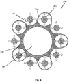
- the method 100 further includes the step ( FIG. 4 ) of positioning the bladders 201 and ply 210 to correspond to curved indentations 111 of the sprocket structure 110 and inflating the bladders 201 to tension and appropriately position the ply 210.
- the method 100 further includes the step ( FIG. 5 ) of providing or extruding a cylindrical ring structure 220, preferably a single piece cylindrical ring structure 220, made preferably out of a uniform, homogenous polymer, and sliding the structure 220 over the drum 101, sprocket structure 110, bladders 201, and ply 210.
- cylindrical ring structure 220 may be formed of a plurality of wedge profiles 251 ( FIG. 7 ) secured to each other to create the ring structure 220 of FIG. 5 .
- the method 100 preferably further includes the step ( FIG. 5 ) of positioning the bladders 201 and the ply 210 to correspond to curved indentations 211 of the ring structure 220 to form cylindrical cavities 111, 211 by the inflated bladders 201.
- the method 100 preferably further includes the step ( FIG. 6 ) of positioning and securing a layer 230 about the outer surface of the ring structure 220.
- the layer 230 may include a shear band structure and/or a tread structure.
- the drum 101 and bladders 201 then be deflated/contracted and axially removed from the entire structure, which now includes the sprocket structure 110, the ply 210, the ring structure 220, and the layer 230.
- the entire structure may then be cured and made ready to mount onto a rim vehicle.
Abstract
A method of manufacturing a wheel and tire assembly for a mobile vehicle which comprises the steps of: providing a cylindrical sprocket structure (110) out of a first polymer; sliding the sprocket structure (110) over a cylindrical tire building drum (101); forming an annular reinforcement layer by wrapping a ply (210) around a plurality of inflatable bladders (201); transferring the reinforcement layer and the bladders (201) to the sprocket structure (110); positioning the reinforcement layer and bladders (201) to correspond to curved indentations (111) of the sprocket structure (110); inflating the bladders (201) to tension and appropriately position the ply (210); providing a cylindrical ring structure (220) out of a second polymer; sliding the ring structure (220) over the drum (101); curing the sprocket structure (110) and the ring structure (220); deflating the bladders (201); contracting the drum (101); and mounting a complete cured structure comprising the cured sprocket structure (110) and the cured ring structure (220) on a vehicle wheel.
Description
- The present invention relates to wheel/tire assemblies, and more particularly, to a method of producing a wheel/tire assembly, preferably a non-pneumatic wheel/tire assembly.
- Radial pneumatic tires rely on the ply reinforcement to carry and transfer the load between the rim and the belt layer. These ply cords need to be tensioned to carry the load. Tensioning of these ply cords is achieved with the pressurized air in the inner chamber of the tire. If air pressure is lost, load carrying capacity of a pneumatic tire decreases significantly. Preventing the slow or sudden air pressure loss has been a challenge for the tire makers. One proposed solution is to use non-pneumatic tires. A top loader non-pneumatic tire can perform similar to a pneumatic tire if its durability, speed rating/limit and load capacity can be increased to the levels of a pneumatic tire.
- Many top loader non-pneumatic tires rely on the polymeric spokes to carry the load of the vehicle. Spokes transfer the load from the rim to the shear band. Due to the characteristics of the polymeric materials used in the spokes of these tires, performance of these tires is limited. It is an object of the present invention to overcome this limitation and increase the load carrying capacity and durability of these spokes and hence the performance of the top loader non-pneumatic tire.
- The invention relates to a method in accordance with claim 1.
- Dependent claims refer to preferred embodiments of the invention.
- A first method in accordance with a preferred aspect of the present invention manufactures a wheel and tire assembly for a mobile vehicle. The first preferred method includes the steps of: extruding a cylindrical sprocket structure out of a first polymer; sliding the structure over a cylindrical tire building drum; forming an annular reinforcement layer by wrapping a ply around inflatable bladders; transferring the reinforcement layer and bladders to a sprocket structure; positioning the bladders and ply to correspond to curved indentations of the sprocket structure; inflating the bladders to tension and appropriately position the ply; extruding a cylindrical ring structure out of a second polymer; sliding the ring structure over the tire building drum; positioning the bladders and ply to correspond to curved indentations of the ring structure; forming cylindrical cavities by the curved indentations of the sprocket structure and ring structure; securing an annular layer about an outer surface of the ring structure; deflating the bladders; contracting the tire building drum; removing the bladders and tire build drum from a complete structure including the sprocket structure, the ply, the ring structure, and the layer; curing the complete structure; and mounting the complete, cured structure on a vehicle wheel.
- According to another preferred aspect of the first method, the first polymer and the second polymer are the same material.
- According to still another preferred aspect of the first method, the first polymer is a homogenous rubber.
- According to yet another preferred aspect of the first method, the second polymer is a homogenous rubber.
- According to still another preferred aspect of the first method, the first polymer is uniform, homogenous rubber.
- According to yet another preferred aspect of the first method, the second polymer is a uniform, homogenous rubber.
- According to still another preferred aspect of the first method, another step constructs the sprocket structure from a plurality of wedge profiles.
- According to yet another preferred aspect of the first method, another step assembles the ring structure from a plurality of wedge profiles.
- According to still another preferred aspect of the first method, another step wraps the ply alternately inside a bladder and outside an adjacent bladder.
- According to yet another preferred aspect of the first method, another step of wraps the ply alternately outside a bladder and inside an adjacent bladder.
- A second preferred method in accordance with the present invention manufactures a wheel and tire assembly for a mobile vehicle. The second preferred method includes the steps of: extruding a cylindrical sprocket structure out of a first polymer; sliding the structure over a cylindrical tire building drum; forming an annular reinforcement layer by wrapping a ply alternately around an inside surface of an inflatable bladder and an outside surface an adjacent inflatable bladder; transferring the reinforcement layer and bladders to a sprocket structure; positioning the bladders and ply to correspond to curved indentations of the sprocket structure; inflating the bladders to tension and appropriately position the ply; extruding a cylindrical ring structure out of a second polymer; sliding the ring structure over the tire building drum; positioning the bladders and ply to correspond to curved indentations of the ring structure; forming cylindrical cavities by the curved indentations of the sprocket structure and ring structure; securing an annular layer about an outer surface of the ring structure; deflating the bladders; contracting the tire building drum; removing the bladders and tire build drum from a complete structure including the sprocket structure, the ply, the ring structure, and the layer; curing the complete structure; and mounting the complete, cured structure on a vehicle wheel.
- A third method in accordance with the present invention manufactures a wheel and tire assembly for a mobile vehicle. The method includes the steps of: providing or extruding a single piece cylindrical structure out of a polymer; removing polymer from the cylindrical structure to create a plurality of cylindrical cavities in the structure disposed concentrically about an axis of rotation of the cylindrical structure; mounting the cylindrical structure on to a central hub; and mounting an annular flexible rim on to the cylindrical structure.
- According to a preferred aspect of the third method, the providing or extruding step and the removing step occur simultaneously.
- According to another preferred aspect of the third method, the polymer has a uniform and/or homogenous structure.
- According to still another preferred aspect of the third method, each cylindrical cavity of the plurality of cylindrical cavities has a common diameter.
- According to yet another preferred aspect of the third method, each cylindrical cavity of the plurality of cylindrical cavities has a common length equal to a uniform axial thickness of the cylindrical structure.
- A system manufactures a wheel and tire assembly for a mobile vehicle. The system includes a single piece cylindrical structure extruded from a polymer, a plurality of cylindrical cavities in the cylindrical structure disposed concentrically about an axis of rotation of the cylindrical structure, the cylindrical cavities being formed by removing polymer from the cylindrical structure, a central hub secured to a radially inner surface of the cylindrical structure, and an annular flexible rim secured to a radially outer surface of the cylindrical structure.
- According to a preferred aspect of the system, the one piece cylindrical structure and cylindrical cavities are formed simultaneously.
- According to another preferred aspect of the system, the polymer has a uniform and/or homogenous structure.
- According to still another preferred aspect of the system, each cylindrical cavity of the plurality of cylindrical cavities has a common diameter.
- According to yet another preferred aspect of the system, each cylindrical cavity of the plurality of cylindrical cavities has a common length equal to a uniform axial thickness of the cylindrical structure.
- The present invention will be more clearly understood by the following description of some examples thereof, with reference to the accompanying drawings, in which:
-
FIG. 1 is a schematic view of part of an example manufacturing method in accordance with the present invention; -
FIG. 2 is a schematic view of another part of an example manufacturing method in accordance with the present invention; -
FIG. 3 is a schematic view of still another part of an example manufacturing method in accordance with the present invention; -
FIG. 4 is a schematic view of yet another part of an example manufacturing method in accordance with the present invention; -
FIG. 5 is a schematic view of still another part of an example manufacturing method in accordance with the present invention; -
FIG. 6 is a schematic view of yet another part of an example manufacturing method in accordance with the present invention; -
FIG. 7 is a schematic view of an example part for use with the example manufacturing method of the present invention; and -
FIG. 8 is a schematic view of another example part for use with the example manufacturing method of the present invention. - A conventional wheel, such as that described in
US-A-2004/0069385 , may have an outer rim flexibly connected to a central hub by means of lightweight composite springs. The springs may be plates fixed to the rim and to the hub. The hub may contain a speed reduction gear unit and/or an electric motor and may have a suspension mechanism for connecting a vehicle chassis to each wheel. The rim may be constructed from a flexible composite material, such as carbon fiber reinforced nylon material and have twin rubber tires and a plurality of circumferentially spaced-apart radial cleats which engage the ground and provide improved traction. The hub may also be formed from a carbon fiber reinforced composite material. - Another conventional wheel may have a rubber strip with a molded tread bonded to a composite rim for improved grip. Further, the springs interconnecting the rim and hub may be S-shaped lightweight composite springs.
- Still another conventional wheel may have a rim connected to a hub by means of a plurality of S-shaped springs. Each spring may have an inner end attached to the hub and an outer end attached to the rim. A different construction of rubber strip with molded tread may extend about an exterior of the rim.
- Yet another conventional wheel/tire assembly may be formed from a lightweight composite material, such as carbon fiber reinforced polyamide. The assembly may have a cylindrical central hub and a circular outer flexible rim mounted on the central hub by an endless looped spring band extending between the central hub and the circular rim. Six radial loops may be defined by the spring band. The spring band may be attached to the central hub and to the circular rim by any suitable means, such as adhesion, cohesion, soldering and/or mechanical fixing by means of bolts, rivets, and/or clamps. The assembly may further have a limit stop disc mounted on the central hub, coaxial with the central hub, and disposed radially outward from the central hub. An outer peripheral edge of the stop disc may be disposed spaced-apart and radially inward from an inner face of the circular rim for engagement with the circular rim upon radially inward flexing of the circular rim by a preset distance.
- Another example wheel/tire assembly may be formed from a lightweight polymer material, such as, for example, a standard tire rubber compound or other polymer. The assembly may have a cylindrical central hub, such as an automobile wheel, and a circular outer flexible rim, which may include a shear band and tread structure, mounted on the central hub by a toroidal, or doughnut-shaped, configuration or structure comprising the rubber compound extending between the central hub and the flexible rim.
- The toroidal configuration may further include cylindrical cavities disposed concentrically about the central hub allowing the configuration to deflect under load thereby defining a suitable balance between flexibility for ride comfort and traction within a footprint of the assembly and stiffness for vehicle handling, low rolling resistance, and low heat build-up of the configuration. The cylindrical cavities may further reduce assembly weight while the cylindrical shape of the cavities may maintain essentially homogenous and uniform pressure distribution within the rubber compound. The dimensions and number of the cylindrical cavities may be varied or made uniform for further tuning of the flexibility/stiffness of the assembly.
- Still another example wheel/tire assembly may be formed from a lightweight polymer material, such as, for example, a standard tire rubber compound or other polymer. The assembly may have a cylindrical central hub and a circular outer flexible rim mounted on the central hub by a toroidal configuration or structure comprising the rubber compound extending between the central hub and the circular rim.
- The toroidal configuration may further include cylindrical cavities disposed concentrically about the central hub allowing the configuration to deflect under load thereby defining a suitable balance between flexibility for ride comfort and traction within a footprint of the assembly and stiffness for vehicle handling, low rolling resistance, and low heat build-up of the configuration. The cylindrical cavities may further reduce assembly weight while the cylindrical shape of the cavities may maintain essentially homogenous and uniform pressure distribution within the rubber compound. The dimensions and number of the cylindrical cavities may be varied or made uniform for further tuning of the flexibility/stiffness of the assembly.
- Yet another example wheel/tire assembly may be formed of a polymer material, such as, for example, a standard tire rubber compound or other polymer. The assembly may have a cylindrical central hub and a circular outer flexible rim mounted on the central hub by a toroidal configuration or structure comprising the rubber compound extending between the central hub and the circular rim.
- The assembly may further include one or two reinforcing membranes interlaced circumferentially and radially about the cylindrical cavities for further tuning the flexibility/stiffness of the assembly. The membrane may be constructed of a metal, polymer, composite, and/or other suitable material for further refining the operating parameters of the assembly. The dimensions and number of layers of the membrane may be varied or made uniform for further tuning of the flexibility/stiffness of the assembly. The assembly may further include radially extending flexible shafts for further tuning the flexibility/stiffness of the assembly. The shafts may be constructed of a metal, polymer, composite, and/or other suitable material and may be designed to buckle at a predetermined load for further refining the operating parameters of the assembly.
- A
method 100 of manufacturing a wheel and tire assembly for a mobile vehicle (FIGS. 1-6 ) in accordance with the present invention includes providing or extruding acylindrical sprocket structure 110, preferably a single piececylindrical sprocket structure 110, made preferably out of a uniform, homogenous polymer, and sliding the structure over a cylindricaltire building drum 101. - Alternatively, the
cylindrical structure 110 may be formed of a plurality of wedge profiles 151 (FIG. 8 ) secured to each other to create thesprocket structure 110 ofFIG. 1 . - The
method 100 further includes the step (FIG. 2 ) of forming a reinforcement layer by wrapping aply 210 aroundinflatable rubber bladders 201 and transferring the reinforcement layer and the bladders to the sprocket structure 110 (FIG. 3 ). Themethod 100 further includes the step (FIG. 4 ) of positioning thebladders 201 and ply 210 to correspond tocurved indentations 111 of thesprocket structure 110 and inflating thebladders 201 to tension and appropriately position theply 210. - The
method 100 further includes the step (FIG. 5 ) of providing or extruding acylindrical ring structure 220, preferably a single piececylindrical ring structure 220, made preferably out of a uniform, homogenous polymer, and sliding thestructure 220 over thedrum 101,sprocket structure 110,bladders 201, and ply 210. - Alternatively, the
cylindrical ring structure 220 may be formed of a plurality of wedge profiles 251 (FIG. 7 ) secured to each other to create thering structure 220 ofFIG. 5 . - The
method 100 preferably further includes the step (FIG. 5 ) of positioning thebladders 201 and theply 210 to correspond tocurved indentations 211 of thering structure 220 to formcylindrical cavities inflated bladders 201. - The
method 100 preferably further includes the step (FIG. 6 ) of positioning and securing alayer 230 about the outer surface of thering structure 220. - The
layer 230 may include a shear band structure and/or a tread structure. - The
drum 101 andbladders 201 then be deflated/contracted and axially removed from the entire structure, which now includes thesprocket structure 110, theply 210, thering structure 220, and thelayer 230. - The entire structure may then be cured and made ready to mount onto a rim vehicle.
Claims (12)
- A method of manufacturing a wheel and tire assembly for a mobile vehicle, the method comprising the steps of:providing or extruding a cylindrical sprocket structure (110) out of a first polymer;sliding the sprocket structure (110) over a cylindrical tire building drum (101);forming an annular reinforcement layer by wrapping a ply (210) around a plurality of inflatable bladders (201);transferring the reinforcement layer and the bladders (201) to the sprocket structure (110);positioning the reinforcement layer and bladders (201) to correspond to curved indentations (111) of the sprocket structure (110);inflating the bladders (201) to tension and appropriately position the ply (210);providing or extruding a cylindrical ring structure (220) out of a second polymer;sliding the ring structure (220) over the tire building drum (101);curing the sprocket structure (110) and the ring structure (220);deflating the bladders (201);contracting the tire building drum (101); andmounting a complete cured structure comprising the cured sprocket structure (110) and the cured ring structure (220) on a vehicle wheel.
- The method of claim 1, further comprising:positioning the bladders (201) and the reinforcement layer to correspond to curved indentations of the ring structure (220);forming cylindrical cavities (211) by the curved indentations (111) of the sprocket structure (110) and of the ring structure (220).
- The method of claim 1 or 2, further comprising:securing an annular layer (230) or tread about an outer surface of the ring structure (220).
- The method as set forth in at least one of the previous claims wherein the first polymer and the second polymer are the same material.
- The method as set forth in at least one of the previous claims wherein the first polymer and/or the second polymer is a homogenous rubber or a uniform homogenous rubber.
- The method as set forth in at least one of the previous claims further including the step of constructing the sprocket structure (110) from a plurality of wedge profiles (151).
- The method as set forth in at least one of the previous claims further including the step of assembling the ring structure (220) from a plurality of wedge profiles (251).
- The method as set forth in at least one of the previous claims further including the step of wrapping the ply (210) alternately inside a bladder and outside an adjacent bladder or alternately outside a bladder and inside an adjacent bladder.
- The method as set forth in at least one of the previous claims further including the step of forming the annular reinforcement layer by wrapping the ply (210) alternately around an inside surface of an inflatable bladder and an outside surface an adjacent inflatable bladder.
- The method as set forth in at least one of the previous claims further including the steps of:removing the bladders (201) and the tire building drum (101) from a completed structure including the sprocket structure (110), the ply (210), the ring structure (220) and preferably also the layer (230); andcuring the completed structure.
- The method as set forth in at least one of the previous claims wherein the step of curing the sprocket structure (110) and the ring structure (220) is after the step of deflating the bladders (201) and after the step of contracting the tire building drum (101).
- The method as set forth in at least one of the previous claims wherein the step of curing the completed structure is after the step of removing the bladders (201) and the tire building drum (101) from the completed structure.
Applications Claiming Priority (1)
| Application Number | Priority Date | Filing Date | Title |
|---|---|---|---|
| US15/351,727 US10259179B2 (en) | 2016-11-15 | 2016-11-15 | Method of producing a non-pneumatic support structure |
Publications (1)
| Publication Number | Publication Date |
|---|---|
| EP3321076A1 true EP3321076A1 (en) | 2018-05-16 |
Family
ID=60262781
Family Applications (1)
| Application Number | Title | Priority Date | Filing Date |
|---|---|---|---|
| EP17199945.1A Withdrawn EP3321076A1 (en) | 2016-11-15 | 2017-11-03 | Method of producing a wheel and tire assembly |
Country Status (6)
| Country | Link |
|---|---|
| US (1) | US10259179B2 (en) |
| EP (1) | EP3321076A1 (en) |
| JP (1) | JP6964488B2 (en) |
| KR (1) | KR101955822B1 (en) |
| CN (1) | CN108068372B (en) |
| BR (1) | BR102017024128A2 (en) |
Families Citing this family (3)
| Publication number | Priority date | Publication date | Assignee | Title |
|---|---|---|---|---|
| US10286725B2 (en) | 2017-03-22 | 2019-05-14 | The Goodyear Tire & Rubber Company | Non-pneumatic support structure |
| EP3871902B1 (en) | 2020-02-28 | 2023-07-19 | The Goodyear Tire & Rubber Company | Non-pneumatic tire |
| CN114131976B (en) * | 2022-02-08 | 2022-05-27 | 天津赛象科技股份有限公司 | Belt and drum forming integrated chassis of tire forming machine and working method of integrated chassis |
Citations (8)
| Publication number | Priority date | Publication date | Assignee | Title |
|---|---|---|---|---|
| SU619352A1 (en) * | 1976-05-24 | 1978-08-15 | Всесоюзный Научно-Исследовательский И Конструкторский Институт По Оборудованию Для Шинной Промышленности | Framework-transporting device |
| US20040069385A1 (en) | 2002-07-01 | 2004-04-15 | Sean Timoney | Wheel |
| EP1902866A1 (en) * | 2006-09-25 | 2008-03-26 | Bridgestone Corporation | Non-pneumatic tire |
| WO2011025491A1 (en) * | 2009-08-28 | 2011-03-03 | Michelin Recherche Et Technique, S.A. | A non-pneumatic wheel assembly with removable hub |
| EP2527132A1 (en) * | 2010-01-18 | 2012-11-28 | Kabushiki Kaisha Bridgestone | Tire manufacturing device |
| US20140083581A1 (en) * | 2012-09-27 | 2014-03-27 | Mtd Products Inc. | Non-pneumatic tire |
| EP2727713A1 (en) * | 2012-10-31 | 2014-05-07 | The Goodyear Tire & Rubber Company | Method and apparatus for applying an annular strip to a tire |
| WO2016178970A1 (en) * | 2015-05-01 | 2016-11-10 | Compagnie Generale Des Etablissements Michelin | Method of curing a polymeric form and curing device for polymeric materials using thermal expansion |
Family Cites Families (29)
| Publication number | Priority date | Publication date | Assignee | Title |
|---|---|---|---|---|
| US479255A (en) | 1892-07-19 | boyd dunlop | ||
| US482175A (en) | 1892-09-06 | George hollafolla | ||
| US1002003A (en) | 1910-07-23 | 1911-08-29 | Christian J Simonson | Steel tire. |
| US1233722A (en) | 1917-01-03 | 1917-07-17 | Frederick Kemppel | Resilient wheel. |
| US1389285A (en) | 1920-03-29 | 1921-08-30 | August W Althoff | Vehicle-wheel |
| US1451517A (en) | 1922-02-27 | 1923-04-10 | William H Smith | Spring wheel |
| US1930764A (en) | 1931-11-05 | 1933-10-17 | Wingfoot Corp | Pneumatic tire and method of making same |
| US3493027A (en) | 1966-05-20 | 1970-02-03 | Nasa | Deformable vehicle wheel |
| US3801028A (en) * | 1971-10-20 | 1974-04-02 | Advance Mfg Co | Machine for making twisted wire beads for tires |
| US3909335A (en) * | 1974-05-22 | 1975-09-30 | Gen Tire & Rubber Co | Pneumatic tire transporter |
| US4235270A (en) | 1978-06-30 | 1980-11-25 | The Goodyear Tire & Rubber Company | Tire with supporting and cushioning walls |
| US4226273A (en) | 1978-06-30 | 1980-10-07 | The Goodyear Tire & Rubber Company | Nonpneumatic tire and rim assembly |
| US4602823A (en) | 1981-08-18 | 1986-07-29 | Berg Charles A | Portable collapsible wheels |
| CA2043082A1 (en) | 1991-02-27 | 1992-08-28 | James Edward Duddey | Non-pneumatic spare tire |
| KR940010619B1 (en) * | 1992-02-12 | 1994-10-24 | 주식회사 금호 | Non-pneumatic tire |
| US5800643A (en) | 1996-04-26 | 1998-09-01 | Inner Tire Corporation | Pneumatic inner tire |
| EP0890453B1 (en) | 1997-07-11 | 2004-09-29 | Sumitomo Rubber Industries Limited | Pneumatic tyre |
| US6068721A (en) | 1998-03-27 | 2000-05-30 | The Goodyear Tire & Rubber Company | Method of fabricating a tire having a geodesic ply |
| JP4093318B2 (en) * | 2006-03-10 | 2008-06-04 | 横浜ゴム株式会社 | Non-pneumatic tire and manufacturing method thereof |
| JP2008132951A (en) * | 2006-11-29 | 2008-06-12 | Yokohama Rubber Co Ltd:The | Non-pneumatic tire |
| EP2170625A4 (en) | 2007-06-29 | 2012-05-30 | Michelin Soc Tech | Elastic shear band with cylindrical elements |
| FR2928865B1 (en) | 2008-03-19 | 2010-03-19 | Michelin Soc Tech | NON-PNEUMATIC ELASTIC WHEEL |
| JP5033070B2 (en) * | 2008-06-23 | 2012-09-26 | 東洋ゴム工業株式会社 | Non-pneumatic tire manufacturing method |
| CN101439645A (en) * | 2008-12-19 | 2009-05-27 | 邢庆云 | Composite bed non-inflatable tyre produced from waste and old tyres and method for producing the same |
| CN103260909B (en) * | 2010-12-28 | 2015-08-05 | 瓦斯菲·阿希达法特 | Half pneumatic type tire (inner tube of a tyre) |
| KR101559315B1 (en) * | 2010-12-29 | 2015-10-12 | 미쉐린 러쉐르슈 에 떼크니크 에스.에이. | Structurally supported non-pneumatic wheel with reinforcements and method of manufacture |
| AP2014008181A0 (en) * | 2011-05-24 | 2014-12-31 | Prospect Sa Invest 121 Ltd | An airless tyre for vehicles |
| US8720504B2 (en) * | 2011-06-17 | 2014-05-13 | The Goodyear Tire & Rubber Company | System for non-pneumatic support of a vehicle |
| CN205417037U (en) * | 2016-04-11 | 2016-08-03 | 山东玲珑轮胎股份有限公司 | Non-pneumatic tire |
-
2016
- 2016-11-15 US US15/351,727 patent/US10259179B2/en active Active
-
2017
- 2017-11-03 EP EP17199945.1A patent/EP3321076A1/en not_active Withdrawn
- 2017-11-09 BR BR102017024128-9A patent/BR102017024128A2/en not_active IP Right Cessation
- 2017-11-13 KR KR1020170150736A patent/KR101955822B1/en active IP Right Grant
- 2017-11-15 JP JP2017219941A patent/JP6964488B2/en active Active
- 2017-11-15 CN CN201711129513.2A patent/CN108068372B/en active Active
Patent Citations (8)
| Publication number | Priority date | Publication date | Assignee | Title |
|---|---|---|---|---|
| SU619352A1 (en) * | 1976-05-24 | 1978-08-15 | Всесоюзный Научно-Исследовательский И Конструкторский Институт По Оборудованию Для Шинной Промышленности | Framework-transporting device |
| US20040069385A1 (en) | 2002-07-01 | 2004-04-15 | Sean Timoney | Wheel |
| EP1902866A1 (en) * | 2006-09-25 | 2008-03-26 | Bridgestone Corporation | Non-pneumatic tire |
| WO2011025491A1 (en) * | 2009-08-28 | 2011-03-03 | Michelin Recherche Et Technique, S.A. | A non-pneumatic wheel assembly with removable hub |
| EP2527132A1 (en) * | 2010-01-18 | 2012-11-28 | Kabushiki Kaisha Bridgestone | Tire manufacturing device |
| US20140083581A1 (en) * | 2012-09-27 | 2014-03-27 | Mtd Products Inc. | Non-pneumatic tire |
| EP2727713A1 (en) * | 2012-10-31 | 2014-05-07 | The Goodyear Tire & Rubber Company | Method and apparatus for applying an annular strip to a tire |
| WO2016178970A1 (en) * | 2015-05-01 | 2016-11-10 | Compagnie Generale Des Etablissements Michelin | Method of curing a polymeric form and curing device for polymeric materials using thermal expansion |
Also Published As
| Publication number | Publication date |
|---|---|
| BR102017024128A2 (en) | 2018-06-12 |
| KR101955822B1 (en) | 2019-03-07 |
| CN108068372A (en) | 2018-05-25 |
| JP2018079693A (en) | 2018-05-24 |
| US20180133993A1 (en) | 2018-05-17 |
| KR20180054486A (en) | 2018-05-24 |
| JP6964488B2 (en) | 2021-11-10 |
| CN108068372B (en) | 2019-09-27 |
| US10259179B2 (en) | 2019-04-16 |
Similar Documents
| Publication | Publication Date | Title |
|---|---|---|
| CN108068549B (en) | Non-inflatable support structure | |
| US10150334B2 (en) | Non-pneumatic support structure | |
| US10406852B2 (en) | Non-pneumatic support structure | |
| US11020918B2 (en) | Method of manufacturing a non-pneumatic support structure | |
| EP3330098A1 (en) | Wheel assembly for a support structure and system for supporting a load | |
| US10457094B2 (en) | Wheel for a support structure | |
| US10471773B2 (en) | Method of manufacturing a non-pneumatic support structure | |
| EP3321076A1 (en) | Method of producing a wheel and tire assembly | |
| EP4008539A2 (en) | System and method for manufacturing a support structure | |
| EP3822092B1 (en) | Wheel assembly for a support structure | |
| US11806960B2 (en) | System for manufacturing a support structure | |
| US11801651B2 (en) | System for manufacturing a support structure | |
| EP3812168A1 (en) | Modular non-pneumatic support structure and method | |
| US20230060519A1 (en) | System for manufacturing a support structure | |
| US20230144443A1 (en) | Wheel for a support structure |
Legal Events
| Date | Code | Title | Description |
|---|---|---|---|
| PUAI | Public reference made under article 153(3) epc to a published international application that has entered the european phase |
Free format text: ORIGINAL CODE: 0009012 |
|
| AK | Designated contracting states |
Kind code of ref document: A1 Designated state(s): AL AT BE BG CH CY CZ DE DK EE ES FI FR GB GR HR HU IE IS IT LI LT LU LV MC MK MT NL NO PL PT RO RS SE SI SK SM TR |
|
| AX | Request for extension of the european patent |
Extension state: BA ME |
|
| STAA | Information on the status of an ep patent application or granted ep patent |
Free format text: STATUS: THE APPLICATION IS DEEMED TO BE WITHDRAWN |
|
| 18D | Application deemed to be withdrawn |
Effective date: 20181117 |