EP3321060A1 - Dispositif de buse de moulage par injection - Google Patents
Dispositif de buse de moulage par injection Download PDFInfo
- Publication number
- EP3321060A1 EP3321060A1 EP17201485.4A EP17201485A EP3321060A1 EP 3321060 A1 EP3321060 A1 EP 3321060A1 EP 17201485 A EP17201485 A EP 17201485A EP 3321060 A1 EP3321060 A1 EP 3321060A1
- Authority
- EP
- European Patent Office
- Prior art keywords
- spacer
- injection molding
- material tube
- mounting plate
- guide sleeve
- Prior art date
- Legal status (The legal status is an assumption and is not a legal conclusion. Google has not performed a legal analysis and makes no representation as to the accuracy of the status listed.)
- Granted
Links
- 238000001746 injection moulding Methods 0.000 title claims abstract description 40
- 239000000463 material Substances 0.000 claims abstract description 115
- 125000006850 spacer group Chemical group 0.000 claims abstract description 69
- 238000010438 heat treatment Methods 0.000 claims abstract description 28
- 230000009969 flowable effect Effects 0.000 claims abstract description 15
- 230000008878 coupling Effects 0.000 claims description 30
- 238000010168 coupling process Methods 0.000 claims description 30
- 238000005859 coupling reaction Methods 0.000 claims description 30
- 238000002347 injection Methods 0.000 claims description 10
- 239000007924 injection Substances 0.000 claims description 10
- 230000002093 peripheral effect Effects 0.000 claims description 4
- RTAQQCXQSZGOHL-UHFFFAOYSA-N Titanium Chemical compound [Ti] RTAQQCXQSZGOHL-UHFFFAOYSA-N 0.000 description 3
- 229910052751 metal Inorganic materials 0.000 description 3
- 239000002184 metal Substances 0.000 description 3
- 239000010936 titanium Substances 0.000 description 3
- 229910052719 titanium Inorganic materials 0.000 description 3
- 238000004891 communication Methods 0.000 description 2
- 238000013461 design Methods 0.000 description 2
- 238000009434 installation Methods 0.000 description 2
- 238000012546 transfer Methods 0.000 description 2
- 239000000919 ceramic Substances 0.000 description 1
- 238000010276 construction Methods 0.000 description 1
- 239000012530 fluid Substances 0.000 description 1
- 238000009413 insulation Methods 0.000 description 1
- 238000012423 maintenance Methods 0.000 description 1
- 238000000034 method Methods 0.000 description 1
- 238000000465 moulding Methods 0.000 description 1
Images


Classifications
-
- B—PERFORMING OPERATIONS; TRANSPORTING
- B29—WORKING OF PLASTICS; WORKING OF SUBSTANCES IN A PLASTIC STATE IN GENERAL
- B29C—SHAPING OR JOINING OF PLASTICS; SHAPING OF MATERIAL IN A PLASTIC STATE, NOT OTHERWISE PROVIDED FOR; AFTER-TREATMENT OF THE SHAPED PRODUCTS, e.g. REPAIRING
- B29C45/00—Injection moulding, i.e. forcing the required volume of moulding material through a nozzle into a closed mould; Apparatus therefor
- B29C45/17—Component parts, details or accessories; Auxiliary operations
- B29C45/26—Moulds
- B29C45/27—Sprue channels ; Runner channels or runner nozzles
- B29C2045/2759—Nozzle centering or guiding means
-
- B—PERFORMING OPERATIONS; TRANSPORTING
- B29—WORKING OF PLASTICS; WORKING OF SUBSTANCES IN A PLASTIC STATE IN GENERAL
- B29C—SHAPING OR JOINING OF PLASTICS; SHAPING OF MATERIAL IN A PLASTIC STATE, NOT OTHERWISE PROVIDED FOR; AFTER-TREATMENT OF THE SHAPED PRODUCTS, e.g. REPAIRING
- B29C45/00—Injection moulding, i.e. forcing the required volume of moulding material through a nozzle into a closed mould; Apparatus therefor
- B29C45/17—Component parts, details or accessories; Auxiliary operations
- B29C45/26—Moulds
- B29C45/27—Sprue channels ; Runner channels or runner nozzles
- B29C2045/2764—Limited contact between nozzle and mould
-
- B—PERFORMING OPERATIONS; TRANSPORTING
- B29—WORKING OF PLASTICS; WORKING OF SUBSTANCES IN A PLASTIC STATE IN GENERAL
- B29C—SHAPING OR JOINING OF PLASTICS; SHAPING OF MATERIAL IN A PLASTIC STATE, NOT OTHERWISE PROVIDED FOR; AFTER-TREATMENT OF THE SHAPED PRODUCTS, e.g. REPAIRING
- B29C45/00—Injection moulding, i.e. forcing the required volume of moulding material through a nozzle into a closed mould; Apparatus therefor
- B29C45/17—Component parts, details or accessories; Auxiliary operations
- B29C45/26—Moulds
- B29C45/27—Sprue channels ; Runner channels or runner nozzles
- B29C2045/2766—Heat insulation between nozzle and mould
Definitions
- the invention relates to an injection molding device according to claim 1.
- Injection molding dies are used in injection molds in order to supply a flowable mass to a separable tool block (mold cavity) at a predeterminable temperature under high pressure. They usually have a nozzle body in the form of a material tube, in which a flow channel for the flowable mass is formed. This ends in a nozzle mouthpiece, which is inserted into the end of the material tube and forms the outlet opening for the flow channel.
- an electric heater is provided, which concentrically surrounds the material pipe or the flow channel formed therein. This makes it possible to keep the flowable mass into the nozzle tip at a constant temperature.
- a thermal break between the The hot housing and the mostly cooled tool ensures that the nozzle does not freeze - especially in the area of the nozzle tip - and at the same time the tool (mold cavity) is not heated.
- a temperature sensor is usually used.
- Material pipe and heating can be designed as separate components, the heater is integrated together with the temperature sensor in a sheath, which is pushed circumferentially on the material pipe. But you can also integrate the heater in the material pipe, for example, as a tubular heater or as a coil, or you bring the cohesive material as a layer heating on the material pipe.
- the material pipe usually sits in a housing which is in communication with a distributor plate in the injection mold in such a way that the flow channel in the material tube is in flow communication with the flow channels in the distributor plate. Between the material pipe and the housing, an air gap for thermal insulation is formed. For a stable bearing, the housing is supported on the front and rear end of the material pipe. The air volume in the air gap is sealed as far as possible. The disadvantage here are thermal bridges at the contact points to the material pipe. The housing in turn is supported on the distributor plate and / or the mold plate, which enhances the heat flow from the material tube to the housing. This not only leads to an increased energy requirement for the heating, but also to a thermal unequal distribution over the length of the material tube.
- the present invention is based on the object to provide an improved injection molding device, which allows a uniform temperature profile over the length of a material pipe
- the invention relates to an injection molding nozzle device with at least one material tube, wherein the at least one material tube extends in a longitudinal direction.
- a flow channel for a flowable mass is further formed, wherein the at least one material tube at a front end of the flow channel has a nozzle tip with at least one outlet opening for the flowable mass.
- the at least one material tube At a rear End of the flow channel, the at least one material tube at least one inlet opening for the flowable mass and is fixed to a mounting plate.
- the at least one material tube is heated with a heating device and arranged in a housing, wherein it is arranged without contact inside the housing in a longitudinally aligned section with the exception of the heating device on the outer circumference.
- the section is arranged adjacent to the mounting plate and extends in the direction of the front end.
- the housing has a one-piece spacer and each material tube a guide sleeve, each guide sleeve is attached to the spacer and wherein the spacer is fixed to the mounting plate and defines the distance between the guide sleeve and mounting plate.
- the advantage of this is that the material pipe no thermal bridges are formed by other components in the vicinity of the mounting plate, since the housing is not supported on the material pipe. Accordingly, little heat flows from the material pipe here. The energy required to operate the heater is thereby lower and it is achieved a more uniform temperature distribution over the length of the material tube. Furthermore, a simple holder and positioning of the guide sleeves for the material pipes is possible by a one-piece spacer.
- the spacer is designed according to one embodiment as a peripheral frame which radially surrounds the at least one material tube and is spaced from the at least one material tube.
- the frame may consist, for example, of metal or a ceramic.
- the frame can have any geometry.
- limits for the design options arise from the requirement that the spacer must withstand the forces based on the injection pressures of up to 2000 bar, which is why corresponding machine nozzle contact forces are present in order to keep the mold closed.
- the frame has at least one recess through which at least one material tube is accessible from outside the frame.
- the at least one recess is a wiring and power supply of the heater, as well as the reading of existing within the frame temperature sensors possible.
- the recesses are preferably designed so that through the recesses existing contacts of the heater are easily accessible. Furthermore, the recesses are preferably dimensioned so that they affect the stability of the frame as little as possible.
- the at least one guide sleeve has a coupling means.
- the coupling means can be designed for a non-positive and / or positive connection with the spacer.
- the coupling means is preferably formed integrally with the guide sleeve to ensure sufficient stability.
- the coupling means may be a part of a bayonet closure which is designed to engage in a correspondingly opposite coupling means of the spacer.
- the coupling means is an external thread.
- the external thread is preferably arranged on a rear, the mounting plate facing the end of the guide sleeve.
- internal threads are provided in this case to the external threads, so that the at least one guide sleeve can be screwed into the spacer.
- a stop is preferably formed in the spacer, which limits the possible depth of engagement of a guide sleeve.
- the engagement depth of the guide sleeve is chosen exactly so that the guide sleeve does not protrude beyond the end face of the spacer with which the spacer rests on the mold plate. So a thermal bridge can be avoided at this point.
- an air gap of about 1 mm remains between the guide sleeve and the mold plate.
- the coupling means is a projection on an end of the at least one material tube facing the rear of the mounting plate, wherein the housing has an additional fixing element which can be fixed to the spacer such that the coupling means between the fixing element and the spacer is clamped.
- the fixing element may be a plateau arrangement in which recesses for receiving the at least one guide sleeve are formed.
- the fixing element For attachment of the at least one guide sleeve, it can first be passed through the recess until the guide sleeve rests with its projection on a surface of the fixing element. Subsequently, the fixing element is attached to the spacer, for example screwed, so that the projection between the fixing and spacer is clamped.
- a receiving geometry for the coupling means is formed in the spacer and / or the fixing element.
- the receiving geometry may be, for example, a recess which is adapted in its shape to the shape of the projection.
- a permanent connection can also be provided.
- guide sleeve and spacers for example, materially connected, for example, be welded.
- the spacer is attachable to the mounting plate.
- the spacer is indirectly or directly bolted to the mounting plate.
- eyelets can be arranged in or on the spacer into which a screw can engage, which in turn into the mounting plate is screwed in.
- the eyelets are preferably made in one piece with the spacer.
- An indirect screwing for example, be realized by the above-described fixing of the housing is screwed to the mounting plate, that by tightening the screws, the fixing element exerts a force on the spacer towards the mounting plate. As a result, the spacer between the mounting plate and the fixing can be clamped. It can be ensured by appropriate positioning and anti-rotation the correct orientation of the spacer.
- the heating device is arranged without contact in the section with the exception of the material pipes. Accordingly, heat from the heater in the section also does not leak heat to components other than the material pipe. Inadvertent heating of an opposing mold plate is also avoided.
- the length of the section in the longitudinal direction is at least half the total length of the material tube in the longitudinal direction.
- a coupling means for fixing the material pipe to the mounting plate is formed at the rear end on each of the material pipes.
- the coupling means is a thread, in particular an external thread, or a bayonet means. This allows a firm and tight connection.
- each of the material pipes peripherally supports an electric heater of the heater, and the heating elements are arranged without contact in the region of the portion except for the material pipe.
- These heating elements can be designed in particular sleeve or sleeve shape for uniform temperature.
- the heating elements preferably extend from the front end of the material tube to the stop or the mounting plate at the rear end.
- the heating device in each case has a heating cartridge. This sits either in the flow channel of the material pipes or else it is inserted in the longitudinal direction in the wall of the material pipes.
- the first variant is one Direct heating of the fluid mass in the flow channel and inside the material pipe possible.
- the second variant allows easy installation and interchangeability.
- At least one positioning element is formed on the spacer, which is designed for positioning the injection molding device in an injection mold.
- the positioning elements may be pins or bolts which project from the spacer and, in the mounted position of the injection molding nozzle device, engage in corresponding receptacles of a molding plate of an injection molding tool.
- such positioning elements can also be formed on the fixing element.
- the at least one guide sleeve is supported indirectly or directly exclusively at the front end of the at least one material tube.
- the at least one guide sleeve is divided into two, wherein a front end of the sleeve consists of a first material and wherein a rear end of the sleeve consists of a second material, wherein the front end of the sleeve is connected to the rear end of the sleeve.
- the front sleeve end may be connected to the rear sleeve end via a screw or bayonet connection.
- the connection of the sleeve ends can also be a cohesive connection.
- the first material of the front sleeve end is preferably made of a metal with little heat conductivity, so that heat transfer from the material tube to the guide sleeve is reduced.
- the front sleeve end is made of titanium.
- FIG. 1 an injection molding nozzle device 1 is shown in perspective view.
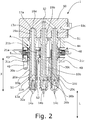
- Fig. 2 shows a longitudinal section through the injection molding device 1 after Fig. 1
- Fig. 3 one to the representation of Fig. 2 vertical longitudinal section through the injection molding device 1 shows.
- the Spritzg hassledüsenvorraum 1 has three identical material tubes 10 a, 10 b, 10 c, of which in the Fig. 1 and 2 three and in Fig. 3 only one is visible.
- Each of the material tubes 10a, 10b, 10c extends in a longitudinal direction L, ie the material tubes 10a, 10b, 10c are aligned parallel to each other.
- a flow channel 11a is formed for a flowable mass.
- each of the material pipes 10a, 10b, 10c has at a front end 12a of the flow channel 11a via a nozzle tip 14a, 14b, 14c with at least one flowable material outlet opening.
- the nozzle tips 14, 14 a, 14 b, 14 c are all identical and in the FIGS. 1 . 2 . 3 . 4a ) and 5a ) executed as open nozzle tips.
- the nozzle tips 14, 14 a, 14 b, 14 c are formed with a needle valve, as in the FIGS. 4b ) and 5b ) is shown.
- Each of the material tubes 10a, 10b, 10c has at least one inlet opening 16a for the flowable mass at a rear end 13a of the flow channel 11a and a stop 17a for defined positioning on a mounting plate 50.
- the mounting plate 50 may be, for example, the distributor of an injection mold act. Consequently, the mounting plate 50 be equipped with a heater 51, as exemplified in the FIGS. 1 . 2 and 3 is shown. The heater 51 is inserted into a corresponding groove in the mounting plate 51. As in Fig. 2 and 3 is shown, the mounting plate 50 has a central inlet opening, to which a distributor plate or a central machine nozzle can be connected.
- each of the material pipes 10a, 10b, 10c is heated with a heater 20a, 20b, 20c.
- each material tube 10a, 10b, 10c circumferentially carries a sleeve-shaped heating element, which is connected via terminals 21a, 21b, 21c to a power supply.
- the heating element 10a, 10b, 10c is preferably a carrier sleeve with thick film heating.
- any other heater can be used.
- a coupling means 19a for fixing the material pipe 10a, 10b, 10c to the mounting plate 50 is formed on each of the material pipes 10a, 10b, 10c. It is an external thread in the illustrated embodiment.
- a tool holder can be arranged on each of the material pipes 10a, 10b, 10c in order to screw the coupling means 19a into the mounting plate 50.
- FIGS. 4 a) and b) show a substantially the same structure of a Spritzg phonedüsenvorraum 1.
- the illustrated Spritzg cleverdüsenvorraum 1 each equipped with only a single material pipe 10.
- the show FIGS. 4 b) and 5 b) each injection molding nozzle devices 1 the material tubes 10 are equipped with a nozzle tip 14, which are designed to receive a closure needle.
- a guide 22 for a closure needle is further formed in the flow channel 11.
- Fig. 1 . 2 . 3 . 4 and 5 have in common that each of the material tubes 10, 10a, 10b, 10c in a longitudinally L aligned portion A with the exception of the heater 20, 20a, 20b, 20c is arranged without contact on the outer circumference, wherein the portion A is adjacent to the mounting plate 50 and extends in the direction of the front end 12, 12 a.
- the heating elements of the heating device 20, 20a, 20b, 20c are arranged in the section A with the exception of the material tubes 10, 10a, 10b, 10c without contact. Excepted from this, however, are the connecting lines 21 a, 21 b, 21 c, which lead to the heating elements.
- the length of the section A in the longitudinal direction L more than half the total length of the material tube 10, 10a, 10b, 10c in the longitudinal direction L.
- the section A extends in each case from the distributor 50 to the front end 12, 12a of the material tube 10, 10a, 10b, 10c.
- FIGS. 1 to 5 a housing having at least one integral spacer 44 to which the guide sleeves 30, 30a, 30b, 30c are attached.
- Each of the material tubes 10a, 10b, 10c is arranged with the front end 12a within a guide sleeve 30, 30a, 30b, 30c and protrudes with the rear end 13a and the stop 17a from a rear sleeve end 31, 31a, 31b, 31c of the guide sleeve 30, 30a, 30b, 30c out.
- an air gap S1, S2 is formed between the material pipe 10a, 10b, 10c and the guide sleeve 30, 30a, 30b, 30c.
- the material tube 10, 10 a, 10 b, 10 c at the rear end of the sleeve 31, 31 a, 31 b, 31 c contactless to the guide sleeve 30, 30 a, 30 b, 30 c.
- the guide sleeve 30, 30a, 30b, 30c in the direction of the rear sleeve end 31, 31a, 31b, 31c over at least two thirds of its total length X is contactless to the material tube 10, 10a, 10b, 10c.
- the guide sleeve 30, 30a, 30b, 30c is supported exclusively with a front sleeve end 32, 32a at the front end 12, 12a of the material tube 10, 10a, 10b, 10c on the material tube 10, 10a, 10b, 10c.
- the front sleeve end 32, 32a is made of titanium.
- the guide sleeves 30, 30a, 30b, 30c are identical parts.
- the rear sleeve end 31, 31 a, 31 b, 31 c of the guide sleeves 30, 30 a, 30 b, 30 c is arranged in the longitudinal direction L spaced from the mounting plate 50.
- the guide sleeves 30, 30a, 30b, 30c are each formed in two parts, wherein the front sleeve end 32, 32a of a first material and the rear sleeve end 31, 31a, 31b, 31c consists of a second material.
- the front sleeve end 32, 32a is connected in each case at a coupling point with the rear sleeve end 31, 31a, 31b, 31c.
- the first material consists of a less highly thermally conductive metal, in particular titanium, as the rear end of the sleeve 31, 31 a, 31 b, 31 c.
- FIGS. 1 to 5 Variants shown differ essentially by the structure of the housing in which the material tubes 10, 10a, 10b, 10c are arranged, or in the manner of storage of the guide sleeves 30, 30a, 30b, 30c.
- the spacer 44 is connected on a first side with a fixing element 40 in the form of a holding plate, while it is connected to the mounting plate 50 on a second side.
- a screw 47 is guided in the region of the corners of the fixing element 40 through the fixing element 40 and the spacer 44 and screwed into the mounting plate 50.
- any other detachable or permanent type of connection between fixing element 40 and spacer 44 on the one hand and spacers 44 and mounting plate 50 on the other hand can be used.
- the spacer 44 may be crimped, welded, riveted, pinned, or otherwise permanently or releasably connected to the fuser 40 and / or mounting plate 50.
- a detachable connection has the advantage that for the maintenance of the heating elements, the injection molding device 1 can be easily disassembled into their individual parts.
- the fixing member 40 is spaced from each of the material pipes 10a, 10b, 10c and the heater 20a, 20b, 20c.
- Each of the material tubes 10a, 10b, 10c projects through a respective recess in the fixing element 40.
- the fixing element 40 is aligned transversely to the longitudinal direction L.
- the spacer 44 is designed as a peripheral frame which encloses the material pipes 10a 10b 10c in the area between the mounting plate 50 and the fixing element 40 in the radial direction.
- In the frame side recesses 48 are formed, through which a contacting of the heating elements via the terminals 21 a, 21 b, 21 c is possible.
- the guide sleeves 30a, 30b, 30c each have at their rear end sleeve 31a, 31b, 31c a transversely to the longitudinal direction L projecting coupling means 33a, 33b in the form of a circumferential projection.
- the coupling means 33a, 33b, 33c lies in a receiving geometry 43 in the fixing element 40 and is clamped between the fixing element 40 and the spacer 44.
- positioning 49 On the underside of the fixing element 40 are, as in Fig. 1 is shown, positioning 49 arranged in the form of pins.
- the positioning elements 49 are designed to correctly position and align the injection molding nozzle device 1 in the mold when inserting the injection molding nozzle device 1 into an injection mold.
- the positioning elements 49 are preferably formed integrally with the fixing element 40.
- FIGS. 4 a) and b) show one to the FIGS. 1 to 3 alternative storage of the guide sleeve 30 in a spacer 44.
- the guide sleeves 30 at its rear Sleeve end 31 also a projection on, but at the different than in the FIGS. 1 to 3 a coupling means 33 is arranged in the form of an external thread.
- a receiving geometry 43 is formed, which has an internal thread, which is opposite to the external thread of the coupling means 33. Consequently, the guide sleeve 30 can be screwed with its rear end in the spacer 44.
- the receiving geometry 43 is formed so that it forms a stop for the attachment of the guide sleeve 30 such that the projection of the guide sleeve 30 when screwing the guide sleeve 30 in the receiving geometry 43 completely sinks in the receiving geometry 43 and not down on the spacer 44 survives.
- an additional fixing element 40 is again provided, which can be clamped by appropriate screws 47, which are guided from above through the mounting plate 50 against the mounting plate 50, so that the spacer between the mounting plate 50 and fixing 40th is trapped. Due to the complete sinking of the projection of the guide sleeve 30 in the receiving geometry 43 of the spacer 44, in the assembled state, the projection of the guide sleeve 30 is not on top of the fixing member 40. Consequently, no direct heat exchange between fixing element 40 and guide sleeve 30 takes place here. This is particularly advantageous when the fixing element 40 is the cooled mold plate of an injection mold.
- Fig. 5 is like in Fig. 4 the guide sleeve 30 is screwed by means of a corresponding thread 33 in a receiving geometry 43 of the spacer 44.
- the spacer 44 is bolted directly to the mounting plate 50 and not clamped by an additional fixing element 40.
- an additional attachment is provided for fixing the injection molding nozzle device 1 on a mold plate 40.
- an additional spacer 60 is screwed into a corresponding recess in the mounting plate 50.
- a screw 61 is passed, which engages in the mold plate 40 and the mold plate 40 pulls against the spacer 60.
- the length of the spacer 60 thus defines the distance between the mounting plate 50 and the mold plate 40. If the spacer 60 is longer than the spacer 44, the guide sleeve 30 is not on top of the mold plate 40. Thus, in turn, the heat exchange between the mold plate 40 and guide sleeve 30 can be reduced.
Landscapes
- Engineering & Computer Science (AREA)
- Manufacturing & Machinery (AREA)
- Mechanical Engineering (AREA)
- Injection Moulding Of Plastics Or The Like (AREA)
- Moulds For Moulding Plastics Or The Like (AREA)
Applications Claiming Priority (1)
| Application Number | Priority Date | Filing Date | Title |
|---|---|---|---|
| DE102016121964.9A DE102016121964A1 (de) | 2016-11-15 | 2016-11-15 | Spritzgießdüsenvorrichtung |
Publications (2)
| Publication Number | Publication Date |
|---|---|
| EP3321060A1 true EP3321060A1 (fr) | 2018-05-16 |
| EP3321060B1 EP3321060B1 (fr) | 2020-04-01 |
Family
ID=60331432
Family Applications (1)
| Application Number | Title | Priority Date | Filing Date |
|---|---|---|---|
| EP17201485.4A Active EP3321060B1 (fr) | 2016-11-15 | 2017-11-14 | Dispositif de buse de moulage par injection |
Country Status (2)
| Country | Link |
|---|---|
| EP (1) | EP3321060B1 (fr) |
| DE (1) | DE102016121964A1 (fr) |
Cited By (1)
| Publication number | Priority date | Publication date | Assignee | Title |
|---|---|---|---|---|
| WO2021073905A1 (fr) * | 2019-10-16 | 2021-04-22 | Thermoplay S.P.A. | Outil de moulage par injection |
Citations (4)
| Publication number | Priority date | Publication date | Assignee | Title |
|---|---|---|---|---|
| DE102006018336A1 (de) * | 2006-04-19 | 2007-10-25 | Günther Heisskanaltechnik Gmbh | Schaftanordnung für eine Spritzgießdüse und Verfahren zur Herstellung einer Schaftanordnung für eine Spritzgießdüse |
| DE202007001789U1 (de) * | 2007-02-02 | 2008-06-12 | Günther Heisskanaltechnik Gmbh | Spritzgießdüse |
| DE202007017083U1 (de) * | 2007-12-05 | 2009-04-16 | Günther Heisskanaltechnik Gmbh | Spritzgießdüse |
| DE102008017931A1 (de) * | 2008-04-08 | 2009-10-15 | Psg Plastic Service Gmbh | Heißkanaldüse mit anlagefreier Vorzentrierung |
Family Cites Families (1)
| Publication number | Priority date | Publication date | Assignee | Title |
|---|---|---|---|---|
| DE102006026580A1 (de) * | 2006-06-08 | 2007-12-13 | Günther Heisskanaltechnik Gmbh | Spritzgussdüse, insbesondere Heißkanaldüse, zur Anordnung in einem Spritzgießwerkzeug |
-
2016
- 2016-11-15 DE DE102016121964.9A patent/DE102016121964A1/de not_active Ceased
-
2017
- 2017-11-14 EP EP17201485.4A patent/EP3321060B1/fr active Active
Patent Citations (4)
| Publication number | Priority date | Publication date | Assignee | Title |
|---|---|---|---|---|
| DE102006018336A1 (de) * | 2006-04-19 | 2007-10-25 | Günther Heisskanaltechnik Gmbh | Schaftanordnung für eine Spritzgießdüse und Verfahren zur Herstellung einer Schaftanordnung für eine Spritzgießdüse |
| DE202007001789U1 (de) * | 2007-02-02 | 2008-06-12 | Günther Heisskanaltechnik Gmbh | Spritzgießdüse |
| DE202007017083U1 (de) * | 2007-12-05 | 2009-04-16 | Günther Heisskanaltechnik Gmbh | Spritzgießdüse |
| DE102008017931A1 (de) * | 2008-04-08 | 2009-10-15 | Psg Plastic Service Gmbh | Heißkanaldüse mit anlagefreier Vorzentrierung |
Cited By (2)
| Publication number | Priority date | Publication date | Assignee | Title |
|---|---|---|---|---|
| WO2021073905A1 (fr) * | 2019-10-16 | 2021-04-22 | Thermoplay S.P.A. | Outil de moulage par injection |
| US11992986B2 (en) | 2019-10-16 | 2024-05-28 | Thermoplay S.P.A. | Injection molding tool |
Also Published As
| Publication number | Publication date |
|---|---|
| EP3321060B1 (fr) | 2020-04-01 |
| DE102016121964A1 (de) | 2018-05-17 |
Similar Documents
| Publication | Publication Date | Title |
|---|---|---|
| DE60319637T2 (de) | Mit Gewinde versehenes abnehmbares Heizelement für eine Heisskanal-Düse | |
| DE69914509T2 (de) | Verfahren zur Herstellung einer dreiteiligen Spritzgiessdüse und eines Spritzgiesshohlraumeinsatzes und zum Kühlen eines Formhohlraumes | |
| EP1223017A1 (fr) | Buse à canal chaud | |
| DE29501450U1 (de) | Heißkanaldüse | |
| DE60109500T2 (de) | Lösbarer düsenkörper und verfahren | |
| DE19618959B4 (de) | Seitenanguß-Spritzgießvorrichtung mit radial angebrachten Angußeinsätzen | |
| DE10353696B4 (de) | Mikrodüse mit Wärmeleitvorrichtung | |
| DE19526582B4 (de) | Beheizte Heißkanaldüse mit Schutzrohren | |
| EP2303539A2 (fr) | Buse d'injection pour moule d'injection | |
| DE2539785C3 (de) | Heißkanalspritzdüse | |
| EP2781333B1 (fr) | Composants pour un outil de moulage par injection, outil de moulage par injection et procédé de fabrication des composants | |
| DE102011080314A1 (de) | Elektrische Heizvorrichtung | |
| DE69708935T2 (de) | Heisskanaldüse | |
| EP3321060B1 (fr) | Dispositif de buse de moulage par injection | |
| EP2229268A2 (fr) | Buse de moulage par injection | |
| EP2781332B1 (fr) | Buse de moulage par injection dotée d'un tube de matériau en deux parties | |
| DE602004012648T2 (de) | Übertragbare Dichtung für eine abnehmbare Düsenspitze einer Spritzgiessvorrichtung | |
| DE102015116279B3 (de) | Spritzgießdüsenvorrichtung | |
| DE102009025164A1 (de) | Heizvorrichtung | |
| EP1846215A1 (fr) | Dispositif de moulage par injection | |
| DE102009025165A1 (de) | Spritzgießvorrichtung, Spritzgießdüse und Verteiler | |
| EP2209601A2 (fr) | Buse de moulage par injection | |
| EP1623810B1 (fr) | Buse à canal chaud | |
| EP0513596A2 (fr) | Distributeur | |
| DE102006058008A1 (de) | Halter für einen Formangusseinsatz zum verwenden in einer Spritzgiessvorrichtung |
Legal Events
| Date | Code | Title | Description |
|---|---|---|---|
| PUAI | Public reference made under article 153(3) epc to a published international application that has entered the european phase |
Free format text: ORIGINAL CODE: 0009012 |
|
| STAA | Information on the status of an ep patent application or granted ep patent |
Free format text: STATUS: THE APPLICATION HAS BEEN PUBLISHED |
|
| AK | Designated contracting states |
Kind code of ref document: A1 Designated state(s): AL AT BE BG CH CY CZ DE DK EE ES FI FR GB GR HR HU IE IS IT LI LT LU LV MC MK MT NL NO PL PT RO RS SE SI SK SM TR |
|
| AX | Request for extension of the european patent |
Extension state: BA ME |
|
| STAA | Information on the status of an ep patent application or granted ep patent |
Free format text: STATUS: REQUEST FOR EXAMINATION WAS MADE |
|
| 17P | Request for examination filed |
Effective date: 20181116 |
|
| RBV | Designated contracting states (corrected) |
Designated state(s): AL AT BE BG CH CY CZ DE DK EE ES FI FR GB GR HR HU IE IS IT LI LT LU LV MC MK MT NL NO PL PT RO RS SE SI SK SM TR |
|
| STAA | Information on the status of an ep patent application or granted ep patent |
Free format text: STATUS: EXAMINATION IS IN PROGRESS |
|
| 17Q | First examination report despatched |
Effective date: 20190327 |
|
| GRAP | Despatch of communication of intention to grant a patent |
Free format text: ORIGINAL CODE: EPIDOSNIGR1 |
|
| STAA | Information on the status of an ep patent application or granted ep patent |
Free format text: STATUS: GRANT OF PATENT IS INTENDED |
|
| INTG | Intention to grant announced |
Effective date: 20191028 |
|
| GRAS | Grant fee paid |
Free format text: ORIGINAL CODE: EPIDOSNIGR3 |
|
| GRAA | (expected) grant |
Free format text: ORIGINAL CODE: 0009210 |
|
| STAA | Information on the status of an ep patent application or granted ep patent |
Free format text: STATUS: THE PATENT HAS BEEN GRANTED |
|
| RAP1 | Party data changed (applicant data changed or rights of an application transferred) |
Owner name: GUENTHER HEISSKANALTECHNIK GMBH |
|
| AK | Designated contracting states |
Kind code of ref document: B1 Designated state(s): AL AT BE BG CH CY CZ DE DK EE ES FI FR GB GR HR HU IE IS IT LI LT LU LV MC MK MT NL NO PL PT RO RS SE SI SK SM TR |
|
| REG | Reference to a national code |
Ref country code: GB Ref legal event code: FG4D Free format text: NOT ENGLISH |
|
| REG | Reference to a national code |
Ref country code: CH Ref legal event code: EP Ref country code: AT Ref legal event code: REF Ref document number: 1250809 Country of ref document: AT Kind code of ref document: T Effective date: 20200415 |
|
| REG | Reference to a national code |
Ref country code: DE Ref legal event code: R096 Ref document number: 502017004463 Country of ref document: DE |
|
| REG | Reference to a national code |
Ref country code: IE Ref legal event code: FG4D Free format text: LANGUAGE OF EP DOCUMENT: GERMAN |
|
| PG25 | Lapsed in a contracting state [announced via postgrant information from national office to epo] |
Ref country code: BG Free format text: LAPSE BECAUSE OF FAILURE TO SUBMIT A TRANSLATION OF THE DESCRIPTION OR TO PAY THE FEE WITHIN THE PRESCRIBED TIME-LIMIT Effective date: 20200701 |
|
| REG | Reference to a national code |
Ref country code: NL Ref legal event code: MP Effective date: 20200401 |
|
| REG | Reference to a national code |
Ref country code: LT Ref legal event code: MG4D |
|
| PG25 | Lapsed in a contracting state [announced via postgrant information from national office to epo] |
Ref country code: NO Free format text: LAPSE BECAUSE OF FAILURE TO SUBMIT A TRANSLATION OF THE DESCRIPTION OR TO PAY THE FEE WITHIN THE PRESCRIBED TIME-LIMIT Effective date: 20200701 Ref country code: FI Free format text: LAPSE BECAUSE OF FAILURE TO SUBMIT A TRANSLATION OF THE DESCRIPTION OR TO PAY THE FEE WITHIN THE PRESCRIBED TIME-LIMIT Effective date: 20200401 Ref country code: GR Free format text: LAPSE BECAUSE OF FAILURE TO SUBMIT A TRANSLATION OF THE DESCRIPTION OR TO PAY THE FEE WITHIN THE PRESCRIBED TIME-LIMIT Effective date: 20200702 Ref country code: PT Free format text: LAPSE BECAUSE OF FAILURE TO SUBMIT A TRANSLATION OF THE DESCRIPTION OR TO PAY THE FEE WITHIN THE PRESCRIBED TIME-LIMIT Effective date: 20200817 Ref country code: IS Free format text: LAPSE BECAUSE OF FAILURE TO SUBMIT A TRANSLATION OF THE DESCRIPTION OR TO PAY THE FEE WITHIN THE PRESCRIBED TIME-LIMIT Effective date: 20200801 Ref country code: NL Free format text: LAPSE BECAUSE OF FAILURE TO SUBMIT A TRANSLATION OF THE DESCRIPTION OR TO PAY THE FEE WITHIN THE PRESCRIBED TIME-LIMIT Effective date: 20200401 Ref country code: CZ Free format text: LAPSE BECAUSE OF FAILURE TO SUBMIT A TRANSLATION OF THE DESCRIPTION OR TO PAY THE FEE WITHIN THE PRESCRIBED TIME-LIMIT Effective date: 20200401 Ref country code: LT Free format text: LAPSE BECAUSE OF FAILURE TO SUBMIT A TRANSLATION OF THE DESCRIPTION OR TO PAY THE FEE WITHIN THE PRESCRIBED TIME-LIMIT Effective date: 20200401 Ref country code: SE Free format text: LAPSE BECAUSE OF FAILURE TO SUBMIT A TRANSLATION OF THE DESCRIPTION OR TO PAY THE FEE WITHIN THE PRESCRIBED TIME-LIMIT Effective date: 20200401 |
|
| PG25 | Lapsed in a contracting state [announced via postgrant information from national office to epo] |
Ref country code: LV Free format text: LAPSE BECAUSE OF FAILURE TO SUBMIT A TRANSLATION OF THE DESCRIPTION OR TO PAY THE FEE WITHIN THE PRESCRIBED TIME-LIMIT Effective date: 20200401 Ref country code: HR Free format text: LAPSE BECAUSE OF FAILURE TO SUBMIT A TRANSLATION OF THE DESCRIPTION OR TO PAY THE FEE WITHIN THE PRESCRIBED TIME-LIMIT Effective date: 20200401 Ref country code: RS Free format text: LAPSE BECAUSE OF FAILURE TO SUBMIT A TRANSLATION OF THE DESCRIPTION OR TO PAY THE FEE WITHIN THE PRESCRIBED TIME-LIMIT Effective date: 20200401 |
|
| PG25 | Lapsed in a contracting state [announced via postgrant information from national office to epo] |
Ref country code: AL Free format text: LAPSE BECAUSE OF FAILURE TO SUBMIT A TRANSLATION OF THE DESCRIPTION OR TO PAY THE FEE WITHIN THE PRESCRIBED TIME-LIMIT Effective date: 20200401 |
|
| REG | Reference to a national code |
Ref country code: DE Ref legal event code: R097 Ref document number: 502017004463 Country of ref document: DE |
|
| PG25 | Lapsed in a contracting state [announced via postgrant information from national office to epo] |
Ref country code: ES Free format text: LAPSE BECAUSE OF FAILURE TO SUBMIT A TRANSLATION OF THE DESCRIPTION OR TO PAY THE FEE WITHIN THE PRESCRIBED TIME-LIMIT Effective date: 20200401 Ref country code: RO Free format text: LAPSE BECAUSE OF FAILURE TO SUBMIT A TRANSLATION OF THE DESCRIPTION OR TO PAY THE FEE WITHIN THE PRESCRIBED TIME-LIMIT Effective date: 20200401 Ref country code: DK Free format text: LAPSE BECAUSE OF FAILURE TO SUBMIT A TRANSLATION OF THE DESCRIPTION OR TO PAY THE FEE WITHIN THE PRESCRIBED TIME-LIMIT Effective date: 20200401 Ref country code: IT Free format text: LAPSE BECAUSE OF FAILURE TO SUBMIT A TRANSLATION OF THE DESCRIPTION OR TO PAY THE FEE WITHIN THE PRESCRIBED TIME-LIMIT Effective date: 20200401 Ref country code: SM Free format text: LAPSE BECAUSE OF FAILURE TO SUBMIT A TRANSLATION OF THE DESCRIPTION OR TO PAY THE FEE WITHIN THE PRESCRIBED TIME-LIMIT Effective date: 20200401 Ref country code: EE Free format text: LAPSE BECAUSE OF FAILURE TO SUBMIT A TRANSLATION OF THE DESCRIPTION OR TO PAY THE FEE WITHIN THE PRESCRIBED TIME-LIMIT Effective date: 20200401 |
|
| PLBE | No opposition filed within time limit |
Free format text: ORIGINAL CODE: 0009261 |
|
| STAA | Information on the status of an ep patent application or granted ep patent |
Free format text: STATUS: NO OPPOSITION FILED WITHIN TIME LIMIT |
|
| PG25 | Lapsed in a contracting state [announced via postgrant information from national office to epo] |
Ref country code: PL Free format text: LAPSE BECAUSE OF FAILURE TO SUBMIT A TRANSLATION OF THE DESCRIPTION OR TO PAY THE FEE WITHIN THE PRESCRIBED TIME-LIMIT Effective date: 20200401 Ref country code: SK Free format text: LAPSE BECAUSE OF FAILURE TO SUBMIT A TRANSLATION OF THE DESCRIPTION OR TO PAY THE FEE WITHIN THE PRESCRIBED TIME-LIMIT Effective date: 20200401 |
|
| 26N | No opposition filed |
Effective date: 20210112 |
|
| PG25 | Lapsed in a contracting state [announced via postgrant information from national office to epo] |
Ref country code: SI Free format text: LAPSE BECAUSE OF FAILURE TO SUBMIT A TRANSLATION OF THE DESCRIPTION OR TO PAY THE FEE WITHIN THE PRESCRIBED TIME-LIMIT Effective date: 20200401 |
|
| PG25 | Lapsed in a contracting state [announced via postgrant information from national office to epo] |
Ref country code: MC Free format text: LAPSE BECAUSE OF FAILURE TO SUBMIT A TRANSLATION OF THE DESCRIPTION OR TO PAY THE FEE WITHIN THE PRESCRIBED TIME-LIMIT Effective date: 20200401 |
|
| PGFP | Annual fee paid to national office [announced via postgrant information from national office to epo] |
Ref country code: GB Payment date: 20211119 Year of fee payment: 5 Ref country code: IE Payment date: 20211119 Year of fee payment: 5 |
|
| PGFP | Annual fee paid to national office [announced via postgrant information from national office to epo] |
Ref country code: BE Payment date: 20211118 Year of fee payment: 5 |
|
| PG25 | Lapsed in a contracting state [announced via postgrant information from national office to epo] |
Ref country code: TR Free format text: LAPSE BECAUSE OF FAILURE TO SUBMIT A TRANSLATION OF THE DESCRIPTION OR TO PAY THE FEE WITHIN THE PRESCRIBED TIME-LIMIT Effective date: 20200401 Ref country code: MT Free format text: LAPSE BECAUSE OF FAILURE TO SUBMIT A TRANSLATION OF THE DESCRIPTION OR TO PAY THE FEE WITHIN THE PRESCRIBED TIME-LIMIT Effective date: 20200401 Ref country code: CY Free format text: LAPSE BECAUSE OF FAILURE TO SUBMIT A TRANSLATION OF THE DESCRIPTION OR TO PAY THE FEE WITHIN THE PRESCRIBED TIME-LIMIT Effective date: 20200401 |
|
| PG25 | Lapsed in a contracting state [announced via postgrant information from national office to epo] |
Ref country code: MK Free format text: LAPSE BECAUSE OF FAILURE TO SUBMIT A TRANSLATION OF THE DESCRIPTION OR TO PAY THE FEE WITHIN THE PRESCRIBED TIME-LIMIT Effective date: 20200401 |
|
| REG | Reference to a national code |
Ref country code: DE Ref legal event code: R082 Ref document number: 502017004463 Country of ref document: DE Representative=s name: PATENTANWAELTE OLBRICHT, BUCHHOLD, KEULERTZ PA, DE |
|
| GBPC | Gb: european patent ceased through non-payment of renewal fee |
Effective date: 20221114 |
|
| REG | Reference to a national code |
Ref country code: BE Ref legal event code: MM Effective date: 20221130 |
|
| PG25 | Lapsed in a contracting state [announced via postgrant information from national office to epo] |
Ref country code: IE Free format text: LAPSE BECAUSE OF NON-PAYMENT OF DUE FEES Effective date: 20221114 Ref country code: GB Free format text: LAPSE BECAUSE OF NON-PAYMENT OF DUE FEES Effective date: 20221114 |
|
| PG25 | Lapsed in a contracting state [announced via postgrant information from national office to epo] |
Ref country code: BE Free format text: LAPSE BECAUSE OF NON-PAYMENT OF DUE FEES Effective date: 20221130 |
|
| PGFP | Annual fee paid to national office [announced via postgrant information from national office to epo] |
Ref country code: DE Payment date: 20241130 Year of fee payment: 8 |
|
| PGFP | Annual fee paid to national office [announced via postgrant information from national office to epo] |
Ref country code: LU Payment date: 20241129 Year of fee payment: 8 |
|
| PGFP | Annual fee paid to national office [announced via postgrant information from national office to epo] |
Ref country code: FR Payment date: 20241129 Year of fee payment: 8 |
|
| PGFP | Annual fee paid to national office [announced via postgrant information from national office to epo] |
Ref country code: AT Payment date: 20241128 Year of fee payment: 8 |
|
| PGFP | Annual fee paid to national office [announced via postgrant information from national office to epo] |
Ref country code: CH Payment date: 20241205 Year of fee payment: 8 |