EP3321037B1 - Control system for gas spring fastener driver - Google Patents
Control system for gas spring fastener driver Download PDFInfo
- Publication number
- EP3321037B1 EP3321037B1 EP17200927.6A EP17200927A EP3321037B1 EP 3321037 B1 EP3321037 B1 EP 3321037B1 EP 17200927 A EP17200927 A EP 17200927A EP 3321037 B1 EP3321037 B1 EP 3321037B1
- Authority
- EP
- European Patent Office
- Prior art keywords
- cylinder
- pressure
- storage chamber
- pressure value
- controller
- Prior art date
- Legal status (The legal status is an assumption and is not a legal conclusion. Google has not performed a legal analysis and makes no representation as to the accuracy of the status listed.)
- Active
Links
- 238000000034 method Methods 0.000 claims description 19
- 230000007246 mechanism Effects 0.000 claims description 13
- 239000012530 fluid Substances 0.000 claims description 11
- 238000004891 communication Methods 0.000 claims description 10
- 238000012544 monitoring process Methods 0.000 claims description 6
- 230000003213 activating effect Effects 0.000 claims description 4
- 239000012080 ambient air Substances 0.000 claims description 4
- 230000000977 initiatory effect Effects 0.000 claims description 2
- 239000000446 fuel Substances 0.000 description 25
- 238000002485 combustion reaction Methods 0.000 description 15
- 239000003570 air Substances 0.000 description 9
- 230000014759 maintenance of location Effects 0.000 description 3
- 230000004913 activation Effects 0.000 description 2
- 230000006835 compression Effects 0.000 description 1
- 238000007906 compression Methods 0.000 description 1
- 238000010276 construction Methods 0.000 description 1
- 230000000717 retained effect Effects 0.000 description 1
Images


Classifications
-
- B—PERFORMING OPERATIONS; TRANSPORTING
- B25—HAND TOOLS; PORTABLE POWER-DRIVEN TOOLS; MANIPULATORS
- B25F—COMBINATION OR MULTI-PURPOSE TOOLS NOT OTHERWISE PROVIDED FOR; DETAILS OR COMPONENTS OF PORTABLE POWER-DRIVEN TOOLS NOT PARTICULARLY RELATED TO THE OPERATIONS PERFORMED AND NOT OTHERWISE PROVIDED FOR
- B25F5/00—Details or components of portable power-driven tools not particularly related to the operations performed and not otherwise provided for
-
- B—PERFORMING OPERATIONS; TRANSPORTING
- B25—HAND TOOLS; PORTABLE POWER-DRIVEN TOOLS; MANIPULATORS
- B25C—HAND-HELD NAILING OR STAPLING TOOLS; MANUALLY OPERATED PORTABLE STAPLING TOOLS
- B25C1/00—Hand-held nailing tools; Nail feeding devices
- B25C1/04—Hand-held nailing tools; Nail feeding devices operated by fluid pressure, e.g. by air pressure
-
- B—PERFORMING OPERATIONS; TRANSPORTING
- B25—HAND TOOLS; PORTABLE POWER-DRIVEN TOOLS; MANIPULATORS
- B25C—HAND-HELD NAILING OR STAPLING TOOLS; MANUALLY OPERATED PORTABLE STAPLING TOOLS
- B25C1/00—Hand-held nailing tools; Nail feeding devices
- B25C1/008—Safety devices
-
- B—PERFORMING OPERATIONS; TRANSPORTING
- B25—HAND TOOLS; PORTABLE POWER-DRIVEN TOOLS; MANIPULATORS
- B25C—HAND-HELD NAILING OR STAPLING TOOLS; MANUALLY OPERATED PORTABLE STAPLING TOOLS
- B25C1/00—Hand-held nailing tools; Nail feeding devices
- B25C1/04—Hand-held nailing tools; Nail feeding devices operated by fluid pressure, e.g. by air pressure
- B25C1/047—Mechanical details
-
- B—PERFORMING OPERATIONS; TRANSPORTING
- B25—HAND TOOLS; PORTABLE POWER-DRIVEN TOOLS; MANIPULATORS
- B25C—HAND-HELD NAILING OR STAPLING TOOLS; MANUALLY OPERATED PORTABLE STAPLING TOOLS
- B25C1/00—Hand-held nailing tools; Nail feeding devices
- B25C1/06—Hand-held nailing tools; Nail feeding devices operated by electric power
Definitions
- the present invention relates to power tools, and more particularly to gas spring fastener drivers.
- fastener drivers used to drive fasteners (e.g., nails, tacks, staples, etc.) into a workpiece known in the art.
- fastener drivers operate utilizing various means (e.g., compressed air generated by an air compressor, electrical energy, flywheel mechanisms) known in the art, but often these designs are met with power, size, and cost constraints.
- US2002/158102 relates to a portable pneumatic tool powered by an onboard compressor.
- the portable pneumatic fastening tool has an onboard compressor assembly to alleviate the need for an external air compressor.
- the onboard compressor assembly includes a motor and a compressor mounted to the tool body.
- the motor can be powered by a detachable battery mounted to a cover for covering the onboard compressor assembly.
- a portable pneumatic fastening tool may also be powered by a portable compressor assembly which can be borne by the user.
- US2013/082085 relates to a portable pressurized power source for a fastener driving tool.
- a pressurized fluid container is provided for use with a fastener-driving tool, the container having an outer shell defining an inner chamber, having an open neck and an effective height, a closure sealingly engaged on the open neck, and a tube depending from the closure.
- US6722550 relates to a fuel level indicator for combustion tools.
- a combustion tool employing a replaceable pressurized fuel cell including a fuel condition monitor system for monitoring and indicating fuel cell fuel condition.
- the fuel condition monitor system includes a fuel condition monitor for monitoring at least one of fuel cell pressure and fuel flow from the fuel cell, a control unit connected to the monitor for receiving fuel condition data sensed by the monitor, comparing the sensed data with preset values and determining fuel level in the fuel cell based on the determinations, a metering valve connected to the control unit, providing the exact amount of fuel based upon fuel cell condition, and an indicator connected to the control unit for providing an indication of fuel level.
- a method of monitoring and indicating combustion tool fuel cell condition includes providing a preset series of fuel cell condition values, monitoring fuel cell condition, obtaining fuel cell condition data, comparing the monitored data with preset values and determining whether there is sufficient fuel and providing a signal to an indicator.
- the fastener driving apparatus includes a power source, a control circuit, a motor, a first cylinder, a first piston, a linear motion converter, a second cylinder, a second piston, an anvil, a retention element retaining a component of the apparatus, and at least one sensor.
- the first piston compresses gas in a first cylinder to a predetermined pressure.
- Compressed gas is communicated to the second cylinder and the retention force of the retention element is overcome, to release the retained component of the apparatus, thereby causing the second piston to move linearly and enabling the anvil to drive the fastener into the workpiece.
- a vacuum created in the first cylinder is communicated to the second cylinder, causing the second piston and the anvil to retract to their initial positions.
- US2015/158160 relates to a driving tool.
- an electro-pneumatic tool drives a fastener into a workpiece by energizing an electric motor to drive a first piston and generate compressed air in a first cylinder.
- the compressed air is then supplied to a second cylinder and causes a second piston to move and drive the fastener into the workpiece.
- braking is applied to the first piston according to one or more braking parameters.
- a control unit determines that the first piston has come to a stop at a position that is outside a predetermined range about the bottom dead center of the first piston, one or more of the braking parameters is changed in a subsequent fastener driving cycle to cause the first piston to stop closer to its bottom dead center after conclusion of the subsequent fastener driving cycle.
- US6123241 relates to an internal combustion powered tool.
- an internal combustion powered tool such as a nail or fastener driver, and a control system, spark source, and rotary valve for use in an internal combustion powered tool.
- the tool may include, for example, a cylinder and a piston reciprocally moveable within the cylinder.
- a combustion chamber is defined at one end of the cylinder, with the piston comprising a portion of one end of the combustion chamber.
- the tool may have a fastener driver associated with the piston, and a magazine for feeding fasteners into registration with the driver.
- a fuel flow passageway extends between a fuel source and the combustion chamber, and a metering valve controls the flow of fuel to the combustion chamber.
- a spark source within the combustion chamber is provided for igniting the fuel, and an intake and exhaust valve that includes a pair of diametrically opposed apertures is provided. At least one fan external to the combustion chamber induces an intake of fresh air into the combustion chamber through one of the apertures and an exhaust of combustion products from the combustion chamber through the other aperture.
- a fastener driver comprising a driver blade movable from a retracted position to an extended, driven position for driving a fastener into a workpiece, a gas spring mechanism for driving the driver blade from the retracted position to the driven position, the gas spring mechanism including a storage chamber cylinder containing a pressurized gas, wherein a drive piston is positioned within the cylinder and the storage chamber cylinder being in fluid communication with a portion of the cylinder above the drive piston, the portion of the cylinder beneath the drive piston being in fluid communication with ambient air at atmospheric pressure, the cylinder and the driver piston being positioned within and coaxial with the storage chamber cylinder, means for determining a pressure in the storage cylinder chamber, and an indicator activated in response to the determined pressure in the storage cylinder chamber being less than a predetermined pressure value.
- the pressure determining means may include a pressure sensor or a pressure switch.
- the pressure sensor may be in fluid communication with the storage chamber cylinder to detect the pressure of the pressurized gas therein.
- the fastener driver may further comprise a controller to which both the pressure sensor and the indicator are electrically connected.
- the pressure sensor may output a signal to the controller that is proportional to the pressure of the pressurized gas in the storage chamber cylinder.
- the signal may be a variable voltage signal.
- the controller may interpolate the signal into a measured pressure value and the controller may include a comparator that compares the measured pressure value to the predetermined pressure value.
- the controller may activate the indicator in response to the measured pressure value being less than the predetermined pressure value.
- the indicator may be a light-emitting diode.
- the fastener driver may further comprise: a lifter mechanism for moving the driver blade from the driven position toward the retracted position, the lifter mechanism including a motor; and a controller electrically connected with the motor to monitor a current draw thereof, wherein the pressure determining means may include an algorithm stored in the controller for converting the current draw into the determined pressure in the storage chamber cylinder.
- the present invention provides, in another aspect, a method of operating a fastener driver.
- the method comprises initiating a fastener driving operation by moving a driver blade, with a gas spring mechanism, from a retracted position toward a driven position, determining a pressure of pressurized gas in a storage cylinder chamber of the gas spring mechanism, and indicating to a user of the fastener driver when the determined pressure in the storage chamber cylinder is less than a predetermined pressure value.
- the pressure of the pressurized gas may be determined by a pressure sensor or a pressure switch.
- the method may further comprise outputting a signal from the pressure sensor to a controller that is proportional to the pressure of the pressurized gas in the storage chamber cylinder.
- the method may further comprise interpolating the signal, with the controller, into a measured pressure value.
- the method may further comprise comparing the measured pressure value, with the controller, to the predetermined pressure value. Indicating to the user of the fastener driver when the measured pressure value in the storage chamber cylinder is less than the predetermined pressure value may include activating a light-emitting diode.
- the pressure of the pressurized gas may be determined by monitoring a current draw of a motor, which is operable to move the driver blade from the driven position toward the retracted position.
- the method may further comprise converting the current draw into a measured pressure value in the storage chamber cylinder using an algorithm stored in the controller.
- the method may still further comprise comparing the measured pressure value, with the controller, to the predetermined pressure value. Indicating to the user of the fastener driver when the measured pressure value in the storage chamber cylinder is less than a predetermined pressure value may include activating a light-emitting diode.
- a gas spring-powered fastener driver 10 is operable to drive fasteners (e.g., nails, tacks, staples, etc.) held within a magazine (not shown) into a workpiece.
- the fastener driver 10 includes a cylinder 18 ( FIG. 2 ) and a moveable drive piston 22 positioned within the cylinder 18.
- the fastener driver 10 also includes a driver blade 26 that is attached to the piston 22 for movement therewith.
- the fastener driver 10 does not require an external source of air pressure, but rather includes a storage chamber cylinder 30 of pressurized gas (e.g., compressed air) in fluid communication with a portion of the cylinder 18 above the drive piston 22.
- the portion of the cylinder 18 beneath the drive piston 22, however, is in fluid communication with ambient air at atmospheric pressure.
- the cylinder 18 and driver piston 22 are positioned within and coaxial with the storage chamber cylinder 30.
- the fastener driver 10 further includes a lifter assembly 42, which is powered by a motor 46 ( FIGS. 1 and 4 ), and which is operable to return the driver blade 26 and piston 22 from the driven position to a ready (i.e., retracted) position.
- a battery 50 FIG. 1 is electrically connectable to the motor 46 for supplying electrical power to the motor 46.
- the driver may be powered from an AC voltage input (i.e., from a wall outlet).
- the lifter assembly 42 drives the piston 22 and the driver blade 26 to the retracted or ready position by energizing the motor 46.
- the gas above the piston 22 and the gas within the storage chamber cylinder 30 is compressed.
- the piston 22 and the driver blade 26 are held in position until released by user activation of a trigger ( FIG. 1 ).
- the compressed gas above the piston 22 and within the storage chamber 30 drives the piston 22 and the driver blade 26 to the driven position, thereby driving a fastener into a workpiece.
- the fastener driver 10 includes a pressure sensor 54 (e.g., a pressure transducer or switch) to determine and/or detect the pressure of the compressed gas within the cylinders 18, 30 and a low-pressure indicator 58 (e.g., an LED) to alert the user of the fastener driver 10 of a low pressure condition in the cylinders 18, 30. More specifically, a controller 62 in the fastener driver 10 compares the output of the pressure sensor 54 to a predetermined threshold pressure, below which the controller 62 activates the indicator 58.
- a pressure sensor 54 e.g., a pressure transducer or switch
- a low-pressure indicator 58 e.g., an LED
- the controller 62 may use other techniques to determine the pressure of the compressed gas in the cylinders 18, 30. For example, the controller 62 may monitor a current draw on the motor 46 when operating the lifter assembly 42 to return the driver blade 26 and piston 22 to the ready position which, using an algorithm, can be interpolated to pressure in the cylinders 18, 30. When the controller 62 determines that the current (and/or power) draw on the motor 46 is below a predetermined threshold indicating that the pressure of compressed gas in the cylinders 18, 30 has fallen below a predetermined pressure threshold, the controller 62 may activate the low-pressure indicator 58 to provide a low-pressure alert to the user. In other words, the controller 62 is operable to correlate the current, voltage, and/or power, consumed by the motor 46 to a corresponding pressure value within the cylinders 18, 30.
- the fastener driver 10 further includes a fill valve 66 coupled to an end cap 70 of the storage chamber cylinder 30.
- the fill valve 66 is configured to be selectively connected with a gas fitting (not shown) which, in turn, is fluidly connected with a source of compressed gas (e.g., an air compressor, etc.).
- a source of compressed gas e.g., an air compressor, etc.
- the fill valve 66 permits the storage chamber cylinder 30 to be refilled or recharged with compressed gas if prior leakage has occurred, as communicated to the user by activation of the low-pressure indicator 58.
- the storage chamber cylinder 30 may be filled to a desired pressure between approximately 90 psi and approximately 150 psi (e.g., approximately 120 psi).
- the pressure may be less than 100 psi and greater than 150 psi.
- the fill valve 66 may be configured as a Schrader valve. In other embodiments, the fill valve 66 is configured as a Presta valve, Dunlop valve, or other similar pneumatic fill valve. The fill valve 66 also allows a user to measure and check the pressure within the storage chamber cylinder 30 with any standard pressure gauge device.
Description
- This application claims priority to co-pending
U.S. Provisional Patent Application Nos. 62/419,863 62/419,801, both filed on November 9, 2016 - The present invention relates to power tools, and more particularly to gas spring fastener drivers.
- There are various fastener drivers used to drive fasteners (e.g., nails, tacks, staples, etc.) into a workpiece known in the art. These fastener drivers operate utilizing various means (e.g., compressed air generated by an air compressor, electrical energy, flywheel mechanisms) known in the art, but often these designs are met with power, size, and cost constraints.
-
US2002/158102 relates to a portable pneumatic tool powered by an onboard compressor. According to the abstract of this document the portable pneumatic fastening tool has an onboard compressor assembly to alleviate the need for an external air compressor. The onboard compressor assembly includes a motor and a compressor mounted to the tool body. The motor can be powered by a detachable battery mounted to a cover for covering the onboard compressor assembly. A portable pneumatic fastening tool may also be powered by a portable compressor assembly which can be borne by the user. -
US2013/082085 relates to a portable pressurized power source for a fastener driving tool. According to the abstract of this document a pressurized fluid container is provided for use with a fastener-driving tool, the container having an outer shell defining an inner chamber, having an open neck and an effective height, a closure sealingly engaged on the open neck, and a tube depending from the closure. -
US6722550 relates to a fuel level indicator for combustion tools. According to the abstract of this document there is provided a combustion tool employing a replaceable pressurized fuel cell including a fuel condition monitor system for monitoring and indicating fuel cell fuel condition. The fuel condition monitor system includes a fuel condition monitor for monitoring at least one of fuel cell pressure and fuel flow from the fuel cell, a control unit connected to the monitor for receiving fuel condition data sensed by the monitor, comparing the sensed data with preset values and determining fuel level in the fuel cell based on the determinations, a metering valve connected to the control unit, providing the exact amount of fuel based upon fuel cell condition, and an indicator connected to the control unit for providing an indication of fuel level. A method of monitoring and indicating combustion tool fuel cell condition includes providing a preset series of fuel cell condition values, monitoring fuel cell condition, obtaining fuel cell condition data, comparing the monitored data with preset values and determining whether there is sufficient fuel and providing a signal to an indicator. - US8079504 relates to a fastener driving apparatus. According to the abstract of this document the fastener driving apparatus includes a power source, a control circuit, a motor, a first cylinder, a first piston, a linear motion converter, a second cylinder, a second piston, an anvil, a retention element retaining a component of the apparatus, and at least one sensor. During a compression stroke, the first piston compresses gas in a first cylinder to a predetermined pressure. Compressed gas is communicated to the second cylinder and the retention force of the retention element is overcome, to release the retained component of the apparatus, thereby causing the second piston to move linearly and enabling the anvil to drive the fastener into the workpiece. During a return stroke of the first piston, a vacuum created in the first cylinder is communicated to the second cylinder, causing the second piston and the anvil to retract to their initial positions.
-
US2015/158160 relates to a driving tool. According to the abstract of this document an electro-pneumatic tool drives a fastener into a workpiece by energizing an electric motor to drive a first piston and generate compressed air in a first cylinder. The compressed air is then supplied to a second cylinder and causes a second piston to move and drive the fastener into the workpiece. After the first piston has passed through its top dead center, braking is applied to the first piston according to one or more braking parameters. Then, if a control unit determines that the first piston has come to a stop at a position that is outside a predetermined range about the bottom dead center of the first piston, one or more of the braking parameters is changed in a subsequent fastener driving cycle to cause the first piston to stop closer to its bottom dead center after conclusion of the subsequent fastener driving cycle. -
US6123241 relates to an internal combustion powered tool. According to the abstract of this document there is provided an internal combustion powered tool, such as a nail or fastener driver, and a control system, spark source, and rotary valve for use in an internal combustion powered tool. The tool may include, for example, a cylinder and a piston reciprocally moveable within the cylinder. A combustion chamber is defined at one end of the cylinder, with the piston comprising a portion of one end of the combustion chamber. The tool may have a fastener driver associated with the piston, and a magazine for feeding fasteners into registration with the driver. A fuel flow passageway extends between a fuel source and the combustion chamber, and a metering valve controls the flow of fuel to the combustion chamber. A spark source within the combustion chamber is provided for igniting the fuel, and an intake and exhaust valve that includes a pair of diametrically opposed apertures is provided. At least one fan external to the combustion chamber induces an intake of fresh air into the combustion chamber through one of the apertures and an exhaust of combustion products from the combustion chamber through the other aperture. - The present invention according to claim 1 provides, in one aspect, a fastener driver comprising a driver blade movable from a retracted position to an extended, driven position for driving a fastener into a workpiece, a gas spring mechanism for driving the driver blade from the retracted position to the driven position, the gas spring mechanism including a storage chamber cylinder containing a pressurized gas, wherein a drive piston is positioned within the cylinder and the storage chamber cylinder being in fluid communication with a portion of the cylinder above the drive piston, the portion of the cylinder beneath the drive piston being in fluid communication with ambient air at atmospheric pressure, the cylinder and the driver piston being positioned within and coaxial with the storage chamber cylinder, means for determining a pressure in the storage cylinder chamber, and an indicator activated in response to the determined pressure in the storage cylinder chamber being less than a predetermined pressure value.
- The pressure determining means may include a pressure sensor or a pressure switch. The pressure sensor may be in fluid communication with the storage chamber cylinder to detect the pressure of the pressurized gas therein. The fastener driver may further comprise a controller to which both the pressure sensor and the indicator are electrically connected. The pressure sensor may output a signal to the controller that is proportional to the pressure of the pressurized gas in the storage chamber cylinder. The signal may be a variable voltage signal. The controller may interpolate the signal into a measured pressure value and the controller may include a comparator that compares the measured pressure value to the predetermined pressure value. The controller may activate the indicator in response to the measured pressure value being less than the predetermined pressure value.
- In the fastener driver of the above-defined aspect of the present invention the indicator may be a light-emitting diode.
- In the fastener driver of the above-defined aspect of the present invention the fastener driver may further comprise: a lifter mechanism for moving the driver blade from the driven position toward the retracted position, the lifter mechanism including a motor; and a controller electrically connected with the motor to monitor a current draw thereof, wherein the pressure determining means may include an algorithm stored in the controller for converting the current draw into the determined pressure in the storage chamber cylinder.
- The present invention provides, in another aspect, a method of operating a fastener driver. The method comprises initiating a fastener driving operation by moving a driver blade, with a gas spring mechanism, from a retracted position toward a driven position, determining a pressure of pressurized gas in a storage cylinder chamber of the gas spring mechanism, and indicating to a user of the fastener driver when the determined pressure in the storage chamber cylinder is less than a predetermined pressure value.
- The pressure of the pressurized gas may be determined by a pressure sensor or a pressure switch. The method may further comprise outputting a signal from the pressure sensor to a controller that is proportional to the pressure of the pressurized gas in the storage chamber cylinder. The method may further comprise interpolating the signal, with the controller, into a measured pressure value. The method may further comprise comparing the measured pressure value, with the controller, to the predetermined pressure value. Indicating to the user of the fastener driver when the measured pressure value in the storage chamber cylinder is less than the predetermined pressure value may include activating a light-emitting diode.
- In the method the pressure of the pressurized gas may be determined by monitoring a current draw of a motor, which is operable to move the driver blade from the driven position toward the retracted position. The method may further comprise converting the current draw into a measured pressure value in the storage chamber cylinder using an algorithm stored in the controller. The method may still further comprise comparing the measured pressure value, with the controller, to the predetermined pressure value. Indicating to the user of the fastener driver when the measured pressure value in the storage chamber cylinder is less than a predetermined pressure value may include activating a light-emitting diode.
- Other features and aspects of the invention will become apparent by consideration of the following detailed description and accompanying drawings.
-
-
FIG. 1 is a side view of a gas spring fastener driver in accordance with an embodiment of the invention -
FIG. 2 is a cross-sectional view of the gas spring fastener driver ofFIG. 1 along line 2-2 inFIG. 1 . -
FIG. 3 is a cross-sectional view of a portion of the gas spring fastener driver ofFIG. 1 along line 3-3 inFIG. 2 . -
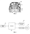
FIG. 4 is a schematic illustrating a control circuit of the gas spring fastener driver ofFIG. 1 . - Before any embodiments of the invention are explained in detail, it is to be understood that the invention is not limited in its application to the details of construction and the arrangement of components set forth in the following description or illustrated in the following drawings. The invention is capable of other embodiments and of being practiced or of being carried out in various ways. Also, it is to be understood that the phraseology and terminology used herein is for the purpose of description and should not be regarded as limiting.
- With reference to
FIGS. 1 and2 , a gas spring-poweredfastener driver 10 is operable to drive fasteners (e.g., nails, tacks, staples, etc.) held within a magazine (not shown) into a workpiece. Thefastener driver 10 includes a cylinder 18 (FIG. 2 ) and amoveable drive piston 22 positioned within thecylinder 18. Thefastener driver 10 also includes adriver blade 26 that is attached to thepiston 22 for movement therewith. Thefastener driver 10 does not require an external source of air pressure, but rather includes a storage chamber cylinder 30 of pressurized gas (e.g., compressed air) in fluid communication with a portion of thecylinder 18 above thedrive piston 22. The portion of thecylinder 18 beneath thedrive piston 22, however, is in fluid communication with ambient air at atmospheric pressure. In the illustrated embodiment, thecylinder 18 anddriver piston 22 are positioned within and coaxial with the storage chamber cylinder 30. - With reference to
FIGS. 2 and3 , thecylinder 18 and thedriver blade 26 define a drivingaxis 38, and during a driving cycle thedriver blade 26 andpiston 22 are moveable between a retracted position (e.g., a top dead center position within the cylinder 18) and an extended, driven position (e.g., a bottom dead center position within the cylinder 18). As shown inFIG. 2 , thefastener driver 10 further includes alifter assembly 42, which is powered by a motor 46 (FIGS. 1 and4 ), and which is operable to return thedriver blade 26 andpiston 22 from the driven position to a ready (i.e., retracted) position. A battery 50 (FIG. 1 ) is electrically connectable to themotor 46 for supplying electrical power to themotor 46. In alternative embodiments, the driver may be powered from an AC voltage input (i.e., from a wall outlet). - In operation of the
fastener driver 10, thelifter assembly 42 drives thepiston 22 and thedriver blade 26 to the retracted or ready position by energizing themotor 46. As thepiston 22 and thedriver blade 26 are driven to the ready position, the gas above thepiston 22 and the gas within the storage chamber cylinder 30 is compressed. Once in the ready position, thepiston 22 and thedriver blade 26 are held in position until released by user activation of a trigger (FIG. 1 ). When released, the compressed gas above thepiston 22 and within the storage chamber 30 drives thepiston 22 and thedriver blade 26 to the driven position, thereby driving a fastener into a workpiece. - As shown in
FIG. 4 , thefastener driver 10 includes a pressure sensor 54 (e.g., a pressure transducer or switch) to determine and/or detect the pressure of the compressed gas within thecylinders 18, 30 and a low-pressure indicator 58 (e.g., an LED) to alert the user of thefastener driver 10 of a low pressure condition in thecylinders 18, 30. More specifically, acontroller 62 in thefastener driver 10 compares the output of thepressure sensor 54 to a predetermined threshold pressure, below which thecontroller 62 activates theindicator 58. - In some embodiments, the
controller 62 may use other techniques to determine the pressure of the compressed gas in thecylinders 18, 30. For example, thecontroller 62 may monitor a current draw on themotor 46 when operating thelifter assembly 42 to return thedriver blade 26 andpiston 22 to the ready position which, using an algorithm, can be interpolated to pressure in thecylinders 18, 30. When thecontroller 62 determines that the current (and/or power) draw on themotor 46 is below a predetermined threshold indicating that the pressure of compressed gas in thecylinders 18, 30 has fallen below a predetermined pressure threshold, thecontroller 62 may activate the low-pressure indicator 58 to provide a low-pressure alert to the user. In other words, thecontroller 62 is operable to correlate the current, voltage, and/or power, consumed by themotor 46 to a corresponding pressure value within thecylinders 18, 30. - With reference to
FIG. 3 , thefastener driver 10 further includes afill valve 66 coupled to anend cap 70 of the storage chamber cylinder 30. Thefill valve 66 is configured to be selectively connected with a gas fitting (not shown) which, in turn, is fluidly connected with a source of compressed gas (e.g., an air compressor, etc.). When connected with the source of compressed gas via the gas fitting, thefill valve 66 permits the storage chamber cylinder 30 to be refilled or recharged with compressed gas if prior leakage has occurred, as communicated to the user by activation of the low-pressure indicator 58. The storage chamber cylinder 30 may be filled to a desired pressure between approximately 90 psi and approximately 150 psi (e.g., approximately 120 psi). In some embodiments, the pressure may be less than 100 psi and greater than 150 psi. In some embodiments, thefill valve 66 may be configured as a Schrader valve. In other embodiments, thefill valve 66 is configured as a Presta valve, Dunlop valve, or other similar pneumatic fill valve. Thefill valve 66 also allows a user to measure and check the pressure within the storage chamber cylinder 30 with any standard pressure gauge device. - Various features of the invention are set forth in the following claims.
Claims (15)
- A fastener driver (10) comprising:a cylinder (18);a drive piston (22) positioned within the cylinder;a driver blade (26) attached to the drive piston (22) and movable from a retracted position to an extended, driven position for driving a fastener into a workpiece;a gas spring mechanism for driving the driver blade (26) from the retracted position to the driven position, the gas spring mechanism including a storage chamber cylinder (30) containing a pressurized gas, the storage chamber cylinder being in fluid communication with a portion of the cylinder (18) above the drive piston, the portion of the cylinder (18) beneath the drive piston being in fluid communication with ambient air at atmospheric pressure, the cylinder (18) and the driver piston (22) being positioned within and coaxial with the storage chamber cylinder (30);means for determining a pressure (54) in the storage cylinder chamber; andan indicator (58) activated in response to the determined pressure in the storage cylinder chamber being less than a predetermined pressure value.
- The fastener driver of claim 1, wherein the pressure determining means includes a pressure sensor (54) or a pressure switch; and
optionally,
the pressure sensor is in fluid communication with the storage chamber cylinder (30) to detect the pressure of the pressurized gas therein. - The fastener driver of claim 2, further comprising a controller (62) to which both the pressure sensor (54) and the indicator (58) are electrically connected; and
optionally,
the pressure sensor outputs a signal to the controller that is proportional to the pressure of the pressurized gas in the storage chamber cylinder (30). - The fastener driver of claim 3, wherein the signal is a variable voltage signal.
- The fastener driver of claim 3, wherein the controller (62) interpolates the signal into a measured pressure value, and wherein the controller includes a comparator that compares the measured pressure value to the predetermined pressure value.
- The fastener driver of claim 5, wherein the controller (62) activates the indicator (58) in response to the measured pressure value being less than the predetermined pressure value.
- The fastener driver of claim 1, wherein the indicator is a light-emitting diode.
- The fastener driver of claim 1, further comprising
a lifter mechanism (42) for moving the driver blade (26) from the driven position toward the retracted position, the lifter mechanism including a motor (46), and
a controller (62) electrically connected with the motor to monitor a current draw thereof,
wherein the pressure determining means (54) includes an algorithm stored in the controller for converting the current draw into the determined pressure in the storage chamber cylinder (30). - A method of operating a fastener driver (10) having a cylinder (18) and a drive piston (22) positioned within the cylinder, the method comprising:initiating a fastener driving operation by moving a driver blade (26) attached to the drive piston, with a gas spring mechanism including a storage chamber cylinder (30) containing a pressurized gas, from a retracted position toward a driven position, the storage chamber cylinder being in fluid communication with a portion of the cylinder above the drive piston, the portion of the cylinder beneath the drive piston being in fluid communication with ambient air at atmospheric pressure, the cylinder (18) and the driver piston (22) being positioned within and coaxial with the storage chamber cylinder (30);determining a pressure of pressurized gas in a storage cylinder chamber of the gas spring mechanism; andindicating to a user of the fastener driver when the determined pressure in the storage chamber cylinder is less than a predetermined pressure value.
- The method of claim 9, wherein the pressure of the pressurized gas is determined by a pressure sensor (54) or a pressure switch.
- The method of claim 10, further comprising outputting a signal from the pressure sensor (54) to a controller (62) that is proportional to the pressure of the pressurized gas in the storage chamber cylinder (30).
- The method of claim 11, further comprising interpolating the signal, with the controller (62), into a measured pressure value.
- The method of claim 12, further comprising comparing the measured pressure value, with the controller (62), to the predetermined pressure value; and
optionally,
indicating to the user of the fastener driver when the measured pressure value in the storage chamber cylinder (30) is less than the predetermined pressure value includes activating a light-emitting diode. - The method of claim 9, wherein the pressure of the pressurized gas is determined by monitoring a current draw of a motor (46), which is operable to move the driver blade (26) from the driven position toward the retracted position; and
optionally,
the method further comprises converting the current draw into a measured pressure value in the storage chamber cylinder (30) using an algorithm stored in the controller (62). - The method of claim 14, further comprising comparing the measured pressure value, with the controller (62), to the predetermined pressure value; and
optionally,
indicating to the user of the fastener driver when the measured pressure value in the storage chamber cylinder (30) is less than a predetermined pressure value includes activating a light-emitting diode.
Applications Claiming Priority (2)
| Application Number | Priority Date | Filing Date | Title |
|---|---|---|---|
| US201662419801P | 2016-11-09 | 2016-11-09 | |
| US201662419863P | 2016-11-09 | 2016-11-09 |
Publications (2)
| Publication Number | Publication Date |
|---|---|
| EP3321037A1 EP3321037A1 (en) | 2018-05-16 |
| EP3321037B1 true EP3321037B1 (en) | 2020-10-07 |
Family
ID=60301852
Family Applications (1)
| Application Number | Title | Priority Date | Filing Date |
|---|---|---|---|
| EP17200927.6A Active EP3321037B1 (en) | 2016-11-09 | 2017-11-09 | Control system for gas spring fastener driver |
Country Status (4)
| Country | Link |
|---|---|
| US (1) | US10710227B2 (en) |
| EP (1) | EP3321037B1 (en) |
| CN (1) | CN108058142A (en) |
| CA (1) | CA2985234C (en) |
Families Citing this family (15)
| Publication number | Priority date | Publication date | Assignee | Title |
|---|---|---|---|---|
| WO2016136632A1 (en) * | 2015-02-26 | 2016-09-01 | 日立工機株式会社 | Driving machine |
| US10632600B2 (en) | 2016-11-09 | 2020-04-28 | Tti (Macao Commercial Offshore) Limited | Cylinder assembly for gas spring fastener driver |
| CN108068059B (en) * | 2016-11-09 | 2022-07-08 | 创科无线普通合伙 | Jam release and lifter mechanism for gas spring fastener driver |
| EP3348368B1 (en) * | 2017-01-13 | 2021-02-03 | Illinois Tool Works, Inc. | Driving module with improved magazine |
| USD900575S1 (en) | 2018-09-26 | 2020-11-03 | Milwaukee Electric Tool Corporation | Powered fastener driver |
| US11130221B2 (en) | 2019-01-31 | 2021-09-28 | Milwaukee Electric Tool Corporation | Powered fastener driver |
| EP3962698A4 (en) | 2019-06-14 | 2023-09-20 | Milwaukee Electric Tool Corporation | Lifter mechanism for a powered fastener driver |
| US11951601B2 (en) | 2019-06-14 | 2024-04-09 | Milwaukee Electric Tool Corporation | Lifter mechanism for a powered fastener driver |
| US20220219301A1 (en) | 2019-06-14 | 2022-07-14 | Milwaukee Electric Tool Corporation | Lifter mechanism for a powered fastener driver |
| TWM599725U (en) * | 2019-07-30 | 2020-08-11 | 鑽全實業股份有限公司 | Air cylinder nail gun system |
| CA3163820A1 (en) * | 2020-02-05 | 2021-08-12 | Alexander L. Carrier | Gas spring fastener driving tool with fill valve located in an end cap |
| CN219255473U (en) | 2020-03-25 | 2023-06-27 | 米沃奇电动工具公司 | Fastener driver |
| JP2023064270A (en) * | 2021-10-26 | 2023-05-11 | 株式会社マキタ | driving tool |
| TWM634314U (en) * | 2021-12-28 | 2022-11-21 | 鑽全實業股份有限公司 | Pneumatic powered nail gun capable of replenishing gas |
| US20220371167A1 (en) * | 2022-08-01 | 2022-11-24 | David D. Bradley | Working cylinder for power tool with piston lubricating system |
Family Cites Families (22)
| Publication number | Priority date | Publication date | Assignee | Title |
|---|---|---|---|---|
| US3782250A (en) * | 1971-11-03 | 1974-01-01 | Microdot Inc | Control system |
| US4104907A (en) * | 1976-10-26 | 1978-08-08 | Megasystems, Inc. | Indicated horsepower measurement system for piston engines |
| JPS5492382A (en) * | 1977-12-29 | 1979-07-21 | Nissan Motor | Pressure detector |
| US5027015A (en) * | 1989-09-14 | 1991-06-25 | Motorola, Inc. | Non-linear conversion of input from a sensor to an output with two different slopes |
| US5187985A (en) * | 1991-09-19 | 1993-02-23 | Honeywell Inc. | Amplified pressure transducer |
| JPH05264391A (en) * | 1992-03-19 | 1993-10-12 | Unisia Jecs Corp | Pressure sensor |
| US6123241A (en) | 1995-05-23 | 2000-09-26 | Applied Tool Development Corporation | Internal combustion powered tool |
| JP3676879B2 (en) * | 1995-07-25 | 2005-07-27 | 株式会社マキタ | Fastener driving tool |
| US7225959B2 (en) | 2001-04-30 | 2007-06-05 | Black & Decker, Inc. | Portable, battery-powered air compressor for a pneumatic tool system |
| TW570864B (en) * | 2001-05-17 | 2004-01-11 | Li-Jeng Jang | Portable pneumatic tool |
| DE10254965B4 (en) * | 2002-11-26 | 2021-05-06 | Hilti Aktiengesellschaft | Internal combustion-powered setting tool |
| US6722550B1 (en) * | 2003-05-09 | 2004-04-20 | Illinois Tool Works Inc. | Fuel level indicator for combustion tools |
| JP2012187640A (en) * | 2009-07-24 | 2012-10-04 | Makita Corp | Hammering tool |
| US8079504B1 (en) | 2010-11-04 | 2011-12-20 | Tricord Solutions, Inc. | Fastener driving apparatus |
| US9463560B2 (en) * | 2011-10-03 | 2016-10-11 | Illinois Tool Works Inc. | Portable pressurized power source for fastener driving tool |
| DE102012210347A1 (en) * | 2012-06-19 | 2013-12-19 | Hilti Aktiengesellschaft | Setting tool and control method |
| EP3036069B1 (en) * | 2013-08-22 | 2020-11-11 | Techtronic Power Tools Technology Limited | Pneumatic fastener driver |
| US9662777B2 (en) * | 2013-08-22 | 2017-05-30 | Techtronic Power Tools Technology Limited | Pneumatic fastener driver |
| JP6100680B2 (en) | 2013-12-11 | 2017-03-22 | 株式会社マキタ | Driving tool |
| CA2981167C (en) | 2015-03-30 | 2019-10-08 | Senco Brands, Inc. | Lift mechanism for framing nailer |
| JP6485544B2 (en) * | 2015-06-10 | 2019-03-20 | 工機ホールディングス株式会社 | Driving machine |
| CN107526474B (en) * | 2017-08-31 | 2021-12-28 | 京东方科技集团股份有限公司 | Pressure sensing module integrated with fingerprint identification function, driving method and display device |
-
2017
- 2017-11-09 CA CA2985234A patent/CA2985234C/en active Active
- 2017-11-09 US US15/807,730 patent/US10710227B2/en active Active
- 2017-11-09 CN CN201711098184.XA patent/CN108058142A/en active Pending
- 2017-11-09 EP EP17200927.6A patent/EP3321037B1/en active Active
Non-Patent Citations (1)
| Title |
|---|
| None * |
Also Published As
| Publication number | Publication date |
|---|---|
| CA2985234C (en) | 2023-06-20 |
| CA2985234A1 (en) | 2018-05-09 |
| US10710227B2 (en) | 2020-07-14 |
| EP3321037A1 (en) | 2018-05-16 |
| US20180126530A1 (en) | 2018-05-10 |
| CN108058142A (en) | 2018-05-22 |
Similar Documents
| Publication | Publication Date | Title |
|---|---|---|
| EP3321037B1 (en) | Control system for gas spring fastener driver | |
| US7793811B1 (en) | Fastener driving apparatus | |
| US8800834B2 (en) | Fastener driving apparatus | |
| AU2018200778B2 (en) | Portable pressurized power source for fastener driving tool | |
| US20110095064A1 (en) | Fuel level monitoring system for combustion-powered tools | |
| US20180036870A1 (en) | Driving machine | |
| US20150158160A1 (en) | Driving tool | |
| US20110108600A1 (en) | Fastener Driving Apparatus | |
| CA2816941C (en) | Portable fastener driving apparatus | |
| US11819989B2 (en) | Powered fastener driver | |
| TW570864B (en) | Portable pneumatic tool | |
| US11358262B2 (en) | Fastener driving apparatus | |
| CA2849481C (en) | Fastener driving tool with portable pressurized power source |
Legal Events
| Date | Code | Title | Description |
|---|---|---|---|
| PUAI | Public reference made under article 153(3) epc to a published international application that has entered the european phase |
Free format text: ORIGINAL CODE: 0009012 |
|
| STAA | Information on the status of an ep patent application or granted ep patent |
Free format text: STATUS: THE APPLICATION HAS BEEN PUBLISHED |
|
| AK | Designated contracting states |
Kind code of ref document: A1 Designated state(s): AL AT BE BG CH CY CZ DE DK EE ES FI FR GB GR HR HU IE IS IT LI LT LU LV MC MK MT NL NO PL PT RO RS SE SI SK SM TR |
|
| AX | Request for extension of the european patent |
Extension state: BA ME |
|
| STAA | Information on the status of an ep patent application or granted ep patent |
Free format text: STATUS: REQUEST FOR EXAMINATION WAS MADE |
|
| RIN1 | Information on inventor provided before grant (corrected) |
Inventor name: SCOTT, ZACHARY Inventor name: NAMOUZ, ESSAM Inventor name: SCHNELL, JOHN Inventor name: POMEROY, EDWARD A. |
|
| 17P | Request for examination filed |
Effective date: 20180917 |
|
| RBV | Designated contracting states (corrected) |
Designated state(s): AL AT BE BG CH CY CZ DE DK EE ES FI FR GB GR HR HU IE IS IT LI LT LU LV MC MK MT NL NO PL PT RO RS SE SI SK SM TR |
|
| GRAP | Despatch of communication of intention to grant a patent |
Free format text: ORIGINAL CODE: EPIDOSNIGR1 |
|
| STAA | Information on the status of an ep patent application or granted ep patent |
Free format text: STATUS: GRANT OF PATENT IS INTENDED |
|
| INTG | Intention to grant announced |
Effective date: 20200416 |
|
| GRAS | Grant fee paid |
Free format text: ORIGINAL CODE: EPIDOSNIGR3 |
|
| GRAA | (expected) grant |
Free format text: ORIGINAL CODE: 0009210 |
|
| STAA | Information on the status of an ep patent application or granted ep patent |
Free format text: STATUS: THE PATENT HAS BEEN GRANTED |
|
| AK | Designated contracting states |
Kind code of ref document: B1 Designated state(s): AL AT BE BG CH CY CZ DE DK EE ES FI FR GB GR HR HU IE IS IT LI LT LU LV MC MK MT NL NO PL PT RO RS SE SI SK SM TR |
|
| REG | Reference to a national code |
Ref country code: GB Ref legal event code: FG4D |
|
| REG | Reference to a national code |
Ref country code: CH Ref legal event code: EP Ref country code: AT Ref legal event code: REF Ref document number: 1320632 Country of ref document: AT Kind code of ref document: T Effective date: 20201015 |
|
| REG | Reference to a national code |
Ref country code: DE Ref legal event code: R096 Ref document number: 602017024931 Country of ref document: DE |
|
| REG | Reference to a national code |
Ref country code: IE Ref legal event code: FG4D |
|
| RAP2 | Party data changed (patent owner data changed or rights of a patent transferred) |
Owner name: TTI (MACAO COMMERCIAL OFFSHORE) LIMITED |
|
| REG | Reference to a national code |
Ref country code: NL Ref legal event code: MP Effective date: 20201007 |
|
| REG | Reference to a national code |
Ref country code: AT Ref legal event code: MK05 Ref document number: 1320632 Country of ref document: AT Kind code of ref document: T Effective date: 20201007 |
|
| PG25 | Lapsed in a contracting state [announced via postgrant information from national office to epo] |
Ref country code: NO Free format text: LAPSE BECAUSE OF FAILURE TO SUBMIT A TRANSLATION OF THE DESCRIPTION OR TO PAY THE FEE WITHIN THE PRESCRIBED TIME-LIMIT Effective date: 20210107 Ref country code: RS Free format text: LAPSE BECAUSE OF FAILURE TO SUBMIT A TRANSLATION OF THE DESCRIPTION OR TO PAY THE FEE WITHIN THE PRESCRIBED TIME-LIMIT Effective date: 20201007 Ref country code: PT Free format text: LAPSE BECAUSE OF FAILURE TO SUBMIT A TRANSLATION OF THE DESCRIPTION OR TO PAY THE FEE WITHIN THE PRESCRIBED TIME-LIMIT Effective date: 20210208 Ref country code: GR Free format text: LAPSE BECAUSE OF FAILURE TO SUBMIT A TRANSLATION OF THE DESCRIPTION OR TO PAY THE FEE WITHIN THE PRESCRIBED TIME-LIMIT Effective date: 20210108 Ref country code: FI Free format text: LAPSE BECAUSE OF FAILURE TO SUBMIT A TRANSLATION OF THE DESCRIPTION OR TO PAY THE FEE WITHIN THE PRESCRIBED TIME-LIMIT Effective date: 20201007 |
|
| REG | Reference to a national code |
Ref country code: LT Ref legal event code: MG4D |
|
| PG25 | Lapsed in a contracting state [announced via postgrant information from national office to epo] |
Ref country code: SE Free format text: LAPSE BECAUSE OF FAILURE TO SUBMIT A TRANSLATION OF THE DESCRIPTION OR TO PAY THE FEE WITHIN THE PRESCRIBED TIME-LIMIT Effective date: 20201007 Ref country code: ES Free format text: LAPSE BECAUSE OF FAILURE TO SUBMIT A TRANSLATION OF THE DESCRIPTION OR TO PAY THE FEE WITHIN THE PRESCRIBED TIME-LIMIT Effective date: 20201007 Ref country code: AT Free format text: LAPSE BECAUSE OF FAILURE TO SUBMIT A TRANSLATION OF THE DESCRIPTION OR TO PAY THE FEE WITHIN THE PRESCRIBED TIME-LIMIT Effective date: 20201007 Ref country code: BG Free format text: LAPSE BECAUSE OF FAILURE TO SUBMIT A TRANSLATION OF THE DESCRIPTION OR TO PAY THE FEE WITHIN THE PRESCRIBED TIME-LIMIT Effective date: 20210107 Ref country code: IS Free format text: LAPSE BECAUSE OF FAILURE TO SUBMIT A TRANSLATION OF THE DESCRIPTION OR TO PAY THE FEE WITHIN THE PRESCRIBED TIME-LIMIT Effective date: 20210207 Ref country code: LV Free format text: LAPSE BECAUSE OF FAILURE TO SUBMIT A TRANSLATION OF THE DESCRIPTION OR TO PAY THE FEE WITHIN THE PRESCRIBED TIME-LIMIT Effective date: 20201007 Ref country code: PL Free format text: LAPSE BECAUSE OF FAILURE TO SUBMIT A TRANSLATION OF THE DESCRIPTION OR TO PAY THE FEE WITHIN THE PRESCRIBED TIME-LIMIT Effective date: 20201007 |
|
| PG25 | Lapsed in a contracting state [announced via postgrant information from national office to epo] |
Ref country code: NL Free format text: LAPSE BECAUSE OF FAILURE TO SUBMIT A TRANSLATION OF THE DESCRIPTION OR TO PAY THE FEE WITHIN THE PRESCRIBED TIME-LIMIT Effective date: 20201007 Ref country code: HR Free format text: LAPSE BECAUSE OF FAILURE TO SUBMIT A TRANSLATION OF THE DESCRIPTION OR TO PAY THE FEE WITHIN THE PRESCRIBED TIME-LIMIT Effective date: 20201007 |
|
| REG | Reference to a national code |
Ref country code: CH Ref legal event code: PL |
|
| REG | Reference to a national code |
Ref country code: DE Ref legal event code: R097 Ref document number: 602017024931 Country of ref document: DE |
|
| PG25 | Lapsed in a contracting state [announced via postgrant information from national office to epo] |
Ref country code: LU Free format text: LAPSE BECAUSE OF NON-PAYMENT OF DUE FEES Effective date: 20201109 Ref country code: LT Free format text: LAPSE BECAUSE OF FAILURE TO SUBMIT A TRANSLATION OF THE DESCRIPTION OR TO PAY THE FEE WITHIN THE PRESCRIBED TIME-LIMIT Effective date: 20201007 Ref country code: MC Free format text: LAPSE BECAUSE OF FAILURE TO SUBMIT A TRANSLATION OF THE DESCRIPTION OR TO PAY THE FEE WITHIN THE PRESCRIBED TIME-LIMIT Effective date: 20201007 Ref country code: CZ Free format text: LAPSE BECAUSE OF FAILURE TO SUBMIT A TRANSLATION OF THE DESCRIPTION OR TO PAY THE FEE WITHIN THE PRESCRIBED TIME-LIMIT Effective date: 20201007 Ref country code: EE Free format text: LAPSE BECAUSE OF FAILURE TO SUBMIT A TRANSLATION OF THE DESCRIPTION OR TO PAY THE FEE WITHIN THE PRESCRIBED TIME-LIMIT Effective date: 20201007 Ref country code: SM Free format text: LAPSE BECAUSE OF FAILURE TO SUBMIT A TRANSLATION OF THE DESCRIPTION OR TO PAY THE FEE WITHIN THE PRESCRIBED TIME-LIMIT Effective date: 20201007 Ref country code: SK Free format text: LAPSE BECAUSE OF FAILURE TO SUBMIT A TRANSLATION OF THE DESCRIPTION OR TO PAY THE FEE WITHIN THE PRESCRIBED TIME-LIMIT Effective date: 20201007 Ref country code: RO Free format text: LAPSE BECAUSE OF FAILURE TO SUBMIT A TRANSLATION OF THE DESCRIPTION OR TO PAY THE FEE WITHIN THE PRESCRIBED TIME-LIMIT Effective date: 20201007 |
|
| REG | Reference to a national code |
Ref country code: BE Ref legal event code: MM Effective date: 20201130 |
|
| PLBE | No opposition filed within time limit |
Free format text: ORIGINAL CODE: 0009261 |
|
| STAA | Information on the status of an ep patent application or granted ep patent |
Free format text: STATUS: NO OPPOSITION FILED WITHIN TIME LIMIT |
|
| PG25 | Lapsed in a contracting state [announced via postgrant information from national office to epo] |
Ref country code: LI Free format text: LAPSE BECAUSE OF NON-PAYMENT OF DUE FEES Effective date: 20201130 Ref country code: DK Free format text: LAPSE BECAUSE OF FAILURE TO SUBMIT A TRANSLATION OF THE DESCRIPTION OR TO PAY THE FEE WITHIN THE PRESCRIBED TIME-LIMIT Effective date: 20201007 Ref country code: CH Free format text: LAPSE BECAUSE OF NON-PAYMENT OF DUE FEES Effective date: 20201130 |
|
| 26N | No opposition filed |
Effective date: 20210708 |
|
| PG25 | Lapsed in a contracting state [announced via postgrant information from national office to epo] |
Ref country code: AL Free format text: LAPSE BECAUSE OF FAILURE TO SUBMIT A TRANSLATION OF THE DESCRIPTION OR TO PAY THE FEE WITHIN THE PRESCRIBED TIME-LIMIT Effective date: 20201007 Ref country code: IE Free format text: LAPSE BECAUSE OF NON-PAYMENT OF DUE FEES Effective date: 20201109 Ref country code: IT Free format text: LAPSE BECAUSE OF FAILURE TO SUBMIT A TRANSLATION OF THE DESCRIPTION OR TO PAY THE FEE WITHIN THE PRESCRIBED TIME-LIMIT Effective date: 20201007 |
|
| PG25 | Lapsed in a contracting state [announced via postgrant information from national office to epo] |
Ref country code: SI Free format text: LAPSE BECAUSE OF FAILURE TO SUBMIT A TRANSLATION OF THE DESCRIPTION OR TO PAY THE FEE WITHIN THE PRESCRIBED TIME-LIMIT Effective date: 20201007 |
|
| PG25 | Lapsed in a contracting state [announced via postgrant information from national office to epo] |
Ref country code: IS Free format text: LAPSE BECAUSE OF FAILURE TO SUBMIT A TRANSLATION OF THE DESCRIPTION OR TO PAY THE FEE WITHIN THE PRESCRIBED TIME-LIMIT Effective date: 20210207 Ref country code: TR Free format text: LAPSE BECAUSE OF FAILURE TO SUBMIT A TRANSLATION OF THE DESCRIPTION OR TO PAY THE FEE WITHIN THE PRESCRIBED TIME-LIMIT Effective date: 20201007 Ref country code: MT Free format text: LAPSE BECAUSE OF FAILURE TO SUBMIT A TRANSLATION OF THE DESCRIPTION OR TO PAY THE FEE WITHIN THE PRESCRIBED TIME-LIMIT Effective date: 20201007 Ref country code: CY Free format text: LAPSE BECAUSE OF FAILURE TO SUBMIT A TRANSLATION OF THE DESCRIPTION OR TO PAY THE FEE WITHIN THE PRESCRIBED TIME-LIMIT Effective date: 20201007 |
|
| PG25 | Lapsed in a contracting state [announced via postgrant information from national office to epo] |
Ref country code: MK Free format text: LAPSE BECAUSE OF FAILURE TO SUBMIT A TRANSLATION OF THE DESCRIPTION OR TO PAY THE FEE WITHIN THE PRESCRIBED TIME-LIMIT Effective date: 20201007 |
|
| PG25 | Lapsed in a contracting state [announced via postgrant information from national office to epo] |
Ref country code: BE Free format text: LAPSE BECAUSE OF NON-PAYMENT OF DUE FEES Effective date: 20201130 |
|
| PGFP | Annual fee paid to national office [announced via postgrant information from national office to epo] |
Ref country code: GB Payment date: 20231127 Year of fee payment: 7 |
|
| PGFP | Annual fee paid to national office [announced via postgrant information from national office to epo] |
Ref country code: FR Payment date: 20231127 Year of fee payment: 7 Ref country code: DE Payment date: 20231129 Year of fee payment: 7 |