EP3321031B1 - Apparatus comprising a tool changer device and a linearly translating head. - Google Patents
Apparatus comprising a tool changer device and a linearly translating head. Download PDFInfo
- Publication number
- EP3321031B1 EP3321031B1 EP17001833.7A EP17001833A EP3321031B1 EP 3321031 B1 EP3321031 B1 EP 3321031B1 EP 17001833 A EP17001833 A EP 17001833A EP 3321031 B1 EP3321031 B1 EP 3321031B1
- Authority
- EP
- European Patent Office
- Prior art keywords
- gripper
- hole
- axis
- tool
- rod
- Prior art date
- Legal status (The legal status is an assumption and is not a legal conclusion. Google has not performed a legal analysis and makes no representation as to the accuracy of the status listed.)
- Active
Links
- 230000000903 blocking effect Effects 0.000 claims description 15
- 230000000295 complement effect Effects 0.000 claims description 2
- 238000003801 milling Methods 0.000 description 2
- 230000001419 dependent effect Effects 0.000 description 1
- 238000000605 extraction Methods 0.000 description 1
- 238000003780 insertion Methods 0.000 description 1
- 230000037431 insertion Effects 0.000 description 1
- 238000000034 method Methods 0.000 description 1
- 230000001681 protective effect Effects 0.000 description 1
- 230000000284 resting effect Effects 0.000 description 1
Images


Classifications
-
- B—PERFORMING OPERATIONS; TRANSPORTING
- B23—MACHINE TOOLS; METAL-WORKING NOT OTHERWISE PROVIDED FOR
- B23Q—DETAILS, COMPONENTS, OR ACCESSORIES FOR MACHINE TOOLS, e.g. ARRANGEMENTS FOR COPYING OR CONTROLLING; MACHINE TOOLS IN GENERAL CHARACTERISED BY THE CONSTRUCTION OF PARTICULAR DETAILS OR COMPONENTS; COMBINATIONS OR ASSOCIATIONS OF METAL-WORKING MACHINES, NOT DIRECTED TO A PARTICULAR RESULT
- B23Q3/00—Devices holding, supporting, or positioning work or tools, of a kind normally removable from the machine
- B23Q3/155—Arrangements for automatic insertion or removal of tools, e.g. combined with manual handling
- B23Q3/1552—Arrangements for automatic insertion or removal of tools, e.g. combined with manual handling parts of devices for automatically inserting or removing tools
- B23Q3/1554—Transfer mechanisms, e.g. tool gripping arms; Drive mechanisms therefore
- B23Q2003/155414—Transfer mechanisms, e.g. tool gripping arms; Drive mechanisms therefore the transfer mechanism comprising two or more grippers
- B23Q2003/155418—Transfer mechanisms, e.g. tool gripping arms; Drive mechanisms therefore the transfer mechanism comprising two or more grippers the grippers moving together
-
- B—PERFORMING OPERATIONS; TRANSPORTING
- B23—MACHINE TOOLS; METAL-WORKING NOT OTHERWISE PROVIDED FOR
- B23Q—DETAILS, COMPONENTS, OR ACCESSORIES FOR MACHINE TOOLS, e.g. ARRANGEMENTS FOR COPYING OR CONTROLLING; MACHINE TOOLS IN GENERAL CHARACTERISED BY THE CONSTRUCTION OF PARTICULAR DETAILS OR COMPONENTS; COMBINATIONS OR ASSOCIATIONS OF METAL-WORKING MACHINES, NOT DIRECTED TO A PARTICULAR RESULT
- B23Q3/00—Devices holding, supporting, or positioning work or tools, of a kind normally removable from the machine
- B23Q3/155—Arrangements for automatic insertion or removal of tools, e.g. combined with manual handling
- B23Q3/1552—Arrangements for automatic insertion or removal of tools, e.g. combined with manual handling parts of devices for automatically inserting or removing tools
- B23Q3/1554—Transfer mechanisms, e.g. tool gripping arms; Drive mechanisms therefore
- B23Q2003/155414—Transfer mechanisms, e.g. tool gripping arms; Drive mechanisms therefore the transfer mechanism comprising two or more grippers
- B23Q2003/155453—Transfer mechanisms, e.g. tool gripping arms; Drive mechanisms therefore the transfer mechanism comprising two or more grippers including different gripper configurations for holding differently-configured tools
Definitions
- the present invention relates to an apparatus including a tool changer device and a linearly translating head.
- the present invention relates to a mechanical and fully autonomous tool changer device, mounted on a linearly translating head and having a contrasting surface, to which the device is brought automatically and alternatively into contact, or in close proximity, without contact, by means of movements in a direction essentially at a right angle to the direction of translation of the head.
- Said head is provided with a cam exchanger mechanism, i.e. brushless motor means, that cause an ordered series of intermittent linear and rotary movements of an output shaft, to which is fixed a rigid arm, extending in at least one radial direction and carrying at least one tool-holder cone gripper.
- a cam exchanger mechanism i.e. brushless motor means, that cause an ordered series of intermittent linear and rotary movements of an output shaft, to which is fixed a rigid arm, extending in at least one radial direction and carrying at least one tool-holder cone gripper.
- Tool changer devices are known for example from Patent Document EP-A-2 803 444 .
- cones used on these machines are:
- the main object of the present invention is to provide a tool changer device of the type described, wherein at least one gripper arm can indifferently grip and block, for example, the cones ISO 50, ISO 40 and HSK 63, and possibly even the cones Capto C8 and C10, without requiring any initial pre-setting.
- a further object of the present invention is to provide a tool changer device of the type described, which has a compact, small and simplified structure.
- the present invention provides an apparatus, the essential characteristic of which is the subject of the main claim, while further advantageous characteristics of the invention are described in the dependent claims.
- the number 10 indicates the tool changer device as a whole, according to the afore-mentioned example of an embodiment of the invention.
- said mechanical and fully autonomous tool changer device 10 is mounted on a linearly translating head (of an already known type and not shown), for example in the direction of the Y axis, and has a contrasting surface S, against which the device is brought automatically and alternatively into contact, or in close proximity, without contact, by means of movements in a direction, for example X, essentially at a right angle to said direction of translation of the head.
- Said head is provided, in a known manner and therefore not shown, with a cam exchanger mechanism, respectively brushless motor means, that cause an ordered series of intermittent linear and rotary movements of an output shaft A, with an axis X-X to which is fixed a rigid arm 10.1, extending in at least one radial direction and carrying at least one tool-holder cone gripper.
- said arm 10.1 is symmetrically extended in two opposing radial directions with respect to said shaft A and supports, at a first free end, a first gripper 11 of a first tool-holder PU1 and, at a second free end, a second gripper 11 of a second tool-holder PU2, where the external diameter of said first tool-holder PU1 is greater than the external diameter of said second tool-holder PU2.
- each gripper 11 comprises:
- each double-joint lever 14.1 is partially resting against a respective outer protective cover 14.8, placed substantially flush with said double-joint lever and fixed to said box-type body 12.
- said rod member 17.1 of said shutter means 17 has, around said at least one through hole 15.2 of said blocking means 15, a surface portion that is conically countersunk towards the free end of the respective rod and, correspondingly, said at least one through hole 15.2 of said blocking means 15 has a conically countersunk circumferential portion with a shape that is substantially complementary to that of said conically countersunk surface portion of said rod member 17.1.
- said rigid arm 10.1 is symmetrically extended in two opposing radial directions with respect to the axis X-X of said shaft A and supports, at a first free end, a first gripper 11 of a first tool-holder PU1 and, at a second free end, a second gripper 11 of a second tool-holder PU2, where the external diameter of said first tool-holder PU1 is greater than the external diameter of said second tool-holder PU2.
- first gripper 11 and said second gripper 11 each comprise:
- said rod member 17.1 of said gripper 11 extends through a through hole 15.2 of said pair of through holes, near said shaft A, when said slide 13 is in said advanced position, and said rod member 17.1 of said gripper 11 extends through a through hole 15.2 of said pair of through holes, distal to said shaft A, when said slide 13 is in said set-back position.
- an aperture 15.3 is provided between said at least two through holes 15.2 of said blocking means 15 substantially in said direction (r), and permits the free passage of said rod member 17.1 from one hole to the other 15.2 of said at least two holes 15.2 and vice-versa.
- each gripper 11 mounted on the exchanger arm 10.1 has two spring-loaded clamps 14 that, when gripping a tool, open and adapt to the dimensions of the cone PU1, PU2, respectively.
- said two clamps 14 are blocked by the insertion of the shutter means 17 in the corresponding holes 15.2 of the blocking means 15, so that, during the exchange and translation phase of the exchanger arm 10.1, the tool cones PU1, PU2 are irreversibly blocked.
- the tool changer device achieves the objects set out in the introduction, in a simple, effective and safe manner.
Description
- The present invention relates to an apparatus including a tool changer device and a linearly translating head.
- In particular, the present invention relates to a mechanical and fully autonomous tool changer device, mounted on a linearly translating head and having a contrasting surface, to which the device is brought automatically and alternatively into contact, or in close proximity, without contact, by means of movements in a direction essentially at a right angle to the direction of translation of the head.
- Said head is provided with a cam exchanger mechanism, i.e. brushless motor means, that cause an ordered series of intermittent linear and rotary movements of an output shaft, to which is fixed a rigid arm, extending in at least one radial direction and carrying at least one tool-holder cone gripper.
- Tool changer devices are known for example from Patent Document
EP-A-2 803 444 . - There is a need to use CNC machine tools with different spindle heads, that can be installed on the same machine by means of an automatic head changer device. However, while this procedure is relatively easy to perform in the tool-holder storage unit, since sleeves can be fitted for two or more different types of cone, it is more problematic on the gripper arm, since the cone gripping elements have different sizes.
- Generally, the cones used on these machines are:
- ISO 50 with milling heads for roughing operations;
- ISO 40 with milling heads for finishing operations;
- HSK63 with electro-spindles for finishing operations;
- CAPTO C8 or C1O for turning operations.
- The main object of the present invention is to provide a tool changer device of the type described, wherein at least one gripper arm can indifferently grip and block, for example, the cones ISO 50, ISO 40 and HSK 63, and possibly even the cones Capto C8 and C10, without requiring any initial pre-setting.
- A further object of the present invention is to provide a tool changer device of the type described, which has a compact, small and simplified structure.
- In view of these objects, the present invention provides an apparatus, the essential characteristic of which is the subject of the main claim, while further advantageous characteristics of the invention are described in the dependent claims.
- The present invention will become more apparent from the following detailed description, with reference to the drawing attached hereto, which is purely exemplary and therefore non-limiting, in which:
-
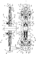
Fig. 1 shows a front elevation view of the device, with parts omitted, according to an example of an embodiment of the present invention, in the condition where two tool-holders are blocked in respective closed grippers; -
Fig. 2 shows a longitudinal cross-section view of the device shown inFig. 1 ; -
Fig. 3 shows a similar view to that ofFig. 1 , in the condition, however, wherein the two tool-holders are free in the respective grippers; -
Fig. 4 shows a longitudinal cross-section view of the device shown inFig. 3 ; -
Fig. 5 shows a similar view to that ofFig. 1 , in the condition, however, wherein the two tool-holders are free and the respective grippers are open; -
Fig. 6 shows a longitudinal cross-section view of the device shown inFig. 5 . - With reference to the drawing, the
number 10 indicates the tool changer device as a whole, according to the afore-mentioned example of an embodiment of the invention. - In particular, said mechanical and fully autonomous
tool changer device 10 is mounted on a linearly translating head (of an already known type and not shown), for example in the direction of the Y axis, and has a contrasting surface S, against which the device is brought automatically and alternatively into contact, or in close proximity, without contact, by means of movements in a direction, for example X, essentially at a right angle to said direction of translation of the head. - Said head is provided, in a known manner and therefore not shown, with a cam exchanger mechanism, respectively brushless motor means, that cause an ordered series of intermittent linear and rotary movements of an output shaft A, with an axis X-X to which is fixed a rigid arm 10.1, extending in at least one radial direction and carrying at least one tool-holder cone gripper. In the example shown, said arm 10.1 is symmetrically extended in two opposing radial directions with respect to said shaft A and supports, at a first free end, a
first gripper 11 of a first tool-holder PU1 and, at a second free end, asecond gripper 11 of a second tool-holder PU2, where the external diameter of said first tool-holder PU1 is greater than the external diameter of said second tool-holder PU2. - In particular each
gripper 11 comprises: - a box-
type body 12, integral with said rigid arm 10.1, closed by means of a removable cover 12.1 and in which, in a free end area, there are provided slide means 13 that can move with a straight-line alternating movement, in the direction of a line (r) essentially at a right angle to said axis X-X, along corresponding sliding guide means 12.2, between a set-back position near said shaft A and an advanced position distal to said shaft A; - a pair of
clamps 14 of saidgripper 11, specularly symmetrical with respect to a plane passing through said axis X-X and said line (r), wherein eachgripper clamp 14 comprises a respective double joint lever 14.1 including a first rod 14.2 and a second rod 14.3 hinged to one another at a respective end, by means of a common pin 14.4 with an axis parallel to said axis X-X, where said first rod 14.2 is hinged, in an intermediate position, by means of a pin 14.5 fixed to said box-type body 12 and having an axis parallel to said axis X-X and, at the opposite end, fixed to saidslide means 13, by means of a pin 14.6 fixed to said slide means 13 and having an axis parallel to said axis X-X, and said second rod 14.3 is hinged, in an intermediate position, by means of a pin 14.7 fixed to said box-type body 12 and having an axis parallel to said axis X-X, where the free end 12.8 of said second rod 14.3 protrudes with respect to said free end of said box-type body 12 and provides a gripping part of thecorresponding clamp 14 of saidgripper 11; - blocking means 15 integral with said slide means 13 and comprising a plate member 15.1 with at least one through hole 15.2 with an axis Z-Z parallel to said axis X-X;
- elastic means 16 that elastically move said slide means 13 towards said advanced position and said
clamps 14 to a mutually near position with gripper closed; - shutter means 17, fixed to said arm 10.1 and comprising a rod member 17.1 extending through said at least one through hole 15.2 of said
blocking means 15 and a corresponding through hole 12.9 provided in said box-type body 12; - elastic means 18 that keep said rod member 17.1 of said shutter means 17 partially extended beyond said hole 12.9 of said box-
type body 12 and passing through said at least one hole 15.2 with interference, when saiddevice 10 is out of contact with said contrasting surface S of said stationary head (Figs. 1, 2 ) while, when saiddevice 10 is in contact with or in close proximity to said contrasting surface S of said head (Figs. 3 - 6 ), said rod 17.1 of said shutter means 17 is re-inserted into said through hole 12.9 of said box-type body 12, opposing the action of saidelastic means 18, and is positioned passing without interference through said at least one hole 15.2. - It will be noted that said second rod 14.3 of each double-joint lever 14.1 is partially resting against a respective outer protective cover 14.8, placed substantially flush with said double-joint lever and fixed to said box-
type body 12. - Furthermore, said rod member 17.1 of said shutter means 17 has, around said at least one through hole 15.2 of said
blocking means 15, a surface portion that is conically countersunk towards the free end of the respective rod and, correspondingly, said at least one through hole 15.2 of saidblocking means 15 has a conically countersunk circumferential portion with a shape that is substantially complementary to that of said conically countersunk surface portion of said rod member 17.1. - With reference to the embodiment of the invention shown in the drawing, as indicated above, said rigid arm 10.1 is symmetrically extended in two opposing radial directions with respect to the axis X-X of said shaft A and supports, at a first free end, a
first gripper 11 of a first tool-holder PU1 and, at a second free end, asecond gripper 11 of a second tool-holder PU2, where the external diameter of said first tool-holder PU1 is greater than the external diameter of said second tool-holder PU2. - It will be noted that when said slide means 13 of said
gripper 11 are in said set-back position, near to said shaft A, they allow the mutual opening of saidclamps 14 of thecorresponding gripper 11 on said tool-holder PU1, PU2, and when said slide means 13 of saidgripper 11 are in said advanced position, distal to said shaft A, they cause the mutual closure of saidclamps 14 of thecorresponding gripper 11 on a tool-holder PU1, PU2. - Furthermore, said
first gripper 11 and saidsecond gripper 11 each comprise: - respective blocking means 15 integral with corresponding slide means 13, wherein a plate member 15.1 has at least two through holes 15.2 with axes Z-Z parallel to said axis X-X and aligned with one another in a direction parallel to said direction (r),
- respective shutter means 17, fixed to a corresponding box-
type body 12, 12.1, wherein a rod member 17.1 extends through one of said at least two through holes 15.2 of saidrespective blocking means 15 and through said through hole 12.9 provided in said box-type body 12. - Moreover, said rod member 17.1 of said
gripper 11 extends through a through hole 15.2 of said pair of through holes, near said shaft A, when saidslide 13 is in said advanced position, and said rod member 17.1 of saidgripper 11 extends through a through hole 15.2 of said pair of through holes, distal to said shaft A, when saidslide 13 is in said set-back position. - Furthermore, an aperture 15.3 is provided between said at least two through holes 15.2 of said blocking means 15 substantially in said direction (r), and permits the free passage of said rod member 17.1 from one hole to the other 15.2 of said at least two holes 15.2 and vice-versa.
- In brief, each
gripper 11 mounted on the exchanger arm 10.1 has two spring-loadedclamps 14 that, when gripping a tool, open and adapt to the dimensions of the cone PU1, PU2, respectively. During cone extraction, said twoclamps 14 are blocked by the insertion of the shutter means 17 in the corresponding holes 15.2 of the blocking means 15, so that, during the exchange and translation phase of the exchanger arm 10.1, the tool cones PU1, PU2 are irreversibly blocked. - As can be seen from the previous description, the tool changer device according to the invention achieves the objects set out in the introduction, in a simple, effective and safe manner.
Claims (5)
- Apparatus including a tool changer device (10) and a linearly translating head, on which said tool changer device is mounted on and having a contrasting surface (S), to which the device (10) can be brought automatically and alternatively into contact, or in close proximity, without contact, by means of movements in a direction essentially at a right angle to the direction of translation of the head, where said head is provided with a cam exchanger mechanism, respectively brushless motor means that cause an ordered series of intermittent linear and rotary movements of an output shaft (A), with an axis (X-X) and to which is fixed a rigid arm (10.1), extending in at least one radial direction and being able to carry at least one tool-holder cone (PU1, PU2) gripper (11), wherein said at least one gripper (11) comprises:- a box-type body (12), integral with said rigid arm (10.1), closed by means of a removable cover (12.1) and in which, in a free end area, there are provided slide means (13) that can move with a straight-line alternating movement, in the direction of a line (r) essentially at a right angle to said axis (X-X), along corresponding sliding guide means (12.2), between a set-back position near said shaft (A) and an advanced position distal to said shaft (A);- a pair of clamps (14) of said gripper (11), specularly symmetrical with respect to a plane passing through said axis (X-X) and said line (r), wherein each gripper clamp (14) comprises a respective double joint lever (14.1) including a first rod (14.2) and a second rod (14.3) hinged to one another at a respective end, by means of a common pin (14.4) with an axis parallel to said axis (X-X), where said first rod (14.2) is hinged, in an intermediate position, by means of a pin (14.5) fixed to said box-type body (12) and having an axis parallel to said axis (X-X) and, at the opposite end, fixed to said slide means (13), by means of a pin (14.6) fixed to said slide means (13) and having an axis parallel to said axis (X-X), and said second rod (14.3) is hinged, in an intermediate position, by means of a pin (14.7) fixed to said box-type body (12) and having an axis parallel to said axis (X-X), where the free end (12.8) of said second rod (14.3) protrudes with respect to said free end of said box-type body (12) and provides a gripping part of the corresponding clamp (14) of said gripper (11);wherein said at least one gripper (11) comprises:- blocking means (15) integral with said slide means (13) and comprising a plate member (15.1) with at least one through hole (15.2) with an axis (Z-Z) parallel to said axis (X-X);- elastic means (16) that able to elastically move said slide means (13) towards said advanced position and said clamps (14) to a mutually closer position with gripper closed;- shutter means (17), fixed to said arm (10.1) and comprising a rod member (17.1) extending through said at least one through hole (15.2) of said blocking means (15) and a corresponding through hole (12.9) provided in said box-type body (12);- elastic means (18) that keep said rod member (17.1) of said shutter means (17) partially extended beyond said hole (12.9) of said box-type body (12) and passing through said at least one hole (15.2) with interference, when said device (10) is out of contact with said contrasting surface (S) of said stationary head while, when said device (10) is in contact with or in close proximity to said contrasting surface (S) of said head, said rod (17.1) of said shutter means (17) is re-inserted into said through hole (12.9) of said box-type body (12), opposing the action of said elastic means (18), and is positioned passing without interference through said at least one hole (15.2).
- Apparatus according to claim 1, characterized in that said rod member (17.1) of said shutter means (17) has, around said at least one through hole (15.2) of said blocking means (15), a surface portion that is conically countersunk towards the free end of the respective rod and, correspondingly, said at least one through hole (15.2) of said blocking means (15) has a conically countersunk circumferential portion with a shape that is substantially complementary to that of said conically countersunk surface portion of said rod member (17.1).
- Apparatus according to one of the previous claims, wherein said rigid arm (10.1) is symmetrically extended in two opposing radial directions with respect to said shaft (A), characterized in that said rigid arm (10.1) supports, at a first free end, a first gripper (11) of a first tool-holder (PU1) and, at a second free end, a second gripper (11) of a second tool-holder (PU2), where the external diameter of said first tool-holder (PU1) is greater than the external diameter of said second tool-holder (PU2), and in that when said slide means (13) of a gripper (11) are in said set-back position, near to said shaft (A), they allow the mutual opening of said clamps (14) of the corresponding gripper (11) on said tool-holder (PU1, PU2), and when said slide means (13) of a gripper (11) are in said advanced position, distal to said shaft (A), they cause the mutual closure of said clamps (14) of the corresponding gripper (11) on a tool-holder (PU1, PU2).
- Apparatus according to claim 3, characterized in that said first gripper (11) and said second gripper (11) each comprise:- respective blocking means (15) integral with corresponding slide means (13), wherein a plate member (15.1) has at least two through holes (15.2) with axes (Z-Z) parallel to said axis (X-X) and aligned with one another in a direction parallel to said direction (r),- respective shutter means (17), fixed to a corresponding box-type body (12, 12.1), wherein a rod member (17.1) extends through one of said at least two through holes (15.2) of said respective blocking means (15) and through said through hole (12.9) provided in said box-type body (12);and in that said rod member (17.1) of a gripper (11) extends through a through hole (15.2) of said pair of through holes, distal to said shaft (A), when said slide (13) is in said set-back position, and said rod member (17.1) of a gripper (11) extends through a through hole (15.2) of said pair of through holes, near said shaft (A), when said slide (13) is in said advanced position.
- Apparatus according to claim 4, characterized in that it comprises an aperture (15.3) extending between said at least two through holes (15.2) of said blocking means (15) substantially in said direction (r), permitting the free passage of said rod member (17.1) from one hole to the other (15.2) of said at least two holes (15.2) and vice-versa.
Applications Claiming Priority (2)
| Application Number | Priority Date | Filing Date | Title |
|---|---|---|---|
| IT102016000114326A IT201600114326A1 (en) | 2016-11-11 | 2016-11-11 | TOOL CHANGE DEVICE |
| IT201700101093 | 2017-09-08 |
Publications (2)
| Publication Number | Publication Date |
|---|---|
| EP3321031A1 EP3321031A1 (en) | 2018-05-16 |
| EP3321031B1 true EP3321031B1 (en) | 2019-12-18 |
Family
ID=60269603
Family Applications (1)
| Application Number | Title | Priority Date | Filing Date |
|---|---|---|---|
| EP17001833.7A Active EP3321031B1 (en) | 2016-11-11 | 2017-11-09 | Apparatus comprising a tool changer device and a linearly translating head. |
Country Status (2)
| Country | Link |
|---|---|
| EP (1) | EP3321031B1 (en) |
| ES (1) | ES2779003T3 (en) |
Families Citing this family (2)
| Publication number | Priority date | Publication date | Assignee | Title |
|---|---|---|---|---|
| DE102021119171A1 (en) * | 2021-07-23 | 2023-01-26 | E. Zoller GmbH & Co. KG Einstell- und Messgeräte | Gripper device and method for operating a gripper device |
| CN113909981B (en) * | 2021-09-29 | 2023-03-28 | 方冠(常州)数控科技有限公司 | A manipulator assembly for unloading in automation |
Family Cites Families (3)
| Publication number | Priority date | Publication date | Assignee | Title |
|---|---|---|---|---|
| JP3547903B2 (en) * | 1996-03-26 | 2004-07-28 | オークマ株式会社 | Blind lid attachment / detachment method |
| JP2009255218A (en) * | 2008-04-16 | 2009-11-05 | Pascal Engineering Corp | Arm device for replacing tool |
| CZ304757B6 (en) * | 2013-05-16 | 2014-09-24 | VĂšTS, a.s. | Tool feeder of handling device for exchange of tools on machine tools |
-
2017
- 2017-11-09 EP EP17001833.7A patent/EP3321031B1/en active Active
- 2017-11-09 ES ES17001833T patent/ES2779003T3/en active Active
Non-Patent Citations (1)
| Title |
|---|
| None * |
Also Published As
| Publication number | Publication date |
|---|---|
| EP3321031A1 (en) | 2018-05-16 |
| ES2779003T3 (en) | 2020-08-13 |
Similar Documents
| Publication | Publication Date | Title |
|---|---|---|
| US5803886A (en) | Workpiece gripper | |
| US5267766A (en) | Tool gripper | |
| EP3321031B1 (en) | Apparatus comprising a tool changer device and a linearly translating head. | |
| EP2803444B1 (en) | Tool feeder for a manipulation device for exchange of tools on machine tools, comprising a safety device | |
| JP6716505B2 (en) | Work transfer device | |
| DE102017111915A1 (en) | machine tool | |
| CN107249780B (en) | Clamping device for mechanical fasteners | |
| KR102409614B1 (en) | Machine tool | |
| CN102896539A (en) | Improved tool changer | |
| EP3127638A1 (en) | Tool mounting portion, tool holder for machine tool provided with said tool mounting portion, and machine tool | |
| US4700442A (en) | Tool changing apparatus for a machine tool | |
| US2732216A (en) | Indexing-type chuck | |
| KR102217778B1 (en) | Tool gripper arrangement | |
| JP6650290B2 (en) | Machine Tools | |
| US6783484B2 (en) | Machine tool with gripper and/ or tool magazine system | |
| KR20170069538A (en) | Fixing apparatus for workpiece | |
| EP3321030B1 (en) | Tool changer device | |
| US11014206B2 (en) | Device for exchanging part of tool and hollow milling tool | |
| US20220063034A1 (en) | Gripping machine for articles | |
| JP6052141B2 (en) | Work reversing device | |
| JPH0516108U (en) | Dustproof device for tool magazine | |
| KR101574604B1 (en) | Tool changing arm assembly in automatic tool changer | |
| TWI801700B (en) | A tool for cutting or holding an object | |
| JP4475392B2 (en) | Work holder | |
| US1992346A (en) | Tool for drilling polygonal holes |
Legal Events
| Date | Code | Title | Description |
|---|---|---|---|
| PUAI | Public reference made under article 153(3) epc to a published international application that has entered the european phase |
Free format text: ORIGINAL CODE: 0009012 |
|
| STAA | Information on the status of an ep patent application or granted ep patent |
Free format text: STATUS: THE APPLICATION HAS BEEN PUBLISHED |
|
| AK | Designated contracting states |
Kind code of ref document: A1 Designated state(s): AL AT BE BG CH CY CZ DE DK EE ES FI FR GB GR HR HU IE IS IT LI LT LU LV MC MK MT NL NO PL PT RO RS SE SI SK SM TR |
|
| AX | Request for extension of the european patent |
Extension state: BA ME |
|
| STAA | Information on the status of an ep patent application or granted ep patent |
Free format text: STATUS: REQUEST FOR EXAMINATION WAS MADE |
|
| 17P | Request for examination filed |
Effective date: 20181112 |
|
| RBV | Designated contracting states (corrected) |
Designated state(s): AL AT BE BG CH CY CZ DE DK EE ES FI FR GB GR HR HU IE IS IT LI LT LU LV MC MK MT NL NO PL PT RO RS SE SI SK SM TR |
|
| GRAP | Despatch of communication of intention to grant a patent |
Free format text: ORIGINAL CODE: EPIDOSNIGR1 |
|
| STAA | Information on the status of an ep patent application or granted ep patent |
Free format text: STATUS: GRANT OF PATENT IS INTENDED |
|
| INTG | Intention to grant announced |
Effective date: 20190702 |
|
| GRAS | Grant fee paid |
Free format text: ORIGINAL CODE: EPIDOSNIGR3 |
|
| GRAA | (expected) grant |
Free format text: ORIGINAL CODE: 0009210 |
|
| STAA | Information on the status of an ep patent application or granted ep patent |
Free format text: STATUS: THE PATENT HAS BEEN GRANTED |
|
| AK | Designated contracting states |
Kind code of ref document: B1 Designated state(s): AL AT BE BG CH CY CZ DE DK EE ES FI FR GB GR HR HU IE IS IT LI LT LU LV MC MK MT NL NO PL PT RO RS SE SI SK SM TR |
|
| REG | Reference to a national code |
Ref country code: CH Ref legal event code: EP |
|
| REG | Reference to a national code |
Ref country code: IE Ref legal event code: FG4D |
|
| REG | Reference to a national code |
Ref country code: DE Ref legal event code: R096 Ref document number: 602017009697 Country of ref document: DE |
|
| REG | Reference to a national code |
Ref country code: AT Ref legal event code: REF Ref document number: 1214065 Country of ref document: AT Kind code of ref document: T Effective date: 20200115 |
|
| REG | Reference to a national code |
Ref country code: NL Ref legal event code: MP Effective date: 20191218 |
|
| PG25 | Lapsed in a contracting state [announced via postgrant information from national office to epo] |
Ref country code: LV Free format text: LAPSE BECAUSE OF FAILURE TO SUBMIT A TRANSLATION OF THE DESCRIPTION OR TO PAY THE FEE WITHIN THE PRESCRIBED TIME-LIMIT Effective date: 20191218 Ref country code: NO Free format text: LAPSE BECAUSE OF FAILURE TO SUBMIT A TRANSLATION OF THE DESCRIPTION OR TO PAY THE FEE WITHIN THE PRESCRIBED TIME-LIMIT Effective date: 20200318 Ref country code: GR Free format text: LAPSE BECAUSE OF FAILURE TO SUBMIT A TRANSLATION OF THE DESCRIPTION OR TO PAY THE FEE WITHIN THE PRESCRIBED TIME-LIMIT Effective date: 20200319 Ref country code: BG Free format text: LAPSE BECAUSE OF FAILURE TO SUBMIT A TRANSLATION OF THE DESCRIPTION OR TO PAY THE FEE WITHIN THE PRESCRIBED TIME-LIMIT Effective date: 20200318 Ref country code: FI Free format text: LAPSE BECAUSE OF FAILURE TO SUBMIT A TRANSLATION OF THE DESCRIPTION OR TO PAY THE FEE WITHIN THE PRESCRIBED TIME-LIMIT Effective date: 20191218 Ref country code: SE Free format text: LAPSE BECAUSE OF FAILURE TO SUBMIT A TRANSLATION OF THE DESCRIPTION OR TO PAY THE FEE WITHIN THE PRESCRIBED TIME-LIMIT Effective date: 20191218 Ref country code: LT Free format text: LAPSE BECAUSE OF FAILURE TO SUBMIT A TRANSLATION OF THE DESCRIPTION OR TO PAY THE FEE WITHIN THE PRESCRIBED TIME-LIMIT Effective date: 20191218 |
|
| REG | Reference to a national code |
Ref country code: LT Ref legal event code: MG4D |
|
| PG25 | Lapsed in a contracting state [announced via postgrant information from national office to epo] |
Ref country code: HR Free format text: LAPSE BECAUSE OF FAILURE TO SUBMIT A TRANSLATION OF THE DESCRIPTION OR TO PAY THE FEE WITHIN THE PRESCRIBED TIME-LIMIT Effective date: 20191218 Ref country code: RS Free format text: LAPSE BECAUSE OF FAILURE TO SUBMIT A TRANSLATION OF THE DESCRIPTION OR TO PAY THE FEE WITHIN THE PRESCRIBED TIME-LIMIT Effective date: 20191218 |
|
| PG25 | Lapsed in a contracting state [announced via postgrant information from national office to epo] |
Ref country code: AL Free format text: LAPSE BECAUSE OF FAILURE TO SUBMIT A TRANSLATION OF THE DESCRIPTION OR TO PAY THE FEE WITHIN THE PRESCRIBED TIME-LIMIT Effective date: 20191218 |
|
| PG25 | Lapsed in a contracting state [announced via postgrant information from national office to epo] |
Ref country code: RO Free format text: LAPSE BECAUSE OF FAILURE TO SUBMIT A TRANSLATION OF THE DESCRIPTION OR TO PAY THE FEE WITHIN THE PRESCRIBED TIME-LIMIT Effective date: 20191218 Ref country code: PT Free format text: LAPSE BECAUSE OF FAILURE TO SUBMIT A TRANSLATION OF THE DESCRIPTION OR TO PAY THE FEE WITHIN THE PRESCRIBED TIME-LIMIT Effective date: 20200513 Ref country code: EE Free format text: LAPSE BECAUSE OF FAILURE TO SUBMIT A TRANSLATION OF THE DESCRIPTION OR TO PAY THE FEE WITHIN THE PRESCRIBED TIME-LIMIT Effective date: 20191218 Ref country code: NL Free format text: LAPSE BECAUSE OF FAILURE TO SUBMIT A TRANSLATION OF THE DESCRIPTION OR TO PAY THE FEE WITHIN THE PRESCRIBED TIME-LIMIT Effective date: 20191218 |
|
| REG | Reference to a national code |
Ref country code: ES Ref legal event code: FG2A Ref document number: 2779003 Country of ref document: ES Kind code of ref document: T3 Effective date: 20200813 |
|
| PG25 | Lapsed in a contracting state [announced via postgrant information from national office to epo] |
Ref country code: SK Free format text: LAPSE BECAUSE OF FAILURE TO SUBMIT A TRANSLATION OF THE DESCRIPTION OR TO PAY THE FEE WITHIN THE PRESCRIBED TIME-LIMIT Effective date: 20191218 Ref country code: SM Free format text: LAPSE BECAUSE OF FAILURE TO SUBMIT A TRANSLATION OF THE DESCRIPTION OR TO PAY THE FEE WITHIN THE PRESCRIBED TIME-LIMIT Effective date: 20191218 Ref country code: IS Free format text: LAPSE BECAUSE OF FAILURE TO SUBMIT A TRANSLATION OF THE DESCRIPTION OR TO PAY THE FEE WITHIN THE PRESCRIBED TIME-LIMIT Effective date: 20200418 |
|
| REG | Reference to a national code |
Ref country code: DE Ref legal event code: R097 Ref document number: 602017009697 Country of ref document: DE |
|
| REG | Reference to a national code |
Ref country code: AT Ref legal event code: MK05 Ref document number: 1214065 Country of ref document: AT Kind code of ref document: T Effective date: 20191218 |
|
| PLBE | No opposition filed within time limit |
Free format text: ORIGINAL CODE: 0009261 |
|
| STAA | Information on the status of an ep patent application or granted ep patent |
Free format text: STATUS: NO OPPOSITION FILED WITHIN TIME LIMIT |
|
| PG25 | Lapsed in a contracting state [announced via postgrant information from national office to epo] |
Ref country code: DK Free format text: LAPSE BECAUSE OF FAILURE TO SUBMIT A TRANSLATION OF THE DESCRIPTION OR TO PAY THE FEE WITHIN THE PRESCRIBED TIME-LIMIT Effective date: 20191218 |
|
| 26N | No opposition filed |
Effective date: 20200921 |
|
| PG25 | Lapsed in a contracting state [announced via postgrant information from national office to epo] |
Ref country code: AT Free format text: LAPSE BECAUSE OF FAILURE TO SUBMIT A TRANSLATION OF THE DESCRIPTION OR TO PAY THE FEE WITHIN THE PRESCRIBED TIME-LIMIT Effective date: 20191218 Ref country code: SI Free format text: LAPSE BECAUSE OF FAILURE TO SUBMIT A TRANSLATION OF THE DESCRIPTION OR TO PAY THE FEE WITHIN THE PRESCRIBED TIME-LIMIT Effective date: 20191218 |
|
| PG25 | Lapsed in a contracting state [announced via postgrant information from national office to epo] |
Ref country code: IT Free format text: LAPSE BECAUSE OF FAILURE TO SUBMIT A TRANSLATION OF THE DESCRIPTION OR TO PAY THE FEE WITHIN THE PRESCRIBED TIME-LIMIT Effective date: 20191218 |
|
| PG25 | Lapsed in a contracting state [announced via postgrant information from national office to epo] |
Ref country code: PL Free format text: LAPSE BECAUSE OF FAILURE TO SUBMIT A TRANSLATION OF THE DESCRIPTION OR TO PAY THE FEE WITHIN THE PRESCRIBED TIME-LIMIT Effective date: 20191218 |
|
| PG25 | Lapsed in a contracting state [announced via postgrant information from national office to epo] |
Ref country code: MC Free format text: LAPSE BECAUSE OF FAILURE TO SUBMIT A TRANSLATION OF THE DESCRIPTION OR TO PAY THE FEE WITHIN THE PRESCRIBED TIME-LIMIT Effective date: 20191218 |
|
| PG25 | Lapsed in a contracting state [announced via postgrant information from national office to epo] |
Ref country code: LU Free format text: LAPSE BECAUSE OF NON-PAYMENT OF DUE FEES Effective date: 20201109 |
|
| REG | Reference to a national code |
Ref country code: BE Ref legal event code: MM Effective date: 20201130 |
|
| PG25 | Lapsed in a contracting state [announced via postgrant information from national office to epo] |
Ref country code: FR Free format text: LAPSE BECAUSE OF NON-PAYMENT OF DUE FEES Effective date: 20201130 Ref country code: IE Free format text: LAPSE BECAUSE OF NON-PAYMENT OF DUE FEES Effective date: 20201109 |
|
| PGFP | Annual fee paid to national office [announced via postgrant information from national office to epo] |
Ref country code: CZ Payment date: 20211130 Year of fee payment: 5 Ref country code: DE Payment date: 20211210 Year of fee payment: 5 |
|
| PGFP | Annual fee paid to national office [announced via postgrant information from national office to epo] |
Ref country code: CH Payment date: 20211223 Year of fee payment: 5 |
|
| PG25 | Lapsed in a contracting state [announced via postgrant information from national office to epo] |
Ref country code: TR Free format text: LAPSE BECAUSE OF FAILURE TO SUBMIT A TRANSLATION OF THE DESCRIPTION OR TO PAY THE FEE WITHIN THE PRESCRIBED TIME-LIMIT Effective date: 20191218 Ref country code: MT Free format text: LAPSE BECAUSE OF FAILURE TO SUBMIT A TRANSLATION OF THE DESCRIPTION OR TO PAY THE FEE WITHIN THE PRESCRIBED TIME-LIMIT Effective date: 20191218 Ref country code: CY Free format text: LAPSE BECAUSE OF FAILURE TO SUBMIT A TRANSLATION OF THE DESCRIPTION OR TO PAY THE FEE WITHIN THE PRESCRIBED TIME-LIMIT Effective date: 20191218 |
|
| PGFP | Annual fee paid to national office [announced via postgrant information from national office to epo] |
Ref country code: ES Payment date: 20220104 Year of fee payment: 5 |
|
| PG25 | Lapsed in a contracting state [announced via postgrant information from national office to epo] |
Ref country code: MK Free format text: LAPSE BECAUSE OF FAILURE TO SUBMIT A TRANSLATION OF THE DESCRIPTION OR TO PAY THE FEE WITHIN THE PRESCRIBED TIME-LIMIT Effective date: 20191218 |
|
| GBPC | Gb: european patent ceased through non-payment of renewal fee |
Effective date: 20211109 |
|
| PG25 | Lapsed in a contracting state [announced via postgrant information from national office to epo] |
Ref country code: BE Free format text: LAPSE BECAUSE OF NON-PAYMENT OF DUE FEES Effective date: 20201130 |
|
| PG25 | Lapsed in a contracting state [announced via postgrant information from national office to epo] |
Ref country code: GB Free format text: LAPSE BECAUSE OF NON-PAYMENT OF DUE FEES Effective date: 20211109 |
|
| REG | Reference to a national code |
Ref country code: DE Ref legal event code: R119 Ref document number: 602017009697 Country of ref document: DE |
|
| REG | Reference to a national code |
Ref country code: CH Ref legal event code: PL |
|
| PG25 | Lapsed in a contracting state [announced via postgrant information from national office to epo] |
Ref country code: LI Free format text: LAPSE BECAUSE OF NON-PAYMENT OF DUE FEES Effective date: 20221130 Ref country code: CZ Free format text: LAPSE BECAUSE OF NON-PAYMENT OF DUE FEES Effective date: 20221109 Ref country code: CH Free format text: LAPSE BECAUSE OF NON-PAYMENT OF DUE FEES Effective date: 20221130 |
|
| PG25 | Lapsed in a contracting state [announced via postgrant information from national office to epo] |
Ref country code: DE Free format text: LAPSE BECAUSE OF NON-PAYMENT OF DUE FEES Effective date: 20230601 |
|
| REG | Reference to a national code |
Ref country code: ES Ref legal event code: FD2A Effective date: 20231228 |
|
| PG25 | Lapsed in a contracting state [announced via postgrant information from national office to epo] |
Ref country code: ES Free format text: LAPSE BECAUSE OF NON-PAYMENT OF DUE FEES Effective date: 20221110 |
|
| PG25 | Lapsed in a contracting state [announced via postgrant information from national office to epo] |
Ref country code: ES Free format text: LAPSE BECAUSE OF NON-PAYMENT OF DUE FEES Effective date: 20221110 |