EP3321011A1 - Method for improving the surface quality of components made by additive manufacturing - Google Patents
Method for improving the surface quality of components made by additive manufacturing Download PDFInfo
- Publication number
- EP3321011A1 EP3321011A1 EP17198712.6A EP17198712A EP3321011A1 EP 3321011 A1 EP3321011 A1 EP 3321011A1 EP 17198712 A EP17198712 A EP 17198712A EP 3321011 A1 EP3321011 A1 EP 3321011A1
- Authority
- EP
- European Patent Office
- Prior art keywords
- layer
- solid
- powder
- component
- powder material
- Prior art date
- Legal status (The legal status is an assumption and is not a legal conclusion. Google has not performed a legal analysis and makes no representation as to the accuracy of the status listed.)
- Granted
Links
- 238000000034 method Methods 0.000 title claims abstract description 48
- 238000004519 manufacturing process Methods 0.000 title claims abstract description 15
- 239000000654 additive Substances 0.000 title description 3
- 230000000996 additive effect Effects 0.000 title description 3
- 239000000843 powder Substances 0.000 claims abstract description 107
- 239000000463 material Substances 0.000 claims abstract description 64
- 239000007787 solid Substances 0.000 claims abstract description 59
- 230000008021 deposition Effects 0.000 claims abstract description 16
- 239000000758 substrate Substances 0.000 claims abstract description 10
- 239000002131 composite material Substances 0.000 claims abstract 2
- 239000011343 solid material Substances 0.000 claims abstract 2
- 238000004140 cleaning Methods 0.000 claims description 24
- 238000002844 melting Methods 0.000 claims description 21
- 230000008018 melting Effects 0.000 claims description 21
- 238000000151 deposition Methods 0.000 claims description 16
- 238000012805 post-processing Methods 0.000 claims description 15
- 238000010894 electron beam technology Methods 0.000 claims description 8
- 238000010438 heat treatment Methods 0.000 claims description 8
- 238000005245 sintering Methods 0.000 claims description 8
- 239000007789 gas Substances 0.000 claims description 4
- 238000005507 spraying Methods 0.000 claims description 4
- 230000001680 brushing effect Effects 0.000 claims description 3
- 238000007493 shaping process Methods 0.000 claims description 3
- 230000015572 biosynthetic process Effects 0.000 claims description 2
- 238000007664 blowing Methods 0.000 claims description 2
- 239000012530 fluid Substances 0.000 claims description 2
- 238000009499 grossing Methods 0.000 description 8
- 238000007711 solidification Methods 0.000 description 6
- 239000011265 semifinished product Substances 0.000 description 5
- 239000011261 inert gas Substances 0.000 description 3
- 230000005855 radiation Effects 0.000 description 3
- 230000008023 solidification Effects 0.000 description 3
- IJGRMHOSHXDMSA-UHFFFAOYSA-N Atomic nitrogen Chemical compound N#N IJGRMHOSHXDMSA-UHFFFAOYSA-N 0.000 description 2
- 239000002245 particle Substances 0.000 description 2
- 239000000047 product Substances 0.000 description 2
- 230000002411 adverse Effects 0.000 description 1
- 238000006243 chemical reaction Methods 0.000 description 1
- 150000001875 compounds Chemical class 0.000 description 1
- 238000010276 construction Methods 0.000 description 1
- 238000005520 cutting process Methods 0.000 description 1
- 230000001419 dependent effect Effects 0.000 description 1
- 230000006866 deterioration Effects 0.000 description 1
- -1 for example Substances 0.000 description 1
- 238000003754 machining Methods 0.000 description 1
- 238000010297 mechanical methods and process Methods 0.000 description 1
- 229910052757 nitrogen Inorganic materials 0.000 description 1
- 230000003647 oxidation Effects 0.000 description 1
- 238000007254 oxidation reaction Methods 0.000 description 1
- 238000012545 processing Methods 0.000 description 1
- 238000000110 selective laser sintering Methods 0.000 description 1
- 230000003746 surface roughness Effects 0.000 description 1
Images


Classifications
-
- B—PERFORMING OPERATIONS; TRANSPORTING
- B29—WORKING OF PLASTICS; WORKING OF SUBSTANCES IN A PLASTIC STATE IN GENERAL
- B29C—SHAPING OR JOINING OF PLASTICS; SHAPING OF MATERIAL IN A PLASTIC STATE, NOT OTHERWISE PROVIDED FOR; AFTER-TREATMENT OF THE SHAPED PRODUCTS, e.g. REPAIRING
- B29C64/00—Additive manufacturing, i.e. manufacturing of three-dimensional [3D] objects by additive deposition, additive agglomeration or additive layering, e.g. by 3D printing, stereolithography or selective laser sintering
- B29C64/10—Processes of additive manufacturing
- B29C64/141—Processes of additive manufacturing using only solid materials
- B29C64/153—Processes of additive manufacturing using only solid materials using layers of powder being selectively joined, e.g. by selective laser sintering or melting
-
- B—PERFORMING OPERATIONS; TRANSPORTING
- B22—CASTING; POWDER METALLURGY
- B22F—WORKING METALLIC POWDER; MANUFACTURE OF ARTICLES FROM METALLIC POWDER; MAKING METALLIC POWDER; APPARATUS OR DEVICES SPECIALLY ADAPTED FOR METALLIC POWDER
- B22F10/00—Additive manufacturing of workpieces or articles from metallic powder
- B22F10/20—Direct sintering or melting
- B22F10/28—Powder bed fusion, e.g. selective laser melting [SLM] or electron beam melting [EBM]
-
- B—PERFORMING OPERATIONS; TRANSPORTING
- B22—CASTING; POWDER METALLURGY
- B22F—WORKING METALLIC POWDER; MANUFACTURE OF ARTICLES FROM METALLIC POWDER; MAKING METALLIC POWDER; APPARATUS OR DEVICES SPECIALLY ADAPTED FOR METALLIC POWDER
- B22F10/00—Additive manufacturing of workpieces or articles from metallic powder
- B22F10/30—Process control
- B22F10/36—Process control of energy beam parameters
- B22F10/364—Process control of energy beam parameters for post-heating, e.g. remelting
-
- B—PERFORMING OPERATIONS; TRANSPORTING
- B22—CASTING; POWDER METALLURGY
- B22F—WORKING METALLIC POWDER; MANUFACTURE OF ARTICLES FROM METALLIC POWDER; MAKING METALLIC POWDER; APPARATUS OR DEVICES SPECIALLY ADAPTED FOR METALLIC POWDER
- B22F10/00—Additive manufacturing of workpieces or articles from metallic powder
- B22F10/50—Treatment of workpieces or articles during build-up, e.g. treatments applied to fused layers during build-up
-
- B—PERFORMING OPERATIONS; TRANSPORTING
- B22—CASTING; POWDER METALLURGY
- B22F—WORKING METALLIC POWDER; MANUFACTURE OF ARTICLES FROM METALLIC POWDER; MAKING METALLIC POWDER; APPARATUS OR DEVICES SPECIALLY ADAPTED FOR METALLIC POWDER
- B22F10/00—Additive manufacturing of workpieces or articles from metallic powder
- B22F10/60—Treatment of workpieces or articles after build-up
- B22F10/68—Cleaning or washing
-
- B—PERFORMING OPERATIONS; TRANSPORTING
- B22—CASTING; POWDER METALLURGY
- B22F—WORKING METALLIC POWDER; MANUFACTURE OF ARTICLES FROM METALLIC POWDER; MAKING METALLIC POWDER; APPARATUS OR DEVICES SPECIALLY ADAPTED FOR METALLIC POWDER
- B22F12/00—Apparatus or devices specially adapted for additive manufacturing; Auxiliary means for additive manufacturing; Combinations of additive manufacturing apparatus or devices with other processing apparatus or devices
- B22F12/40—Radiation means
- B22F12/44—Radiation means characterised by the configuration of the radiation means
- B22F12/45—Two or more
-
- B—PERFORMING OPERATIONS; TRANSPORTING
- B29—WORKING OF PLASTICS; WORKING OF SUBSTANCES IN A PLASTIC STATE IN GENERAL
- B29C—SHAPING OR JOINING OF PLASTICS; SHAPING OF MATERIAL IN A PLASTIC STATE, NOT OTHERWISE PROVIDED FOR; AFTER-TREATMENT OF THE SHAPED PRODUCTS, e.g. REPAIRING
- B29C64/00—Additive manufacturing, i.e. manufacturing of three-dimensional [3D] objects by additive deposition, additive agglomeration or additive layering, e.g. by 3D printing, stereolithography or selective laser sintering
- B29C64/10—Processes of additive manufacturing
- B29C64/188—Processes of additive manufacturing involving additional operations performed on the added layers, e.g. smoothing, grinding or thickness control
-
- B—PERFORMING OPERATIONS; TRANSPORTING
- B33—ADDITIVE MANUFACTURING TECHNOLOGY
- B33Y—ADDITIVE MANUFACTURING, i.e. MANUFACTURING OF THREE-DIMENSIONAL [3-D] OBJECTS BY ADDITIVE DEPOSITION, ADDITIVE AGGLOMERATION OR ADDITIVE LAYERING, e.g. BY 3-D PRINTING, STEREOLITHOGRAPHY OR SELECTIVE LASER SINTERING
- B33Y10/00—Processes of additive manufacturing
-
- B—PERFORMING OPERATIONS; TRANSPORTING
- B33—ADDITIVE MANUFACTURING TECHNOLOGY
- B33Y—ADDITIVE MANUFACTURING, i.e. MANUFACTURING OF THREE-DIMENSIONAL [3-D] OBJECTS BY ADDITIVE DEPOSITION, ADDITIVE AGGLOMERATION OR ADDITIVE LAYERING, e.g. BY 3-D PRINTING, STEREOLITHOGRAPHY OR SELECTIVE LASER SINTERING
- B33Y30/00—Apparatus for additive manufacturing; Details thereof or accessories therefor
-
- B—PERFORMING OPERATIONS; TRANSPORTING
- B22—CASTING; POWDER METALLURGY
- B22F—WORKING METALLIC POWDER; MANUFACTURE OF ARTICLES FROM METALLIC POWDER; MAKING METALLIC POWDER; APPARATUS OR DEVICES SPECIALLY ADAPTED FOR METALLIC POWDER
- B22F12/00—Apparatus or devices specially adapted for additive manufacturing; Auxiliary means for additive manufacturing; Combinations of additive manufacturing apparatus or devices with other processing apparatus or devices
- B22F12/38—Housings, e.g. machine housings
-
- B—PERFORMING OPERATIONS; TRANSPORTING
- B22—CASTING; POWDER METALLURGY
- B22F—WORKING METALLIC POWDER; MANUFACTURE OF ARTICLES FROM METALLIC POWDER; MAKING METALLIC POWDER; APPARATUS OR DEVICES SPECIALLY ADAPTED FOR METALLIC POWDER
- B22F3/00—Manufacture of workpieces or articles from metallic powder characterised by the manner of compacting or sintering; Apparatus specially adapted therefor ; Presses and furnaces
- B22F3/24—After-treatment of workpieces or articles
- B22F2003/247—Removing material: carving, cleaning, grinding, hobbing, honing, lapping, polishing, milling, shaving, skiving, turning the surface
-
- B—PERFORMING OPERATIONS; TRANSPORTING
- B29—WORKING OF PLASTICS; WORKING OF SUBSTANCES IN A PLASTIC STATE IN GENERAL
- B29C—SHAPING OR JOINING OF PLASTICS; SHAPING OF MATERIAL IN A PLASTIC STATE, NOT OTHERWISE PROVIDED FOR; AFTER-TREATMENT OF THE SHAPED PRODUCTS, e.g. REPAIRING
- B29C64/00—Additive manufacturing, i.e. manufacturing of three-dimensional [3D] objects by additive deposition, additive agglomeration or additive layering, e.g. by 3D printing, stereolithography or selective laser sintering
- B29C64/30—Auxiliary operations or equipment
- B29C64/35—Cleaning
-
- B—PERFORMING OPERATIONS; TRANSPORTING
- B33—ADDITIVE MANUFACTURING TECHNOLOGY
- B33Y—ADDITIVE MANUFACTURING, i.e. MANUFACTURING OF THREE-DIMENSIONAL [3-D] OBJECTS BY ADDITIVE DEPOSITION, ADDITIVE AGGLOMERATION OR ADDITIVE LAYERING, e.g. BY 3-D PRINTING, STEREOLITHOGRAPHY OR SELECTIVE LASER SINTERING
- B33Y40/00—Auxiliary operations or equipment, e.g. for material handling
-
- Y—GENERAL TAGGING OF NEW TECHNOLOGICAL DEVELOPMENTS; GENERAL TAGGING OF CROSS-SECTIONAL TECHNOLOGIES SPANNING OVER SEVERAL SECTIONS OF THE IPC; TECHNICAL SUBJECTS COVERED BY FORMER USPC CROSS-REFERENCE ART COLLECTIONS [XRACs] AND DIGESTS
- Y02—TECHNOLOGIES OR APPLICATIONS FOR MITIGATION OR ADAPTATION AGAINST CLIMATE CHANGE
- Y02P—CLIMATE CHANGE MITIGATION TECHNOLOGIES IN THE PRODUCTION OR PROCESSING OF GOODS
- Y02P10/00—Technologies related to metal processing
- Y02P10/25—Process efficiency
Definitions
- the present invention relates to a method for the generative production of components by layered application and cohesive bonding of powder material and an apparatus for performing a corresponding method.
- Generative manufacturing processes for the production of a component are used in the industry for so - called rapid - tooling, rapid - pototyping or in the production of series products within the scope of rapid manufacturing.
- Examples of additive manufacturing processes include selective laser melting, selective laser sintering, electron beam melting, and similar methods.
- the component to be produced is built up in layers of powder material, wherein the powder material is applied according to the applied layer in a powder layer on a substrate or an already manufactured part of a component to subsequently by melting or sintering of the powder, a compound of the powder material with each other and to create the component.
- a powder bed may be used, in which the already produced part of the component is arranged and is covered in the direction of the construction of the component by a powder layer, which selectively according to the contour in the sectional plane of the component to be produced to be deposited on the component.
- the surface of the powder bed is chosen so that between the already produced component and the surface of the powder bed the powder layer is present with the desired thickness, which is to be deposited in the next step as a solid state layer on the component by melting or sintering and subsequent re-solidification.
- a method and a corresponding device for the production of generatively produced components should thus be provided, which make it possible to produce as smooth as possible surfaces in the manufactured components, although the method should be efficient and reliable feasible and the cost of a corresponding device low should be kept.
- the present invention proposes, after the deposition of a solid layer, ie after the application of powder material and cohesive bonding of the powder material per se and with an underlying material of a substrate or an already produced component, at least the last deposited solid state layer is cleaned from the powder material and the edge of the solid state layer is post-processed before the deposition of the next solid state layer by softening the material. This makes it possible to achieve a smoothing of the edge of the solid-state layer and thus of the surface of the generatively produced component.
- the cleaning of the solid state layer of powder material can be carried out after each deposition of a solid layer and, accordingly, the post-processing of the edge of the deposited solid layer between each two successive deposits of solid layers are performed.
- additional areas of the ready-made component ie in particular one or more already deposited at an earlier time solid state layers, which are preferably adjacent to the last deposited solid state layer can also be cleaned of powder material so that when softening the edge region of the deposited solid layer not smoothed by a post-processing surfaces are adversely affected by the adhesion of powder particles again.
- the cleaning of the solid state layer and / or other adjacent parts of the already produced component can be done by a variety of different cleaning methods that allow a suitable removal of loose powder material.
- mechanical methods for removing the powder material such as brushing, stripping, or non-contact methods for removing powder material can be used, such as the suction or spraying or spraying with a fluid, in particular with compressed air or other gases.
- the cleaning step may also include lifting the already manufactured component from a surrounding powder bed or lowering a surrounding powder bed. The cleaning step or parts thereof can also be carried out several times in succession when carrying out the method.
- the cohesive bonding of the powder material can be carried out by any known method for the generative production of components, in particular by selective irradiation with a high-energy beam, such as e.g. by selective laser beam melting, selective laser beam sintering, selective electron beam melting, or selective electron beam sintering.
- the post-processing of the edge of the deposited solid state layer by heating the material may also be effected by a high-energy beam, in particular an electron beam or laser beam, in accordance with the method for integrally bonding the powder material be made, wherein in the post-processing with a high-energy beam, the edge material of the post-processed solid state layer is softened by heating and / or can be melted.
- a high-energy beam can be used, which is generated by the same or a separate source of radiation as the high-energy beam for cohesive bonding of the powder material.
- the parameters in the generation of the high-energy beam can be chosen differently.
- a corresponding device may have a beam shaping unit.
- the post-processing of the edge of the solid-state layer before the deposition of the next solid-state layer, as well as the cleaning can be done several times, so that a repeated softening and / or melting of the edge of the solid state layer can be made.
- the post-processing of the edge of the solid-state layer and in particular the melting and re-solidification can be carried out slowly, in particular in comparison to the deposition of the solid state layer, in order to provide sufficient time for the required processes for smoothing the surface of the component.
- the heating of the edge of the solid-state layer for softening and / or melting the edge of the solid-state layer is carried out with a high-energy beam
- the high-energy beam can be operated at a power of 60 to 90%, in particular 70 to 80% of the power required for the cohesive connection of the powder material is used in the deposition of the solid state layer.
- the high-energy beam for example a laser beam or electron beam
- heating may be used to soften and / or melt the edge of the solid layer be carried out at a feed rate of the high-energy beam relative to the component, which is 20 to 50%, in particular 30 to 40% of the feed rate, which has the high-energy beam in the material connection of the powder material in the deposition of a solid layer.
- the material can be given sufficient time for the smoothing processes during the softening and / or melting of the edge region.
- a device according to the invention therefore has at least one cleaning device for carrying out the method according to the invention, which is suitable for freeing the already manufactured component with last-deposited solid layer of powder material before the post-processing of the edge of the deposited layer is carried out.
- a corresponding cleaning device can thus have devices for brushing and / or stripping and / or for sucking off and / or blowing off powder material.
- the device is set up such that during operation of the cleaning device, ie when powder material is removed from the last deposited solid layer and preferably from further adjacent regions of the component, a component receptacle on which the component to be manufactured is arranged is lifted from a surrounding powder bed or the powder bed can be lowered relative to the component holder.
- the FIG. 1 shows in a purely schematic representation of a device 1, as they can be used for example for the selective laser melting for the generative production of a component.
- the device 1 comprises a lifting table 2, on the platform of which a semifinished product 3 (part of a component) is arranged, on which layer-by-layer material is deposited, in order to arrive To produce three-dimensional component.
- a semifinished product 3 part of a component
- layer-by-layer material is deposited, in order to arrive To produce three-dimensional component.
- the slider 8 powder 10 which is located above a lifting table 9 in a powder supply, pushed in layers over the semifinished product 3 and then connected by the laser beam 13 of a laser 4 by melting with the already existing semifinished product 3.
- connection of the powder material in a powder layer with the semifinished product 3 is effected by the laser 4 depending on the desired contour of the component to be manufactured, so that any three-dimensional shapes can be produced.
- the laser beam 13 is guided over the powder bed 12 to melt through different points of impact on the powder bed corresponding to the contour of the three-dimensional component in the layer plane to be produced corresponding cutting plane powder material and to connect to the already generated part of a component or an initially provided substrate.
- the laser beam 13 can be guided by a suitable deflection unit over the surface of the powder bed 12 and / or the powder bed could be moved relative to the laser beam 13.
- the process may take place in a closed space provided by a housing 11 of the device 1, and an inert gas atmosphere may be provided, for example, oxidation of the powder material and the like during deposition to avoid.
- an inert gas for example, nitrogen can be used, which can be provided via a gas supply, not shown.
- inert gas and another process gas could be used, for example, if a reactive deposition of the powder material is desired.
- the slider 8 is simultaneously formed as a leveling and smoothing slide to smooth the powder layer above the semifinished product 3 and set to a specific layer thickness.
- the slider 8 causes only the coarse provision of the powder material and an additional (not shown here) leveling and smoothing slide is used.
- the leveling and smoothing slide 8 serves to the desired thickness D of the powder layer 5, as shown in the detail view of Fig. 1 is shown to set defined and in addition to it ensure that the powder bed surface 6 of the powder layer 5 is smooth and flat, otherwise inaccuracies and irregularities in the component produced could arise.
- the device 1 further comprises a cleaning device in the form of a brush 7, which serves to clean the last deposited solid state layer and the already manufactured component 3 before post-processing of the edge of the solid state layer.
- a cleaning device in the form of a brush 7, which serves to clean the last deposited solid state layer and the already manufactured component 3 before post-processing of the edge of the solid state layer.
- the component 3 is raised with the lifting table 2, so that the component 3 protrudes from the powder bed 12 at least with the last-produced solid-state layer 14, preferably with several, for example, 5 to 20 of the last-produced solid layers, so that the brush 7 by a movement according to the arrow in FIG. 1 can be performed on the already manufactured component 3, to clean by movement relative to the component 3, the last-produced solid state layer and parts of the component 3 of loose powder material.
- the procedure is described in the FIG. 2 represented by the representations 15 to 20 in detail.
- method step 1 according to FIG. 15 an in FIG. 2 not shown in detail by the laser beam 13 of the laser 4, the powder material partially melted according to the shape of the manufactured component 3 and forms after solidification, a solid layer 14 corresponding to the sectional plane of the manufactured component 3 from.
- the component 3 with the solid state layer 14 produced thereon is lifted out of the powder bed 12, so that the component 3 protrudes from the powder bed at least with the last-produced solid state layer 14 and preferably further, previously generated solid state layers.
- the brush 7, which may be a brush, for example, as shown in the DE 10 2013 223 587A1 is disclosed, led over the protruding from the powder bed 12 part of the already manufactured component 3, to free the last-generated solid state layer 14 and adjacent parts of the previously prepared component 3 from the powder material.
- the cleaning step can be repeated several times in succession so that the brush can be moved back and forth several times to remove loose powder material.
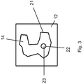
- FIG. 3 shows a plan view of a powder bed 12, wherein the melting and re-solidification of the powder material, a solid layer 14 has been created, which has a circumferential outer edge 21 and an inner edge 22 to delimit an inner cavity 23.
- the post-processing of the edge 21,22 of the solid state layer 14 takes place both along the outer edge and along the inner edge 21, which limits the cavity 23.
- the lifting table 2 with the component 3 arranged thereon is lowered again in the powder bed 12 (5th method step according to illustration 19) and according to method step 6 according to illustration 20 a new powder layer 5 applied with the slider 8, so that a new deposition of a solid layer 14 can begin with the method step 1 according to the representation 15.
- the process steps 1 to 6 can be performed repeatedly for depositing a plurality of solid state layers 14 until the component to be manufactured is finished.
- two different devices are provided, on the one hand, for cleaning the last deposited solid state layer and further parts of the already produced component 3 and, on the other hand, for applying a powder layer.
- the cleaning device or parts thereof and the device for applying a powder layer ie the brush 7 and the slide 8 can be integrated in a single device, so that a brush or a leveling and smoothing slide can be used both for applying a powder layer and for Cleaning the already manufactured component can be used before reworking the edge contour.
Abstract
Die vorliegende Erfindung betrifft ein Verfahren bzw. Vorrichtung zur generativen Herstellung von Bauteilen durch schichtweises Aufbringen von Pulvermaterial auf einem Substrat oder einem vorher hergestellten Teil eines Bauteils und zumindest teilweise stoffschlüssiges Verbinden des Pulvermaterials in der Pulverschicht entsprechend der Bauteilschnittkontur entlang der Pulverschicht und mit einem darunter liegenden Festkörpermaterial des Bauteils oder Substrats zur Ausbildung von mehreren übereinander angeordneten Festkörperschichten (14), wobei nach dem stoffschlüssigen Verbinden des Pulvermaterials die soeben erzeugte Festkörperschicht (14) von Pulvermaterial gereinigt und vor dem Abscheiden der nächsten Festkörperschicht der Rand (21,22) der Festkörperschicht durch Erweichen des Materialverbunds nachbearbeitet wird.The present invention relates to a method and apparatus for the generative production of components by layered application of powder material on a substrate or a previously prepared part of a component and at least partially cohesive bonding of the powder material in the powder layer corresponding to the component sectional contour along the powder layer and with an underlying Solid material of the component or substrate for forming a plurality of superposed solid layers (14), wherein after the material connection of the powder material, the just-generated solid layer (14) cleaned of powder material and before the deposition of the next solid layer of the edge (21,22) of the solid state layer Softening the composite material is reworked.
Description
Die vorliegende Erfindung betrifft ein Verfahren zur generativen Herstellung von Bauteilen durch schichtweises Aufbringen und stoffschlüssiges Verbinden von Pulvermaterial sowie eine Vorrichtung zur Durchführung eines entsprechenden Verfahrens.The present invention relates to a method for the generative production of components by layered application and cohesive bonding of powder material and an apparatus for performing a corresponding method.
Generative Herstellungsverfahren zur Herstellung eines Bauteils werden in der Industrie für das sogenannte Rapid - Tooling, Rapid - Pototyping oder bei der Herstellung von Serienprodukten im Rahmen des Rapid - Manufacturing eingesetzt. Beispiele für generative Herstellungsverfahren sind das selektive Laserschmelzen, das selektive Lasersintern, das Elektronenstrahlschmelzen und vergleichbare Verfahren.Generative manufacturing processes for the production of a component are used in the industry for so - called rapid - tooling, rapid - pototyping or in the production of series products within the scope of rapid manufacturing. Examples of additive manufacturing processes include selective laser melting, selective laser sintering, electron beam melting, and similar methods.
Bei diesen Verfahren wird das zu erzeugende Bauteil schichtweise aus Pulvermaterial aufgebaut, wobei das Pulvermaterial entsprechend der aufzubringenden Schicht in einer Pulverlage auf einem Substrat oder einem bereits hergestellten Teil eines Bauteils aufgebracht wird, um anschließend durch Aufschmelzen oder Sintern des Pulvers eine Verbindung des Pulvermaterials untereinander und zu dem Bauteil zu schaffen.In this method, the component to be produced is built up in layers of powder material, wherein the powder material is applied according to the applied layer in a powder layer on a substrate or an already manufactured part of a component to subsequently by melting or sintering of the powder, a compound of the powder material with each other and to create the component.
Um eine Pulverlage auf dem Bauteil zu erzeugen kann ein Pulverbett verwendet werden, in welchem der bereits erzeugte Teil des Bauteils angeordnet ist und in der Richtung des Aufbaus des Bauteils von einer Pulverlage überdeckt ist, die selektiv entsprechend der Kontur in der Schnittebene des zu erzeugenden Bauteils auf dem Bauteil abgeschieden werden soll. Die Oberfläche des Pulverbetts wird dabei so gewählt, dass zwischen dem bereits erzeugten Bauteil und der Oberfläche des Pulverbetts die Pulverlage mit der gewünschten Dicke vorliegt, die im nächsten Schritt als Festkörperschicht auf dem Bauteil durch Aufschmelzen oder Sintern und nachfolgende Wiedererstarren abgeschieden werden soll. Durch selektives Schmelzen oder Sintern entsprechend dem Schnittmuster des zu erzeugenden Bauteils in der jeweiligen Lage und nachfolgendes Erstarren können dreidimensionale Gegenstände erzeugt werden.In order to create a powder layer on the component, a powder bed may be used, in which the already produced part of the component is arranged and is covered in the direction of the construction of the component by a powder layer, which selectively according to the contour in the sectional plane of the component to be produced to be deposited on the component. The surface of the powder bed is chosen so that between the already produced component and the surface of the powder bed the powder layer is present with the desired thickness, which is to be deposited in the next step as a solid state layer on the component by melting or sintering and subsequent re-solidification. By selective melting or sintering according to the pattern of the component to be produced in the respective layer and subsequent solidification three-dimensional objects can be generated.
Aus dem Stand der Technik sind bereits entsprechende Vorrichtungen und Verfahren bekannt, wie sie unter anderem in der
Allerdings besteht bei generativ hergestellten Produkten das Problem, dass die erzeugten Oberflächen sehr rau sind und so einer Nachbearbeitung bedürfen, die unter Umständen sehr aufwändig sein kann. Darüber hinaus kann es bei der Ausbildung von Hohlräumen dazu kommen, dass eine Nachbearbeitung der rauen Oberflächen des Hohlraums überhaupt nicht mehr möglich ist, so dass es durch die rauen Oberflächen und die dort möglichen Spannungsspitzen bei mechanischer Belastung zu einer Beeinträchtigung der Festigkeitseigenschaften des hergestellten Bauteils kommen kann.However, there is the problem with generatively produced products that the surfaces produced are very rough and so require a rework, which can be very expensive under certain circumstances. In addition, in the formation of cavities may happen that a reworking of the rough surfaces of the cavity is no longer possible, so that it comes through the rough surfaces and the possible voltage peaks under mechanical stress to a deterioration of the strength properties of the manufactured component can.
Es ist deshalb Aufgabe der vorliegenden Erfindung ein Verfahren zu generativen Herstellung von Bauteilen bereitzustellen, bei welchem die Oberflächenrauheit des hergestellten Bauteils reduziert ist, so dass auf eine aufwändige Nachbearbeitung der Oberfläche verzichtet oder diese stark reduziert werden kann. Insbesondere soll somit ein Verfahren und eine entsprechende Vorrichtung zur Herstellung von generativ erzeugten Bauteilen bereitgestellt werden, die es ermöglichen, möglichst glatte Oberflächen bei den hergestellten Bauteilen zu erzeugen, wobei gleichwohl das Verfahren effizient und zuverlässig durchführbar sein soll und der Aufwand für eine entsprechende Vorrichtung gering gehalten werden soll.It is therefore an object of the present invention to provide a method for the additive production of components, in which the surface roughness of the manufactured component is reduced, so that an elaborate finishing of the surface can be dispensed with or it can be greatly reduced. In particular, a method and a corresponding device for the production of generatively produced components should thus be provided, which make it possible to produce as smooth as possible surfaces in the manufactured components, although the method should be efficient and reliable feasible and the cost of a corresponding device low should be kept.
Diese Aufgabe wird gelöst mit einem Verfahren zur generativen Herstellung von Bauteilen mit den Merkmalen des Anspruchs 1 sowie einer Vorrichtung mit den Merkmalen des Anspruchs 10. Vorteilhafte Ausgestaltungen sind Gegenstand der abhängigen Ansprüche. Die vorliegende Erfindung schlägt zur Verbesserung der Oberflächenqualität von generativ hergestellten Bauteilen vor, dass nach dem Abscheiden einer Festkörperschicht, also nach dem Aufbringen von Pulvermaterial und stoffschlüssigem Verbinden des Pulvermaterials an sich und mit einem darunter liegenden Material eines Substrats oder eines bereits hergestellten Bauteils, zumindest die zuletzt abgeschiedene Festkörperschicht vom Pulvermaterial gereinigt wird und der Rand der Festkörperschicht vor dem Abscheiden der nächsten Festkörperschicht durch Erweichen des Materials nachbearbeitet wird. Dadurch lässt sich eine Glättung des Randes der Festkörperschicht und somit der Oberfläche des generativ hergestellten Bauteils erzielen.This object is achieved with a method for the generative production of components with the features of
Insbesondere kann die Reinigung der Festkörperschicht von Pulvermaterial nach jeder Abscheidung einer Festkörperschicht erfolgen und entsprechend auch die Nachbearbeitung des Randes der abgeschieden Festkörperschicht zwischen jeweils zwei aufeinander folgenden Abscheidungen von Festkörperschichten durchgeführt werden.In particular, the cleaning of the solid state layer of powder material can be carried out after each deposition of a solid layer and, accordingly, the post-processing of the edge of the deposited solid layer between each two successive deposits of solid layers are performed.
Bei der Reinigung der zuletzt abgeschiedenen Festkörperschicht zur Entfernung von lose haftendem Pulvermaterial können zusätzlich weitere Bereiche des bereit hergestellten Bauteils, also insbesondere eine oder mehrere bereits zu einem früheren Zeitpunkt abgeschiedene Festkörperschichten, die vorzugsweise benachbart zur zuletzt abgeschiedenen Festkörperschicht liegen, ebenfalls von Pulvermaterial gereinigt werden, so dass bei der Erweichung des Randbereichs der abgeschiedenen Festkörperschicht nicht bereits durch eine Nachbearbeitung geglättete Oberflächen durch Anhaften von Pulverpartikeln wieder beeinträchtig werden.When cleaning the last deposited solid layer to remove loose-adhering powder material, additional areas of the ready-made component, ie in particular one or more already deposited at an earlier time solid state layers, which are preferably adjacent to the last deposited solid state layer can also be cleaned of powder material so that when softening the edge region of the deposited solid layer not smoothed by a post-processing surfaces are adversely affected by the adhesion of powder particles again.
Die Reinigung der Festkörperschicht und/oder weiterer benachbarter Teile des bereits erzeugten Bauteils kann durch eine Vielzahl von verschiedenen Reinigungsmethoden erfolgen, die eine geeignete Entfernung von losem Pulvermaterial ermöglichen. Insbesondere können mechanische Verfahren zur Entfernung des Pulvermaterials, wie Bürsten, Abstreifen, oder auch berührungslose Methoden zur Entfernung von Pulvermaterial eingesetzt werden, wie beispielsweise das Absaugen oder das Sprühen oder Spritzen mit einem Fluid, insbesondere mit Druckluft oder anderen Gasen. Darüber hinaus kann der Reinigungsschritt auch das Anheben des bereits hergestellten Bauteils aus einem umgebenden Pulverbett oder das Absenken eines umgebenden Pulverbetts umfassen. Der Reinigungsschritt oder Teile davon können bei der Durchführung des Verfahrens auch mehrmals hintereinander durchgeführt werden.The cleaning of the solid state layer and / or other adjacent parts of the already produced component can be done by a variety of different cleaning methods that allow a suitable removal of loose powder material. In particular, mechanical methods for removing the powder material, such as brushing, stripping, or non-contact methods for removing powder material can be used, such as the suction or spraying or spraying with a fluid, in particular with compressed air or other gases. In addition, the cleaning step may also include lifting the already manufactured component from a surrounding powder bed or lowering a surrounding powder bed. The cleaning step or parts thereof can also be carried out several times in succession when carrying out the method.
Das stoffschlüssige Verbinden des Pulvermaterials kann durch alle bekannten Verfahren für die generative Herstellung von Bauteilen durchgeführt werden, insbesondere durch selektives Bestrahlen mit einem hochenergetischen Strahl, wie z.B. durch selektives Laserstrahlschmelzen, selektives Laserstrahlsintern, selektives Elektronenstrahlschmelzen oder selektives Elektronenstrahlsintern.The cohesive bonding of the powder material can be carried out by any known method for the generative production of components, in particular by selective irradiation with a high-energy beam, such as e.g. by selective laser beam melting, selective laser beam sintering, selective electron beam melting, or selective electron beam sintering.
Die Nachbearbeitung des Randes der abgeschiedenen Festkörperschicht durch Erwärmen des Materials kann entsprechend dem Verfahren zum stoffschlüssigen Verbinden des Pulvermaterials ebenfalls durch einen hochenergetischen Strahl, insbesondere einen Elektronen - oder Laserstrahl vorgenommen werden, wobei bei der Nachbearbeitung mit einem hochenergetischen Strahl das Randmaterial der nachbearbeiteten Festkörperschicht durch Erwärmen erweicht wird und/oder aufgeschmolzen werden kann. Hierbei kann ein hochenergetischer Strahl eingesetzt werden, der von der gleichen oder einer separatent Strahlungsquelle erzeugt wird wie der hochenergetische Strahl zum stoffschlüssigen Verbinden des Pulvermaterials. Bei Verwendung der gleichen Strahlungsquelle können jedoch die Parameter bei der Erzeugung des hochenergetischen Strahls unterschiedlich gewählt werden. Zusätzlich oder alternativ ist es auch möglich den hochenergetischen Strahl nach der Erzeugung unterschiedlich zu beeinflussen bzw. zu formen, beispielsweise durch unterschiedliche Strahlaufweitung oder Fokussierung, um unterschiedliche Bearbeitungsbedingungen für das stoffschlüssige Verbinden und die Nachbearbeitung des stoffschlüssig verbundenen Materials einzustellen. Hierzu kann eine entsprechende Vorrichtung eine Strahlformungseinheit aufweisen.The post-processing of the edge of the deposited solid state layer by heating the material may also be effected by a high-energy beam, in particular an electron beam or laser beam, in accordance with the method for integrally bonding the powder material be made, wherein in the post-processing with a high-energy beam, the edge material of the post-processed solid state layer is softened by heating and / or can be melted. In this case, a high-energy beam can be used, which is generated by the same or a separate source of radiation as the high-energy beam for cohesive bonding of the powder material. When using the same radiation source, however, the parameters in the generation of the high-energy beam can be chosen differently. Additionally or alternatively, it is also possible to influence or shape the high-energy beam differently after the generation, for example by different beam expansion or focusing, in order to set different processing conditions for the integral connection and the post-processing of the materially bonded material. For this purpose, a corresponding device may have a beam shaping unit.
Die Nachbearbeitung des Randes der Festkörperschicht vor dem Abscheiden der nächsten Festkörperschicht kann ebenso wie die Reinigung mehrmals erfolgen kann, sodass also eine mehrmalige Erweichung und/oder Aufschmelzung des Randes der Festkörperschicht vorgenommen werden kann.The post-processing of the edge of the solid-state layer before the deposition of the next solid-state layer, as well as the cleaning can be done several times, so that a repeated softening and / or melting of the edge of the solid state layer can be made.
Die Nachbearbeitung des Randes der Festkörperschicht und insbesondere das Aufschmelzen und Wiedererstarren können insbesondere im Vergleich zur Abscheidung der Festkörperschicht langsam durchgeführt werden, um zur Glättung der Oberfläche des Bauteils ausreichend Zeit für die erforderlichen Prozesse zur Verfügung zu stellen.The post-processing of the edge of the solid-state layer and in particular the melting and re-solidification can be carried out slowly, in particular in comparison to the deposition of the solid state layer, in order to provide sufficient time for the required processes for smoothing the surface of the component.
Wird das Erwärmen des Randes der Festkörperschicht zum Erweichen und/oder Aufschmelzen des Randes der Festkörperschicht mit einem hochenergetischen Strahl durchgeführt, so kann der hochenergetische Strahl bei einer Leistung von 60 bis 90 %, insbesondere 70 bis 80 % der Leistung betrieben werden, die für die stoffschlüssige Verbindung des Pulvermaterials bei der Abscheidung der Festkörperschicht eingesetzt wird. Da bei einer Bearbeitung des Pulvermaterials zur stoffschlüssigen Verbindung bzw. bei einer Nachbearbeitung des Randes der Festkörperschicht der hochenergetische Strahl, beispielsweise ein Laser - oder Elektronenstrahl, relativ zum zu erzeugenden Bauteil bewegt wird, kann das Erwärmen zum Erweichen und/oder Aufschmelzen des Rands der Festkörperschicht bei einer Vorschubgeschwindigkeit des hochenergetischen Strahls relativ zum Bauteil durchgeführt werden, die 20 bis 50 %, insbesondere 30 bis 40 % der Vorschubgeschwindigkeit beträgt, die der hochenergetische Strahl bei der stoffschlüssigen Verbindung des Pulvermaterials bei der Abscheidung einer Festkörperschicht aufweist. Dadurch kann dem Material bei der Nachbearbeitung ausreichend Zeit für die Glättungsprozesse während des Erweichens und/oder Aufschmelzens des Randbereichs gegeben werden.If the heating of the edge of the solid-state layer for softening and / or melting the edge of the solid-state layer is carried out with a high-energy beam, the high-energy beam can be operated at a power of 60 to 90%, in particular 70 to 80% of the power required for the cohesive connection of the powder material is used in the deposition of the solid state layer. Since the high-energy beam, for example a laser beam or electron beam, is moved relative to the component to be produced during machining of the powder material for the material connection or when the edge of the solid state layer is being heated, heating may be used to soften and / or melt the edge of the solid layer be carried out at a feed rate of the high-energy beam relative to the component, which is 20 to 50%, in particular 30 to 40% of the feed rate, which has the high-energy beam in the material connection of the powder material in the deposition of a solid layer. Thereby In the case of post-processing, the material can be given sufficient time for the smoothing processes during the softening and / or melting of the edge region.
Eine erfindungsgemäße Vorrichtung weist zur Durchführung des erfindungsgemäßen Verfahrens somit mindestens eine Reinigungsvorrichtung auf, die geeignet ist, das bereits hergestellte Bauteil mit zuletzt abgeschiedenen Festkörperschicht von Pulvermaterial zu befreien, bevor die Nachbearbeitung des Randes der abgeschiedenen Schicht durchgeführt wird. Eine entsprechende Reinigungsvorrichtung kann somit Vorrichtungen zum Bürsten und/oder Abstreifen und/oder zum Absaugen und/oder Abblasen von Pulvermaterial aufweisen. Darüber hinaus ist die Vorrichtung so eingerichtet, dass während des Betriebs der Reinigungsvorrichtung, wenn also Pulvermaterial von der zuletzt abgeschiedenen Festkörperschicht und vorzugsweise von weiteren angrenzenden Bereichen des Bauteils entfernt wird, eine Bauteilaufnahme, auf der das herzustellende Bauteil angeordnet ist, aus einem umgebenen Pulverbett angehoben bzw. das Pulverbett relativ zur Bauteilaufnahme abgesenkt werden kann.A device according to the invention therefore has at least one cleaning device for carrying out the method according to the invention, which is suitable for freeing the already manufactured component with last-deposited solid layer of powder material before the post-processing of the edge of the deposited layer is carried out. A corresponding cleaning device can thus have devices for brushing and / or stripping and / or for sucking off and / or blowing off powder material. In addition, the device is set up such that during operation of the cleaning device, ie when powder material is removed from the last deposited solid layer and preferably from further adjacent regions of the component, a component receptacle on which the component to be manufactured is arranged is lifted from a surrounding powder bed or the powder bed can be lowered relative to the component holder.
Die beigefügten Zeichnungen zeigen in rein schematischer Weise in
- Fig. 1
- eine schematische Darstellung einer Ausführungsform einer erfindungsgemäßen Vorrichtung zur generativen Herstellung von Bauteilen am Beispiel des selektiven Laserschmelzens,
- Fig. 2
- eine Darstellung des Verfahrensablaufs gemäß einem Ausführungsbeispiel des erfindungsgemäßen Verfahrens und in
- Fig. 3
- eine Draufsicht auf ein Pulverbett und eine hergestellte Festkörperschicht.
- Fig. 1
- a schematic representation of an embodiment of an inventive device for the generative production of components using the example of selective laser melting,
- Fig. 2
- a representation of the process flow according to an embodiment of the method according to the invention and in
- Fig. 3
- a plan view of a powder bed and a prepared solid state layer.
Weitere Vorteile, Kennzeichen und Merkmale der vorliegenden Erfindung werden bei der nachfolgenden detaillierten Beschreibung von Ausführungsbeispielen deutlich, wobei die Erfindung nicht auf diese Ausführungsbeispiele beschränkt ist.Further advantages, characteristics and features of the present invention will become apparent in the following detailed description of embodiments, wherein the invention is not limited to these embodiments.
Die
Um unerwünschte Reaktionen mit der Umgebungsatmosphäre beim Aufschmelzen oder Sintern zu vermeiden, kann der Prozess in einem abgeschlossenen Raum, der durch ein Gehäuse 11 der Vorrichtung 1 bereit gestellt wird, stattfinden und es kann zudem eine inerte Gasatmosphäre bereit gestellt werden, um beispielsweise Oxidation des Pulvermaterials und dergleichen beim Abscheiden zu vermeiden. Als inertes Gas kann beispielsweise Stickstoff verwendet werden, welches über eine nicht dargestellte Gasversorgung bereitgestellt werden kann.In order to avoid unwanted reactions with the ambient atmosphere during melting or sintering, the process may take place in a closed space provided by a
Anstelle des Inertgases könnte auch ein anderes Prozessgas verwendet werden, wenn beispielsweise eine reaktive Abscheidung des Pulvermaterials gewünscht ist.Instead of the inert gas and another process gas could be used, for example, if a reactive deposition of the powder material is desired.
Darüber hinaus sind auch andere Strahlungsarten denkbar, wie beispielsweise Elektronenstrahlen oder andere Teilchenstrahlen oder Lichtstrahlen, die bei der Stereolithographie eingesetzt werden.In addition, other types of radiation are conceivable, such as electron beams or other particle beams or light beams, which are used in stereolithography.
Der Schieber 8 ist gleichzeitig als Nivellier- und Glättungsschieber ausgebildet, um die Pulverlage oberhalb des Halbzeugs 3 zu glätten und auf eine bestimmte Lagendicke einzustellen. Allerdings ist es auch vorstellbar, dass der Schieber 8 lediglich die grobe Bereitstellung des Pulvermaterials bewirkt und ein zusätzlicher (hier nicht gezeigt) Nivellier- und Glättungsschieber eingesetzt wird.The
Der Nivellier- und Glättungsschieber 8 dient dazu, die gewünschte Dicke D der Pulverlage 5, wie sie in der Detailansicht der
Die Vorrichtung 1 weist weiterhin eine Reinigungsvorrichtung in Form einer Bürste 7 auf, die zur Reinigung der zuletzt abgeschiedenen Festkörperschicht und des bereits hergestellten Bauteils 3 vor einer Nachbearbeitung des Rands der Festkörperschicht dient. Nachdem die Pulverlage 5 bzw. das darin vorliegende Pulvermaterial mit dem Laserstrahl 13 des Lasers 4 entsprechend der Form des herzustellenden Bauteils im Schnitt entlang der Pulverlage 5 aufgeschmolzen worden ist und nach dem Erstarren des aufgeschmolzenen Pulvermaterials zu einer Festkörperschicht 14 geworden ist (wie in den Darstellungen 15 und 16 in
Der Verfahrensablauf wird in der
Nachdem der Reinigungsschritt gemäß der Darstellung 17 abgeschlossen ist, wird entlang des Randes der Festkörperschicht 14 eine Nachbearbeitung durch erneutes Aufschmelzen des Randes mittels Laserstrahl 13 des Lasers 4 durchgeführt, so dass eine Glättung des Randbereichs und somit der Oberfläche des herzustellendes Bauteils 3 erreicht werden kann. Dies ist in
Nach der Nachbearbeitung des Randes 21,22 der zuletzt aufgebrachten Festkörperschicht 14 wird der Hubtisch 2 mit dem darauf angeordneten Bauteil 3 wieder im Pulverbett 12 abgesenkt (5. Verfahrensschritt gemäß der Darstellung 19) und es wird gemäß Verfahrensschritt 6 nach der Darstellung 20 eine neue Pulverlage 5 mit dem Schieber 8 aufgebracht, so dass eine erneute Abscheidung einer Festkörperschicht 14 mit dem Verfahrensschritt 1 gemäß der Darstellung 15 beginnen kann. Wie sich aus den Pfeilen zwischen den Darstellungen 15 bis 20 ergibt, können die Verfahrensschritte 1 bis 6 wiederholt zur Abscheidung einer Vielzahl von Festkörperschichten 14 durchgeführt werden, bis das herzustellende Bauteil fertig ist.After the reworking of the
In den gezeigten Ausführungsbeispielen sind zwei unterschiedliche Vorrichtungen zum einen zur Reinigung der zuletzt abgeschiedenen Festkörperschicht und weiteren Teilen des bereits hergestellten Bauteils 3 sowie zum anderen zur Aufbringungen einer Pulverlage vorgesehen. Allerdings können die Reinigungsvorrichtung bzw. Teile davon und die Vorrichtung zur Aufbringung einer Pulverlage, also die Bürste 7 und der Schieber 8, in einzigen Vorrichtung integriert sein, so dass eine Bürste bzw. ein Nivellierungs - und Glättungsschieber sowohl zur Aufbringung einer Pulverlage als auch zur Reinigung des bereits hergestellten Bauteils vor dem Nachbearbeiten der Randkontur eingesetzt werden kann.In the exemplary embodiments shown, two different devices are provided, on the one hand, for cleaning the last deposited solid state layer and further parts of the already produced
Obwohl die vorliegende Erfindung anhand der Ausführungsbeispiele detailliert beschrieben worden ist, ist für den Fachmann selbstverständlich, dass die Erfindung nicht auf diese Ausführungsbeispiele beschränkt ist, sondern dass vielmehr Änderungen in der Weise möglich sind, dass einzelne Merkmale weggelassen oder andersartige Kombinationen von Merkmalen verwirklicht werden können, solange der Schutzbereich der beigefügten Ansprüche nicht verlassen wird. Die vorliegende Offenbarung schließt sämtliche Kombinationen der vorgestellten Einzelmerkmale mit ein.Although the present invention has been described in detail with reference to the embodiments, it will be understood by those skilled in the art that the invention is not limited to these embodiments, but rather changes in the manner that individual features can be omitted or other combinations of features can be realized as long as the scope of protection of the appended claims is not abandoned. The present disclosure includes all combinations of the features presented.
- 11
- Vorrichtungcontraption
- 22
- HubtischLift table
- 33
- HalbzeugWorkpiece
- 44
- Laserlaser
- 55
- Pulverlagepowder layer
- 66
- PulverbettoberflächePowder bed surface
- 77
- Bürstebrush
- 88th
- Schieberpusher
- 99
- HubtischLift table
- 1010
- Pulverpowder
- 1111
- Gehäusecasing
- 1212
- Pulverbettpowder bed
- 1313
- Laserstrahllaser beam
- 1414
- FestkörperschichtSolid layer
- 1515
-
Verfahrensschritt 1
Process step 1 - 1616
-
Verfahrensschritt 2
Process step 2 - 1717
-
Verfahrensschritt 3
Process step 3 - 1818
-
Verfahrensschritt 4
Process step 4 - 1919
- Verfahrensschritt 5Process step 5
- 2020
-
Verfahrensschritt 6
Process step 6 - 2121
- Rand der FestkörperschichtEdge of the solid-state layer
- 2222
- Rand der FestkörperschichtEdge of the solid-state layer
- 2323
- Hohlraumcavity
Claims (13)
dadurch gekennzeichnet, dass
nach dem stoffschlüssigen Verbinden des Pulvermaterials die soeben erzeugte Festkörperschicht (14) von Pulvermaterial gereinigt und vor dem Abscheiden der nächsten Festkörperschicht der Rand (21,22) der Festkörperschicht durch Erwärmen des Materialverbunds nachbearbeitet wird.A method for the generative production of components by layered application of powder material on a substrate or a previously manufactured part of a component and at least partially cohesive bonding of the powder material in the powder layer corresponding to the component sectional contour along the powder layer and with an underlying solid material of the component or substrate for the formation of a plurality of superposed solid layers (14),
characterized in that
after the cohesive bonding of the powder material, the just-produced solid layer (14) is cleaned of powder material and, before the deposition of the next solid layer, the edge (21, 22) of the solid layer is finished by heating the composite material.
dadurch gekennzeichnet, dass
die Reinigung der Festkörperschicht (14) von Pulvermaterial nach jeder Abscheidung einer Festkörperschicht erfolgt.Method according to claim 1,
characterized in that
the cleaning of the solid state layer (14) of powder material takes place after each deposition of a solid layer.
dadurch gekennzeichnet, dass
die Reinigung der Festkörperschicht (14) die Entfernung von Pulvermaterial von einer oder mehreren vor der letzten aufgebrachten Festkörperschicht abgeschiedenen Festkörperschichten umfasst.Method according to one of the preceding claims,
characterized in that
cleaning the solid state layer (14) comprises removing powder material from one or more solid state layers deposited prior to the last solid state layer applied.
dadurch gekennzeichnet, dass
die Reinigung der Festkörperschicht (14) durch mindestens eine Methode aus der Gruppe erfolgt, die mechanisches Entfernen des Pulvermaterials, Bürsten, Abstreifen, Absaugen, Reinigen durch Sprühen oder Spritzen mit einem Fluid, Abblasen mit Druckluft oder anderen Gasen, Anheben aus einem umgebenden Pulverbett (12) und Absenken eines umgebenden Pulverbetts umfasst.Method according to one of the preceding claims,
characterized in that
the cleaning of the solid-state layer (14) by at least one method from the group, the mechanical removal of the powder material, brushing, stripping, suction, cleaning by spraying or spraying with a fluid, blowing off with compressed air or other gases, lifting from a surrounding powder bed ( 12) and lowering a surrounding powder bed.
dadurch gekennzeichnet, dass
das stoffschlüssige Verbinden des Pulvermaterials durch einen hochenergetischen Strahl,
insbesondere durch selektives Laserschmelzen oder - sintern oder durch selektives Elektronenstrahlschmelzen oder - sintern erfolgt.Method according to one of the preceding claims,
characterized in that
the cohesive bonding of the powder material by a high-energy jet,
in particular by selective laser melting or sintering or by selective electron beam melting or sintering.
dadurch gekennzeichnet, dass
die Nachbearbeitung des Rands (21,22) der Festkörperschicht vor der Abscheidung der nächsten Festkörperschicht mehrmals erfolgt.Method according to one of the preceding claims,
characterized in that
the post-processing of the edge (21, 22) of the solid-state layer takes place several times before the deposition of the next solid-state layer.
dadurch gekennzeichnet, dass
das Erwärmen des Rands (21,22) der Festkörperschicht zum Erweichen und/oder Aufschmelzen des Rands der Festkörperschicht führt und durch einen hochenergetischen Strahl, insbesondere durch Laser - oder Elektronenstrahlen erfolgt.Method according to one of the preceding claims,
characterized in that
the heating of the edge (21, 22) of the solid state layer leads to softening and / or melting of the edge of the solid state layer and is effected by a high - energy beam, in particular by laser or electron beams.
dadurch gekennzeichnet, dass
das Erweichen und/oder Aufschmelzen des Rands (21,22) der Festkörperschicht mit 60 bis 90 %, insbesondere 70 bis 80 % der Leistung des hochenergetischen Strahls erfolgt, mit der die stoffschlüssige Verbindung des Pulvermaterials bei der Abscheidung einer Festkörperschicht erfolgt.Method according to claim 7,
characterized in that
the softening and / or melting of the edge (21, 22) of the solid-state layer takes place with 60 to 90%, in particular 70 to 80%, of the power of the high-energy beam with which the cohesive connection of the powder material takes place during the deposition of a solid layer.
dadurch gekennzeichnet, dass
das Erweichen und/oder Aufschmelzen des Rands (21,22) der Festkörperschicht mit 20 bis 50 %, insbesondere 30 bis 40 % einer Vorschubgeschwindigkeit des hochenergetischen Strahls erfolgt, mit der der hochenergetische Strahl bei der stoffschlüssigen Verbindung des Pulvermaterials bei der Abscheidung einer Festkörperschicht bewegt wird.Method according to claim 7 or 8,
characterized in that
the softening and / or melting of the edge (21, 22) of the solid-state layer takes place with 20 to 50%, in particular 30 to 40%, of a feed rate of the high-energy jet with which the high-energy beam moves during the material connection of the powder material during the deposition of a solid layer becomes.
dadurch gekennzeichnet, dass
der hochenergetische Strahl für die Nachberarbeitung durch Erwärmen aus derselben Strahlquelle stammt wie der hochenergetische Strahl zum stoffschlüssigen Verbinden des Pulvermaterials, wobei insbesondere die Strahlen für die Nachbearbeitung und stoffschlüssige Verbindung unterschiedlich erzeugt und/oder unterschiedlich beeinflusst oder geformt werden.Method according to one of the preceding claims,
characterized in that
the high-energy beam for the post-processing by heating from the same beam source as the high-energy beam for cohesive bonding of the powder material, in particular the beams for the post-processing and cohesive connection generated differently and / or differently influenced or shaped.
dadurch gekennzeichnet, dass
die Vorrichtung eine Reinigungsvorrichtung (7) umfasst, mit der das teilweise hergestellte Bauteil (3) von Pulvermaterial gereinigt werden kann, wobei die Vorrichtung so hergerichtet ist, dass bei der Reinigung mit der Reinigungsvorrichtung die Bauteilaufnahme so gegenüber dem Pulverbett eingestellt ist, dass das zumindest teilweise hergestellte Bauteil zumindest teilweise aus dem Pulverbett hervorsteht.Apparatus for carrying out the method according to one of the preceding claims with a component receptacle (2) for receiving a substrate or already partially manufactured component and with a powder applicator with a powder bed (12), which surrounds the component or substrate in the component holder at least partially, wherein the powder applicator deposited as a layer powder layer can be applied to the substrate or the component and wherein the component receptacle relative to the surface the powder bed is adjustable,
characterized in that
the device comprises a cleaning device (7) with which the partially manufactured component (3) can be cleaned of powder material, wherein the device is prepared so that when cleaning with the cleaning device, the component receptacle is adjusted relative to the powder bed that at least partially produced component protrudes at least partially from the powder bed.
dadurch gekennzeichnet, dass
die Vorrichtung weiterhin eine oder mindestens zwei Strahlerzeugungseinrichtungen zur Erzeugung eine hochenergetischen Strahls zum stoffschlüssigen Verbinden des Pulvermaterials und zum Nachbearbeiten des stoffschlüssig verbundenen Pulvermaterials durch Erwärmen aufweist.Device according to claim 11,
characterized in that
the apparatus further comprises one or at least two beam-generating means for generating a high-energy beam for material-bonding connection of the powder material and for reworking the cohesively connected powder material by heating.
dadurch gekennzeichnet, dass
die Vorrichtung eine Strahlformungseinheit zum Beeinflussen oder Formen des hochenergetischen Strahls aufweist.Device according to claim 11 or 12,
characterized in that
the apparatus comprises a beam shaping unit for influencing or shaping the high-energy beam.
Applications Claiming Priority (1)
| Application Number | Priority Date | Filing Date | Title |
|---|---|---|---|
| DE102016121594.5A DE102016121594A1 (en) | 2016-11-10 | 2016-11-10 | METHOD FOR IMPROVING THE SURFACE QUALITY OF GENERATIVELY PRODUCED COMPONENTS |
Publications (2)
| Publication Number | Publication Date |
|---|---|
| EP3321011A1 true EP3321011A1 (en) | 2018-05-16 |
| EP3321011B1 EP3321011B1 (en) | 2024-04-24 |
Family
ID=60382022
Family Applications (1)
| Application Number | Title | Priority Date | Filing Date |
|---|---|---|---|
| EP17198712.6A Active EP3321011B1 (en) | 2016-11-10 | 2017-10-26 | Method for improving the surface quality of components made by additive manufacturing |
Country Status (4)
| Country | Link |
|---|---|
| US (1) | US11104068B2 (en) |
| EP (1) | EP3321011B1 (en) |
| DE (1) | DE102016121594A1 (en) |
| WO (1) | WO2018086644A1 (en) |
Cited By (2)
| Publication number | Priority date | Publication date | Assignee | Title |
|---|---|---|---|---|
| CN109249024A (en) * | 2018-10-25 | 2019-01-22 | 哈尔滨工程大学 | The method that precinct laser fusion increasing material manufacturing quickly prepares metallic composite molded part |
| CN109530696A (en) * | 2018-12-28 | 2019-03-29 | 天津镭明激光科技有限公司 | A kind of substrate melts manufacturing process as the selective laser of part a part |
Families Citing this family (3)
| Publication number | Priority date | Publication date | Assignee | Title |
|---|---|---|---|---|
| US20200016831A1 (en) * | 2018-07-16 | 2020-01-16 | The Boeing Company | Additive-manufacturing systems and methods |
| DE102019200795A1 (en) | 2019-01-23 | 2020-07-23 | Robert Bosch Gmbh | Surface detection method for laser beam melting |
| RU2759104C1 (en) * | 2021-02-10 | 2021-11-09 | Федеральное государственное бюджетное образовательное учреждение высшего образования «МИРЭА - Российский технологический университет» | Method for producing metal products from powder material by layer-layer laser synthesis method using deformation treatment |
Citations (2)
| Publication number | Priority date | Publication date | Assignee | Title |
|---|---|---|---|---|
| JP2002038201A (en) * | 2000-07-24 | 2002-02-06 | Matsushita Electric Works Ltd | Method and apparatus for producing three-dimensional shape molded article |
| EP2868422A1 (en) * | 2013-10-29 | 2015-05-06 | Siemens Aktiengesellschaft | Method for manufacturing a component and optical irradiation device |
Family Cites Families (62)
| Publication number | Priority date | Publication date | Assignee | Title |
|---|---|---|---|---|
| US5824256A (en) * | 1996-12-05 | 1998-10-20 | Fortiflex, Inc. | Method of molding a thermoplastic container |
| DE19909390C1 (en) * | 1999-03-04 | 2000-11-09 | Fraunhofer Ges Forschung | Laser powder deposition head, useful for tool or component coating or repair, rapid prototyping or rapid tooling processes, has a radially symmetrical flow calming channel arrangement between a swirl chamber and an annular outlet gap |
| WO2002044079A1 (en) * | 2000-11-29 | 2002-06-06 | Seiko Instruments Inc. | Method and apparatus for manufacturing ultra fine three-dimensional structure |
| ATE317758T1 (en) * | 2001-01-24 | 2006-03-15 | Novartis Pharma Gmbh | METHOD FOR PRODUCING LENSES |
| ITRE20010073A1 (en) * | 2001-07-05 | 2003-01-05 | Sacmi | METHOD FOR LOADING THE CERAMIC MOLDS FOR FORMING THE TILES, RELATED MEANS OF IMPLEMENTATION, AND TILES OBTAINED WITH THE SAID |
| ITRE20010072A1 (en) * | 2001-07-05 | 2003-01-05 | Sacmi | METHOD FOR LOADING THE CERAMIC MOLDS OF FORMING THE TILES, IMPLANT FOR ITS IMPLEMENTATION, AND TILES OBTAINED WITH DET |
| DE10201635A1 (en) * | 2002-01-17 | 2003-07-31 | Coronet Werke Gmbh | Method and device for producing bristles |
| US20040028769A1 (en) * | 2002-04-30 | 2004-02-12 | Kreager Andrew S. | Foam sandwich composite molding method and apparatus |
| GB0210780D0 (en) * | 2002-05-13 | 2002-06-19 | Hayes Jonathan | A method of processing a stack of coatings and apparatus for processing a stack of coatings |
| DE10236907A1 (en) * | 2002-08-12 | 2004-02-26 | Fockele, Matthias, Dr. | Apparatus for making moldings using computer assisted design techniques by fusing layers of e.g. ceramic powder has leveling plate which smoothes off new layers of powder and bends over fixed obstructions |
| EP1419836B2 (en) * | 2002-11-07 | 2011-10-19 | CL Schutzrechtsverwaltungs GmbH | Process for preparing a workpiece through powder melting |
| DE10251790A1 (en) * | 2002-11-07 | 2004-05-19 | Degussa Ag | Composition for fluidized bed-, rotational-, electrostatic-, tribo-, or minicoating in the preparation of cosmetics and paint, comprises polyamide, polyamide derivatives, and flow aid |
| JP3944846B2 (en) * | 2002-12-03 | 2007-07-18 | 富士フイルム株式会社 | Method and apparatus for forming resin film |
| DE10300959C5 (en) * | 2003-01-14 | 2013-10-02 | Cl Schutzrechtsverwaltungs Gmbh | Coater device for a building device for producing molded parts from building material |
| US7077334B2 (en) * | 2003-04-10 | 2006-07-18 | Massachusetts Institute Of Technology | Positive pressure drop-on-demand printing |
| US20050173380A1 (en) * | 2004-02-09 | 2005-08-11 | Carbone Frank L. | Directed energy net shape method and apparatus |
| US8119053B1 (en) * | 2004-03-18 | 2012-02-21 | 3D Systems, Inc. | Apparatus for three dimensional printing using imaged layers |
| DE102004020452A1 (en) * | 2004-04-27 | 2005-12-01 | Degussa Ag | Method for producing three-dimensional objects by means of electromagnetic radiation and applying an absorber by inkjet method |
| US20050263933A1 (en) * | 2004-05-28 | 2005-12-01 | 3D Systems, Inc. | Single side bi-directional feed for laser sintering |
| US8653409B1 (en) * | 2004-06-23 | 2014-02-18 | Board Of Governors For Higher Education, State Of Rhode Island And Providence Plantations | Selective surface smoothing using lasers |
| US7871551B2 (en) * | 2005-05-11 | 2011-01-18 | Arcam Ab | Systems, apparatus, and methods to feed and distribute powder used to produce three-dimensional objects |
| JP4744200B2 (en) * | 2005-06-20 | 2011-08-10 | シーメット株式会社 | Solid modeling object with smoothed modeling end face |
| US7744717B2 (en) * | 2006-07-17 | 2010-06-29 | E. I. Du Pont De Nemours And Company | Process for enhancing the resolution of a thermally transferred pattern |
| EP1882564B1 (en) * | 2006-07-26 | 2012-04-11 | Heidelberger Druckmaschinen AG | Sheet cutting and creasing press with adjustable cutting and creasing pressure |
| US7614866B2 (en) * | 2007-01-17 | 2009-11-10 | 3D Systems, Inc. | Solid imaging apparatus and method |
| US8784723B2 (en) * | 2007-04-01 | 2014-07-22 | Stratasys Ltd. | Method and system for three-dimensional fabrication |
| ES2963291T3 (en) * | 2007-04-26 | 2024-03-26 | Sublimity Therapeutics Ltd | Manufacturing of multiple mini capsules |
| US8568121B2 (en) * | 2007-11-27 | 2013-10-29 | University Of Southern California | Techniques for sensing material flow rate in automated extrusion |
| DE102008022946B4 (en) * | 2008-05-09 | 2014-02-13 | Fit Fruth Innovative Technologien Gmbh | Apparatus and method for applying powders or pastes |
| DE102010046468B4 (en) * | 2010-09-24 | 2016-04-07 | MTU Aero Engines AG | Generative manufacturing process and powder for this purpose |
| DE102011008809A1 (en) * | 2011-01-19 | 2012-07-19 | Mtu Aero Engines Gmbh | Generatively produced turbine blade and apparatus and method for their production |
| US9776376B2 (en) * | 2011-08-29 | 2017-10-03 | Impossible Objects, LLC | Methods and apparatus for three-dimensional printed composites based on flattened substrate sheets |
| WO2013033273A2 (en) * | 2011-08-29 | 2013-03-07 | Impossible Objects Llc | Methods and apparatus for 3d fabrication |
| US8488994B2 (en) * | 2011-09-23 | 2013-07-16 | Stratasys, Inc. | Electrophotography-based additive manufacturing system with transfer-medium service loops |
| KR101648442B1 (en) * | 2012-03-09 | 2016-08-16 | 파나소닉 아이피 매니지먼트 가부시키가이샤 | Method of manufacturing three-dimensional sculpture |
| DE102013004940A1 (en) * | 2012-10-15 | 2014-04-17 | Voxeljet Ag | Method and device for producing three-dimensional models with tempered printhead |
| JP6359643B2 (en) * | 2013-05-03 | 2018-07-18 | ユナイテッド テクノロジーズ コーポレイションUnited Technologies Corporation | Method for removing subsurface pores |
| US20160250809A1 (en) * | 2013-05-24 | 2016-09-01 | Looking Glass Hk Ltd. | Method for manufacturing a physical volumetric representation of a virtual three-dimensional object |
| US20150048209A1 (en) * | 2013-08-16 | 2015-02-19 | Robert Hoyt | Structures with Internal Microstructures to Provide Multifunctional Capabilities |
| WO2015055550A1 (en) * | 2013-10-17 | 2015-04-23 | Luxexcel Holding B.V. | Device for printing a three-dimensional structure |
| JP6967348B2 (en) * | 2013-10-17 | 2021-11-17 | エックスジェット・リミテッドXjet Ltd. | Tungsten-Carbide / Cobalt Ink Composition for 3D Inkjet Printing |
| EP3068622A4 (en) * | 2013-11-11 | 2017-06-21 | Imerys Talc America, Inc. | Compositions and methods for fused filament fabrication |
| DE102013223587A1 (en) | 2013-11-19 | 2015-06-03 | MTU Aero Engines AG | Leveling and smoothing gate for the generative production of components |
| RU2580145C2 (en) * | 2013-11-21 | 2016-04-10 | Юрий Александрович Чивель | Production of 3d articles with gradient of properties of powders and device to this end |
| DE102014200234B4 (en) * | 2013-12-09 | 2022-07-07 | Magna International Inc. | Tool for hot forming and method for its manufacture |
| US11602892B2 (en) * | 2013-12-23 | 2023-03-14 | 3D Systems, Inc. | Three dimensional printing materials, systems, and methods |
| US20150209910A1 (en) * | 2014-01-24 | 2015-07-30 | Lincoln Global, Inc. | Method And System For Additive Manufacturing Of Cooling Passages Using High Energy Source |
| CN103978307B (en) * | 2014-04-30 | 2015-08-05 | 中国科学院化学研究所 | A kind of macromolecular material Ultra-Violet Laser 3D Method of printing for accurate temperature controlling and device |
| WO2015196149A1 (en) * | 2014-06-20 | 2015-12-23 | Velo3D, Inc. | Apparatuses, systems and methods for three-dimensional printing |
| KR102359288B1 (en) * | 2014-08-20 | 2022-02-04 | 에체-따르 에세.아. | Method and system for additive manufacturing using a light beam |
| DE102014217858A1 (en) * | 2014-09-08 | 2016-03-31 | MTU Aero Engines AG | Surface smoothing of generatively manufactured components and correspondingly manufactured components of a turbomachine |
| JP2016074956A (en) * | 2014-10-08 | 2016-05-12 | セイコーエプソン株式会社 | Three-dimensional formation apparatus and three-dimensional formation method |
| US10293378B2 (en) * | 2015-02-06 | 2019-05-21 | United Technologies Corporation | Powder processing apparatus for classifying and degassing |
| DE102015204801A1 (en) * | 2015-03-17 | 2016-09-22 | MTU Aero Engines AG | Method for manufacturing a component |
| US20160318260A1 (en) * | 2015-04-30 | 2016-11-03 | Elwha Llc | Printing systems and related methods |
| US20160279735A1 (en) * | 2015-03-27 | 2016-09-29 | Arcam Ab | Method for additive manufacturing |
| US10442175B2 (en) * | 2015-04-28 | 2019-10-15 | Warsaw Orthopedic, Inc. | 3D printing devices and methods |
| US20160326613A1 (en) * | 2015-05-07 | 2016-11-10 | General Electric Company | Article and method for forming an article |
| US20180071986A1 (en) * | 2015-06-01 | 2018-03-15 | Velo3D, Inc. | Three-dimensional printing |
| GB201515390D0 (en) * | 2015-08-28 | 2015-10-14 | Materials Solutions Ltd | Additive manufacturing |
| EP3386662A4 (en) * | 2015-12-10 | 2019-11-13 | Velo3d Inc. | Skillful three-dimensional printing |
| DE102016203649A1 (en) * | 2016-03-07 | 2017-09-07 | MTU Aero Engines AG | Micro-forging in a generative manufacturing process |
-
2016
- 2016-11-10 DE DE102016121594.5A patent/DE102016121594A1/en active Pending
-
2017
- 2017-10-26 EP EP17198712.6A patent/EP3321011B1/en active Active
- 2017-11-03 US US15/802,567 patent/US11104068B2/en active Active
- 2017-11-07 WO PCT/DE2017/000372 patent/WO2018086644A1/en active Application Filing
Patent Citations (2)
| Publication number | Priority date | Publication date | Assignee | Title |
|---|---|---|---|---|
| JP2002038201A (en) * | 2000-07-24 | 2002-02-06 | Matsushita Electric Works Ltd | Method and apparatus for producing three-dimensional shape molded article |
| EP2868422A1 (en) * | 2013-10-29 | 2015-05-06 | Siemens Aktiengesellschaft | Method for manufacturing a component and optical irradiation device |
Cited By (3)
| Publication number | Priority date | Publication date | Assignee | Title |
|---|---|---|---|---|
| CN109249024A (en) * | 2018-10-25 | 2019-01-22 | 哈尔滨工程大学 | The method that precinct laser fusion increasing material manufacturing quickly prepares metallic composite molded part |
| CN109249024B (en) * | 2018-10-25 | 2020-12-04 | 哈尔滨工程大学 | Method for rapidly preparing metal composite material formed part by selective laser melting additive manufacturing |
| CN109530696A (en) * | 2018-12-28 | 2019-03-29 | 天津镭明激光科技有限公司 | A kind of substrate melts manufacturing process as the selective laser of part a part |
Also Published As
| Publication number | Publication date |
|---|---|
| EP3321011B1 (en) | 2024-04-24 |
| DE102016121594A1 (en) | 2018-05-17 |
| US11104068B2 (en) | 2021-08-31 |
| WO2018086644A1 (en) | 2018-05-17 |
| US20180126634A1 (en) | 2018-05-10 |
Similar Documents
| Publication | Publication Date | Title |
|---|---|---|
| EP3321011B1 (en) | Method for improving the surface quality of components made by additive manufacturing | |
| EP3216546A1 (en) | Micro-forging in a generative production method | |
| DE10058748C1 (en) | Method for producing a component and device for carrying out the method | |
| EP2384882A1 (en) | Method for generative creation of a three dimensional object with spatial elements and method for producing a corresponding data set | |
| EP1144146B1 (en) | Device for selective laser sintering for producing a moulded part | |
| WO2012152259A1 (en) | Method for the production, reparation or replacement of a component, including a compacting step using pressure | |
| EP3017895A1 (en) | Manufacture of a component through selective laser melting | |
| DE102016115674A1 (en) | Additive manufacturing | |
| EP2493650A2 (en) | Method and device for producing a component of a turbomachine | |
| DE102014012425A1 (en) | Method for producing a three-dimensional object | |
| EP1397222B1 (en) | Procedure for the production of a work piece with exact geometry . | |
| DE102016115676A1 (en) | Additive manufacturing | |
| DE102014108081A1 (en) | Device and method for the generative production of at least one component region of a component | |
| DE102016209618A1 (en) | Method and device for the additive production of at least one component region of a component | |
| DE102016225178A1 (en) | Layer construction device and layer construction method for the additive production of at least one component region of a component | |
| EP3381593B1 (en) | Method for selective beam-based melting or sintering | |
| DE102011089336A1 (en) | Producing component from powder for turbomachines made of nickel-based alloys, by partially processing powder to green body in which non-powder particles are connected to each other and/or to green body using high energy beam | |
| WO2017220058A1 (en) | Method for producing at least one hybrid component having additively manufactured sub-regions | |
| DE19952267C2 (en) | Process for producing a mold | |
| EP3175941B1 (en) | Method and apparatus for additive manufacture of at least one component area of a component | |
| WO2019120348A1 (en) | Method and device for cleaning partially produced components during generative production | |
| DE102010024226A1 (en) | Producing or repairing component, preferably components of turbomachine, comprises applying first material layer on base and solidifying, producing first component portion, and applying second material layer on produced component portion | |
| DE102021127824A1 (en) | Device and method for surface treatment | |
| DE102014207001A1 (en) | Method and device for improving the material quality in generative manufacturing processes | |
| DE102019116503A1 (en) | Method and device for manufacturing a multi-material workpiece |
Legal Events
| Date | Code | Title | Description |
|---|---|---|---|
| PUAI | Public reference made under article 153(3) epc to a published international application that has entered the european phase |
Free format text: ORIGINAL CODE: 0009012 |
|
| STAA | Information on the status of an ep patent application or granted ep patent |
Free format text: STATUS: THE APPLICATION HAS BEEN PUBLISHED |
|
| AK | Designated contracting states |
Kind code of ref document: A1 Designated state(s): AL AT BE BG CH CY CZ DE DK EE ES FI FR GB GR HR HU IE IS IT LI LT LU LV MC MK MT NL NO PL PT RO RS SE SI SK SM TR |
|
| AX | Request for extension of the european patent |
Extension state: BA ME |
|
| STAA | Information on the status of an ep patent application or granted ep patent |
Free format text: STATUS: REQUEST FOR EXAMINATION WAS MADE |
|
| 17P | Request for examination filed |
Effective date: 20180704 |
|
| RBV | Designated contracting states (corrected) |
Designated state(s): AL AT BE BG CH CY CZ DE DK EE ES FI FR GB GR HR HU IE IS IT LI LT LU LV MC MK MT NL NO PL PT RO RS SE SI SK SM TR |
|
| STAA | Information on the status of an ep patent application or granted ep patent |
Free format text: STATUS: EXAMINATION IS IN PROGRESS |
|
| 17Q | First examination report despatched |
Effective date: 20181203 |
|
| STAA | Information on the status of an ep patent application or granted ep patent |
Free format text: STATUS: EXAMINATION IS IN PROGRESS |
|
| STAA | Information on the status of an ep patent application or granted ep patent |
Free format text: STATUS: EXAMINATION IS IN PROGRESS |
|
| RAP3 | Party data changed (applicant data changed or rights of an application transferred) |
Owner name: FRAUNHOFER-GESELLSCHAFT ZUR FOERDERUNG DER ANGEWANDTEN FORSCHUNG E.V. Owner name: MTU AERO ENGINES AG |
|
| RAP1 | Party data changed (applicant data changed or rights of an application transferred) |
Owner name: FRAUNHOFER-GESELLSCHAFT ZUR FOERDERUNG DER ANGEWANDTEN FORSCHUNG E.V. |
|
| REG | Reference to a national code |
Ref country code: DE Ref legal event code: R079 Free format text: PREVIOUS MAIN CLASS: B22F0003105000 Ipc: B22F0010500000 Ref country code: DE Ref legal event code: R079 Ref document number: 502017016056 Country of ref document: DE Free format text: PREVIOUS MAIN CLASS: B22F0003105000 Ipc: B22F0010500000 |
|
| RIC1 | Information provided on ipc code assigned before grant |
Ipc: B22F 3/24 20060101ALN20231004BHEP Ipc: B29C 64/35 20170101ALN20231004BHEP Ipc: B33Y 40/00 20150101ALN20231004BHEP Ipc: B22F 12/00 20210101ALN20231004BHEP Ipc: B29C 64/153 20170101ALI20231004BHEP Ipc: B33Y 30/00 20150101ALI20231004BHEP Ipc: B33Y 10/00 20150101ALI20231004BHEP Ipc: B22F 12/45 20210101ALI20231004BHEP Ipc: B22F 10/68 20210101ALI20231004BHEP Ipc: B22F 10/364 20210101ALI20231004BHEP Ipc: B22F 10/28 20210101ALI20231004BHEP Ipc: B22F 10/50 20210101AFI20231004BHEP |
|
| GRAP | Despatch of communication of intention to grant a patent |
Free format text: ORIGINAL CODE: EPIDOSNIGR1 |
|
| STAA | Information on the status of an ep patent application or granted ep patent |
Free format text: STATUS: GRANT OF PATENT IS INTENDED |
|
| INTG | Intention to grant announced |
Effective date: 20231115 |
|
| GRAS | Grant fee paid |
Free format text: ORIGINAL CODE: EPIDOSNIGR3 |
|
| GRAA | (expected) grant |
Free format text: ORIGINAL CODE: 0009210 |
|
| STAA | Information on the status of an ep patent application or granted ep patent |
Free format text: STATUS: THE PATENT HAS BEEN GRANTED |