EP3320987A1 - Vibration device - Google Patents
Vibration device Download PDFInfo
- Publication number
- EP3320987A1 EP3320987A1 EP17743969.2A EP17743969A EP3320987A1 EP 3320987 A1 EP3320987 A1 EP 3320987A1 EP 17743969 A EP17743969 A EP 17743969A EP 3320987 A1 EP3320987 A1 EP 3320987A1
- Authority
- EP
- European Patent Office
- Prior art keywords
- elastic plate
- section
- vibration device
- end portion
- joining
- Prior art date
- Legal status (The legal status is an assumption and is not a legal conclusion. Google has not performed a legal analysis and makes no representation as to the accuracy of the status listed.)
- Granted
Links
Images




Classifications
-
- B—PERFORMING OPERATIONS; TRANSPORTING
- B06—GENERATING OR TRANSMITTING MECHANICAL VIBRATIONS IN GENERAL
- B06B—METHODS OR APPARATUS FOR GENERATING OR TRANSMITTING MECHANICAL VIBRATIONS OF INFRASONIC, SONIC, OR ULTRASONIC FREQUENCY, e.g. FOR PERFORMING MECHANICAL WORK IN GENERAL
- B06B1/00—Methods or apparatus for generating mechanical vibrations of infrasonic, sonic, or ultrasonic frequency
- B06B1/02—Methods or apparatus for generating mechanical vibrations of infrasonic, sonic, or ultrasonic frequency making use of electrical energy
- B06B1/06—Methods or apparatus for generating mechanical vibrations of infrasonic, sonic, or ultrasonic frequency making use of electrical energy operating with piezoelectric effect or with electrostriction
- B06B1/0603—Methods or apparatus for generating mechanical vibrations of infrasonic, sonic, or ultrasonic frequency making use of electrical energy operating with piezoelectric effect or with electrostriction using a piezoelectric bender, e.g. bimorph
-
- H—ELECTRICITY
- H03—ELECTRONIC CIRCUITRY
- H03H—IMPEDANCE NETWORKS, e.g. RESONANT CIRCUITS; RESONATORS
- H03H9/00—Networks comprising electromechanical or electro-acoustic elements; Electromechanical resonators
- H03H9/02—Details
- H03H9/05—Holders or supports
- H03H9/09—Elastic or damping supports
-
- B—PERFORMING OPERATIONS; TRANSPORTING
- B06—GENERATING OR TRANSMITTING MECHANICAL VIBRATIONS IN GENERAL
- B06B—METHODS OR APPARATUS FOR GENERATING OR TRANSMITTING MECHANICAL VIBRATIONS OF INFRASONIC, SONIC, OR ULTRASONIC FREQUENCY, e.g. FOR PERFORMING MECHANICAL WORK IN GENERAL
- B06B1/00—Methods or apparatus for generating mechanical vibrations of infrasonic, sonic, or ultrasonic frequency
- B06B1/02—Methods or apparatus for generating mechanical vibrations of infrasonic, sonic, or ultrasonic frequency making use of electrical energy
- B06B1/06—Methods or apparatus for generating mechanical vibrations of infrasonic, sonic, or ultrasonic frequency making use of electrical energy operating with piezoelectric effect or with electrostriction
- B06B1/0644—Methods or apparatus for generating mechanical vibrations of infrasonic, sonic, or ultrasonic frequency making use of electrical energy operating with piezoelectric effect or with electrostriction using a single piezoelectric element
- B06B1/0662—Methods or apparatus for generating mechanical vibrations of infrasonic, sonic, or ultrasonic frequency making use of electrical energy operating with piezoelectric effect or with electrostriction using a single piezoelectric element with an electrode on the sensitive surface
- B06B1/0666—Methods or apparatus for generating mechanical vibrations of infrasonic, sonic, or ultrasonic frequency making use of electrical energy operating with piezoelectric effect or with electrostriction using a single piezoelectric element with an electrode on the sensitive surface used as a diaphragm
-
- H—ELECTRICITY
- H03—ELECTRONIC CIRCUITRY
- H03H—IMPEDANCE NETWORKS, e.g. RESONANT CIRCUITS; RESONATORS
- H03H9/00—Networks comprising electromechanical or electro-acoustic elements; Electromechanical resonators
- H03H9/02—Details
- H03H9/05—Holders or supports
- H03H9/10—Mounting in enclosures
-
- H—ELECTRICITY
- H03—ELECTRONIC CIRCUITRY
- H03H—IMPEDANCE NETWORKS, e.g. RESONANT CIRCUITS; RESONATORS
- H03H9/00—Networks comprising electromechanical or electro-acoustic elements; Electromechanical resonators
- H03H9/02—Details
- H03H9/125—Driving means, e.g. electrodes, coils
- H03H9/13—Driving means, e.g. electrodes, coils for networks consisting of piezoelectric or electrostrictive materials
-
- H—ELECTRICITY
- H03—ELECTRONIC CIRCUITRY
- H03H—IMPEDANCE NETWORKS, e.g. RESONANT CIRCUITS; RESONATORS
- H03H9/00—Networks comprising electromechanical or electro-acoustic elements; Electromechanical resonators
- H03H9/15—Constructional features of resonators consisting of piezoelectric or electrostrictive material
- H03H9/17—Constructional features of resonators consisting of piezoelectric or electrostrictive material having a single resonator
- H03H9/176—Constructional features of resonators consisting of piezoelectric or electrostrictive material having a single resonator consisting of ceramic material
-
- H—ELECTRICITY
- H10—SEMICONDUCTOR DEVICES; ELECTRIC SOLID-STATE DEVICES NOT OTHERWISE PROVIDED FOR
- H10N—ELECTRIC SOLID-STATE DEVICES NOT OTHERWISE PROVIDED FOR
- H10N30/00—Piezoelectric or electrostrictive devices
- H10N30/20—Piezoelectric or electrostrictive devices with electrical input and mechanical output, e.g. functioning as actuators or vibrators
- H10N30/204—Piezoelectric or electrostrictive devices with electrical input and mechanical output, e.g. functioning as actuators or vibrators using bending displacement, e.g. unimorph, bimorph or multimorph cantilever or membrane benders
- H10N30/2041—Beam type
- H10N30/2042—Cantilevers, i.e. having one fixed end
-
- H—ELECTRICITY
- H10—SEMICONDUCTOR DEVICES; ELECTRIC SOLID-STATE DEVICES NOT OTHERWISE PROVIDED FOR
- H10N—ELECTRIC SOLID-STATE DEVICES NOT OTHERWISE PROVIDED FOR
- H10N30/00—Piezoelectric or electrostrictive devices
- H10N30/80—Constructional details
- H10N30/85—Piezoelectric or electrostrictive active materials
- H10N30/853—Ceramic compositions
- H10N30/8548—Lead-based oxides
- H10N30/8554—Lead-zirconium titanate [PZT] based
Definitions
- the present invention relates to a vibration device in which a piezoelectric vibrating element is fixed to an elastic plate such as a metal plate.
- Patent Literature 1 described blow discloses an example of such a vibration device.
- the vibration device described in Patent Literature 1 includes an elastic plate obtained by bending a metal plate to have a U shape when viewed from a side.
- One side of the elastic plate is formed as a tabular fixed section and the other side of the elastic plate is formed as a tabular vibrating section with a bent section therebetween.
- a piezoelectric vibrating plate is provided in the vibrating section.
- Patent Literature 1 WO 2010/023801
- the vibration device of this type a further reduction in size and thickness is demanded according to a reduction in the sizes of mounted components resulting from a reduction in the sizes and improvement of the functions of electronic devices and the like.
- the strength of vibration tends to be low according to the reduction in the size and the thickness of the vibration device.
- An object of the present invention is to provide a vibration device in which a decrease in the strength of vibration involved in a reduction in thickness and size less easily occurs.
- a vibration device includes: a first elastic plate including first and second end portions and a first planar section located between the first and second end portions; a second elastic plate joined to the second end portion side of the first elastic plate, including a second planar section opposed to the first planar section of the first elastic plate, and having flexural rigidity higher than flexural rigidity of the first elastic plate; a piezoelectric vibrating element provided on a surface on a second elastic plate side in the first planar section of the first elastic plate; and a mass adding member attached to the first end portion of the first elastic plate.
- the vibration device further includes a package member provided to house the first elastic plate to which the piezoelectric vibrating element and the mass adding member are attached. In this case, it is possible to increase the strength of the vibration device.
- the vibration device further includes a circuit section provided on a surface on a first elastic plate side in the second planar section of the second elastic plate and forming at least a part of a circuit for driving the piezoelectric vibrating element.
- thickness of the second elastic plate is larger than thickness of the first elastic plate. In this case, it is possible effectively increase the flexural rigidity of the second elastic plate.
- a material of the second elastic plate has flexural rigidity higher than flexural rigidity of a material of the first elastic plate. In this case, it is possible to effectively increase the flexural rigidity of the second elastic plate.
- the first elastic plate includes a first joining section joined to the second elastic plate and a first linking section that links the first joining section and the first planar section, the first joining section is located further on the second end portion side than the first linking section, and the first elastic plate is bent to the second elastic plate side in the first linking section.
- the first joining section extends from the first linking section in a direction away from the first end portion, and the first joining section includes a surface extending in parallel to the second planar section of the second elastic plate and is joined to the second elastic plate on the surface. In this case, it is possible to promote a reduction in size.
- the first joining section extends from the first linking section in a direction approaching the first end portion, and the first joining section includes a surface extending in parallel to the second planar section of the second elastic plate and is joined to the second elastic plate on the surface.
- the second elastic plate includes third and fourth end portions, a second joining section in which the second elastic plate is joined to the first elastic plate, and a second linking section that links the second joining section and the second planar section, the second planar section is located between the third and fourth end portions, the second joining section is located further on a fourth end portion side than the second linking section, and the second elastic plate is bent to the first elastic plate side in the second linking section.
- the second joining section extends from the second linking section in a direction away from the third end portion, and the second joining section includes a surface extending in parallel to the first planar section of the first elastic plate and is joined to the first elastic plate on the surface.
- the second joining section includes the fourth end portion, the fourth end portion includes an end face of the second elastic plate, and the second joining section is joined to the first elastic plate on the end face.
- the second joining section is joined to the first elastic plate on the end face.
- the second elastic plate includes third and fourth end portions and a projecting section projecting to the first elastic plate side on the fourth end portion side, and the projecting section is jointed to the first elastic plate.
- the second elastic plate it is possible to increase an area of contact of the second elastic plate with a target on which the vibration device is mounted. Therefore, it is possible to efficiently propagate vibration to the outside.
- thickness of the projecting section is the same as thickness of at least a part of other than the projecting section in the second elastic plate, and a portion where the projecting section is formed is a concave section opened to a surface on an opposite side of the first elastic plate side of the second elastic plate.
- the projecting section includes the fourth end portion of the second elastic plate. In this case, it is possible to promote a reduction in the size of the vibration device.
- thickness of the second planar section of the second elastic plate is smaller than thickness of a portion where the second elastic plate is jointed to the first elastic plate.
- the mass adding member much less easily collides with the second elastic plate. Therefore, a decrease in the strength of vibration involved in a reduction in thickness and size much less easily occurs.
- the second elastic plate includes third and fourth end portions, and a portion where the first elastic plate and the second elastic plate are joined includes at least one of the second end portion of the first elastic plate and the fourth end portion of the second elastic plate. In this case, it is possible to promote a reduction in the size of the vibration device.
- a direction connecting the first and second end portions of the first elastic plate is a longitudinal direction of the first elastic plate.
- the first and second elastic plates are made of metal. In this case, it is possible to prevent a decrease in the strength of vibration in the first and second elastic plates.
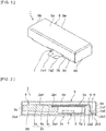
- Figure 1 is a perspective view showing the exterior of a vibration device according to a first embodiment of the present invention.
- Figure 2 is a side sectional view of the vibration device according to the first embodiment.
- Figure 3 is an exploded perspective view of the vibration device according to the first embodiment.
- a vibration device 1 shown in Figure 1 to Figure 3 can be used for, for example, a vibration notifying function of a portable electronic device.
- the vibration device 1 includes a first elastic plate 2a.
- the first elastic plate 2a includes first and second end portions 2a4 and 2a5.
- a direction connecting the first end portion 2a4 and the second end portion 2a5 is a longitudinal direction of the first elastic plate 2a.
- the vibration device 1 includes a second elastic plate 2b connected to the second end portion 2a5 side of the first elastic plate 2a.
- the second elastic plate 2b includes third and fourth end portions 2b4 and 2b5.
- the second elastic plate 2b includes a second joining section 2b3 located on the fourth end portion 2b5 side.
- the second elastic plate 2b is connected to the first elastic plate 2a in the second joining section 2b3.
- a direction connecting the third end portion 2b4 and the fourth end portion 2b5 is a longitudinal direction of the second elastic plate 2b. Note that the longitudinal directions in the first and second elastic plates 2a and 2b are not limited to the above description.
- the thickness of the second elastic plate 2b is larger than the thickness of the first elastic plate 2a. Further, the material of the second elastic plate 2b has flexural rigidity higher than the flexural rigidity of the material of the first elastic plate 2a. Consequently, the second elastic plate 2b has flexural rigidity higher than the flexural rigidity of the first elastic plate 2a.
- the flexural rigidity refers to a characteristic indicating difficulty of flexural deformation of an object at the time when force is applied to the object. High flexural rigidity means that the object is less easily flexurally deformed.
- the first elastic plate 2a is made of SUS304 and the second elastic plate 2b is made of SUS301.
- the first and second elastic plates 2a and 2b may be made of another material having elasticity such as metal other than the above or synthetic resin.
- the first and second elastic plates 2a and 2b are desirably made of metal such as stainless steel. Consequently, it is possible to further prevent a decrease in the strength of vibration in the first and second elastic plates 2a and 2b.
- first and second elastic plates 2a and 2b may be made of the same material. In this case, it is possible to set the flexural rigidity of the second elastic plate 2b higher than the elastic rigidity of the first elastic plate 2a by differentiating thicknesses or the like. Alternatively, the thicknesses of the first and second elastic plates 2a and 2b may be the same. In this case, it is possible to set the flexural rigidity of the second elastic plate 2b higher than the flexural rigidity of the first elastic plate 2a by using different materials or the like.
- the first elastic plate 2a includes a first planar section 2a1, a first linking section 2a2, and a first joining section 2a3 located between the first and second end portions 2a4 and 2a5.
- the first planar section 2a1 has a plane shape.
- the distal end portion of the first planar section 2a1 is located at the first end portion 2a4.
- the first linking section 2a2 connects the first planar section 2a1 and the first joining section 2a3.
- the first joining section 2a3 is joined to the second elastic plate 2b.
- the distal end portion of the first joining section 2a3 is located at the second end portion 2a5.
- the second elastic plate 2b includes a second planar section 2b1 and the second joining section 2b3 located between the third and fourth end portions 2b4 and 2b5.
- the second planar section 2b1 has a plane shape.
- the second planar section 2b1 of the second elastic plate 2b is opposed to the first planar section 2a1 of the first elastic plate 2a.
- the second joining section 2b3 is joined to the first joining section 2a3 of the first elastic plate 2a.
- the first elastic plate 2a is bent to the second elastic plate 2b side in the first linking section 2a2.
- the first joining section 2a3 extends from the first linking section 2a2 in a direction away from the first end portion 2a4.
- the first joining section 2a3 includes a surface extending in parallel to the second planar section 2b1 of the second elastic plate 2b.
- the first joining section 2a3 is joined to the second elastic plate 2b on the surface.
- the first elastic plate 2a and the second elastic plate 2b are desirably joined by welding. Consequently, it is possible to effectively increase joining strength.
- the welding can be performed by, for example, irradiation of laser light.
- the joining of the first and second elastic plates 2a and 2b is not limited to the above description.
- the joining may be achieved by, for example, a brazing metal or an adhesive.
- the first linking section 2a2 is located between an alternate long and short dash line A and an alternate long and short dash line B. Both end portions of the first linking section 2a2 are bent. Note that at least one of both the end portions of the first linking section 2a2 may be bent to have a corner portion.
- a piezoelectric vibrating element 3 is provided in the first planar section 2a1 of the first elastic plate 2a. More specifically, the piezoelectric vibrating element 3 is provided on a surface on the second elastic plate 2b side in the first planar section 2a1. The piezoelectric vibrating element 3 is fixed to the first elastic plate 2a using an appropriate adhesive such as a thermosetting resin adhesive.
- the piezoelectric vibrating element 3 has a rectangular tabular shape.
- Figure 4(a) is a side view of the piezoelectric vibrating element in the first embodiment.
- Figure 4(b) is a plan view of the piezoelectric vibrating element in the first embodiment.
- the piezoelectric vibrating element 3 includes a piezoelectric layer 4.
- the piezoelectric layer 4 includes a first principal plane 4a and a second principal plane 4b opposed to the first principal plane 4a.
- the piezoelectric vibrating element 3 is fixed to the first elastic plate from the first principal plane 4a side.
- a first electrode 5a and a second electrode 5b are provided on the second principal plane 4b of the piezoelectric layer 4.
- a third electrode 5c is provided on the first principal plane 4a to be opposed to the first electrode 5a with the piezoelectric layer 4 interposed therebetween.
- the third electrode 5c is electrically connected to the second electrode 5b by a via hole electrode or by a connection electrode (not shown in the figure) through a side surface of the piezoelectric layer 4.
- the piezoelectric layer 4 As a material configuring the piezoelectric layer 4, appropriate piezoelectric ceramics such as PZT ceramics can be used.
- the first to third electrodes 5a to 5c are made of appropriate metal or alloy.
- the configuration of the piezoelectric vibrating element 3 is not particularly limited.
- the piezoelectric vibrating element 3 expands and contracts in the in-plane direction.
- a warp occurs in the first elastic plate 2a shown in Figure 2 .
- the first elastic plate 2a repeats a state in which the first end portion 2a4 is displaced downward in Figure 2 and a state in which the first end portion 2a4 is displaced upward and vibrates.
- the vibration of the first elastic plate 2a is propagated to the second elastic plate 2b via the first joining section 2a3.
- the vibration device 1 is mounted from the second elastic plate 2b side. Vibration of the vibration device 1 is propagated from the second elastic plate 2b to the outside. Consequently, the vibration notifying function and the like are achieved.
- a characteristic of this embodiment resides in that the vibration device 1 includes the first elastic plate 2a on which the piezoelectric vibrating element 3 is provided and the second elastic plate 2b joined to the first elastic plate 2a and the second elastic plate 2b has the flexural rigidity higher than the flexural rigidity of the first elastic plate 2a. Consequently, a decrease in the strength of vibration of the second elastic plate 2b involved in a reduction in the thickness and the size of the vibration device 1 less easily occurs. Therefore, it is possible to efficiently propagate the vibration from the second elastic plate 2b to the outside. Details are explained below.
- a circuit board 6 functioning as a circuit section is provided in the second planar section 2b1 of the second elastic plate 2b. More specifically, the circuit board 6 is provided on a surface on the first elastic plate 2a side in the second planar section 2b1.
- circuit board 6 a glass epoxy board or an appropriate board material made of synthetic resin such as polyimide can be used. At least a part of a driving circuit for feeding electric power to the piezoelectric vibrating element 3 and driving the piezoelectric vibrating element 3 is formed on the circuit board 6.
- the circuit board 6 is electrically connected to the piezoelectric vibrating element 3 by a flexible printed wiring board 7.
- the flexible printed wiring board 7 is configured using a resin film having flexibility such as thermosetting polyimide.
- a conductive adhesive, solder, and the like can be used for connection of the circuit board 6 and the piezoelectric vibrating element 3 to the flexible printed wiring board 7.
- Figure 5 is a plan view showing, in an exploded state, the piezoelectric vibrating element, the circuit board, and the flexible printed wiring board for explaining a state of connection of the piezoelectric vibrating element and the circuit board in the first embodiment.
- the flexible printed wiring board 7 includes first electric connecting sections 7a1 and 7a2, a second electric connecting section 7b, third electric connecting sections 7c1 and 7c2, and a wire linking section 7d.
- the first electric connecting sections 7a1 and 7a2 are connected to the outside.
- the first electric connecting section 7a1 and the first electric connecting section 7a2 are connected to different potentials.
- the first electric connecting sections 7a1 and 7a2 are electrically connected to the second electric connecting section 7b by wires 7e1 and 7e2.
- the circuit board 6 is placed on the second electric connecting section 7b.
- the second electric connecting section 7b and the circuit board 6 are electrically connected.
- the second electric connecting section 7b is electrically connected to the third electric connecting sections 7c1 and 7c2 by wires 7e3 and 7e4 that pass through the wire linking section 7d.
- the third electric connecting sections 7c1 and 7c2 are connected to the piezoelectric vibrating element 3. More specifically, the third electric connecting section 7c1 is connected to the first electrode 5a of the piezoelectric vibrating element 3. The third electric connecting section 7c2 is connected to the second electrode 5b of the piezoelectric vibrating element 3.
- the flexible printed wiring board 7 is fixed to a surface on the first elastic plate 2a side in the second planar section 2b1 of the second elastic plate 2b.
- the fixing can be performed using an appropriate adhesive or an appropriate adhesive sheet.
- the wire linking section 7d is bent such that the second electric connecting section is disposed on the second elastic plate 2b and the third electric connecting section is disposed on the first elastic plate 2a.
- circuit section is not limited to the circuit board.
- the circuit section only has to form at least a part of a circuit for driving the piezoelectric vibrating element 3.
- the circuit section may be formed by a wiring element.
- the configuration of connection of the circuit section and the piezoelectric vibrating element 3 is not particularly limited either.
- the circuit section and the piezoelectric vibrating element 3 may be connected by a lead wire or the like.
- the first electric connecting sections 7a1 and 7a2 of the flexible printed wiring board 7 further protrude sideward than the second elastic plate 2b and a package member 9 explained below. Therefore, it is possible to easily perform electric connection to the outside.
- a mass adding member 8 is attached to the first end portion 2a4 of the first elastic plate 2a.
- a resonance frequency of the vibration device 1 can be adjusted by the mass adding member 8.
- the mass adding member 8 is made of appropriate metal, a combined material of metal and resin, ceramics, or the like. It is desirable that the mass adding member 8 is made of metal having high density such as tungsten because mass adding action is high.
- the mass adding member 8 includes a first principal plane 8A located on the first elastic plate 2a side and a second principal plane 8B located on the second elastic plate 2b side.
- the first principal plane 8A of the mass adding member 8 has a step-wise shape. More specifically, the first principal plane 8A includes a third planar section 8a, a fourth planar section 8b, and a fifth planar section 8c linked via steps. The height of the step between the third planar section 8a and the fourth planar section 8b is set equal to the thickness of the first elastic plate 2a.
- the first end portion 2a4 of the first elastic plate 2a is provided in the fourth planar section 8b. More specifically, the first end portion 2a4 of the first elastic plate 2a is disposed near the step. The vicinity of the first end portion 2a4 is placed in the fourth planar section 8b.
- the fourth planar section 8b and the fifth planar section 8c are also linked via another step.
- the distal end portion of the piezoelectric vibrating element 3 is disposed near the step.
- the distal end portion of a portion disposed on the first elastic plate 2a side in the flexible printed wiring board 7 reaches the distal end portion.
- the height of the other step is set equal to or larger than a total of the thicknesses of the piezoelectric vibrating element 3 and the flexible printed wiring board 7. Therefore, the thicknesses of the first elastic plate 2a, the piezoelectric vibrating element 3, and the flexible printed wiring board 7 are absorbed within the total dimension of the heights of the steps and the other step. Therefore, it is possible to fix the mass adding member 8 to the first end portion 2a4 of the first elastic plate 2a without causing an increase in size.
- the flexible printed wiring board 7 does not have to reach a position overlapping the mass adding member 8 in plan view.
- the height of the other step of the mass adding member 8 is desirably equal to or larger than the thickness of the piezoelectric vibrating element 3.
- the third planar section 8a is formed as an inclined surface. At least a part of the second principal plane 8B is also an inclined surface. Consequently, the thickness of the mass adding member 8 (the distance between the first principal plane 8A of the mass adding member 8 and the second principal plane 8B of the mass adding member 8) decreases further away from the first end portion 2a4 of the first elastic plate 2a. Consequently, in vibration of the first elastic plate 2a, the mass adding member 8 less easily collides with the second elastic plate 2b and a top plate section 9a of a package member 9 explained below. Therefore, it is possible to more efficiently propagate the vibration to the outside.
- the shape of the mass adding member 8 is not particularly limited.
- the vibration device 1 includes a package member 9 functioning as a cover member.
- the package member 9 is provided to house the first elastic plate 2a to which the piezoelectric vibrating element 3 and the mass adding member 8 are attached.
- the package member 9 includes a top plate section 9a and first to fourth side surface sections 9b to 9e, one ends of which are linked to the top plate section 9a.
- the first and third side surface sections 9b and 9d are opposed to each other.
- the second and forth side surface sections 9c and 9e are also opposed to each other.
- the first side surface section 9b is located on the first end portion 2a4 side of the first elastic plate 2a.
- the third side surface section 9d is located on the second end portion 2a5 side. Note that the package member 9 does not have to include at least one of the first and third side surface sections 9b and 9d. However, when the package member 9 includes the first and third side surface sections 9b and 9d, it is possible to effectively increase the strength of the vibration device 1.
- the package member 9 is made of appropriate metal or synthetic resin.
- the package member 9 is desirably made of metal because the metal is excellent in mechanical strength.
- the package member 9 is more desirably made of stainless steel because the stainless steel is excellent in rust prevention.
- the second elastic plate 2b has the flexural rigidity higher than the flexural rigidity of the first elastic plate 2a. Consequently, a decrease in the strength of vibration involved in a reduction in the thickness and the size of the vibration device 1 less easily occurs. This is explained with reference to Figure 6 below.
- Figure 6 is a schematic diagram of a side cross section for explaining vibration of the first and second elastic plates in the first embodiment.
- the first elastic plate 2a repeats a state in which the first end portion 2a4 is displaced downward in Figure 6 and a state in which the first end portion 2a4 is displaced upward and vibrates.
- the vibration is propagated from the first joining section 2a3 to the second elastic plate 2b. Since the second elastic plate 2b has the flexural rigidity of higher than the flexural rigidity of the first elastic plate 2a, the second elastic plate 2b is less easily bent by the vibration. Therefore, as indicated by an alternate long and two short dashes line in Figure 6 , the entire second elastic plate 2b vibrates up and down. Therefore, the strength of the vibration propagated to the second elastic plate 2b is less easily attenuated. Therefore, even if a reduction in thickness and size is promoted, a decrease in the strength of vibration less easily occurs.
- the package member 9 is not provided on a side where the vibration device 1 is mounted in the second elastic plate 2b.
- the vibration device 1 is mounted such that the second elastic plate 2b is in contact with a target to which the vibration is propagated. Therefore, it is possible to more efficiently propagate the vibration to the outside.
- the vibration device 1 In the second elastic plate 2b, bending due to the vibration propagated from the first elastic plate 2a less easily occurs. Therefore, in the mounting of the vibration device 1, for example, a double-sided adhesive tape that is easily deformed and less easily prevents bending of the second elastic plate 2b can also be used. Even if the double-side adhesive tape or the like is used, deterioration in propagation efficiency of vibration is less easily caused. It is possible easily mount the vibration device 1.
- a portion where the first elastic plate 2a and the second elastic plate 2b are joined desirably includes at least one of the second end portion 2a5 of the first elastic plate 2a and the fourth end portion 2b5 of the second elastic plate 2b. Consequently, it is possible to promote a reduction in the size of the vibration device 1.
- the portion where the first and second elastic plates 2a and 2b are joined desirably includes both of the second and fourth end portions 2a5 and 2b5. Consequently, it is possible to further promote a reduction in the size of the vibration device 1.
- vibration devices according to second to sixth embodiments having the configurations of the first and second elastic plates different from the configuration in the first embodiment are shown.
- the vibration devices according to the second to sixth embodiments like the vibration device 1 in the first embodiment, a decrease in the strength of vibration involved in a reduction in thickness and size less easily occurs. Note that, in Figure 7 to Figure 10 and Figure 11(a) and Figure 11(b) , only the configurations of the first and second elastic plates of the vibration device are shown.
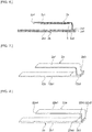
- Figure 7 is a perspective view of first and second elastic plates in a second embodiment.
- This embodiment is different from the first embodiment in that the thickness of a second planar section 12b1 of a second elastic plate 12b is smaller than the thickness of a second joining section 12b3.
- the thickness of the second joining section 12b3 of the second elastic plate 12b is larger than the thickness of the first elastic plate 2a. Therefore, the second elastic plate 12b less easily bends. A decrease in the strength of vibration less easily occurs.
- the thickness of the second planar section 12b1 is smaller than the thickness of the second joining section 12b3, in vibration, the mass adding member much less easily collides with the second elastic plate 12b. Therefore, a decrease in the strength of vibration involved in a reduction in size and thickness much less easily occurs.
- Figure 8 is a perspective view of first and second elastic plates in a third embodiment.
- This embodiment is different from the first embodiment in that, in a first elastic plate 22a, a first joining section 22a3 extends from a first linking section 22a2 in a direction approaching a first end portion 22a4.
- the first joining section 22a3 includes a surface extending in parallel to the second planar section 2b1 of the second elastic plate 2b.
- the first joining section 22a3 is joined to the second elastic plate 2b on the surface.
- the first joining section 22a3 includes a portion overlapping a first planar section 22a1 in plan view. Therefore, it is possible to promote a reduction in the size of the vibration device.
- Figure 9 is a perspective view of first and second elastic plates in a fourth embodiment.
- This embodiment is different from the first embodiment in that a first elastic plate 32a is flat and that a second elastic plate 32b includes a portion bent to the first elastic plate 32a side.
- the second elastic plate 32b includes a second linking section 32b2 that links a second planar section 32b1 and a second joining section 32b3.
- the second joining section 32b3 is located further on a fourth end portion 32b5 side than the second linking section 32b2.
- the second elastic plate 32b is bent to the first elastic plate 32a side in the second linking section 32b2.
- the second joining section 32b3 extends from the second linking section 32b2 in a direction away from a third end portion 32b4.
- the second joining section 32b3 includes a surface extending in parallel to a first planar section 32a1 of the first elastic plate 32a.
- the second joining section 32b3 is joined to the first elastic plate 32a on the surface.
- the second joining section 32b3 may extend from the second linking section 32b2 in a direction approaching the third end portion 32b4.
- Figure 10 is a perspective view of first and second elastic plates in a fifth embodiment.
- This embodiment is different from the fourth embodiment in that a second joining section 42b3 of a second elastic plate 42b extends toward the first elastic plate 32a side.
- the second joining section 42b3 includes a fourth end portion 42b5.
- the fourth end portion 42b5 includes an end face of the second elastic plate 42b.
- the second joining section 42b3 is joined to the first elastic plate 32a on the end face.
- the second elastic plate may be flat, the first joining section of the first elastic plate may extend toward the second elastic plate, and the first elastic plate may be joined to the second elastic plate on the end face on the second end portion side.
- Figure 11(a) is a perspective view of first and second elastic plates in a sixth embodiment.
- Figure 11(b) is a rear view of the first and second elastic plates in the sixth embodiment.
- this embodiment is different from the fourth embodiment in that a second elastic plate 52b includes a projecting section 52b6 projecting to the first elastic plate 32a side on a fourth end portion 52b5 side.
- the second elastic plate 52b is joined to the first elastic plate 32a in the projecting section 52b6.
- the projecting section 52b6 includes a surface extending in parallel to the first planar section 32a1 of the first elastic plate 32a.
- the projecting section 52b6 is joined to the first elastic plate 32a on the surface.
- the projecting section 52b6 is formed by bending the fourth end portion 52b5 side of the second elastic plate 52b. As shown in Figure 11(b) , a portion where the projecting section 52b6 is formed is a concave section opened to a surface on the opposite side of the first elastic plate 32a side of the second elastic plate 52b.
- the thickness of the second elastic plate 52b in the projecting section 52b6 is the same thickness as the thickness of a second planar section 52b1 shown in Figure 11(a) . Note that the thickness of the second elastic plate 52b in the projecting section 52b6 only has to be the same thickness as the thickness of at least a part other than the projecting section 52b6 in the second elastic plate 52b.
- the vibration device is mounted from a lower surface in Figure 11(a) of the second elastic plate 52b. At this point, a portion other than the projecting section 52b6 of the surface in the second elastic plate 52b can be brought into contact with a target on which the vibration device is mounted. Therefore, it is possible to increase an area of the second elastic plate 52b in contact with the target on which the vibration device is mounted. Therefore, it is possible to efficiently propagate vibration to the outside.
- the projecting section 52b6 desirably includes the fourth end portion 52b5. Consequently, it is possible to include the fourth end portion 52b5 in a portion where the second elastic plate 52b joints with the first elastic plate 32a. Therefore, it is possible to promote a reduction in the size of the vibration device.
Landscapes
- Physics & Mathematics (AREA)
- Acoustics & Sound (AREA)
- Engineering & Computer Science (AREA)
- Mechanical Engineering (AREA)
- Chemical & Material Sciences (AREA)
- Ceramic Engineering (AREA)
- Apparatuses For Generation Of Mechanical Vibrations (AREA)
- Piezo-Electric Or Mechanical Vibrators, Or Delay Or Filter Circuits (AREA)
- Telephone Set Structure (AREA)
- General Electrical Machinery Utilizing Piezoelectricity, Electrostriction Or Magnetostriction (AREA)
Abstract
Description
- The present invention relates to a vibration device in which a piezoelectric vibrating element is fixed to an elastic plate such as a metal plate.
- Various vibration devices have been proposed as a vibration device used, for example, for the purpose of notifying an incoming call.
Patent Literature 1 described blow discloses an example of such a vibration device. The vibration device described inPatent Literature 1 includes an elastic plate obtained by bending a metal plate to have a U shape when viewed from a side. One side of the elastic plate is formed as a tabular fixed section and the other side of the elastic plate is formed as a tabular vibrating section with a bent section therebetween. A piezoelectric vibrating plate is provided in the vibrating section. - Patent Literature 1:
WO 2010/023801 - In the vibration device of this type, a further reduction in size and thickness is demanded according to a reduction in the sizes of mounted components resulting from a reduction in the sizes and improvement of the functions of electronic devices and the like. The strength of vibration tends to be low according to the reduction in the size and the thickness of the vibration device.
- An object of the present invention is to provide a vibration device in which a decrease in the strength of vibration involved in a reduction in thickness and size less easily occurs.
- A vibration device according to the present invention includes: a first elastic plate including first and second end portions and a first planar section located between the first and second end portions; a second elastic plate joined to the second end portion side of the first elastic plate, including a second planar section opposed to the first planar section of the first elastic plate, and having flexural rigidity higher than flexural rigidity of the first elastic plate; a piezoelectric vibrating element provided on a surface on a second elastic plate side in the first planar section of the first elastic plate; and a mass adding member attached to the first end portion of the first elastic plate.
- In a certain specific aspect of the vibration device according to the present invention, the vibration device further includes a package member provided to house the first elastic plate to which the piezoelectric vibrating element and the mass adding member are attached. In this case, it is possible to increase the strength of the vibration device.
- In another specific aspect of the vibration device according to the present invention, the vibration device further includes a circuit section provided on a surface on a first elastic plate side in the second planar section of the second elastic plate and forming at least a part of a circuit for driving the piezoelectric vibrating element.
- In still another specific aspect of the vibration device according to the present invention, thickness of the second elastic plate is larger than thickness of the first elastic plate. In this case, it is possible effectively increase the flexural rigidity of the second elastic plate.
- In another specific aspect of the vibration device according to the present invention, a material of the second elastic plate has flexural rigidity higher than flexural rigidity of a material of the first elastic plate. In this case, it is possible to effectively increase the flexural rigidity of the second elastic plate.
- In still another specific aspect of the vibration device according to the present invention, the first elastic plate includes a first joining section joined to the second elastic plate and a first linking section that links the first joining section and the first planar section, the first joining section is located further on the second end portion side than the first linking section, and the first elastic plate is bent to the second elastic plate side in the first linking section.
- In still another specific aspect of the vibration device according to the present invention, the first joining section extends from the first linking section in a direction away from the first end portion, and the first joining section includes a surface extending in parallel to the second planar section of the second elastic plate and is joined to the second elastic plate on the surface. In this case, it is possible to promote a reduction in size.
- In still another specific aspect of the vibration device according to the present invention, the first joining section extends from the first linking section in a direction approaching the first end portion, and the first joining section includes a surface extending in parallel to the second planar section of the second elastic plate and is joined to the second elastic plate on the surface.
- In still another specific aspect of the vibration device according to the present invention, the second elastic plate includes third and fourth end portions, a second joining section in which the second elastic plate is joined to the first elastic plate, and a second linking section that links the second joining section and the second planar section, the second planar section is located between the third and fourth end portions, the second joining section is located further on a fourth end portion side than the second linking section, and the second elastic plate is bent to the first elastic plate side in the second linking section.
- In still another specific aspect of the vibration device according to the present invention, the second joining section extends from the second linking section in a direction away from the third end portion, and the second joining section includes a surface extending in parallel to the first planar section of the first elastic plate and is joined to the first elastic plate on the surface.
- In still another specific aspect of the vibration device according to the present invention, the second joining section includes the fourth end portion, the fourth end portion includes an end face of the second elastic plate, and the second joining section is joined to the first elastic plate on the end face. In this case, it is possible to reduce a joining area of the first elastic plate and the second elastic plate. Therefore, it is possible to promote a reduction in the size of the vibration device.
- In still another aspect of the vibration device according to the present invention, the second elastic plate includes third and fourth end portions and a projecting section projecting to the first elastic plate side on the fourth end portion side, and the projecting section is jointed to the first elastic plate. In this case, it is possible to increase an area of contact of the second elastic plate with a target on which the vibration device is mounted. Therefore, it is possible to efficiently propagate vibration to the outside.
- In still another specific aspect of the vibration device according to the present invention, thickness of the projecting section is the same as thickness of at least a part of other than the projecting section in the second elastic plate, and a portion where the projecting section is formed is a concave section opened to a surface on an opposite side of the first elastic plate side of the second elastic plate.
- In still another specific aspect of the vibration device according to the present invention, the projecting section includes the fourth end portion of the second elastic plate. In this case, it is possible to promote a reduction in the size of the vibration device.
- In still another specific aspect of the vibration device according to the present invention, thickness of the second planar section of the second elastic plate is smaller than thickness of a portion where the second elastic plate is jointed to the first elastic plate. In this case, the mass adding member much less easily collides with the second elastic plate. Therefore, a decrease in the strength of vibration involved in a reduction in thickness and size much less easily occurs.
- In still another specific aspect of the vibration device according to the present invention, the second elastic plate includes third and fourth end portions, and a portion where the first elastic plate and the second elastic plate are joined includes at least one of the second end portion of the first elastic plate and the fourth end portion of the second elastic plate. In this case, it is possible to promote a reduction in the size of the vibration device.
- In still another specific aspect of the vibration device according to the present invention, a direction connecting the first and second end portions of the first elastic plate is a longitudinal direction of the first elastic plate.
- In still another specific aspect of the vibration device according to the present invention, the first and second elastic plates are made of metal. In this case, it is possible to prevent a decrease in the strength of vibration in the first and second elastic plates.
- According to the present invention, it is possible to provide a vibration device in which a decrease in the strength of vibration involved in a reduction in thickness and size less easily occurs.
-
- [
Figure 1] Figure 1 is a perspective view of a vibration device according to a first embodiment of the present invention. - [
Figure 2] Figure 2 is a side sectional view of the vibration device according to the first embodiment of the present invention. - [
Figure 3] Figure 3 is an exploded perspective view of the vibration device according to the first embodiment of the present invention. - [
Figure 4] Figure 4(a) is a side view of a piezoelectric vibrating element in the first embodiment of the present invention andFigure 4(b) is a plan view of the piezoelectric vibrating element in the first embodiment. - [
Figure 5] Figure 5 is a plan view showing, in an exploded state, the piezoelectric vibrating element, a circuit board, and a flexible printed wiring board for explaining a state of connection of the piezoelectric vibrating element and the circuit board in the first embodiment of the present invention. - [
Figure 6] Figure 6 is a schematic diagram for explaining vibration of first and second elastic plates in the first embodiment of the present invention. - [
Figure 7] Figure 7 is a perspective view of first and second elastic plates in a second embodiment of the present invention. - [
Figure 8] Figure 8 is a perspective view of first and second elastic plates in a third embodiment of the present invention. - [
Figure 9] Figure 9 is a perspective view of first and second elastic plates in a fourth embodiment of the present invention. - [
Figure 10] Figure 10 is a perspective view of first and second elastic plates in a fifth embodiment of the present invention. - [
Figure 11] Figure 11(a) is a perspective view of first and second elastic plates in a sixth embodiment of the present invention andFigure 11(b) is a rear view of the first and second elastic plates in the sixth embodiment. - The present invention is clarified by explaining specific embodiments of the present invention below while referring to the drawings.
- Note that it is pointed out that the embodiments described in this specification are illustrative and partial substitution or combination of components is possible among different embodiments.
-
Figure 1 is a perspective view showing the exterior of a vibration device according to a first embodiment of the present invention.Figure 2 is a side sectional view of the vibration device according to the first embodiment.Figure 3 is an exploded perspective view of the vibration device according to the first embodiment. - A
vibration device 1 shown inFigure 1 to Figure 3 can be used for, for example, a vibration notifying function of a portable electronic device. As shown inFigure 2 , thevibration device 1 includes a firstelastic plate 2a. The firstelastic plate 2a includes first and second end portions 2a4 and 2a5. In this embodiment, in plan view, a direction connecting the first end portion 2a4 and the second end portion 2a5 is a longitudinal direction of the firstelastic plate 2a. - The
vibration device 1 includes a secondelastic plate 2b connected to the second end portion 2a5 side of the firstelastic plate 2a. The secondelastic plate 2b includes third and fourth end portions 2b4 and 2b5. The secondelastic plate 2b includes a second joining section 2b3 located on the fourth end portion 2b5 side. The secondelastic plate 2b is connected to the firstelastic plate 2a in the second joining section 2b3. In this embodiment, a direction connecting the third end portion 2b4 and the fourth end portion 2b5 is a longitudinal direction of the secondelastic plate 2b. Note that the longitudinal directions in the first and secondelastic plates - The thickness of the second
elastic plate 2b is larger than the thickness of the firstelastic plate 2a. Further, the material of the secondelastic plate 2b has flexural rigidity higher than the flexural rigidity of the material of the firstelastic plate 2a. Consequently, the secondelastic plate 2b has flexural rigidity higher than the flexural rigidity of the firstelastic plate 2a. Note that the flexural rigidity refers to a characteristic indicating difficulty of flexural deformation of an object at the time when force is applied to the object. High flexural rigidity means that the object is less easily flexurally deformed. - More specifically, the first
elastic plate 2a is made of SUS304 and the secondelastic plate 2b is made of SUS301. Note that the first and secondelastic plates elastic plates elastic plates - Note that the first and second
elastic plates elastic plate 2b higher than the elastic rigidity of the firstelastic plate 2a by differentiating thicknesses or the like. Alternatively, the thicknesses of the first and secondelastic plates elastic plate 2b higher than the flexural rigidity of the firstelastic plate 2a by using different materials or the like. - The first
elastic plate 2a includes a first planar section 2a1, a first linking section 2a2, and a first joining section 2a3 located between the first and second end portions 2a4 and 2a5. The first planar section 2a1 has a plane shape. The distal end portion of the first planar section 2a1 is located at the first end portion 2a4. The first linking section 2a2 connects the first planar section 2a1 and the first joining section 2a3. The first joining section 2a3 is joined to the secondelastic plate 2b. The distal end portion of the first joining section 2a3 is located at the second end portion 2a5. - On the other hand, the second
elastic plate 2b includes a second planar section 2b1 and the second joining section 2b3 located between the third and fourth end portions 2b4 and 2b5. The second planar section 2b1 has a plane shape. The second planar section 2b1 of the secondelastic plate 2b is opposed to the first planar section 2a1 of the firstelastic plate 2a. The second joining section 2b3 is joined to the first joining section 2a3 of the firstelastic plate 2a. - The first
elastic plate 2a is bent to the secondelastic plate 2b side in the first linking section 2a2. The first joining section 2a3 extends from the first linking section 2a2 in a direction away from the first end portion 2a4. The first joining section 2a3 includes a surface extending in parallel to the second planar section 2b1 of the secondelastic plate 2b. The first joining section 2a3 is joined to the secondelastic plate 2b on the surface. The firstelastic plate 2a and the secondelastic plate 2b are desirably joined by welding. Consequently, it is possible to effectively increase joining strength. - The welding can be performed by, for example, irradiation of laser light. Note that the joining of the first and second
elastic plates - As shown in
Figure 2 , the first linking section 2a2 is located between an alternate long and short dash line A and an alternate long and short dash line B. Both end portions of the first linking section 2a2 are bent. Note that at least one of both the end portions of the first linking section 2a2 may be bent to have a corner portion. - A piezoelectric vibrating
element 3 is provided in the first planar section 2a1 of the firstelastic plate 2a. More specifically, the piezoelectric vibratingelement 3 is provided on a surface on the secondelastic plate 2b side in the first planar section 2a1. The piezoelectric vibratingelement 3 is fixed to the firstelastic plate 2a using an appropriate adhesive such as a thermosetting resin adhesive. The piezoelectric vibratingelement 3 has a rectangular tabular shape. -
Figure 4(a) is a side view of the piezoelectric vibrating element in the first embodiment.Figure 4(b) is a plan view of the piezoelectric vibrating element in the first embodiment. - As shown in
Figure 4(a) , the piezoelectric vibratingelement 3 includes apiezoelectric layer 4. Thepiezoelectric layer 4 includes a firstprincipal plane 4a and a secondprincipal plane 4b opposed to the firstprincipal plane 4a. The piezoelectric vibratingelement 3 is fixed to the first elastic plate from the firstprincipal plane 4a side. - As indicated by a broken line in
Figure 4(b) , afirst electrode 5a and asecond electrode 5b are provided on the secondprincipal plane 4b of thepiezoelectric layer 4. As shown inFigure 4(a) , athird electrode 5c is provided on the firstprincipal plane 4a to be opposed to thefirst electrode 5a with thepiezoelectric layer 4 interposed therebetween. Thethird electrode 5c is electrically connected to thesecond electrode 5b by a via hole electrode or by a connection electrode (not shown in the figure) through a side surface of thepiezoelectric layer 4. - As a material configuring the
piezoelectric layer 4, appropriate piezoelectric ceramics such as PZT ceramics can be used. The first tothird electrodes 5a to 5c are made of appropriate metal or alloy. However, in the present invention, the configuration of the piezoelectric vibratingelement 3 is not particularly limited. - An AC electric field is applied between the first and
third electrodes element 3, whereby the piezoelectric vibratingelement 3 expands and contracts in the in-plane direction. When the piezoelectric vibratingelement 3 expands and contracts, a warp occurs in the firstelastic plate 2a shown inFigure 2 . According to the occurrence of the warp, the firstelastic plate 2a repeats a state in which the first end portion 2a4 is displaced downward inFigure 2 and a state in which the first end portion 2a4 is displaced upward and vibrates. The vibration of the firstelastic plate 2a is propagated to the secondelastic plate 2b via the first joining section 2a3. Thevibration device 1 is mounted from the secondelastic plate 2b side. Vibration of thevibration device 1 is propagated from the secondelastic plate 2b to the outside. Consequently, the vibration notifying function and the like are achieved. - A characteristic of this embodiment resides in that the
vibration device 1 includes the firstelastic plate 2a on which the piezoelectric vibratingelement 3 is provided and the secondelastic plate 2b joined to the firstelastic plate 2a and the secondelastic plate 2b has the flexural rigidity higher than the flexural rigidity of the firstelastic plate 2a. Consequently, a decrease in the strength of vibration of the secondelastic plate 2b involved in a reduction in the thickness and the size of thevibration device 1 less easily occurs. Therefore, it is possible to efficiently propagate the vibration from the secondelastic plate 2b to the outside. Details are explained below. - As shown in
Figure 2 andFigure 3 , acircuit board 6 functioning as a circuit section is provided in the second planar section 2b1 of the secondelastic plate 2b. More specifically, thecircuit board 6 is provided on a surface on the firstelastic plate 2a side in the second planar section 2b1. - As the
circuit board 6, a glass epoxy board or an appropriate board material made of synthetic resin such as polyimide can be used. At least a part of a driving circuit for feeding electric power to the piezoelectric vibratingelement 3 and driving the piezoelectric vibratingelement 3 is formed on thecircuit board 6. - The
circuit board 6 is electrically connected to the piezoelectric vibratingelement 3 by a flexible printedwiring board 7. The flexible printedwiring board 7 is configured using a resin film having flexibility such as thermosetting polyimide. A conductive adhesive, solder, and the like can be used for connection of thecircuit board 6 and the piezoelectric vibratingelement 3 to the flexible printedwiring board 7. -
Figure 5 is a plan view showing, in an exploded state, the piezoelectric vibrating element, the circuit board, and the flexible printed wiring board for explaining a state of connection of the piezoelectric vibrating element and the circuit board in the first embodiment. - The flexible printed
wiring board 7 includes first electric connecting sections 7a1 and 7a2, a secondelectric connecting section 7b, third electric connecting sections 7c1 and 7c2, and awire linking section 7d. The first electric connecting sections 7a1 and 7a2 are connected to the outside. The first electric connecting section 7a1 and the first electric connecting section 7a2 are connected to different potentials. The first electric connecting sections 7a1 and 7a2 are electrically connected to the secondelectric connecting section 7b by wires 7e1 and 7e2. - The
circuit board 6 is placed on the secondelectric connecting section 7b. The secondelectric connecting section 7b and thecircuit board 6 are electrically connected. The secondelectric connecting section 7b is electrically connected to the third electric connecting sections 7c1 and 7c2 by wires 7e3 and 7e4 that pass through thewire linking section 7d. - The third electric connecting sections 7c1 and 7c2 are connected to the piezoelectric vibrating
element 3. More specifically, the third electric connecting section 7c1 is connected to thefirst electrode 5a of the piezoelectric vibratingelement 3. The third electric connecting section 7c2 is connected to thesecond electrode 5b of the piezoelectric vibratingelement 3. - As shown in
Figure 2 , the flexible printedwiring board 7 is fixed to a surface on the firstelastic plate 2a side in the second planar section 2b1 of the secondelastic plate 2b. The fixing can be performed using an appropriate adhesive or an appropriate adhesive sheet. Thewire linking section 7d is bent such that the second electric connecting section is disposed on the secondelastic plate 2b and the third electric connecting section is disposed on the firstelastic plate 2a. - In manufacturing of the
vibration device 1, electric connection work can be performed in a state in which the piezoelectric vibratingelement 3, thecircuit board 6, and the flexible printedwiring board 7 are developed as shown inFigure 5 . Therefore, it is possible to easily perform the electric connection work. - Note that the circuit section is not limited to the circuit board. The circuit section only has to form at least a part of a circuit for driving the piezoelectric vibrating
element 3. For example, the circuit section may be formed by a wiring element. The configuration of connection of the circuit section and the piezoelectric vibratingelement 3 is not particularly limited either. The circuit section and the piezoelectric vibratingelement 3 may be connected by a lead wire or the like. - As shown in
Figure 1 , the first electric connecting sections 7a1 and 7a2 of the flexible printedwiring board 7 further protrude sideward than the secondelastic plate 2b and apackage member 9 explained below. Therefore, it is possible to easily perform electric connection to the outside. - As shown in
Figure 2 , amass adding member 8 is attached to the first end portion 2a4 of the firstelastic plate 2a. A resonance frequency of thevibration device 1 can be adjusted by themass adding member 8. By adding themass adding member 8, it is possible to increase a distal end mass of a pendulum formed by the firstelastic plate 2a and increase the vibration of thevibration device 1. Themass adding member 8 is made of appropriate metal, a combined material of metal and resin, ceramics, or the like. It is desirable that themass adding member 8 is made of metal having high density such as tungsten because mass adding action is high. - The
mass adding member 8 includes a firstprincipal plane 8A located on the firstelastic plate 2a side and a secondprincipal plane 8B located on the secondelastic plate 2b side. - The first
principal plane 8A of themass adding member 8 has a step-wise shape. More specifically, the firstprincipal plane 8A includes a thirdplanar section 8a, a fourthplanar section 8b, and a fifthplanar section 8c linked via steps. The height of the step between the thirdplanar section 8a and the fourthplanar section 8b is set equal to the thickness of the firstelastic plate 2a. - The first end portion 2a4 of the first
elastic plate 2a is provided in the fourthplanar section 8b. More specifically, the first end portion 2a4 of the firstelastic plate 2a is disposed near the step. The vicinity of the first end portion 2a4 is placed in the fourthplanar section 8b. - The fourth
planar section 8b and the fifthplanar section 8c are also linked via another step. The distal end portion of the piezoelectric vibratingelement 3 is disposed near the step. In this embodiment, the distal end portion of a portion disposed on the firstelastic plate 2a side in the flexible printedwiring board 7 reaches the distal end portion. The height of the other step is set equal to or larger than a total of the thicknesses of the piezoelectric vibratingelement 3 and the flexible printedwiring board 7. Therefore, the thicknesses of the firstelastic plate 2a, the piezoelectric vibratingelement 3, and the flexible printedwiring board 7 are absorbed within the total dimension of the heights of the steps and the other step. Therefore, it is possible to fix themass adding member 8 to the first end portion 2a4 of the firstelastic plate 2a without causing an increase in size. - Note that the flexible printed
wiring board 7 does not have to reach a position overlapping themass adding member 8 in plan view. In this case, the height of the other step of themass adding member 8 is desirably equal to or larger than the thickness of the piezoelectric vibratingelement 3. - The third
planar section 8a is formed as an inclined surface. At least a part of the secondprincipal plane 8B is also an inclined surface. Consequently, the thickness of the mass adding member 8 (the distance between the firstprincipal plane 8A of themass adding member 8 and the secondprincipal plane 8B of the mass adding member 8) decreases further away from the first end portion 2a4 of the firstelastic plate 2a. Consequently, in vibration of the firstelastic plate 2a, themass adding member 8 less easily collides with the secondelastic plate 2b and atop plate section 9a of apackage member 9 explained below. Therefore, it is possible to more efficiently propagate the vibration to the outside. - Note that the shape of the
mass adding member 8 is not particularly limited. - The
vibration device 1 includes apackage member 9 functioning as a cover member. Thepackage member 9 is provided to house the firstelastic plate 2a to which the piezoelectric vibratingelement 3 and themass adding member 8 are attached. - As shown in
Figure 1 , thepackage member 9 includes atop plate section 9a and first to fourthside surface sections 9b to 9e, one ends of which are linked to thetop plate section 9a. The first and thirdside surface sections side surface sections - The first
side surface section 9b is located on the first end portion 2a4 side of the firstelastic plate 2a. The thirdside surface section 9d is located on the second end portion 2a5 side. Note that thepackage member 9 does not have to include at least one of the first and thirdside surface sections package member 9 includes the first and thirdside surface sections vibration device 1. - The
package member 9 is made of appropriate metal or synthetic resin. Thepackage member 9 is desirably made of metal because the metal is excellent in mechanical strength. Thepackage member 9 is more desirably made of stainless steel because the stainless steel is excellent in rust prevention. - As explained above, in this embodiment, the second
elastic plate 2b has the flexural rigidity higher than the flexural rigidity of the firstelastic plate 2a. Consequently, a decrease in the strength of vibration involved in a reduction in the thickness and the size of thevibration device 1 less easily occurs. This is explained with reference toFigure 6 below. -
Figure 6 is a schematic diagram of a side cross section for explaining vibration of the first and second elastic plates in the first embodiment. - By applying an AC electric field to the piezoelectric vibrating
element 3, as indicated by an alternate long and short dash line inFigure 6 , the firstelastic plate 2a repeats a state in which the first end portion 2a4 is displaced downward inFigure 6 and a state in which the first end portion 2a4 is displaced upward and vibrates. The vibration is propagated from the first joining section 2a3 to the secondelastic plate 2b. Since the secondelastic plate 2b has the flexural rigidity of higher than the flexural rigidity of the firstelastic plate 2a, the secondelastic plate 2b is less easily bent by the vibration. Therefore, as indicated by an alternate long and two short dashes line inFigure 6 , the entire secondelastic plate 2b vibrates up and down. Therefore, the strength of the vibration propagated to the secondelastic plate 2b is less easily attenuated. Therefore, even if a reduction in thickness and size is promoted, a decrease in the strength of vibration less easily occurs. - Further, as shown in
Figure 2 , thepackage member 9 is not provided on a side where thevibration device 1 is mounted in the secondelastic plate 2b. Thevibration device 1 is mounted such that the secondelastic plate 2b is in contact with a target to which the vibration is propagated. Therefore, it is possible to more efficiently propagate the vibration to the outside. - In the second
elastic plate 2b, bending due to the vibration propagated from the firstelastic plate 2a less easily occurs. Therefore, in the mounting of thevibration device 1, for example, a double-sided adhesive tape that is easily deformed and less easily prevents bending of the secondelastic plate 2b can also be used. Even if the double-side adhesive tape or the like is used, deterioration in propagation efficiency of vibration is less easily caused. It is possible easily mount thevibration device 1. - A portion where the first
elastic plate 2a and the secondelastic plate 2b are joined desirably includes at least one of the second end portion 2a5 of the firstelastic plate 2a and the fourth end portion 2b5 of the secondelastic plate 2b. Consequently, it is possible to promote a reduction in the size of thevibration device 1. However, more desirably, as in this embodiment, the portion where the first and secondelastic plates vibration device 1. - In
Figure 7 to Figure 10 andFigure 11(a) and Figure 11(b) referred to below, vibration devices according to second to sixth embodiments having the configurations of the first and second elastic plates different from the configuration in the first embodiment are shown. In the vibration devices according to the second to sixth embodiments, like thevibration device 1 in the first embodiment, a decrease in the strength of vibration involved in a reduction in thickness and size less easily occurs. Note that, inFigure 7 to Figure 10 andFigure 11(a) and Figure 11(b) , only the configurations of the first and second elastic plates of the vibration device are shown. -
Figure 7 is a perspective view of first and second elastic plates in a second embodiment. - This embodiment is different from the first embodiment in that the thickness of a second planar section 12b1 of a second
elastic plate 12b is smaller than the thickness of a second joining section 12b3. - The thickness of the second joining section 12b3 of the second
elastic plate 12b is larger than the thickness of the firstelastic plate 2a. Therefore, the secondelastic plate 12b less easily bends. A decrease in the strength of vibration less easily occurs. - Since the thickness of the second planar section 12b1 is smaller than the thickness of the second joining section 12b3, in vibration, the mass adding member much less easily collides with the second
elastic plate 12b. Therefore, a decrease in the strength of vibration involved in a reduction in size and thickness much less easily occurs. -
Figure 8 is a perspective view of first and second elastic plates in a third embodiment. - This embodiment is different from the first embodiment in that, in a first
elastic plate 22a, a first joining section 22a3 extends from a first linking section 22a2 in a direction approaching a first end portion 22a4. - More specifically, the first joining section 22a3 includes a surface extending in parallel to the second planar section 2b1 of the second
elastic plate 2b. The first joining section 22a3 is joined to the secondelastic plate 2b on the surface. - The first joining section 22a3 includes a portion overlapping a first planar section 22a1 in plan view. Therefore, it is possible to promote a reduction in the size of the vibration device.
-
Figure 9 is a perspective view of first and second elastic plates in a fourth embodiment. - This embodiment is different from the first embodiment in that a first
elastic plate 32a is flat and that a secondelastic plate 32b includes a portion bent to the firstelastic plate 32a side. - More specifically, the second
elastic plate 32b includes a second linking section 32b2 that links a second planar section 32b1 and a second joining section 32b3. The second joining section 32b3 is located further on a fourth end portion 32b5 side than the second linking section 32b2. - The second
elastic plate 32b is bent to the firstelastic plate 32a side in the second linking section 32b2. The second joining section 32b3 extends from the second linking section 32b2 in a direction away from a third end portion 32b4. The second joining section 32b3 includes a surface extending in parallel to a first planar section 32a1 of the firstelastic plate 32a. The second joining section 32b3 is joined to the firstelastic plate 32a on the surface. - Note that the second joining section 32b3 may extend from the second linking section 32b2 in a direction approaching the third end portion 32b4.
-
Figure 10 is a perspective view of first and second elastic plates in a fifth embodiment. - This embodiment is different from the fourth embodiment in that a second joining section 42b3 of a second
elastic plate 42b extends toward the firstelastic plate 32a side. The second joining section 42b3 includes a fourth end portion 42b5. The fourth end portion 42b5 includes an end face of the secondelastic plate 42b. The second joining section 42b3 is joined to the firstelastic plate 32a on the end face. - In this embodiment, it is possible to reduce a contact area of the first
elastic plate 32a and the secondelastic plate 42b. Therefore, it is possible to promote a reduction in the size of the vibration device. - Note that the second elastic plate may be flat, the first joining section of the first elastic plate may extend toward the second elastic plate, and the first elastic plate may be joined to the second elastic plate on the end face on the second end portion side.
-
Figure 11(a) is a perspective view of first and second elastic plates in a sixth embodiment.Figure 11(b) is a rear view of the first and second elastic plates in the sixth embodiment. - As shown in
Figure 11(a) , this embodiment is different from the fourth embodiment in that a secondelastic plate 52b includes a projecting section 52b6 projecting to the firstelastic plate 32a side on a fourth end portion 52b5 side. The secondelastic plate 52b is joined to the firstelastic plate 32a in the projecting section 52b6. - More specifically, the projecting section 52b6 includes a surface extending in parallel to the first planar section 32a1 of the first
elastic plate 32a. The projecting section 52b6 is joined to the firstelastic plate 32a on the surface. - The projecting section 52b6 is formed by bending the fourth end portion 52b5 side of the second
elastic plate 52b. As shown inFigure 11(b) , a portion where the projecting section 52b6 is formed is a concave section opened to a surface on the opposite side of the firstelastic plate 32a side of the secondelastic plate 52b. The thickness of the secondelastic plate 52b in the projecting section 52b6 is the same thickness as the thickness of a second planar section 52b1 shown inFigure 11(a) . Note that the thickness of the secondelastic plate 52b in the projecting section 52b6 only has to be the same thickness as the thickness of at least a part other than the projecting section 52b6 in the secondelastic plate 52b. - The vibration device is mounted from a lower surface in
Figure 11(a) of the secondelastic plate 52b. At this point, a portion other than the projecting section 52b6 of the surface in the secondelastic plate 52b can be brought into contact with a target on which the vibration device is mounted. Therefore, it is possible to increase an area of the secondelastic plate 52b in contact with the target on which the vibration device is mounted. Therefore, it is possible to efficiently propagate vibration to the outside. - The projecting section 52b6 desirably includes the fourth end portion 52b5. Consequently, it is possible to include the fourth end portion 52b5 in a portion where the second
elastic plate 52b joints with the firstelastic plate 32a. Therefore, it is possible to promote a reduction in the size of the vibration device. -
- 1
- vibration device
- 2a
- first elastic plate
- 2a1
- first planar section
- 2a2
- first linking section
- 2a3
- first joining section
- 2a4, 2a5
- first and second end portions
- 2b
- second elastic plate
- 2b1
- second planar section
- 2b3
- second joining section
- 2b4, 2b5
- third and fourth end portions
- 3
- piezoelectric vibrating element
- 4
- piezoelectric layer
- 4a, 4b
- first and second principal planes
- 5a to 5c
- first to third electrodes
- 6
- circuit board
- 7
- flexible printed wiring board
- 7al, 7a2
- first electric connecting sections
- 7b
- second electric connecting section
- 7c1, 7c2
- third electric connecting sections
- 7d
- wire linking section
- 7e1 to 7e4
- wires
- 8
- mass adding member
- 8A, 8B
- first and second principal planes
- 8a to 8c
- third to fifth planar sections
- 9
- package member
- 9a
- top plate section
- 9b to 9e
- first to fourth side surface sections
- 12b
- second elastic plate
- 12b1
- second planar section
- 12b3
- second joining section
- 22a
- first elastic plate
- 22a1
- first planar section
- 22a2
- first linking section
- 22a3
- first joining section
- 22a4, 22a5
- first and second end portions
- 32a
- first elastic plate
- 32a1
- first planar section
- 32b
- second elastic plate
- 32b1
- second planar section
- 32b2
- second linking section
- 32b3
- second joining section
- 32b4, 32b5
- third and fourth end portions
- 42b
- second elastic plate
- 42b3
- second joining section
- 42b5
- fourth end portion
- 52b
- second elastic plate
- 52b1
- second planar section
- 52b5
- fourth end portion
- 52b6
- projecting section
Claims (18)
- A vibration device comprising:a first elastic plate including first and second end portions and a first planar section located between the first and second end portions;a second elastic plate joined to the second end portion side of the first elastic plate, including a second planar section opposed to the first planar section of the first elastic plate, and having flexural rigidity higher than flexural rigidity of the first elastic plate;a piezoelectric vibrating element provided on a surface on a second elastic plate side in the first planar section of the first elastic plate; anda mass adding member attached to the first end portion of the first elastic plate.
- The vibration device according to claim 1, further comprising a package member provided to house the first elastic plate to which the piezoelectric vibrating element and the mass adding member are attached.
- The vibration device according to claim 1 or 2, further comprising a circuit section provided on a surface on a first elastic plate side in the second planar section of the second elastic plate and forming at least a part of a circuit for driving the piezoelectric vibrating element.
- The vibration device according to any one of claims 1 to 3, wherein thickness of the second elastic plate is larger than thickness of the first elastic plate.
- The vibration device according to any one of claims 1 to 4, wherein a material of the second elastic plate has flexural rigidity higher than flexural rigidity of a material of the first elastic plate.
- The vibration device according to any one of claims 1 to 5, wherein
the first elastic plate includes a first joining section joined to the second elastic plate and a first linking section that links the first joining section and the first planar section,
the first joining section is located further on the second end portion side than the first linking section, and
the first elastic plate is bent to the second elastic plate side in the first linking section. - The vibration device according to claim 6, wherein the first joining section extends from the first linking section in a direction away from the first end portion, and the first joining section includes a surface extending in parallel to the second planar section of the second elastic plate and is joined to the second elastic plate on the surface.
- The vibration device according to claim 6, wherein the first joining section extends from the first linking section in a direction approaching the first end portion, and the first joining section includes a surface extending in parallel to the second planar section of the second elastic plate and is joined to the second elastic plate on the surface.
- The vibration device according to any one of claims 1 to 5, wherein
the second elastic plate includes third and fourth end portions, a second joining section in which the second elastic plate is joined to the first elastic plate, and a second linking section that links the second joining section and the second planar section,
the second planar section is located between the third and fourth end portions, the second joining section is located further on a fourth end portion side than the second linking section, and
the second elastic plate is bent to the first elastic plate side in the second linking section. - The vibration device according to claim 9, wherein the second joining section extends from the second linking section in a direction away from the third end portion, and the second joining section includes a surface extending in parallel to the first planar section of the first elastic plate and is joined to the first elastic plate on the surface.
- The vibration device according to claim 9, wherein the second joining section includes the fourth end portion, the fourth end portion includes an end face of the second elastic plate, and the second joining section is joined to the first elastic plate on the end face.
- The vibration device according to any one of claims 1 to 5, wherein the second elastic plate includes third and fourth end portions and a projecting section projecting to the first elastic plate side on the fourth end portion side, and the projecting section is jointed to the first elastic plate.
- The vibration device according to claim 12, wherein thickness of the projecting section is the same as thickness of at least a part of other than the projecting section in the second elastic plate, and a portion where the projecting section is formed is a concave section opened to a surface on an opposite side of the first elastic plate side of the second elastic plate.
- The vibration device according to claim 12 or 13, wherein the projecting section includes the fourth end portion of the second elastic plate.
- The vibration device according to any one of claims 1 to 14, wherein thickness of the second planar section of the second elastic plate is smaller than thickness of a portion where the second elastic plate is jointed to the first elastic plate.
- The vibration device according to any one of claims 1 to 15, wherein the second elastic plate includes third and fourth end portions, and a portion where the first elastic plate and the second elastic plate are joined includes at least one of the second end portion of the first elastic plate and the fourth end portion of the second elastic plate.
- The vibration device according to any one of claims 1 to 16, wherein a direction connecting the first and second end portions of the first elastic plate is a longitudinal direction of the first elastic plate.
- The vibration device according to any one of claims 1 to 17, wherein the first and second elastic plates are made of metal.
Applications Claiming Priority (2)
| Application Number | Priority Date | Filing Date | Title |
|---|---|---|---|
| JP2016016128 | 2016-01-29 | ||
| PCT/JP2017/001012 WO2017130738A1 (en) | 2016-01-29 | 2017-01-13 | Vibration device |
Publications (3)
| Publication Number | Publication Date |
|---|---|
| EP3320987A1 true EP3320987A1 (en) | 2018-05-16 |
| EP3320987A4 EP3320987A4 (en) | 2019-03-20 |
| EP3320987B1 EP3320987B1 (en) | 2021-01-13 |
Family
ID=59398857
Family Applications (1)
| Application Number | Title | Priority Date | Filing Date |
|---|---|---|---|
| EP17743969.2A Active EP3320987B1 (en) | 2016-01-29 | 2017-01-13 | Vibration device |
Country Status (5)
| Country | Link |
|---|---|
| US (1) | US10848123B2 (en) |
| EP (1) | EP3320987B1 (en) |
| JP (1) | JP6311854B2 (en) |
| CN (1) | CN108472687A (en) |
| WO (1) | WO2017130738A1 (en) |
Families Citing this family (7)
| Publication number | Priority date | Publication date | Assignee | Title |
|---|---|---|---|---|
| JP6269822B2 (en) * | 2014-04-24 | 2018-01-31 | 株式会社村田製作所 | Vibration device |
| KR102692565B1 (en) | 2018-11-20 | 2024-08-07 | 삼성전자주식회사 | resonator and resonator system including the same and method of manufacturing the resonator |
| JP7136318B2 (en) * | 2019-02-22 | 2022-09-13 | 株式会社村田製作所 | Vibration device and its manufacturing method |
| CN113348039B (en) * | 2019-02-22 | 2022-05-13 | 株式会社村田制作所 | Vibration device |
| CN112838784B (en) * | 2021-01-07 | 2023-04-25 | 歌尔微电子股份有限公司 | Piezoelectric vibration motor |
| US12046475B2 (en) | 2021-01-14 | 2024-07-23 | Taiwan Semiconductor Manufacturing Co., Ltd. | Surface oxidation control of metal gates using capping layer |
| CN115763166A (en) * | 2022-12-05 | 2023-03-07 | 贵州电网有限责任公司 | A low pressure air switch |
Family Cites Families (12)
| Publication number | Priority date | Publication date | Assignee | Title |
|---|---|---|---|---|
| US5796152A (en) * | 1997-01-24 | 1998-08-18 | Roxburgh Ltd. | Cantilevered microstructure |
| JPH10272418A (en) | 1997-03-31 | 1998-10-13 | Ceratec:Kk | Incoming vibration device and portable receiver with incoming vibration device |
| JPH11313395A (en) * | 1998-04-27 | 1999-11-09 | Kyocera Corp | Electric vibration converter |
| JP4188304B2 (en) * | 2004-11-26 | 2008-11-26 | ホシデン株式会社 | Piezoelectric actuator, flat panel speaker |
| WO2009141970A1 (en) * | 2008-05-19 | 2009-11-26 | 株式会社村田製作所 | Vibrating device |
| WO2010023801A1 (en) | 2008-08-27 | 2010-03-04 | 株式会社村田製作所 | Vibrating device |
| JP2011043925A (en) * | 2009-08-19 | 2011-03-03 | Nissha Printing Co Ltd | Flexurally vibrating actuator and touch panel with tactile sensation feedback function using the same |
| JP6268999B2 (en) * | 2013-12-06 | 2018-01-31 | セイコーエプソン株式会社 | Piezoelectric motor, robot hand, robot, finger assist device, electronic component transport device, electronic component inspection device, liquid feed pump, printing device, electronic clock, projection device |
| JP6269822B2 (en) * | 2014-04-24 | 2018-01-31 | 株式会社村田製作所 | Vibration device |
| KR101640446B1 (en) * | 2014-10-10 | 2016-07-18 | 주식회사 엠플러스 | Piezoelectric vibration actuator |
| JP2018019065A (en) * | 2016-07-27 | 2018-02-01 | モダ−イノチップス シーオー エルティディー | Piezoelectric vibration device and electronic apparatus including the same |
| JP6693564B2 (en) * | 2016-09-12 | 2020-05-13 | 株式会社村田製作所 | Vibration device and manufacturing method thereof |
-
2017
- 2017-01-13 JP JP2017564157A patent/JP6311854B2/en active Active
- 2017-01-13 CN CN201780005473.2A patent/CN108472687A/en active Pending
- 2017-01-13 EP EP17743969.2A patent/EP3320987B1/en active Active
- 2017-01-13 WO PCT/JP2017/001012 patent/WO2017130738A1/en not_active Ceased
-
2018
- 2018-01-09 US US15/865,814 patent/US10848123B2/en active Active
Also Published As
| Publication number | Publication date |
|---|---|
| JP6311854B2 (en) | 2018-04-18 |
| US10848123B2 (en) | 2020-11-24 |
| JPWO2017130738A1 (en) | 2018-04-19 |
| CN108472687A (en) | 2018-08-31 |
| EP3320987B1 (en) | 2021-01-13 |
| WO2017130738A1 (en) | 2017-08-03 |
| US20180131346A1 (en) | 2018-05-10 |
| EP3320987A4 (en) | 2019-03-20 |
Similar Documents
| Publication | Publication Date | Title |
|---|---|---|
| EP3320987A1 (en) | Vibration device | |
| US10639676B2 (en) | Vibration device | |
| JP5304791B2 (en) | Vibration device | |
| US9743166B2 (en) | Device generating sound | |
| CN110461089B (en) | electronic device | |
| JPWO2012073656A1 (en) | Piezoelectric generator and manufacturing method thereof | |
| US12017252B2 (en) | Vibration device | |
| US20190240697A1 (en) | Vibration device and method of manufacturing the same | |
| CN103390597A (en) | Semiconductor device | |
| JPWO2020170937A1 (en) | Vibration device and its manufacturing method | |
| JP6648862B2 (en) | Vibration device and driving method thereof | |
| CN107251659A (en) | The manufacture method of flexible base board, the part with flexible base board and the part with flexible base board | |
| JP4724147B2 (en) | Multilayer ceramic capacitor and its mounting structure | |
| CN110402012A (en) | Electronic equipment | |
| KR20070040727A (en) | Angular velocity sensor | |
| JP4877999B2 (en) | Condenser microphone | |
| JP6588235B2 (en) | Connection parts, connection structure and communication device | |
| CN111753737A (en) | A fingerprint module and electronic equipment | |
| JP2018027006A5 (en) | ||
| JP2014013001A (en) | Piezoelectric fan | |
| KR20160056204A (en) | Vibrator | |
| KR20160056203A (en) | Vibrator |
Legal Events
| Date | Code | Title | Description |
|---|---|---|---|
| STAA | Information on the status of an ep patent application or granted ep patent |
Free format text: STATUS: THE INTERNATIONAL PUBLICATION HAS BEEN MADE |
|
| PUAI | Public reference made under article 153(3) epc to a published international application that has entered the european phase |
Free format text: ORIGINAL CODE: 0009012 |
|
| STAA | Information on the status of an ep patent application or granted ep patent |
Free format text: STATUS: REQUEST FOR EXAMINATION WAS MADE |
|
| 17P | Request for examination filed |
Effective date: 20180206 |
|
| AK | Designated contracting states |
Kind code of ref document: A1 Designated state(s): AL AT BE BG CH CY CZ DE DK EE ES FI FR GB GR HR HU IE IS IT LI LT LU LV MC MK MT NL NO PL PT RO RS SE SI SK SM TR |
|
| AX | Request for extension of the european patent |
Extension state: BA ME |
|
| A4 | Supplementary search report drawn up and despatched |
Effective date: 20190218 |
|
| RIC1 | Information provided on ipc code assigned before grant |
Ipc: H03H 9/13 20060101ALI20190212BHEP Ipc: H03H 9/17 20060101ALI20190212BHEP Ipc: H01L 41/187 20060101ALI20190212BHEP Ipc: B06B 1/06 20060101AFI20190212BHEP Ipc: H03H 9/10 20060101ALI20190212BHEP Ipc: H03H 9/09 20060101ALI20190212BHEP |
|
| DAV | Request for validation of the european patent (deleted) | ||
| DAX | Request for extension of the european patent (deleted) | ||
| STAA | Information on the status of an ep patent application or granted ep patent |
Free format text: STATUS: EXAMINATION IS IN PROGRESS |
|
| 17Q | First examination report despatched |
Effective date: 20190927 |
|
| GRAP | Despatch of communication of intention to grant a patent |
Free format text: ORIGINAL CODE: EPIDOSNIGR1 |
|
| STAA | Information on the status of an ep patent application or granted ep patent |
Free format text: STATUS: GRANT OF PATENT IS INTENDED |
|
| RIC1 | Information provided on ipc code assigned before grant |
Ipc: H03H 9/13 20060101ALI20200710BHEP Ipc: H03H 9/17 20060101ALI20200710BHEP Ipc: H01L 41/09 20060101ALI20200710BHEP Ipc: H01L 41/187 20060101ALI20200710BHEP Ipc: B06B 1/06 20060101AFI20200710BHEP Ipc: H03H 9/10 20060101ALI20200710BHEP Ipc: H03H 9/09 20060101ALI20200710BHEP |
|
| INTG | Intention to grant announced |
Effective date: 20200729 |
|
| RIN1 | Information on inventor provided before grant (corrected) |
Inventor name: KAGAYAMA, KENJI Inventor name: OBARA, HIROAKI Inventor name: NISHII, TAKAHIRO |
|
| GRAS | Grant fee paid |
Free format text: ORIGINAL CODE: EPIDOSNIGR3 |
|
| GRAA | (expected) grant |
Free format text: ORIGINAL CODE: 0009210 |
|
| STAA | Information on the status of an ep patent application or granted ep patent |
Free format text: STATUS: THE PATENT HAS BEEN GRANTED |
|
| AK | Designated contracting states |
Kind code of ref document: B1 Designated state(s): AL AT BE BG CH CY CZ DE DK EE ES FI FR GB GR HR HU IE IS IT LI LT LU LV MC MK MT NL NO PL PT RO RS SE SI SK SM TR |
|
| REG | Reference to a national code |
Ref country code: GB Ref legal event code: FG4D |
|
| REG | Reference to a national code |
Ref country code: CH Ref legal event code: EP |
|
| REG | Reference to a national code |
Ref country code: IE Ref legal event code: FG4D |
|
| REG | Reference to a national code |
Ref country code: DE Ref legal event code: R096 Ref document number: 602017031379 Country of ref document: DE |
|
| REG | Reference to a national code |
Ref country code: AT Ref legal event code: REF Ref document number: 1354161 Country of ref document: AT Kind code of ref document: T Effective date: 20210215 |
|
| REG | Reference to a national code |
Ref country code: AT Ref legal event code: MK05 Ref document number: 1354161 Country of ref document: AT Kind code of ref document: T Effective date: 20210113 |
|
| REG | Reference to a national code |
Ref country code: NL Ref legal event code: MP Effective date: 20210113 |
|
| REG | Reference to a national code |
Ref country code: LT Ref legal event code: MG9D |
|
| PG25 | Lapsed in a contracting state [announced via postgrant information from national office to epo] |
Ref country code: BG Free format text: LAPSE BECAUSE OF FAILURE TO SUBMIT A TRANSLATION OF THE DESCRIPTION OR TO PAY THE FEE WITHIN THE PRESCRIBED TIME-LIMIT Effective date: 20210413 Ref country code: LT Free format text: LAPSE BECAUSE OF FAILURE TO SUBMIT A TRANSLATION OF THE DESCRIPTION OR TO PAY THE FEE WITHIN THE PRESCRIBED TIME-LIMIT Effective date: 20210113 Ref country code: HR Free format text: LAPSE BECAUSE OF FAILURE TO SUBMIT A TRANSLATION OF THE DESCRIPTION OR TO PAY THE FEE WITHIN THE PRESCRIBED TIME-LIMIT Effective date: 20210113 Ref country code: GR Free format text: LAPSE BECAUSE OF FAILURE TO SUBMIT A TRANSLATION OF THE DESCRIPTION OR TO PAY THE FEE WITHIN THE PRESCRIBED TIME-LIMIT Effective date: 20210414 Ref country code: FI Free format text: LAPSE BECAUSE OF FAILURE TO SUBMIT A TRANSLATION OF THE DESCRIPTION OR TO PAY THE FEE WITHIN THE PRESCRIBED TIME-LIMIT Effective date: 20210113 Ref country code: PT Free format text: LAPSE BECAUSE OF FAILURE TO SUBMIT A TRANSLATION OF THE DESCRIPTION OR TO PAY THE FEE WITHIN THE PRESCRIBED TIME-LIMIT Effective date: 20210513 Ref country code: NO Free format text: LAPSE BECAUSE OF FAILURE TO SUBMIT A TRANSLATION OF THE DESCRIPTION OR TO PAY THE FEE WITHIN THE PRESCRIBED TIME-LIMIT Effective date: 20210413 |
|
| PG25 | Lapsed in a contracting state [announced via postgrant information from national office to epo] |
Ref country code: SE Free format text: LAPSE BECAUSE OF FAILURE TO SUBMIT A TRANSLATION OF THE DESCRIPTION OR TO PAY THE FEE WITHIN THE PRESCRIBED TIME-LIMIT Effective date: 20210113 Ref country code: RS Free format text: LAPSE BECAUSE OF FAILURE TO SUBMIT A TRANSLATION OF THE DESCRIPTION OR TO PAY THE FEE WITHIN THE PRESCRIBED TIME-LIMIT Effective date: 20210113 Ref country code: LV Free format text: LAPSE BECAUSE OF FAILURE TO SUBMIT A TRANSLATION OF THE DESCRIPTION OR TO PAY THE FEE WITHIN THE PRESCRIBED TIME-LIMIT Effective date: 20210113 Ref country code: PL Free format text: LAPSE BECAUSE OF FAILURE TO SUBMIT A TRANSLATION OF THE DESCRIPTION OR TO PAY THE FEE WITHIN THE PRESCRIBED TIME-LIMIT Effective date: 20210113 Ref country code: AT Free format text: LAPSE BECAUSE OF FAILURE TO SUBMIT A TRANSLATION OF THE DESCRIPTION OR TO PAY THE FEE WITHIN THE PRESCRIBED TIME-LIMIT Effective date: 20210113 |
|
| REG | Reference to a national code |
Ref country code: CH Ref legal event code: PL |
|
| PG25 | Lapsed in a contracting state [announced via postgrant information from national office to epo] |
Ref country code: LU Free format text: LAPSE BECAUSE OF NON-PAYMENT OF DUE FEES Effective date: 20210113 Ref country code: IS Free format text: LAPSE BECAUSE OF FAILURE TO SUBMIT A TRANSLATION OF THE DESCRIPTION OR TO PAY THE FEE WITHIN THE PRESCRIBED TIME-LIMIT Effective date: 20210513 |
|
| REG | Reference to a national code |
Ref country code: BE Ref legal event code: MM Effective date: 20210131 |
|
| REG | Reference to a national code |
Ref country code: DE Ref legal event code: R097 Ref document number: 602017031379 Country of ref document: DE |
|
| PG25 | Lapsed in a contracting state [announced via postgrant information from national office to epo] |
Ref country code: EE Free format text: LAPSE BECAUSE OF FAILURE TO SUBMIT A TRANSLATION OF THE DESCRIPTION OR TO PAY THE FEE WITHIN THE PRESCRIBED TIME-LIMIT Effective date: 20210113 Ref country code: CZ Free format text: LAPSE BECAUSE OF FAILURE TO SUBMIT A TRANSLATION OF THE DESCRIPTION OR TO PAY THE FEE WITHIN THE PRESCRIBED TIME-LIMIT Effective date: 20210113 Ref country code: MC Free format text: LAPSE BECAUSE OF FAILURE TO SUBMIT A TRANSLATION OF THE DESCRIPTION OR TO PAY THE FEE WITHIN THE PRESCRIBED TIME-LIMIT Effective date: 20210113 Ref country code: SM Free format text: LAPSE BECAUSE OF FAILURE TO SUBMIT A TRANSLATION OF THE DESCRIPTION OR TO PAY THE FEE WITHIN THE PRESCRIBED TIME-LIMIT Effective date: 20210113 |
|
| PLBE | No opposition filed within time limit |
Free format text: ORIGINAL CODE: 0009261 |
|
| STAA | Information on the status of an ep patent application or granted ep patent |
Free format text: STATUS: NO OPPOSITION FILED WITHIN TIME LIMIT |
|
| PG25 | Lapsed in a contracting state [announced via postgrant information from national office to epo] |
Ref country code: RO Free format text: LAPSE BECAUSE OF FAILURE TO SUBMIT A TRANSLATION OF THE DESCRIPTION OR TO PAY THE FEE WITHIN THE PRESCRIBED TIME-LIMIT Effective date: 20210113 Ref country code: SK Free format text: LAPSE BECAUSE OF FAILURE TO SUBMIT A TRANSLATION OF THE DESCRIPTION OR TO PAY THE FEE WITHIN THE PRESCRIBED TIME-LIMIT Effective date: 20210113 Ref country code: CH Free format text: LAPSE BECAUSE OF NON-PAYMENT OF DUE FEES Effective date: 20210131 Ref country code: DK Free format text: LAPSE BECAUSE OF FAILURE TO SUBMIT A TRANSLATION OF THE DESCRIPTION OR TO PAY THE FEE WITHIN THE PRESCRIBED TIME-LIMIT Effective date: 20210113 Ref country code: LI Free format text: LAPSE BECAUSE OF NON-PAYMENT OF DUE FEES Effective date: 20210131 |
|
| 26N | No opposition filed |
Effective date: 20211014 |
|
| GBPC | Gb: european patent ceased through non-payment of renewal fee |
Effective date: 20210413 |
|
| PG25 | Lapsed in a contracting state [announced via postgrant information from national office to epo] |
Ref country code: FR Free format text: LAPSE BECAUSE OF NON-PAYMENT OF DUE FEES Effective date: 20210313 Ref country code: IE Free format text: LAPSE BECAUSE OF NON-PAYMENT OF DUE FEES Effective date: 20210113 Ref country code: AL Free format text: LAPSE BECAUSE OF FAILURE TO SUBMIT A TRANSLATION OF THE DESCRIPTION OR TO PAY THE FEE WITHIN THE PRESCRIBED TIME-LIMIT Effective date: 20210113 Ref country code: ES Free format text: LAPSE BECAUSE OF FAILURE TO SUBMIT A TRANSLATION OF THE DESCRIPTION OR TO PAY THE FEE WITHIN THE PRESCRIBED TIME-LIMIT Effective date: 20210113 Ref country code: GB Free format text: LAPSE BECAUSE OF NON-PAYMENT OF DUE FEES Effective date: 20210413 |
|
| PG25 | Lapsed in a contracting state [announced via postgrant information from national office to epo] |
Ref country code: SI Free format text: LAPSE BECAUSE OF FAILURE TO SUBMIT A TRANSLATION OF THE DESCRIPTION OR TO PAY THE FEE WITHIN THE PRESCRIBED TIME-LIMIT Effective date: 20210113 |
|
| PG25 | Lapsed in a contracting state [announced via postgrant information from national office to epo] |
Ref country code: IT Free format text: LAPSE BECAUSE OF FAILURE TO SUBMIT A TRANSLATION OF THE DESCRIPTION OR TO PAY THE FEE WITHIN THE PRESCRIBED TIME-LIMIT Effective date: 20210113 |
|
| PG25 | Lapsed in a contracting state [announced via postgrant information from national office to epo] |
Ref country code: IS Free format text: LAPSE BECAUSE OF FAILURE TO SUBMIT A TRANSLATION OF THE DESCRIPTION OR TO PAY THE FEE WITHIN THE PRESCRIBED TIME-LIMIT Effective date: 20210513 |
|
| PG25 | Lapsed in a contracting state [announced via postgrant information from national office to epo] |
Ref country code: BE Free format text: LAPSE BECAUSE OF NON-PAYMENT OF DUE FEES Effective date: 20210131 |
|
| PG25 | Lapsed in a contracting state [announced via postgrant information from national office to epo] |
Ref country code: NL Free format text: LAPSE BECAUSE OF NON-PAYMENT OF DUE FEES Effective date: 20210113 Ref country code: CY Free format text: LAPSE BECAUSE OF FAILURE TO SUBMIT A TRANSLATION OF THE DESCRIPTION OR TO PAY THE FEE WITHIN THE PRESCRIBED TIME-LIMIT Effective date: 20210113 |
|
| PG25 | Lapsed in a contracting state [announced via postgrant information from national office to epo] |
Ref country code: HU Free format text: LAPSE BECAUSE OF FAILURE TO SUBMIT A TRANSLATION OF THE DESCRIPTION OR TO PAY THE FEE WITHIN THE PRESCRIBED TIME-LIMIT; INVALID AB INITIO Effective date: 20170113 |
|
| PG25 | Lapsed in a contracting state [announced via postgrant information from national office to epo] |
Ref country code: MK Free format text: LAPSE BECAUSE OF FAILURE TO SUBMIT A TRANSLATION OF THE DESCRIPTION OR TO PAY THE FEE WITHIN THE PRESCRIBED TIME-LIMIT Effective date: 20210113 |
|
| PG25 | Lapsed in a contracting state [announced via postgrant information from national office to epo] |
Ref country code: TR Free format text: LAPSE BECAUSE OF FAILURE TO SUBMIT A TRANSLATION OF THE DESCRIPTION OR TO PAY THE FEE WITHIN THE PRESCRIBED TIME-LIMIT Effective date: 20210113 |
|
| PG25 | Lapsed in a contracting state [announced via postgrant information from national office to epo] |
Ref country code: MT Free format text: LAPSE BECAUSE OF FAILURE TO SUBMIT A TRANSLATION OF THE DESCRIPTION OR TO PAY THE FEE WITHIN THE PRESCRIBED TIME-LIMIT Effective date: 20210113 |
|
| PGFP | Annual fee paid to national office [announced via postgrant information from national office to epo] |
Ref country code: DE Payment date: 20260121 Year of fee payment: 10 |