EP3320954A1 - On-board aircraft reactive inerting dried gas system - Google Patents
On-board aircraft reactive inerting dried gas system Download PDFInfo
- Publication number
- EP3320954A1 EP3320954A1 EP17200886.4A EP17200886A EP3320954A1 EP 3320954 A1 EP3320954 A1 EP 3320954A1 EP 17200886 A EP17200886 A EP 17200886A EP 3320954 A1 EP3320954 A1 EP 3320954A1
- Authority
- EP
- European Patent Office
- Prior art keywords
- oxygen
- gas
- water
- membrane
- depleted
- Prior art date
- Legal status (The legal status is an assumption and is not a legal conclusion. Google has not performed a legal analysis and makes no representation as to the accuracy of the status listed.)
- Granted
Links
- QVGXLLKOCUKJST-UHFFFAOYSA-N atomic oxygen Chemical compound [O] QVGXLLKOCUKJST-UHFFFAOYSA-N 0.000 claims abstract description 113
- 239000001301 oxygen Substances 0.000 claims abstract description 113
- 229910052760 oxygen Inorganic materials 0.000 claims abstract description 113
- 239000007789 gas Substances 0.000 claims abstract description 108
- XLYOFNOQVPJJNP-UHFFFAOYSA-N water Substances O XLYOFNOQVPJJNP-UHFFFAOYSA-N 0.000 claims abstract description 101
- 239000012528 membrane Substances 0.000 claims abstract description 58
- 239000011261 inert gas Substances 0.000 claims abstract description 36
- 239000002828 fuel tank Substances 0.000 claims abstract description 33
- 239000012530 fluid Substances 0.000 claims abstract description 29
- 239000004215 Carbon black (E152) Substances 0.000 claims abstract description 20
- 229930195733 hydrocarbon Natural products 0.000 claims abstract description 20
- 150000002430 hydrocarbons Chemical class 0.000 claims abstract description 20
- IJGRMHOSHXDMSA-UHFFFAOYSA-N Atomic nitrogen Chemical compound N#N IJGRMHOSHXDMSA-UHFFFAOYSA-N 0.000 claims description 24
- 238000004891 communication Methods 0.000 claims description 22
- 238000010521 absorption reaction Methods 0.000 claims description 16
- 239000007788 liquid Substances 0.000 claims description 15
- 229910052757 nitrogen Inorganic materials 0.000 claims description 12
- 239000003054 catalyst Substances 0.000 claims description 7
- 238000006243 chemical reaction Methods 0.000 claims description 6
- 229920000642 polymer Polymers 0.000 claims description 6
- 239000011159 matrix material Substances 0.000 claims description 4
- 238000000034 method Methods 0.000 claims description 4
- 238000004519 manufacturing process Methods 0.000 claims 1
- 239000003570 air Substances 0.000 description 57
- 239000000446 fuel Substances 0.000 description 19
- 238000002485 combustion reaction Methods 0.000 description 9
- 238000001816 cooling Methods 0.000 description 6
- 239000000463 material Substances 0.000 description 6
- -1 poly(ethylene oxide) Polymers 0.000 description 4
- 230000032258 transport Effects 0.000 description 4
- 239000004642 Polyimide Substances 0.000 description 3
- 239000013529 heat transfer fluid Substances 0.000 description 3
- 238000010438 heat treatment Methods 0.000 description 3
- 229920002492 poly(sulfone) Polymers 0.000 description 3
- 229920001721 polyimide Polymers 0.000 description 3
- 238000000926 separation method Methods 0.000 description 3
- 229920003171 Poly (ethylene oxide) Polymers 0.000 description 2
- 230000003197 catalytic effect Effects 0.000 description 2
- 230000018044 dehydration Effects 0.000 description 2
- 238000006297 dehydration reaction Methods 0.000 description 2
- SNRUBQQJIBEYMU-UHFFFAOYSA-N dodecane Chemical compound CCCCCCCCCCCC SNRUBQQJIBEYMU-UHFFFAOYSA-N 0.000 description 2
- 238000005516 engineering process Methods 0.000 description 2
- 230000007613 environmental effect Effects 0.000 description 2
- 239000002360 explosive Substances 0.000 description 2
- 238000007710 freezing Methods 0.000 description 2
- 230000008014 freezing Effects 0.000 description 2
- 239000012466 permeate Substances 0.000 description 2
- 229920000515 polycarbonate Polymers 0.000 description 2
- 239000004417 polycarbonate Substances 0.000 description 2
- 230000008569 process Effects 0.000 description 2
- YSYRISKCBOPJRG-UHFFFAOYSA-N 4,5-difluoro-2,2-bis(trifluoromethyl)-1,3-dioxole Chemical compound FC1=C(F)OC(C(F)(F)F)(C(F)(F)F)O1 YSYRISKCBOPJRG-UHFFFAOYSA-N 0.000 description 1
- 241000894006 Bacteria Species 0.000 description 1
- 230000004075 alteration Effects 0.000 description 1
- 239000012080 ambient air Substances 0.000 description 1
- 238000013459 approach Methods 0.000 description 1
- 230000015572 biosynthetic process Effects 0.000 description 1
- 230000015556 catabolic process Effects 0.000 description 1
- 238000007084 catalytic combustion reaction Methods 0.000 description 1
- 230000006835 compression Effects 0.000 description 1
- 238000007906 compression Methods 0.000 description 1
- 238000009833 condensation Methods 0.000 description 1
- 230000005494 condensation Effects 0.000 description 1
- 230000001143 conditioned effect Effects 0.000 description 1
- 230000003750 conditioning effect Effects 0.000 description 1
- 229920001577 copolymer Polymers 0.000 description 1
- 239000013078 crystal Substances 0.000 description 1
- 230000007423 decrease Effects 0.000 description 1
- 238000006731 degradation reaction Methods 0.000 description 1
- 238000013461 design Methods 0.000 description 1
- 238000001514 detection method Methods 0.000 description 1
- 239000004205 dimethyl polysiloxane Substances 0.000 description 1
- 235000013870 dimethyl polysiloxane Nutrition 0.000 description 1
- KPUWHANPEXNPJT-UHFFFAOYSA-N disiloxane Chemical class [SiH3]O[SiH3] KPUWHANPEXNPJT-UHFFFAOYSA-N 0.000 description 1
- 238000001035 drying Methods 0.000 description 1
- 230000009977 dual effect Effects 0.000 description 1
- 238000001704 evaporation Methods 0.000 description 1
- 230000008020 evaporation Effects 0.000 description 1
- 238000004880 explosion Methods 0.000 description 1
- 238000009413 insulation Methods 0.000 description 1
- 238000012423 maintenance Methods 0.000 description 1
- 239000000203 mixture Substances 0.000 description 1
- 230000037361 pathway Effects 0.000 description 1
- 229920000435 poly(dimethylsiloxane) Polymers 0.000 description 1
- 229920000570 polyether Polymers 0.000 description 1
- 229920005597 polymer membrane Polymers 0.000 description 1
- 230000009467 reduction Effects 0.000 description 1
- 239000003507 refrigerant Substances 0.000 description 1
- 230000004044 response Effects 0.000 description 1
- 229920006395 saturated elastomer Polymers 0.000 description 1
- 229920002379 silicone rubber Polymers 0.000 description 1
- 239000000779 smoke Substances 0.000 description 1
- 238000006467 substitution reaction Methods 0.000 description 1
- 230000001629 suppression Effects 0.000 description 1
- BFKJFAAPBSQJPD-UHFFFAOYSA-N tetrafluoroethene Chemical group FC(F)=C(F)F BFKJFAAPBSQJPD-UHFFFAOYSA-N 0.000 description 1
- 125000000383 tetramethylene group Chemical group [H]C([H])([*:1])C([H])([H])C([H])([H])C([H])([H])[*:2] 0.000 description 1
- 239000010409 thin film Substances 0.000 description 1
- DCGLONGLPGISNX-UHFFFAOYSA-N trimethyl(prop-1-ynyl)silane Chemical compound CC#C[Si](C)(C)C DCGLONGLPGISNX-UHFFFAOYSA-N 0.000 description 1
Images


Classifications
-
- B—PERFORMING OPERATIONS; TRANSPORTING
- B64—AIRCRAFT; AVIATION; COSMONAUTICS
- B64D—EQUIPMENT FOR FITTING IN OR TO AIRCRAFT; FLIGHT SUITS; PARACHUTES; ARRANGEMENTS OR MOUNTING OF POWER PLANTS OR PROPULSION TRANSMISSIONS IN AIRCRAFT
- B64D37/00—Arrangements in connection with fuel supply for power plant
- B64D37/32—Safety measures not otherwise provided for, e.g. preventing explosive conditions
-
- A—HUMAN NECESSITIES
- A62—LIFE-SAVING; FIRE-FIGHTING
- A62C—FIRE-FIGHTING
- A62C3/00—Fire prevention, containment or extinguishing specially adapted for particular objects or places
- A62C3/07—Fire prevention, containment or extinguishing specially adapted for particular objects or places in vehicles, e.g. in road vehicles
- A62C3/08—Fire prevention, containment or extinguishing specially adapted for particular objects or places in vehicles, e.g. in road vehicles in aircraft
-
- B—PERFORMING OPERATIONS; TRANSPORTING
- B01—PHYSICAL OR CHEMICAL PROCESSES OR APPARATUS IN GENERAL
- B01D—SEPARATION
- B01D5/00—Condensation of vapours; Recovering volatile solvents by condensation
- B01D5/0003—Condensation of vapours; Recovering volatile solvents by condensation by using heat-exchange surfaces for indirect contact between gases or vapours and the cooling medium
-
- B—PERFORMING OPERATIONS; TRANSPORTING
- B01—PHYSICAL OR CHEMICAL PROCESSES OR APPARATUS IN GENERAL
- B01D—SEPARATION
- B01D5/00—Condensation of vapours; Recovering volatile solvents by condensation
- B01D5/0057—Condensation of vapours; Recovering volatile solvents by condensation in combination with other processes
- B01D5/0075—Condensation of vapours; Recovering volatile solvents by condensation in combination with other processes with heat exchanging
-
- B—PERFORMING OPERATIONS; TRANSPORTING
- B01—PHYSICAL OR CHEMICAL PROCESSES OR APPARATUS IN GENERAL
- B01D—SEPARATION
- B01D53/00—Separation of gases or vapours; Recovering vapours of volatile solvents from gases; Chemical or biological purification of waste gases, e.g. engine exhaust gases, smoke, fumes, flue gases, aerosols
- B01D53/26—Drying gases or vapours
- B01D53/265—Drying gases or vapours by refrigeration (condensation)
-
- B—PERFORMING OPERATIONS; TRANSPORTING
- B01—PHYSICAL OR CHEMICAL PROCESSES OR APPARATUS IN GENERAL
- B01D—SEPARATION
- B01D53/00—Separation of gases or vapours; Recovering vapours of volatile solvents from gases; Chemical or biological purification of waste gases, e.g. engine exhaust gases, smoke, fumes, flue gases, aerosols
- B01D53/26—Drying gases or vapours
- B01D53/266—Drying gases or vapours by filtration
-
- B—PERFORMING OPERATIONS; TRANSPORTING
- B01—PHYSICAL OR CHEMICAL PROCESSES OR APPARATUS IN GENERAL
- B01D—SEPARATION
- B01D53/00—Separation of gases or vapours; Recovering vapours of volatile solvents from gases; Chemical or biological purification of waste gases, e.g. engine exhaust gases, smoke, fumes, flue gases, aerosols
- B01D53/26—Drying gases or vapours
- B01D53/268—Drying gases or vapours by diffusion
-
- B—PERFORMING OPERATIONS; TRANSPORTING
- B01—PHYSICAL OR CHEMICAL PROCESSES OR APPARATUS IN GENERAL
- B01D—SEPARATION
- B01D2258/00—Sources of waste gases
- B01D2258/01—Engine exhaust gases
-
- B—PERFORMING OPERATIONS; TRANSPORTING
- B01—PHYSICAL OR CHEMICAL PROCESSES OR APPARATUS IN GENERAL
- B01D—SEPARATION
- B01D2259/00—Type of treatment
- B01D2259/45—Gas separation or purification devices adapted for specific applications
- B01D2259/4566—Gas separation or purification devices adapted for specific applications for use in transportation means
- B01D2259/4575—Gas separation or purification devices adapted for specific applications for use in transportation means in aeroplanes or space ships
-
- Y—GENERAL TAGGING OF NEW TECHNOLOGICAL DEVELOPMENTS; GENERAL TAGGING OF CROSS-SECTIONAL TECHNOLOGIES SPANNING OVER SEVERAL SECTIONS OF THE IPC; TECHNICAL SUBJECTS COVERED BY FORMER USPC CROSS-REFERENCE ART COLLECTIONS [XRACs] AND DIGESTS
- Y02—TECHNOLOGIES OR APPLICATIONS FOR MITIGATION OR ADAPTATION AGAINST CLIMATE CHANGE
- Y02T—CLIMATE CHANGE MITIGATION TECHNOLOGIES RELATED TO TRANSPORTATION
- Y02T50/00—Aeronautics or air transport
- Y02T50/40—Weight reduction
Definitions
- This disclosure relates to aircraft and aircraft systems, and in particular to an on-board aircraft dried inert gas generation system.
- inerting system decreases the probability of combustion of flammable materials stored in a fuel tank by maintaining a chemically non-reactive or inert gas, such as oxygen-depleted air, in the fuel tank vapor space also known as ullage.
- inert means non-combustible.
- the tank may be made inert by: 1) reducing the oxygen concentration, 2) reducing the fuel concentration of the ullage to below the lower explosive limit (LEL), or 3) increasing the fuel concentration to above the upper explosive limit (UEL).
- LEL lower explosive limit
- UEL upper explosive limit
- Many systems reduce the risk of combustion by reducing the oxygen concentration by introducing an inert gas such as oxygen-depleted air (ODA) to the ullage, thereby displacing oxygen with a mixture of nitrogen and oxygen at target thresholds for avoiding explosion or combustion.
- ODA oxygen-depleted air
- Onboard inert gas systems which supply oxygen-depleted air to the vapor space (i.e., ullage) within the fuel tank.
- the oxygen-depleted air has a substantially reduced oxygen content that reduces or eliminates combustible conditions within the fuel tank.
- Onboard inert gas systems typically use membrane-based gas separators. Such separators contain a membrane that is permeable to oxygen molecules, but relatively impermeable to nitrogen molecules. A pressure differential across the membrane causes oxygen molecules from air on one side of the membrane to pass through the membrane, which forms oxygen-enriched air (OEA) on the low-pressure side of the membrane and ODA on the high-pressure side of the membrane.
- OOA oxygen-enriched air
- bleed-air systems in aircraft; for example Boeing's 787 has a no-bleed systems architecture, which utilizes electrical systems to replace most of the pneumatic systems in order to improve fuel efficiency, as well as reduce weight and lifecycle costs.
- Other aircraft architectures may adopt low-pressure bleed configurations where engine design parameters allow for a bleed flow of compressed air, but at pressures less than the 45 psi air (unless stated otherwise, "psi" as used herein means absolute pressure in pounds per square inch, i.e., psia) that has been typically provided in the past to conventional onboard environmental control systems.
- a separate compressor or compressors can be used to provide pressurized air to the membrane gas separator, but this undesirably increases aircraft payload, and also represents another onboard device with moving parts that is subject to maintenance issues or device failure.
- an on-board aircraft inert gas system comprises a source of hydrocarbon, a source of a gas comprising oxygen, and a first fluid flow path between a gas space in the fuel tank and an inert gas output.
- a reactor is disposed along the first fluid flow path. The reactor comprises an inlet that receives hydrocarbon and the gas comprising oxygen and reacts the hydrocarbon with the oxygen to produce an oxygen-depleted gas comprising water vapor, and an outlet that outputs the oxygen-depleted gas comprising water vapor.
- a first heat exchanger comprises a water-condensing heat rejection side that is disposed along the first fluid flow path.
- the heat rejection side comprises an inlet that receives the oxygen-depleted gas from the reactor and an outlet that outputs oxygen-depleted gas with a reduced water content.
- a heat absorption side of the first heat exchanger is in thermal communication with a heat sink.
- a liquid separator which can be integrated with or separate from the first heat exchanger, separates water condensate produced by the heat rejection side of the first heat exchanger from the oxygen-depleted gas with reduced water content.
- a gas separator comprising a membrane permeable to water comprises a first side of the membrane disposed along the first fluid flow path.
- the separator includes an inlet disposed on the first side of the membrane that receives the oxygen-depleted gas with reduced water content from the first heat exchanger and an outlet that outputs dried oxygen-depleted gas. Water is transported through the membrane to a second side of the membrane, where the separator comprises an outlet that outputs a fluid comprising water.
- a method of generating an inert gas comprises reacting hydrocarbon and oxygen in a gas comprising oxygen to produce an oxygen-depleted gas comprising water vapor. Heat is removed from the oxygen-depleted gas comprising water vapor to condense water vapor in a first heat exchanger, and removing condensate to produce an oxygen-depleted gas having reduced water content. The oxygen-depleted gas having reduced water content is contacted with a membrane permeable to water to produce dried oxygen-depleted gas.
- the reactor can comprise a catalyst that promotes reaction of oxygen with hydrocarbon to produce the oxygen-depleted gas comprising water vapor.
- the heat absorption side of the first heat exchanger can comprise an inlet in communication with a source of aircraft ram air.
- the system can further comprise a second heat exchanger comprising a heat rejection side disposed on the first fluid flow path between the reactor and the first heat exchanger, and a heat absorption side in communication with water from the liquid separator.
- the heat absorption side of the second heat exchanger can comprise an inlet that receives liquid water from the liquid separator and an outlet that outputs water vapor.
- the second side of the gas separator can comprise an inlet that receives a gas having a lower partial water vapor pressure than the oxygen-depleted gas with reduced water content.
- the system can comprise a source of aircraft ram air in fluid communication with the gas separator second side inlet.
- the heat absorption side of the first heat exchanger can comprise an inlet in communication with the source of aircraft ram air and an outlet in communication with the gas separator second side inlet.
- the system can further comprise a source of aircraft engine compressed bleed air in fluid communication with the gas separator second side inlet.
- system can further comprise a vacuum pump in communication with the gas separator second side outlet.
- the membrane can comprise molecule size-selective tortuous paths that selectively allow faster transport of water molecules compared to nitrogen or oxygen molecules.
- the membrane can comprise a polymer matrix that provides greater solubility to water molecules than nitrogen or oxygen molecules.
- the source of gas comprising oxygen can comprise a fuel tank gas space
- the source of hydrocarbon comprises the fuel tank gas space
- a fuel tank vapor comprising the hydrocarbon can be reacted with oxygen in the fuel tank vapor in the presence of a catalyst that promotes reaction of oxygen with hydrocarbon to produce the oxygen-depleted gas comprising water vapor.
- water vapor from the oxygen-depleted gas comprising water vapor can be condensed in a heat exchanger cooled by a source of aircraft ram air.
- the oxygen-depleted gas having reduced water content can have a water content of at least 2 g per kg of the oxygen-depleted gas.
- the oxygen-depleted gas having reduced water content can be contacted with a first side of the membrane permeable to water, and a second side of the membrane can be contacted with a gas having a lower partial water vapor pressure than the oxygen-depleted gas with reduced water content.
- aircraft includes any powered conveyance device capable of sustaining flight.
- FIG. 1 is a schematic depiction of an onboard inert aircraft gas system.
- a left wing vent box 46 is disposed along with wing fuel tank 48 in a wing 50 of an aircraft 52.
- the aircraft 52 depicted in a partial view in FIG.
- 1 also includes a center tank 54 disposed in fuselage 56, and also a right wing and tank and vent box (not shown), with the fuel tanks sharing a common vent system 58 that includes left wing climb vent 60, a left wing dive vent 62, center tank climb vent 64, center tank dive vent 66, and other unnumbered vents depicted by the same circular shapes as the numbered vents.
- a common vent system 58 that includes left wing climb vent 60, a left wing dive vent 62, center tank climb vent 64, center tank dive vent 66, and other unnumbered vents depicted by the same circular shapes as the numbered vents.
- a reactor 132 receives a fluid flow 134 (assisted by ullage blower 135) from ullage gas collection vents 137 and ullage gas collection conduits 139.
- the ullage gas contains air components (oxygen and nitrogen) and fuel vapor and serves as both the source of gas comprising oxygen and the source of hydrocarbon.
- other sources of gas comprising oxygen can be utilized (e.g., outside air), and other sources of hydrocarbon can be used (e.g., liquid fuel).
- the gas comprising oxygen should also comprise at least one other component (e.g., nitrogen from air) to form part of the oxygen-depleted gas after the reaction.
- the reactor can be any type of reactor capable of reacting oxygen with hydrocarbon fuel such as in a combustion reaction. Combustion can be carried out with or without a catalyst. Examples of catalytic reactors and associated equipment are disclosed, for example, in published patent application US 2011/0262309A1 , the disclosure of which is incorporated herein by reference in its entirety.
- the reaction produces an oxygen-depleted stream 138 comprising water and CO 2 as well as residual hydrocarbon, and residual air components (e.g., nitrogen and a reduced amount of oxygen).
- Combustion can be contained to the reactor 132 with the assistance of flame arrestors 141.
- the oxygen-depleted stream 138 is fed first to a heat rejection side of heat exchanger condenser 142 where it is cooled to condense water vapor in the oxygen-depleted stream 138, producing an oxygen-depleted stream with reduced water content 139.
- Heat exchanger condenser 142 also has a heat absorption side in thermal communication with a heat sink.
- the heat sink (i.e., cold source) can be any type of heat sink, including but not limited to ambient air (e.g., fan-assisted blown air), ram air, conditioned air from an on-board ECS air cycle machine, a heat transfer fluid in communication with a heat absorption side of a heat exchanger in an on-board ECS air cycle machine, a heat transfer fluid in communication with a heat absorption side of a heat exchanger in an on-board ECS vapor cycle machine, a heat transfer fluid in communication with an evaporator of a vapor compression refrigerant loop, or liquid fuel in an on-board fuel tank.
- ambient air e.g., fan-assisted blown air
- ram air conditioned air from an on-board ECS air cycle machine
- a heat transfer fluid in communication with a heat absorption side of a heat exchanger in an on-board ECS air cycle machine a heat transfer fluid in communication with a heat absorption side of a heat exchanger in an on-board ECS
- the heat exchanger condenser 142 is depicted as including an integrated liquid water separator or collector (not shown) for collection of condensate 131.
- a liquid water separator can be disposed downstream of the heat exchanger condenser 142 to separate and remove liquid water from the oxygen-depleted stream 139.
- Condensate 131 can be dumped overboard or used in another process (e.g., to provide evaporative cooling in an aircraft ECS).
- the cooling capacity of the heat exchanger condenser 142 may be insufficient to remove enough water from the oxygen-depleted gas to supply to a fuel tank ullage.
- the combustion reaction with jet fuel produces a relatively large amount of water, yielding roughly 13 molecules of water for every molecule of jet fuel (based on Jet-A surrogate dodecane).
- a condenser can reduce water vapor content only to the dew point of the oxygen-depleted gas at the condenser's operating temperature. At lower altitudes such as below 10,000 feet or on the ground, the temperature of available ram air can be above the temperatures needed to remove all of the water in the oxygen-depleted gas.
- the water vapor level of the oxygen-depleted stream 139 exiting from the heat exchanger condenser 142 contains at least 23 g/m 3 of water vapor.
- the water vapor level of the oxygen-depleted stream 139 exiting from the heat exchanger condenser 142 contains at least 19 g per kg of the oxygen-depleted stream 139 (i.e., the oxygen-depleted stream 139 comprises at least 1.9 wt.% water vapor). In some embodiments, the water vapor level of the oxygen-depleted stream 139 exiting from the heat exchanger condenser 142 contains at least 2 g water vapor per kilogram of the oxygen-depleted stream 139 (i.e., the oxygen-depleted stream 139 comprises at least 0.2 wt.% water vapor). In some embodiments, the condenser is cooled with outside air of at least 25°C during one or more operational states.
- the heat exchanger 142 can be sized to maintain a low payload footprint or low demand on ram air such that it does not remove all water even at altitude when ram air is at its coldest.
- Introduction of water into the fuel tanks can cause a number of issues, including condensation inside the tanks which can lead to problems with bacteria growth, ice crystal formation, and fuel quality degradation. Water issues particularly affect while descending from cruise when humid air rushes in and can condense in cold fuel tanks.
- the oxygen-depleted stream 139 exiting from the heat rejection side of heat exchanger condenser 142 has a reduced water content, but as discussed above all water has not necessarily been removed.
- the oxygen-depleted stream 139 is fed to a first side of a gas separator 118 comprising a water-permeable membrane 119.
- the first fluid flow path continues along a first side of the membrane 119 to an inert gas vent line 40 that is in communication with one or more components that utilizes inert gas such as the fuel tank ullage for fuel tank 48 or other fuel tanks, or other inert gas-utilizing components such as a fire suppression system.
- the membrane 119 in different modes of operation, selectively transports water vapor.
- gas separation membranes can rely on one or more physical phenomena for selectivity in transportation of gases across the membrane.
- a selective membrane can rely on size-selective pathways through the membrane that selectively allows transport of smaller molecules over larger molecules. Examples of such membranes include membranes that selectively allow faster transport of smaller water molecules compared to larger nitrogen and oxygen molecules in air.
- Such membranes typically rely on molecule size-selective tortuous paths through a non-porous polymer matrix in the form of a thin film deposited onto a microporous layer.
- the condensability of a molecule is another parameter that can be used in membrane-based gas separations: the more condensable molecule is selectively permeated over the less condensable molecule(s) due to its higher solubility in the polymer matrix, which in turn leads to a larger driving force for permeation.
- selective permeation of water can be accomplished with essentially any polymer-based membrane.
- selective materials for water include polyimides known for use in dehydration applications or 2,2-bistrifluoromethyl-4,5-difluoro-1,3-dioxole/tetrafluoroethylene, silicone rubbers (polydimethyl siloxane, polyoctylmethyl siloxane), polysulfones, polyethers (e.g., a copolymer of poly(ethylene oxide) (PEO) and poly(butylene therephthalate) (PBT), polycarbonates, poly(4-methyl-2-pentyne), poly-trimethyl-silyl-propyne (PTMSP), etc..
- PEO poly(ethylene oxide)
- PBT poly(butylene therephthalate)
- PTMSP poly-trimethyl-silyl-propyne
- the gas selective membrane can include any of the above materials, alone or in combination with each other or other selective materials. Combinations of different materials can be integrated into a single membrane structure (e.g., in layers, or zones in the x-y plane of a membrane structure), or can be disposed in series or in parallel as separate membrane structures or modules.
- any of the aforementioned polymers can selectively permeate water vapor over oxygen and nitrogen, maximizing the membrane's selectivity towards water will minimize the loss of feed air through the membrane during operation when vacuum is the driving force; hence, proper identification of a membrane layer is an important consideration in the case of the membrane dryer connected to a vacuum pump.
- Examples of polymer membranes in this case that can be used with a vacuum pump (or without a vacuum pump) include polyimides, polycarbonates and polysulfones.
- water 148 can be selectively transported across the membrane 119 to a second fluid flow path disposed on a second side of the membrane 119 with a discharge 121 of a fluid comprising water.
- fluid e.g., permeate gas
- flow along the second fluid flow path is provided by heated ram air 146 exhausted from the heat absorption side of the heat exchanger condenser 142.
- the heating of the ram air by the heat exchanger condenser 142 can reduce the relative humidity of the ram air to promote absorption of moisture by the ram air as a sweep gas for the gas separator 118.
- Dried inert air exiting from the gas separator 118 is directed through inert gas vent lines 40 to fuel tank inert gas vents 42.
- the inert gas flow can be aided by a blower (not shown).
- the embodiment depicted in FIG. 1 can accomplish the dual purpose of cooling and drying the combusted inert gas stream, resulting in a much dryer stream entering the fuel tank. Even if outside air is saturated with water vapor, heating it by cooling the inert gas stream raises the temperature such that the air can absorb more water vapor as a sweep gas in the gas separator 118.
- the additional weight of the membrane can in some embodiments be offset by a smaller size of the ram air heat exchanger because of reduced need for temperature reduction of the catalyst exhaust stream since moisture not condensed in the condenser 142 can be removed by the gas separator 118.
- the heated ram air 146 is maintained at or below 180°F (80°C) to accommodate fuel tank specifications.
- 180°F 80°C
- Such an upper limit for the temperature of the inert gas entering an aircraft fuel tank is well within the limits of certain dehydration membranes such as polyimides or polysulfones. The membrane acts as a heat exchanger, so the outside air should not heat up the inert gas beyond this threshold.
- the heated ram air 146 is maintained at or below a temperature of 80°C because inert gas temperatures higher than this may cause evaporation of some lighter fuel fractions leading to an increased load on the reactor 132 and the rest of the inert gas system.
- FIG. 1 is illustrative of a particular example embodiment, and other example embodiments are also contemplated.
- the condensate 131 is shown as exiting the system, e.g., discharged overboard.
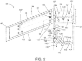
- FIG. 2 is a schematic depiction where the condensate 131 is utilized in the inert gas system. As shown in FIG. 2 , condensate 131 is utilized on a heat absorption side of a second heat exchanger 150 having a heat rejection side disposed on the first flow path between the reactor 132 and the first heat exchanger 142.
- the heat of reaction from the reactor 132 is sufficient to boil or otherwise vaporize condensate 131, thereby absorbing heat from oxygen-depleted gas 138. In some embodiments, this can reduce the heat load on or increase the effectiveness of the first heat exchanger condenser. Since the collection of ram air places an aerodynamic drag on the aircraft resulting in increased fuel consumption, reduced heat load on the heat exchanger condenser 142 can allow for reduced ram air consumption and its accompanying fuel penalty. No condensate collection from the second heat exchanger 150 is shown in FIG. 2 based on an example embodiment where the second heat exchanger 150 does not reduce the temperature of the oxygen-depleted gas below its dew point. In other embodiments, any condensate from the oxygen-depleted gas 138 could be separated and collected with a liquid separator integrated into the second heat exchanger 150 or a separate liquid separator downstream from the second heat exchanger.
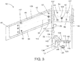
- FIGS. 3 and 4 show additional alternative configurations.
- the water vapor permeating the membrane 119 is collected by a vacuum pump.
- insulation or heating tape can be used along the conduits for the fluid discharge 121 to prevent the permeated water vapor from condensing and freezing before reaching the vent when the system operates at altitudes where the outside temperature is below freezing.
- FIG. 4 depicts an example embodiment where compressed bleed air 154 from an aircraft engine is used as sweep gas for second side of the gas separator 118.
- ram air 144 is dedicated for cooling of the catalyst exhaust stream, and heated ram air 146 can be used in another on-board process or discharged overboard.
- a controller 35 can be in operative communication with the above-referenced components and any associated valves, pumps, compressors, conduits, or other fluid flow components, and with switches, inverters, regulators, sensors, and other electrical system components, and any other system components to selectively operate the inert gas system. These control connections can be through wired electrical signal connections (not shown) or through wireless connections. In some embodiments, the controller 35 can be configured to operate the system according to specified parameters, as discussed in greater detail further below.
- the system can be controlled to set fluid flow rates to produce varying amounts of ODA in response to system parameters.
- system parameters can include, but are not limited to the humidity of the ODA, temperature of the fuel in the vehicle fuel tank(s), oxygen content of the fuel in the fuel tanks, oxygen content of vapor in the ullage of fuel tanks, temperature rise in an enclosed space such as a cargo hold or avionics bay, smoke and/or flame detection in said enclosed spaces, and temperature and/or pressure of vapor in the ullage of fuel tanks, and other on-board parameters such as temperature, oxygen content, and/or humidity level of ullage air.
- the inert gas management system and components thereof such as shown in FIGS.
- 1-4 can include sensors for measuring any of the above-mentioned fluid flow rates, temperatures, oxygen levels, humidity levels, as well as controllable output fans or blowers, or controllable fluid flow control valves or gates. These sensors and controllable devices can be operatively connected to the controller 35, which can be an independent controller dedicated to controlling the inert gas management system, or can interact with other onboard system controllers or with a master controller. In some embodiments, data provided by the controller of the inert gas management system can come directly from a master controller.
Abstract
Description
- This disclosure relates to aircraft and aircraft systems, and in particular to an on-board aircraft dried inert gas generation system.
- It is recognized that fuel vapors within fuel tanks become combustible in the presence of oxygen. An inerting system decreases the probability of combustion of flammable materials stored in a fuel tank by maintaining a chemically non-reactive or inert gas, such as oxygen-depleted air, in the fuel tank vapor space also known as ullage. As used herein, the term "inert" means non-combustible. Three elements are required to initiate and sustain combustion: an ignition source (e.g., heat), fuel, and oxygen. Combustion may be prevented by reducing any one of these three elements. If the presence of an ignition source cannot be prevented within a fuel tank, then the tank may be made inert by: 1) reducing the oxygen concentration, 2) reducing the fuel concentration of the ullage to below the lower explosive limit (LEL), or 3) increasing the fuel concentration to above the upper explosive limit (UEL). Many systems reduce the risk of combustion by reducing the oxygen concentration by introducing an inert gas such as oxygen-depleted air (ODA) to the ullage, thereby displacing oxygen with a mixture of nitrogen and oxygen at target thresholds for avoiding explosion or combustion.
- It is known in the art to equip aircraft with onboard inert gas systems, which supply oxygen-depleted air to the vapor space (i.e., ullage) within the fuel tank. The oxygen-depleted air has a substantially reduced oxygen content that reduces or eliminates combustible conditions within the fuel tank. Onboard inert gas systems typically use membrane-based gas separators. Such separators contain a membrane that is permeable to oxygen molecules, but relatively impermeable to nitrogen molecules. A pressure differential across the membrane causes oxygen molecules from air on one side of the membrane to pass through the membrane, which forms oxygen-enriched air (OEA) on the low-pressure side of the membrane and ODA on the high-pressure side of the membrane. The requirement for a pressure differential necessitates a source of compressed or pressurized air. Bleed air from an aircraft engine or from an onboard auxiliary power unit can provide a source of compressed air; however, this can reduce available engine power and also must compete with other onboard demands for compressed air, such as the onboard air environmental conditioning system and anti-ice systems. Moreover, certain flight conditions such as during aircraft descent can lead to an increased demand for ODA at precisely the time when engines could be throttled back for fuel savings so that that maintaining sufficient compressed air pressure for meeting the pneumatic demands may come at a significant fuel burn cost. Additionally, there is a trend to reduce or eliminate bleed-air systems in aircraft; for example Boeing's 787 has a no-bleed systems architecture, which utilizes electrical systems to replace most of the pneumatic systems in order to improve fuel efficiency, as well as reduce weight and lifecycle costs. Other aircraft architectures may adopt low-pressure bleed configurations where engine design parameters allow for a bleed flow of compressed air, but at pressures less than the 45 psi air (unless stated otherwise, "psi" as used herein means absolute pressure in pounds per square inch, i.e., psia) that has been typically provided in the past to conventional onboard environmental control systems. A separate compressor or compressors can be used to provide pressurized air to the membrane gas separator, but this undesirably increases aircraft payload, and also represents another onboard device with moving parts that is subject to maintenance issues or device failure.
- Alternate technologies have been proposed for aircraft fuel tank inerting, including the use of electrochemical cells or catalytic reactors to produce inerting gas. However, neither of these technologies has yet achieved commercial success, and new approaches for aircraft fuel tank inerting continue to be pursued.
- According to some embodiments of this disclosure, an on-board aircraft inert gas system comprises a source of hydrocarbon, a source of a gas comprising oxygen, and a first fluid flow path between a gas space in the fuel tank and an inert gas output. A reactor is disposed along the first fluid flow path. The reactor comprises an inlet that receives hydrocarbon and the gas comprising oxygen and reacts the hydrocarbon with the oxygen to produce an oxygen-depleted gas comprising water vapor, and an outlet that outputs the oxygen-depleted gas comprising water vapor. A first heat exchanger comprises a water-condensing heat rejection side that is disposed along the first fluid flow path. The heat rejection side comprises an inlet that receives the oxygen-depleted gas from the reactor and an outlet that outputs oxygen-depleted gas with a reduced water content. A heat absorption side of the first heat exchanger is in thermal communication with a heat sink. A liquid separator, which can be integrated with or separate from the first heat exchanger, separates water condensate produced by the heat rejection side of the first heat exchanger from the oxygen-depleted gas with reduced water content. A gas separator comprising a membrane permeable to water comprises a first side of the membrane disposed along the first fluid flow path. The separator includes an inlet disposed on the first side of the membrane that receives the oxygen-depleted gas with reduced water content from the first heat exchanger and an outlet that outputs dried oxygen-depleted gas. Water is transported through the membrane to a second side of the membrane, where the separator comprises an outlet that outputs a fluid comprising water.
- In some embodiments of the disclosure, a method of generating an inert gas comprises reacting hydrocarbon and oxygen in a gas comprising oxygen to produce an oxygen-depleted gas comprising water vapor. Heat is removed from the oxygen-depleted gas comprising water vapor to condense water vapor in a first heat exchanger, and removing condensate to produce an oxygen-depleted gas having reduced water content. The oxygen-depleted gas having reduced water content is contacted with a membrane permeable to water to produce dried oxygen-depleted gas.
- In any one or combination of the foregoing embodiments, the reactor can comprise a catalyst that promotes reaction of oxygen with hydrocarbon to produce the oxygen-depleted gas comprising water vapor.
- In any one or combination of the foregoing embodiments, the heat absorption side of the first heat exchanger can comprise an inlet in communication with a source of aircraft ram air.
- In any one or combination of the foregoing embodiments, the system can further comprise a second heat exchanger comprising a heat rejection side disposed on the first fluid flow path between the reactor and the first heat exchanger, and a heat absorption side in communication with water from the liquid separator. In some embodiments, the heat absorption side of the second heat exchanger can comprise an inlet that receives liquid water from the liquid separator and an outlet that outputs water vapor.
- In any one or combination of the foregoing embodiments, the second side of the gas separator can comprise an inlet that receives a gas having a lower partial water vapor pressure than the oxygen-depleted gas with reduced water content. In some embodiments, the system can comprise a source of aircraft ram air in fluid communication with the gas separator second side inlet. In some embodiments, the heat absorption side of the first heat exchanger can comprise an inlet in communication with the source of aircraft ram air and an outlet in communication with the gas separator second side inlet. In some embodiments, the system can further comprise a source of aircraft engine compressed bleed air in fluid communication with the gas separator second side inlet.
- In any one or combination of the foregoing embodiments, the system can further comprise a vacuum pump in communication with the gas separator second side outlet.
- In any one or combination of the foregoing embodiments, the membrane can comprise molecule size-selective tortuous paths that selectively allow faster transport of water molecules compared to nitrogen or oxygen molecules.
- In any one or combination of the foregoing embodiments, the membrane can comprise a polymer matrix that provides greater solubility to water molecules than nitrogen or oxygen molecules.
- In any one or combination of the foregoing embodiments, the source of gas comprising oxygen can comprise a fuel tank gas space, and the source of hydrocarbon comprises the fuel tank gas space.
- In any one or combination of the foregoing embodiments, a fuel tank vapor comprising the hydrocarbon can be reacted with oxygen in the fuel tank vapor in the presence of a catalyst that promotes reaction of oxygen with hydrocarbon to produce the oxygen-depleted gas comprising water vapor.
- In any one or combination of the foregoing embodiments, water vapor from the oxygen-depleted gas comprising water vapor can be condensed in a heat exchanger cooled by a source of aircraft ram air.
- In any one or combination of the foregoing embodiments, the oxygen-depleted gas having reduced water content can have a water content of at least 2 g per kg of the oxygen-depleted gas.
- In any one or combination of the foregoing embodiments, the oxygen-depleted gas having reduced water content can be contacted with a first side of the membrane permeable to water, and a second side of the membrane can be contacted with a gas having a lower partial water vapor pressure than the oxygen-depleted gas with reduced water content.
- Subject matter of this disclosure is particularly pointed out and distinctly claimed in the claims at the conclusion of the specification. The foregoing and other features, and advantages of the present disclosure are apparent from the following detailed description taken in conjunction with the accompanying drawings in which:
-
FIG. 1 is a schematic depiction of an example embodiment of a dried inert gas system; -
FIG. 2 is a schematic depiction of an example embodiment of a dried inert gas system; -
FIG. 3 is a schematic depiction of an example embodiment of a dried inert gas system; and -
FIG. 4 is a schematic depiction of an example embodiment of a dried inert gas system. - As mentioned above, this disclosure relates to on-board aircraft inert gas system. As used herein, the term "aircraft" includes any powered conveyance device capable of sustaining flight.
- Referring now to the Figures, in which the same numbering is used in more than one Figure to represent the same feature without the necessity of explicit repetition in the description for each Figure,
FIG. 1 is a schematic depiction of an onboard inert aircraft gas system. As shown inFIG. 1 , a leftwing vent box 46 is disposed along withwing fuel tank 48 in awing 50 of anaircraft 52. Theaircraft 52, depicted in a partial view inFIG. 1 , also includes acenter tank 54 disposed infuselage 56, and also a right wing and tank and vent box (not shown), with the fuel tanks sharing acommon vent system 58 that includes leftwing climb vent 60, a leftwing dive vent 62, centertank climb vent 64, centertank dive vent 66, and other unnumbered vents depicted by the same circular shapes as the numbered vents. - A
reactor 132 receives a fluid flow 134 (assisted by ullage blower 135) from ullage gas collection vents 137 and ullagegas collection conduits 139. In the example embodiment ofFIG. 1 , the ullage gas contains air components (oxygen and nitrogen) and fuel vapor and serves as both the source of gas comprising oxygen and the source of hydrocarbon. However, other sources of gas comprising oxygen can be utilized (e.g., outside air), and other sources of hydrocarbon can be used (e.g., liquid fuel). The gas comprising oxygen should also comprise at least one other component (e.g., nitrogen from air) to form part of the oxygen-depleted gas after the reaction. The reactor can be any type of reactor capable of reacting oxygen with hydrocarbon fuel such as in a combustion reaction. Combustion can be carried out with or without a catalyst. Examples of catalytic reactors and associated equipment are disclosed, for example, in published patent applicationUS 2011/0262309A1 , the disclosure of which is incorporated herein by reference in its entirety. The reaction produces an oxygen-depletedstream 138 comprising water and CO2 as well as residual hydrocarbon, and residual air components (e.g., nitrogen and a reduced amount of oxygen). Combustion can be contained to thereactor 132 with the assistance offlame arrestors 141. - The oxygen-depleted
stream 138 is fed first to a heat rejection side ofheat exchanger condenser 142 where it is cooled to condense water vapor in the oxygen-depletedstream 138, producing an oxygen-depleted stream with reducedwater content 139.Heat exchanger condenser 142 also has a heat absorption side in thermal communication with a heat sink. The heat sink (i.e., cold source) can be any type of heat sink, including but not limited to ambient air (e.g., fan-assisted blown air), ram air, conditioned air from an on-board ECS air cycle machine, a heat transfer fluid in communication with a heat absorption side of a heat exchanger in an on-board ECS air cycle machine, a heat transfer fluid in communication with a heat absorption side of a heat exchanger in an on-board ECS vapor cycle machine, a heat transfer fluid in communication with an evaporator of a vapor compression refrigerant loop, or liquid fuel in an on-board fuel tank. In the example embodiment shown inFIG. 1 ,aircraft ram air 144 is directed through theheat exchanger condenser 142 as a heat sink. - The
heat exchanger condenser 142 is depicted as including an integrated liquid water separator or collector (not shown) for collection ofcondensate 131. Alternatively, a liquid water separator can be disposed downstream of theheat exchanger condenser 142 to separate and remove liquid water from the oxygen-depletedstream 139.Condensate 131 can be dumped overboard or used in another process (e.g., to provide evaporative cooling in an aircraft ECS). - In some embodiments, the cooling capacity of the
heat exchanger condenser 142 may be insufficient to remove enough water from the oxygen-depleted gas to supply to a fuel tank ullage. The combustion reaction with jet fuel produces a relatively large amount of water, yielding roughly 13 molecules of water for every molecule of jet fuel (based on Jet-A surrogate dodecane). A condenser can reduce water vapor content only to the dew point of the oxygen-depleted gas at the condenser's operating temperature. At lower altitudes such as below 10,000 feet or on the ground, the temperature of available ram air can be above the temperatures needed to remove all of the water in the oxygen-depleted gas. For example, during a hot summer day, cooling the exhaust from the catalyst with a condenser operating at ambient temperature of 25°C will remove much of the water vapor generated from catalytic combustion, but the air stream returned to the ullage could still contain water vapor levels that are too high. For example, in some embodiments, the water vapor level of the oxygen-depletedstream 139 exiting from theheat exchanger condenser 142 contains at least 23 g/m3 of water vapor. In some embodiments, the water vapor level of the oxygen-depletedstream 139 exiting from theheat exchanger condenser 142 contains at least 19 g per kg of the oxygen-depleted stream 139 (i.e., the oxygen-depletedstream 139 comprises at least 1.9 wt.% water vapor). In some embodiments, the water vapor level of the oxygen-depletedstream 139 exiting from theheat exchanger condenser 142 contains at least 2 g water vapor per kilogram of the oxygen-depleted stream 139 (i.e., the oxygen-depletedstream 139 comprises at least 0.2 wt.% water vapor). In some embodiments, the condenser is cooled with outside air of at least 25°C during one or more operational states. In some embodiments, theheat exchanger 142 can be sized to maintain a low payload footprint or low demand on ram air such that it does not remove all water even at altitude when ram air is at its coldest. Introduction of water into the fuel tanks can cause a number of issues, including condensation inside the tanks which can lead to problems with bacteria growth, ice crystal formation, and fuel quality degradation. Water issues particularly affect while descending from cruise when humid air rushes in and can condense in cold fuel tanks. - The oxygen-depleted
stream 139 exiting from the heat rejection side ofheat exchanger condenser 142 has a reduced water content, but as discussed above all water has not necessarily been removed. As shown inFIG. 1 , the oxygen-depletedstream 139 is fed to a first side of agas separator 118 comprising a water-permeable membrane 119. The first fluid flow path continues along a first side of themembrane 119 to an inertgas vent line 40 that is in communication with one or more components that utilizes inert gas such as the fuel tank ullage forfuel tank 48 or other fuel tanks, or other inert gas-utilizing components such as a fire suppression system. - The
membrane 119, in different modes of operation, selectively transports water vapor. Various materials and configurations can be utilized for the gas separation membrane. Gas separation membranes can rely on one or more physical phenomena for selectivity in transportation of gases across the membrane. In some embodiments, a selective membrane can rely on size-selective pathways through the membrane that selectively allows transport of smaller molecules over larger molecules. Examples of such membranes include membranes that selectively allow faster transport of smaller water molecules compared to larger nitrogen and oxygen molecules in air. Such membranes typically rely on molecule size-selective tortuous paths through a non-porous polymer matrix in the form of a thin film deposited onto a microporous layer. In addition to molecular size, the condensability of a molecule is another parameter that can be used in membrane-based gas separations: the more condensable molecule is selectively permeated over the less condensable molecule(s) due to its higher solubility in the polymer matrix, which in turn leads to a larger driving force for permeation. - Since water molecules are both much smaller and more condensable than oxygen and nitrogen, the selective permeation of water can be accomplished with essentially any polymer-based membrane. Examples of selective materials for water include polyimides known for use in dehydration applications or 2,2-bistrifluoromethyl-4,5-difluoro-1,3-dioxole/tetrafluoroethylene, silicone rubbers (polydimethyl siloxane, polyoctylmethyl siloxane), polysulfones, polyethers (e.g., a copolymer of poly(ethylene oxide) (PEO) and poly(butylene therephthalate) (PBT), polycarbonates, poly(4-methyl-2-pentyne), poly-trimethyl-silyl-propyne (PTMSP), etc.. The gas selective membrane can include any of the above materials, alone or in combination with each other or other selective materials. Combinations of different materials can be integrated into a single membrane structure (e.g., in layers, or zones in the x-y plane of a membrane structure), or can be disposed in series or in parallel as separate membrane structures or modules. However, while any of the aforementioned polymers can selectively permeate water vapor over oxygen and nitrogen, maximizing the membrane's selectivity towards water will minimize the loss of feed air through the membrane during operation when vacuum is the driving force; hence, proper identification of a membrane layer is an important consideration in the case of the membrane dryer connected to a vacuum pump. Examples of polymer membranes in this case that can be used with a vacuum pump (or without a vacuum pump) include polyimides, polycarbonates and polysulfones.
- With reference again to
FIG. 1 ,water 148 can be selectively transported across themembrane 119 to a second fluid flow path disposed on a second side of themembrane 119 with adischarge 121 of a fluid comprising water. In the example embodiment depicted inFIG. 1 , fluid (e.g., permeate gas) flow along the second fluid flow path is provided byheated ram air 146 exhausted from the heat absorption side of theheat exchanger condenser 142. In some embodiments, the heating of the ram air by theheat exchanger condenser 142 can reduce the relative humidity of the ram air to promote absorption of moisture by the ram air as a sweep gas for thegas separator 118. Dried inert air exiting from thegas separator 118 is directed through inertgas vent lines 40 to fuel tank inert gas vents 42. The inert gas flow can be aided by a blower (not shown). In some embodiments, the embodiment depicted inFIG. 1 can accomplish the dual purpose of cooling and drying the combusted inert gas stream, resulting in a much dryer stream entering the fuel tank. Even if outside air is saturated with water vapor, heating it by cooling the inert gas stream raises the temperature such that the air can absorb more water vapor as a sweep gas in thegas separator 118. Compared to an inert gas system utilizing only a condenser, the additional weight of the membrane can in some embodiments be offset by a smaller size of the ram air heat exchanger because of reduced need for temperature reduction of the catalyst exhaust stream since moisture not condensed in thecondenser 142 can be removed by thegas separator 118. - In some embodiments, the
heated ram air 146 is maintained at or below 180°F (80°C) to accommodate fuel tank specifications. Such an upper limit for the temperature of the inert gas entering an aircraft fuel tank is well within the limits of certain dehydration membranes such as polyimides or polysulfones. The membrane acts as a heat exchanger, so the outside air should not heat up the inert gas beyond this threshold. In some embodiments, theheated ram air 146 is maintained at or below a temperature of 80°C because inert gas temperatures higher than this may cause evaporation of some lighter fuel fractions leading to an increased load on thereactor 132 and the rest of the inert gas system. - As mentioned above,
FIG. 1 is illustrative of a particular example embodiment, and other example embodiments are also contemplated. For example, in the example embodiment ofFIG. 1 , thecondensate 131 is shown as exiting the system, e.g., discharged overboard.FIG. 2 is a schematic depiction where thecondensate 131 is utilized in the inert gas system. As shown inFIG. 2 ,condensate 131 is utilized on a heat absorption side of asecond heat exchanger 150 having a heat rejection side disposed on the first flow path between thereactor 132 and thefirst heat exchanger 142. Typically, the heat of reaction from thereactor 132 is sufficient to boil or otherwise vaporizecondensate 131, thereby absorbing heat from oxygen-depletedgas 138. In some embodiments, this can reduce the heat load on or increase the effectiveness of the first heat exchanger condenser. Since the collection of ram air places an aerodynamic drag on the aircraft resulting in increased fuel consumption, reduced heat load on theheat exchanger condenser 142 can allow for reduced ram air consumption and its accompanying fuel penalty. No condensate collection from thesecond heat exchanger 150 is shown inFIG. 2 based on an example embodiment where thesecond heat exchanger 150 does not reduce the temperature of the oxygen-depleted gas below its dew point. In other embodiments, any condensate from the oxygen-depletedgas 138 could be separated and collected with a liquid separator integrated into thesecond heat exchanger 150 or a separate liquid separator downstream from the second heat exchanger. - With reference now to
FIGS. 3 and4 , these figures show additional alternative configurations. InFIG. 3 , instead of using ram air as a sweep gas, the water vapor permeating themembrane 119 is collected by a vacuum pump. For this arrangement, insulation or heating tape can be used along the conduits for thefluid discharge 121 to prevent the permeated water vapor from condensing and freezing before reaching the vent when the system operates at altitudes where the outside temperature is below freezing.FIG. 4 depicts an example embodiment wherecompressed bleed air 154 from an aircraft engine is used as sweep gas for second side of thegas separator 118. In each ofFIGS. 3 and4 ,ram air 144 is dedicated for cooling of the catalyst exhaust stream, andheated ram air 146 can be used in another on-board process or discharged overboard. - In some embodiments, a
controller 35 can be in operative communication with the above-referenced components and any associated valves, pumps, compressors, conduits, or other fluid flow components, and with switches, inverters, regulators, sensors, and other electrical system components, and any other system components to selectively operate the inert gas system. These control connections can be through wired electrical signal connections (not shown) or through wireless connections. In some embodiments, thecontroller 35 can be configured to operate the system according to specified parameters, as discussed in greater detail further below. - During operation, the system can be controlled to set fluid flow rates to produce varying amounts of ODA in response to system parameters. Such system parameters can include, but are not limited to the humidity of the ODA, temperature of the fuel in the vehicle fuel tank(s), oxygen content of the fuel in the fuel tanks, oxygen content of vapor in the ullage of fuel tanks, temperature rise in an enclosed space such as a cargo hold or avionics bay, smoke and/or flame detection in said enclosed spaces, and temperature and/or pressure of vapor in the ullage of fuel tanks, and other on-board parameters such as temperature, oxygen content, and/or humidity level of ullage air. Accordingly, in some embodiments, the inert gas management system and components thereof such as shown in
FIGS. 1-4 can include sensors for measuring any of the above-mentioned fluid flow rates, temperatures, oxygen levels, humidity levels, as well as controllable output fans or blowers, or controllable fluid flow control valves or gates. These sensors and controllable devices can be operatively connected to thecontroller 35, which can be an independent controller dedicated to controlling the inert gas management system, or can interact with other onboard system controllers or with a master controller. In some embodiments, data provided by the controller of the inert gas management system can come directly from a master controller. - While the present disclosure has been described in detail in connection with only a limited number of embodiments, it should be readily understood that the present disclosure is not limited to such disclosed embodiments. Rather, the present disclosure can be modified to incorporate any number of variations, alterations, substitutions or equivalent arrangements not heretofore described, but which are commensurate with the spirit and scope of the present disclosure. Additionally, while various embodiments of the present disclosure have been described, it is to be understood that aspects of the present disclosure may include only some of the described embodiments. Accordingly, the present disclosure is not to be seen as limited by the foregoing description, but is only limited by the scope of the appended claims.
Claims (15)
- An on-board aircraft inert gas system, comprising:a source of hydrocarbon;a source of a gas comprising oxygen;a first fluid flow path between the source of gas comprising oxygen and an inert gas output;a reactor (132) disposed along the first fluid flow path comprising an inlet that receives hydrocarbon and the gas comprising oxygen and reacts the hydrocarbon with the oxygen to produce an oxygen-depleted gas comprising water vapor, and an outlet that outputs the oxygen-depleted gas comprising water vapor;a first heat exchanger comprising a water-condensing heat rejection side (142) disposed along the first fluid flow path comprising an inlet that receives the oxygen-depleted gas from the reactor and an outlet that outputs oxygen-depleted gas with a reduced water content, and a heat absorption side in thermal communication with a heat sink;a liquid separator that separates water condensate produced by the heat rejection side of the first heat exchanger from the oxygen-depleted gas with reduced water content; anda gas separator (118) comprising a membrane permeable to water, comprising a first side of the membrane disposed along the first fluid flow path, the separator comprising an inlet on the first side of the membrane that receives the oxygen-depleted gas with reduced water content from the first heat exchanger and an outlet on the first side of the membrane that outputs dried oxygen-depleted gas, and a second side that receives water through the membrane from the oxygen-depleted gas with reduced water content, the separator comprising an outlet on the second side of the membrane that outputs a fluid comprising water.
- The system of claim 1, wherein the reactor (132) comprises a catalyst that promotes reaction of oxygen with hydrocarbon to produce the oxygen-depleted gas comprising water vapor.
- The system of any preceding claim, wherein the heat absorption side of the first heat exchanger comprises an inlet in communication with a source of aircraft ram air.
- The system of any preceding claim, further comprising a second heat exchanger comprising a heat rejection side disposed on the first fluid flow path between the reactor and the first heat exchanger, and a heat absorption side in communication with water from the liquid separator.
- The system of claim 4, wherein the heat absorption side of the second heat exchanger comprises an inlet that receives liquid water from the liquid separator and an outlet that outputs water vapor.
- The system of any preceding claim, wherein the second side of the gas separator comprises an inlet that receives a gas having a lower partial water vapor pressure than the oxygen-depleted gas with reduced water content.
- The system of claim 6, further comprising a source of aircraft ram air in fluid communication with the gas separator second side inlet
- The system of claim 7, wherein the heat absorption side of the first heat exchanger comprises an inlet in communication with the source of aircraft ram air and an outlet in communication with the gas separator second side inlet.
- The system of claim 6, further comprising a source of aircraft engine compressed bleed air in fluid communication with the gas separator second side inlet.
- The system of any preceding claim, further comprising a vacuum pump in communication with the gas separator second side outlet.
- The system of any preceding claim, wherein the membrane comprises molecule size-selective tortuous paths that selectively allow faster transport of water molecules compared to nitrogen or oxygen molecules.
- The system of any preceding claim, wherein the membrane comprises a polymer matrix that provides greater solubility to water molecules than nitrogen or oxygen molecules.
- The system of any preceding claim, wherein the source of gas comprising oxygen comprises a fuel tank gas space, and the source of hydrocarbon comprises the fuel tank gas space.
- A method of making an inert gas, comprising:reacting hydrocarbon and oxygen in a gas comprising oxygen to produce an oxygen-depleted gas comprising water vapor;removing heat from the oxygen-depleted gas comprising water vapor to condense water vapor in a first heat exchanger, and removing condensate to produce an oxygen-depleted gas having reduced water content; andcontacting the oxygen-depleted gas having reduced water content with a membrane permeable to water and removing water through the membrane to produce the inert gas comprising dried oxygen-depleted gas.
- The method of claim 14, comprising contacting the oxygen-depleted gas having reduced water content with a first side of the membrane permeable to water, and contacting a second side of the membrane a gas having a lower partial water vapor pressure than the oxygen-depleted gas with reduced water content.
Applications Claiming Priority (1)
| Application Number | Priority Date | Filing Date | Title |
|---|---|---|---|
| US15/348,287 US10150571B2 (en) | 2016-11-10 | 2016-11-10 | On-board aircraft reactive inerting dried gas system |
Publications (2)
| Publication Number | Publication Date |
|---|---|
| EP3320954A1 true EP3320954A1 (en) | 2018-05-16 |
| EP3320954B1 EP3320954B1 (en) | 2020-02-26 |
Family
ID=60327084
Family Applications (1)
| Application Number | Title | Priority Date | Filing Date |
|---|---|---|---|
| EP17200886.4A Active EP3320954B1 (en) | 2016-11-10 | 2017-11-09 | On-board aircraft reactive inerting dried gas system |
Country Status (2)
| Country | Link |
|---|---|
| US (1) | US10150571B2 (en) |
| EP (1) | EP3320954B1 (en) |
Cited By (4)
| Publication number | Priority date | Publication date | Assignee | Title |
|---|---|---|---|---|
| US10427800B2 (en) | 2016-10-31 | 2019-10-01 | Hamilton Sundstrand Corporation | Air separation system for fuel stabilization |
| EP3686454A1 (en) * | 2019-01-28 | 2020-07-29 | Goodrich Corporation | System and method for reducing oxidation of friction disks |
| EP3712456A1 (en) * | 2019-03-22 | 2020-09-23 | Goodrich Corporation | Systems and methods for reducing oxidation of friction disks |
| US11258083B2 (en) | 2016-05-10 | 2022-02-22 | Hamilton Sundstrand Corporation | On-board aircraft electrochemical system |
Families Citing this family (7)
| Publication number | Priority date | Publication date | Assignee | Title |
|---|---|---|---|---|
| US11041424B2 (en) * | 2018-03-21 | 2021-06-22 | Ford Global Technologies, Llc | Method and system for operating a gaseous fuel vehicle |
| US11260346B2 (en) * | 2018-06-25 | 2022-03-01 | Hamilton Sundstrand Corporation | Inerting system |
| US10967326B2 (en) | 2018-09-11 | 2021-04-06 | Hamilton Sundstrand Corporation | Electrochemical drying of humid inert gas for fuel tank inerting |
| US11679893B2 (en) | 2018-10-02 | 2023-06-20 | Hamilton Sundstrand Corporation | Pressurized inerting system |
| CN110787395A (en) * | 2019-09-20 | 2020-02-14 | 安徽延达智能科技有限公司 | Wind power fire extinguishing system for robot |
| US11713132B2 (en) * | 2019-10-04 | 2023-08-01 | Hamilton Sundstrand Corporation | Fuel tank inerting system and method |
| US11486338B2 (en) * | 2019-11-27 | 2022-11-01 | Hamilton Sundstrand Corporation | Aircraft cabin air outflow temperature control for downstream operations |
Citations (7)
| Publication number | Priority date | Publication date | Assignee | Title |
|---|---|---|---|---|
| US3847298A (en) * | 1972-03-20 | 1974-11-12 | Garrett Corp | Fuel tank inerting system |
| US6012533A (en) * | 1997-10-14 | 2000-01-11 | Cramer; Frank B. | Fire safety system |
| US20080128048A1 (en) * | 2006-11-15 | 2008-06-05 | Honeywell International Inc. | Advanced carbon dioxide fuel tank inerting system |
| DE102009040013A1 (en) * | 2009-09-03 | 2011-03-10 | Airbus Operations Gmbh | Concept for the exhaust gas drying of a fuel cell system using the liquid hydrogen used as a heat sink |
| WO2011117610A1 (en) * | 2010-03-23 | 2011-09-29 | Airbus Operations Limited | Fuel system and method |
| US20110262309A1 (en) | 2007-08-23 | 2011-10-27 | Phyre Technologies, Inc. | Reactive component reduction system and methods for the use thereof |
| US20140150649A1 (en) * | 2012-11-30 | 2014-06-05 | Deutsches Zentrum Fur Luft-Und Raumfahrt E.V. | System for supplying an aircraft with inert gas, method for supplying an aircraft with inert gas, use of a membrance and aircraft |
Family Cites Families (96)
| Publication number | Priority date | Publication date | Assignee | Title |
|---|---|---|---|---|
| US2845383A (en) | 1954-12-31 | 1958-07-29 | California Research Corp | Method for controlling atmospheric pollution |
| US3672180A (en) | 1968-02-19 | 1972-06-27 | Edwin R Davis | Fuel vapor recovery apparatus |
| US3590559A (en) | 1968-03-06 | 1971-07-06 | Parker Hannifin Corp | Fuel tank inerting system |
| US3710549A (en) | 1971-01-29 | 1973-01-16 | Parker Hannifin Corp | Fuel tank inerting system |
| US3732668A (en) | 1971-02-24 | 1973-05-15 | Parker Hannifin Corp | Fuel tank inerting system |
| US3788039A (en) | 1972-08-24 | 1974-01-29 | Parker Hannifin Corp | Fuel tank inerting system with means to improve thermal stability of fuel |
| GB1395691A (en) | 1973-10-05 | 1975-05-29 | Garrett Corp | Fuel tank inerting system |
| US4681602A (en) | 1984-12-24 | 1987-07-21 | The Boeing Company | Integrated system for generating inert gas and breathing gas on aircraft |
| US5220799A (en) | 1991-12-09 | 1993-06-22 | Geert Lievens | Gasoline vapor recovery |
| DE4225170A1 (en) | 1992-07-30 | 1994-02-03 | Preussag Anlagenbau | Automotive fuel storage and delivery system - removes vapours formed during storage and delivery to prevent formation of explosive mixts. |
| US5255735A (en) | 1992-12-21 | 1993-10-26 | Ford Motor Company | Fuel vapor recovery device |
| ES2128856T3 (en) | 1995-05-12 | 1999-05-16 | Gilbarco Inc | APPARATUS AND METHOD TO REDUCE THE PRESSURE IN AN EMPTY SPACE OF A TANK OF VOLATILE ORGANIC CHEMICALS |
| US5843212A (en) | 1995-05-12 | 1998-12-01 | Gilbarco Inc. | Fuel tank ullage pressure reduction |
| US6440317B1 (en) | 1996-03-18 | 2002-08-27 | Fuel Dynamics | Cyclonic ice separation for low temperature jet fuels |
| US5782188A (en) | 1996-09-25 | 1998-07-21 | Evans; Marvin | Pyrolytic combustion apparatus and method |
| US8245978B1 (en) | 1998-06-30 | 2012-08-21 | L'air Liquide Societe Anonyme Pour L'etude Et L'exploitation Des Procedes Georges Claude | Multiple ASM OBIGGS with different permeability and selectivity membranes |
| DE10014792A1 (en) | 1999-06-17 | 2001-01-18 | Daimler Chrysler Ag | Device and method for gas drying |
| US6315815B1 (en) | 1999-12-16 | 2001-11-13 | United Technologies Corporation | Membrane based fuel deoxygenator |
| JP4892770B2 (en) | 1999-12-28 | 2012-03-07 | ダイキン工業株式会社 | Humidifier for fuel cell |
| US6572679B2 (en) | 2000-05-19 | 2003-06-03 | Membrane Technology And Research, Inc. | Gas separation using organic-vapor-resistant membranes in conjunction with organic-vapor-selective membranes |
| US6578639B1 (en) | 2000-09-01 | 2003-06-17 | Joshua Oghenogieme Osime | Disabler and storage system for hazardous substances |
| US6705092B1 (en) * | 2001-11-14 | 2004-03-16 | Honeywell International Inc. | Vapor membrane dehumidification for air cycle environment control system |
| AU2003217938A1 (en) | 2002-03-05 | 2003-09-22 | Veeder-Root Company Inc. | Apparatus and method to control excess pressure in fuel storage containment system at fuel dispensing facilities |
| US6786207B2 (en) | 2002-04-17 | 2004-09-07 | Toyota Jidosha Kabushiki Kaisha | Evaporative fuel emission control system |
| US6729359B2 (en) * | 2002-06-28 | 2004-05-04 | Shaw Aero Devices, Inc. | Modular on-board inert gas generating system |
| WO2004099579A2 (en) | 2003-03-07 | 2004-11-18 | Shaw Aero Devices, Inc. | Cooling system for an on-board inert gas generating system |
| US7364810B2 (en) | 2003-09-03 | 2008-04-29 | Bloom Energy Corporation | Combined energy storage and fuel generation with reversible fuel cells |
| US8763712B2 (en) | 2003-04-09 | 2014-07-01 | Firepass Corporation | Hypoxic aircraft fire prevention system with advanced hypoxic generator |
| US7204868B2 (en) * | 2004-03-30 | 2007-04-17 | The Boeing Company | Method and apparatus for generating an inert gas on a vehicle |
| US20060011063A1 (en) | 2004-07-16 | 2006-01-19 | Honeywell International Inc. | High temperature gas separation membrane suitable for OBIGGS applications |
| US7459081B2 (en) | 2004-11-30 | 2008-12-02 | Phyre Technologies, Inc. | Contacting systems and methods and uses thereof |
| US7595019B2 (en) | 2005-03-01 | 2009-09-29 | Air Products And Chemicals, Inc. | Method of making an ion transport membrane oxygen separation device |
| EP1907283B1 (en) | 2005-07-08 | 2017-03-01 | Phyre Technologies, Inc. | Catalytic reactive component reduction system and methods for the use thereof |
| US7481869B2 (en) * | 2005-08-17 | 2009-01-27 | Andrew Llc | Dry gas production systems for pressurizing a space and methods of operating such systems to produce a dry gas stream |
| DE102005053692B3 (en) | 2005-11-10 | 2007-01-11 | Airbus Deutschland Gmbh | Fire protection system for reducing the fire risk in an airplane, ship or building comprises a fuel cell for producing nitrogen-enriched cathode outgoing air and a line for feeding the outgoing air into a space |
| CA2625200C (en) | 2005-11-10 | 2015-05-26 | Airbus Deutschland Gmbh | Fuel cell system for extinguishing fires |
| US7517388B2 (en) | 2006-05-15 | 2009-04-14 | Generon Igs, Inc. | Air separation membrane module with variable sweep stream |
| US8394552B2 (en) | 2006-09-19 | 2013-03-12 | Hamilton Sundstrand Corporation | Jet fuel based high pressure solid oxide fuel cell system |
| US7628965B2 (en) | 2006-11-03 | 2009-12-08 | Honeywell International Inc | Advanced carbon dioxide fuel tank inerting system with desulfurization |
| GB0622565D0 (en) | 2006-11-13 | 2006-12-20 | Airbus Uk Ltd | Water scavenging system |
| US8088196B2 (en) * | 2007-01-23 | 2012-01-03 | Air Products And Chemicals, Inc. | Purification of carbon dioxide |
| DE102007060428B3 (en) | 2007-12-14 | 2009-05-07 | Airbus Deutschland Gmbh | Fuel cell system i.e. evaporation-cooled fuel cell system, for use in aircraft, has control unit controlling temperature of cell, where cooling agent is transferred into gaseous state in aggregate condition |
| US7896292B2 (en) | 2008-01-16 | 2011-03-01 | Phyre Technologies, Inc. | Reactive component reduction system and methods for the use thereof |
| JPWO2009090792A1 (en) | 2008-01-18 | 2011-05-26 | 本田技研工業株式会社 | Evaporative fuel treatment device for vehicles |
| US20090227195A1 (en) | 2008-03-07 | 2009-09-10 | Basf Catalysts Llc | Systems and Methods for Treating Aircraft Cabin Air |
| US8163158B2 (en) | 2008-05-12 | 2012-04-24 | Enrg, Inc. | Operation of an electrolysis cell |
| US8192532B1 (en) | 2008-10-30 | 2012-06-05 | The Boeing Company | Systems and methods for making a fuel tank inert |
| US8388743B2 (en) | 2008-10-30 | 2013-03-05 | Aisan Kogyo Kabyshiki Kaisha | Separation membrane module and fuel vapor processing apparatus incorporating the same |
| US8211300B2 (en) | 2008-12-22 | 2012-07-03 | Exxonmobil Research And Engineering Company | Vehicle-mounted fuel separation system |
| US8657227B1 (en) | 2009-09-11 | 2014-02-25 | The Boeing Company | Independent power generation in aircraft |
| GB201012988D0 (en) | 2010-08-03 | 2010-09-15 | Airbus Operations Ltd | Dehydration of liquid fuel |
| US8602362B2 (en) | 2010-10-08 | 2013-12-10 | Simmonds Precision Products, Inc. | System and method for scavenging ullage from center wing tanks in an airplane |
| US20130168111A1 (en) | 2010-10-12 | 2013-07-04 | Parker-Hannifin Corporation | Fuel tank flammability-reducing gas distribution architecture |
| US8388740B2 (en) | 2010-10-27 | 2013-03-05 | Uop Llc | Simplified process to remove dissolved oxygen from hydrocarbon streams |
| WO2012170956A1 (en) | 2011-06-08 | 2012-12-13 | Benjamin Bikson | Hollow fiber apparatus and use thereof for fluids separations and heat and mass transfers |
| US9566553B2 (en) | 2011-06-08 | 2017-02-14 | The Boeing Company | Fluid separation assembly and method |
| US8499567B2 (en) | 2011-06-27 | 2013-08-06 | Honeywell International, Inc. | Hybrid fuel tank inerting system |
| US20140251426A1 (en) | 2011-08-29 | 2014-09-11 | Sumitomo Seika Chemicals Co., Ltd. | Vapor barrier film, dispersion for vapor barrier film, method for producing vapor barrier film, solar cell back sheet, and solar cell |
| KR101867652B1 (en) * | 2011-10-24 | 2018-06-14 | 사우디 아라비안 오일 컴퍼니 | Emission Reduction from Mobile Sources by On-Board Carbon Dioxide Conversion to Fuel |
| US9016078B2 (en) | 2011-11-17 | 2015-04-28 | The Boeing Company | Fuel tank flammability reduction and inerting system and methods thereof |
| US8801831B1 (en) | 2011-12-13 | 2014-08-12 | The Boeing Company | Fuel saving inert gas generation system |
| DE102012002131B4 (en) | 2012-02-03 | 2021-07-29 | Airbus Operations Gmbh | Emergency supply system for a means of transport, method for providing electrical power and for suppressing fire and means of transport with an emergency supply system |
| EP2628682B1 (en) | 2012-02-20 | 2019-05-22 | Airbus Defence and Space, S.A. | Space shuttle damping and isolating device |
| FR2987822B1 (en) | 2012-03-12 | 2014-04-11 | Air Liquide | INERTING DEVICE, TANK AND AIRCRAFT PROVIDED WITH SUCH A DEVICE AND CORRESPONDING METHOD |
| US9114886B2 (en) | 2012-03-27 | 2015-08-25 | The Boeing Company | Method and system for reducing the flammability of fuel-tanks onboard an aircraft |
| US9120571B2 (en) | 2012-05-25 | 2015-09-01 | B/E Aerospace, Inc. | Hybrid on-board generation of oxygen for aircraft passengers |
| US9550570B2 (en) | 2012-05-25 | 2017-01-24 | B/E Aerospace, Inc. | On-board generation of oxygen for aircraft passengers |
| US9327243B2 (en) | 2012-08-24 | 2016-05-03 | The Boeing Company | Aircraft fuel tank flammability reduction methods and systems |
| US8882886B2 (en) | 2012-10-31 | 2014-11-11 | The Boeing Company | Aircraft fuel tank flammability reduction methods and systems and air separation methods using membranes |
| DE102013100803B4 (en) | 2013-01-28 | 2021-04-29 | Deutsches Zentrum für Luft- und Raumfahrt e.V. | Method for providing low-oxygen air, fuel cell device, fuel cell system and aircraft |
| US9340297B2 (en) | 2013-02-19 | 2016-05-17 | The Boeing Company | Counter-flow gas separation modules and methods |
| US9096326B2 (en) | 2013-03-08 | 2015-08-04 | Pratt & Whitney Canada Corp. | Nitrogen bubbler system in fuel tank and method |
| FR3012421B1 (en) | 2013-10-31 | 2016-12-09 | Intertechnique Sa | METHOD AND DEVICE FOR INERTING A FUEL TANK |
| US9533271B2 (en) | 2013-11-14 | 2017-01-03 | Honeywell International Inc. | Membrane valve modulated gas generator |
| US10610712B2 (en) | 2013-12-02 | 2020-04-07 | Aero Systems Consultants LLC | Aircraft fuel systems |
| US9604730B2 (en) | 2014-03-27 | 2017-03-28 | Honeywell International Inc. | Aircraft systems and methods with integrated tank inerting and power generation |
| CN106164462B (en) | 2014-04-07 | 2018-11-30 | 本田技研工业株式会社 | Fuel supply system |
| US9687773B2 (en) | 2014-04-30 | 2017-06-27 | Honeywell International Inc. | Fuel deoxygenation and fuel tank inerting system and method |
| US9871260B2 (en) | 2014-05-28 | 2018-01-16 | Hamilton Sundstrand Corporation | Hybrid emergency power unit system |
| US9186622B1 (en) | 2014-06-11 | 2015-11-17 | Hamilton Sundstrand Corporation | Device for separation of oxygen and nitrogen |
| EP2979731B1 (en) | 2014-07-29 | 2018-05-30 | Airbus Operations GmbH | Supply system and method for providing electric energy, oxygen depleted air and water as well and aircraft having such a supply system |
| GB2529469A (en) | 2014-08-22 | 2016-02-24 | Airbus Operations Ltd | Aircraft fuel tank inerting system |
| EP2991144B1 (en) | 2014-08-26 | 2017-05-24 | Airbus Operations GmbH | A fuel cell system, a fire fighting system, and an aircraft |
| US9216931B1 (en) | 2014-09-15 | 2015-12-22 | Membrane Technology And Research, Inc. | Process for recovering olefins in polyolefin plants |
| WO2016057301A1 (en) | 2014-10-10 | 2016-04-14 | Exxonmobil Research And Engineering Company | Apparatus and process for producing gasoline, olefins and aromatics from oxygenates |
| US9623981B2 (en) | 2014-11-24 | 2017-04-18 | Hamilton Sundstrand Corporation | Aircraft fuel tank ullage gas management system |
| US9834315B2 (en) | 2014-12-15 | 2017-12-05 | Honeywell International Inc. | Aircraft fuel deoxygenation system |
| GB2533584A (en) | 2014-12-22 | 2016-06-29 | Airbus Operations Ltd | Aircraft fuel tank inerting arrangement, method of inerting one or more aircraft fuel tanks, aircraft and software product |
| US10137406B2 (en) * | 2015-06-11 | 2018-11-27 | Hamilton Sundstrand Corporation | Temperature controlled nitrogen generation system |
| JP2017096179A (en) | 2015-11-25 | 2017-06-01 | 本田技研工業株式会社 | Fuel supply device of internal combustion engine |
| US10337111B2 (en) | 2015-12-15 | 2019-07-02 | Hamilton Sunstrand Corporation | Solid oxide electrochemical gas separator inerting system |
| US10312536B2 (en) | 2016-05-10 | 2019-06-04 | Hamilton Sundstrand Corporation | On-board aircraft electrochemical system |
| US10300431B2 (en) | 2016-05-31 | 2019-05-28 | Hamilton Sundstrant Corporation | On-board vehicle inert gas generation system |
| US10307708B2 (en) | 2016-06-24 | 2019-06-04 | Hamilton Sundstrand Corporation | Fuel tank system and method |
| US10329027B2 (en) | 2016-07-15 | 2019-06-25 | Hamilton Sundstrand Corporation | Fuel deoxygenation systems |
| US20180118367A1 (en) | 2016-10-31 | 2018-05-03 | Hamilton Sundstrand Corporation | Fuel stabilization chamber |
-
2016
- 2016-11-10 US US15/348,287 patent/US10150571B2/en active Active
-
2017
- 2017-11-09 EP EP17200886.4A patent/EP3320954B1/en active Active
Patent Citations (7)
| Publication number | Priority date | Publication date | Assignee | Title |
|---|---|---|---|---|
| US3847298A (en) * | 1972-03-20 | 1974-11-12 | Garrett Corp | Fuel tank inerting system |
| US6012533A (en) * | 1997-10-14 | 2000-01-11 | Cramer; Frank B. | Fire safety system |
| US20080128048A1 (en) * | 2006-11-15 | 2008-06-05 | Honeywell International Inc. | Advanced carbon dioxide fuel tank inerting system |
| US20110262309A1 (en) | 2007-08-23 | 2011-10-27 | Phyre Technologies, Inc. | Reactive component reduction system and methods for the use thereof |
| DE102009040013A1 (en) * | 2009-09-03 | 2011-03-10 | Airbus Operations Gmbh | Concept for the exhaust gas drying of a fuel cell system using the liquid hydrogen used as a heat sink |
| WO2011117610A1 (en) * | 2010-03-23 | 2011-09-29 | Airbus Operations Limited | Fuel system and method |
| US20140150649A1 (en) * | 2012-11-30 | 2014-06-05 | Deutsches Zentrum Fur Luft-Und Raumfahrt E.V. | System for supplying an aircraft with inert gas, method for supplying an aircraft with inert gas, use of a membrance and aircraft |
Cited By (7)
| Publication number | Priority date | Publication date | Assignee | Title |
|---|---|---|---|---|
| US11258083B2 (en) | 2016-05-10 | 2022-02-22 | Hamilton Sundstrand Corporation | On-board aircraft electrochemical system |
| US10427800B2 (en) | 2016-10-31 | 2019-10-01 | Hamilton Sundstrand Corporation | Air separation system for fuel stabilization |
| EP3686454A1 (en) * | 2019-01-28 | 2020-07-29 | Goodrich Corporation | System and method for reducing oxidation of friction disks |
| US11518501B2 (en) | 2019-01-28 | 2022-12-06 | Goodrich Corporation | System and method for reducing oxidation of friction disks |
| EP3712456A1 (en) * | 2019-03-22 | 2020-09-23 | Goodrich Corporation | Systems and methods for reducing oxidation of friction disks |
| US11125294B2 (en) | 2019-03-22 | 2021-09-21 | Goodrich Corporation | Systems and methods for reducing oxidation of friction disks |
| US11629767B2 (en) | 2019-03-22 | 2023-04-18 | Goodrich Corporation | Systems and methods for reducing oxidation of friction disks |
Also Published As
| Publication number | Publication date |
|---|---|
| US20180127110A1 (en) | 2018-05-10 |
| EP3320954B1 (en) | 2020-02-26 |
| US10150571B2 (en) | 2018-12-11 |
Similar Documents
| Publication | Publication Date | Title |
|---|---|---|
| EP3320954B1 (en) | On-board aircraft reactive inerting dried gas system | |
| EP3260373B1 (en) | Fuel tank system and method | |
| EP3284676B1 (en) | On-board aircraft dried inert gas system | |
| EP3421374B1 (en) | Inert gas generation with dehumidification | |
| EP3181457B1 (en) | Electrochemical gas separator for combustion prevention and suppression | |
| US7191983B2 (en) | Methods and systems for controlling flammability control systems in aircraft and other vehicles | |
| US11584536B2 (en) | Method and device for inerting a fuel tank | |
| KR101970590B1 (en) | Fuel Vapor Removal Methods and Systems for Flammability Reduction | |
| US10654582B2 (en) | Fuel separation unit for inert gas generating system | |
| EP3586927B1 (en) | Inerting system | |
| US11472566B2 (en) | Catalyst decay monitoring of catalytic inerting system | |
| EP3501992B1 (en) | Fuel tank inerting system | |
| EP3845462A1 (en) | Fuel tank inerting system and method | |
| US20190389593A1 (en) | Catalytic fuel tank inerting system | |
| EP3315412B1 (en) | Air separation system for fuel stabilization | |
| EP3623017B1 (en) | Fuel tank inerting system and method for fuel tank inerting | |
| EP3845463B1 (en) | Fuel tank inerting system and method | |
| US20200115064A1 (en) | Inerting gas systems for aircraft |
Legal Events
| Date | Code | Title | Description |
|---|---|---|---|
| PUAI | Public reference made under article 153(3) epc to a published international application that has entered the european phase |
Free format text: ORIGINAL CODE: 0009012 |
|
| STAA | Information on the status of an ep patent application or granted ep patent |
Free format text: STATUS: THE APPLICATION HAS BEEN PUBLISHED |
|
| AK | Designated contracting states |
Kind code of ref document: A1 Designated state(s): AL AT BE BG CH CY CZ DE DK EE ES FI FR GB GR HR HU IE IS IT LI LT LU LV MC MK MT NL NO PL PT RO RS SE SI SK SM TR |
|
| AX | Request for extension of the european patent |
Extension state: BA ME |
|
| STAA | Information on the status of an ep patent application or granted ep patent |
Free format text: STATUS: REQUEST FOR EXAMINATION WAS MADE |
|
| 17P | Request for examination filed |
Effective date: 20181116 |
|
| RBV | Designated contracting states (corrected) |
Designated state(s): AL AT BE BG CH CY CZ DE DK EE ES FI FR GB GR HR HU IE IS IT LI LT LU LV MC MK MT NL NO PL PT RO RS SE SI SK SM TR |
|
| GRAP | Despatch of communication of intention to grant a patent |
Free format text: ORIGINAL CODE: EPIDOSNIGR1 |
|
| STAA | Information on the status of an ep patent application or granted ep patent |
Free format text: STATUS: GRANT OF PATENT IS INTENDED |
|
| INTG | Intention to grant announced |
Effective date: 20190906 |
|
| RAP1 | Party data changed (applicant data changed or rights of an application transferred) |
Owner name: HAMILTON SUNDSTRAND CORPORATION |
|
| GRAS | Grant fee paid |
Free format text: ORIGINAL CODE: EPIDOSNIGR3 |
|
| GRAA | (expected) grant |
Free format text: ORIGINAL CODE: 0009210 |
|
| STAA | Information on the status of an ep patent application or granted ep patent |
Free format text: STATUS: THE PATENT HAS BEEN GRANTED |
|
| AK | Designated contracting states |
Kind code of ref document: B1 Designated state(s): AL AT BE BG CH CY CZ DE DK EE ES FI FR GB GR HR HU IE IS IT LI LT LU LV MC MK MT NL NO PL PT RO RS SE SI SK SM TR |
|
| REG | Reference to a national code |
Ref country code: GB Ref legal event code: FG4D |
|
| REG | Reference to a national code |
Ref country code: CH Ref legal event code: EP |
|
| REG | Reference to a national code |
Ref country code: AT Ref legal event code: REF Ref document number: 1236934 Country of ref document: AT Kind code of ref document: T Effective date: 20200315 |
|
| REG | Reference to a national code |
Ref country code: IE Ref legal event code: FG4D |
|
| REG | Reference to a national code |
Ref country code: DE Ref legal event code: R096 Ref document number: 602017012212 Country of ref document: DE |
|
| PG25 | Lapsed in a contracting state [announced via postgrant information from national office to epo] |
Ref country code: RS Free format text: LAPSE BECAUSE OF FAILURE TO SUBMIT A TRANSLATION OF THE DESCRIPTION OR TO PAY THE FEE WITHIN THE PRESCRIBED TIME-LIMIT Effective date: 20200226 Ref country code: FI Free format text: LAPSE BECAUSE OF FAILURE TO SUBMIT A TRANSLATION OF THE DESCRIPTION OR TO PAY THE FEE WITHIN THE PRESCRIBED TIME-LIMIT Effective date: 20200226 Ref country code: NO Free format text: LAPSE BECAUSE OF FAILURE TO SUBMIT A TRANSLATION OF THE DESCRIPTION OR TO PAY THE FEE WITHIN THE PRESCRIBED TIME-LIMIT Effective date: 20200526 |
|
| REG | Reference to a national code |
Ref country code: NL Ref legal event code: MP Effective date: 20200226 |
|
| REG | Reference to a national code |
Ref country code: LT Ref legal event code: MG4D |
|
| PG25 | Lapsed in a contracting state [announced via postgrant information from national office to epo] |
Ref country code: LV Free format text: LAPSE BECAUSE OF FAILURE TO SUBMIT A TRANSLATION OF THE DESCRIPTION OR TO PAY THE FEE WITHIN THE PRESCRIBED TIME-LIMIT Effective date: 20200226 Ref country code: SE Free format text: LAPSE BECAUSE OF FAILURE TO SUBMIT A TRANSLATION OF THE DESCRIPTION OR TO PAY THE FEE WITHIN THE PRESCRIBED TIME-LIMIT Effective date: 20200226 Ref country code: BG Free format text: LAPSE BECAUSE OF FAILURE TO SUBMIT A TRANSLATION OF THE DESCRIPTION OR TO PAY THE FEE WITHIN THE PRESCRIBED TIME-LIMIT Effective date: 20200526 Ref country code: HR Free format text: LAPSE BECAUSE OF FAILURE TO SUBMIT A TRANSLATION OF THE DESCRIPTION OR TO PAY THE FEE WITHIN THE PRESCRIBED TIME-LIMIT Effective date: 20200226 Ref country code: IS Free format text: LAPSE BECAUSE OF FAILURE TO SUBMIT A TRANSLATION OF THE DESCRIPTION OR TO PAY THE FEE WITHIN THE PRESCRIBED TIME-LIMIT Effective date: 20200626 Ref country code: GR Free format text: LAPSE BECAUSE OF FAILURE TO SUBMIT A TRANSLATION OF THE DESCRIPTION OR TO PAY THE FEE WITHIN THE PRESCRIBED TIME-LIMIT Effective date: 20200527 |
|
| PG25 | Lapsed in a contracting state [announced via postgrant information from national office to epo] |
Ref country code: NL Free format text: LAPSE BECAUSE OF FAILURE TO SUBMIT A TRANSLATION OF THE DESCRIPTION OR TO PAY THE FEE WITHIN THE PRESCRIBED TIME-LIMIT Effective date: 20200226 |
|
| PG25 | Lapsed in a contracting state [announced via postgrant information from national office to epo] |
Ref country code: SM Free format text: LAPSE BECAUSE OF FAILURE TO SUBMIT A TRANSLATION OF THE DESCRIPTION OR TO PAY THE FEE WITHIN THE PRESCRIBED TIME-LIMIT Effective date: 20200226 Ref country code: SK Free format text: LAPSE BECAUSE OF FAILURE TO SUBMIT A TRANSLATION OF THE DESCRIPTION OR TO PAY THE FEE WITHIN THE PRESCRIBED TIME-LIMIT Effective date: 20200226 Ref country code: EE Free format text: LAPSE BECAUSE OF FAILURE TO SUBMIT A TRANSLATION OF THE DESCRIPTION OR TO PAY THE FEE WITHIN THE PRESCRIBED TIME-LIMIT Effective date: 20200226 Ref country code: DK Free format text: LAPSE BECAUSE OF FAILURE TO SUBMIT A TRANSLATION OF THE DESCRIPTION OR TO PAY THE FEE WITHIN THE PRESCRIBED TIME-LIMIT Effective date: 20200226 Ref country code: CZ Free format text: LAPSE BECAUSE OF FAILURE TO SUBMIT A TRANSLATION OF THE DESCRIPTION OR TO PAY THE FEE WITHIN THE PRESCRIBED TIME-LIMIT Effective date: 20200226 Ref country code: RO Free format text: LAPSE BECAUSE OF FAILURE TO SUBMIT A TRANSLATION OF THE DESCRIPTION OR TO PAY THE FEE WITHIN THE PRESCRIBED TIME-LIMIT Effective date: 20200226 Ref country code: PT Free format text: LAPSE BECAUSE OF FAILURE TO SUBMIT A TRANSLATION OF THE DESCRIPTION OR TO PAY THE FEE WITHIN THE PRESCRIBED TIME-LIMIT Effective date: 20200719 Ref country code: LT Free format text: LAPSE BECAUSE OF FAILURE TO SUBMIT A TRANSLATION OF THE DESCRIPTION OR TO PAY THE FEE WITHIN THE PRESCRIBED TIME-LIMIT Effective date: 20200226 Ref country code: ES Free format text: LAPSE BECAUSE OF FAILURE TO SUBMIT A TRANSLATION OF THE DESCRIPTION OR TO PAY THE FEE WITHIN THE PRESCRIBED TIME-LIMIT Effective date: 20200226 |
|
| REG | Reference to a national code |
Ref country code: AT Ref legal event code: MK05 Ref document number: 1236934 Country of ref document: AT Kind code of ref document: T Effective date: 20200226 |
|
| REG | Reference to a national code |
Ref country code: DE Ref legal event code: R097 Ref document number: 602017012212 Country of ref document: DE |
|
| PLBE | No opposition filed within time limit |
Free format text: ORIGINAL CODE: 0009261 |
|
| STAA | Information on the status of an ep patent application or granted ep patent |
Free format text: STATUS: NO OPPOSITION FILED WITHIN TIME LIMIT |
|
| PG25 | Lapsed in a contracting state [announced via postgrant information from national office to epo] |
Ref country code: AT Free format text: LAPSE BECAUSE OF FAILURE TO SUBMIT A TRANSLATION OF THE DESCRIPTION OR TO PAY THE FEE WITHIN THE PRESCRIBED TIME-LIMIT Effective date: 20200226 Ref country code: IT Free format text: LAPSE BECAUSE OF FAILURE TO SUBMIT A TRANSLATION OF THE DESCRIPTION OR TO PAY THE FEE WITHIN THE PRESCRIBED TIME-LIMIT Effective date: 20200226 |
|
| 26N | No opposition filed |
Effective date: 20201127 |
|
| PG25 | Lapsed in a contracting state [announced via postgrant information from national office to epo] |
Ref country code: SI Free format text: LAPSE BECAUSE OF FAILURE TO SUBMIT A TRANSLATION OF THE DESCRIPTION OR TO PAY THE FEE WITHIN THE PRESCRIBED TIME-LIMIT Effective date: 20200226 Ref country code: PL Free format text: LAPSE BECAUSE OF FAILURE TO SUBMIT A TRANSLATION OF THE DESCRIPTION OR TO PAY THE FEE WITHIN THE PRESCRIBED TIME-LIMIT Effective date: 20200226 |
|
| PG25 | Lapsed in a contracting state [announced via postgrant information from national office to epo] |
Ref country code: MC Free format text: LAPSE BECAUSE OF FAILURE TO SUBMIT A TRANSLATION OF THE DESCRIPTION OR TO PAY THE FEE WITHIN THE PRESCRIBED TIME-LIMIT Effective date: 20200226 |
|
| REG | Reference to a national code |
Ref country code: CH Ref legal event code: PL |
|
| PG25 | Lapsed in a contracting state [announced via postgrant information from national office to epo] |
Ref country code: LU Free format text: LAPSE BECAUSE OF NON-PAYMENT OF DUE FEES Effective date: 20201109 |
|
| REG | Reference to a national code |
Ref country code: BE Ref legal event code: MM Effective date: 20201130 |
|
| PG25 | Lapsed in a contracting state [announced via postgrant information from national office to epo] |
Ref country code: CH Free format text: LAPSE BECAUSE OF NON-PAYMENT OF DUE FEES Effective date: 20201130 Ref country code: LI Free format text: LAPSE BECAUSE OF NON-PAYMENT OF DUE FEES Effective date: 20201130 |
|
| PG25 | Lapsed in a contracting state [announced via postgrant information from national office to epo] |
Ref country code: IE Free format text: LAPSE BECAUSE OF NON-PAYMENT OF DUE FEES Effective date: 20201109 |
|
| PG25 | Lapsed in a contracting state [announced via postgrant information from national office to epo] |
Ref country code: TR Free format text: LAPSE BECAUSE OF FAILURE TO SUBMIT A TRANSLATION OF THE DESCRIPTION OR TO PAY THE FEE WITHIN THE PRESCRIBED TIME-LIMIT Effective date: 20200226 Ref country code: MT Free format text: LAPSE BECAUSE OF FAILURE TO SUBMIT A TRANSLATION OF THE DESCRIPTION OR TO PAY THE FEE WITHIN THE PRESCRIBED TIME-LIMIT Effective date: 20200226 Ref country code: CY Free format text: LAPSE BECAUSE OF FAILURE TO SUBMIT A TRANSLATION OF THE DESCRIPTION OR TO PAY THE FEE WITHIN THE PRESCRIBED TIME-LIMIT Effective date: 20200226 |
|
| PG25 | Lapsed in a contracting state [announced via postgrant information from national office to epo] |
Ref country code: MK Free format text: LAPSE BECAUSE OF FAILURE TO SUBMIT A TRANSLATION OF THE DESCRIPTION OR TO PAY THE FEE WITHIN THE PRESCRIBED TIME-LIMIT Effective date: 20200226 Ref country code: AL Free format text: LAPSE BECAUSE OF FAILURE TO SUBMIT A TRANSLATION OF THE DESCRIPTION OR TO PAY THE FEE WITHIN THE PRESCRIBED TIME-LIMIT Effective date: 20200226 |
|
| PG25 | Lapsed in a contracting state [announced via postgrant information from national office to epo] |
Ref country code: BE Free format text: LAPSE BECAUSE OF NON-PAYMENT OF DUE FEES Effective date: 20201130 |
|
| P01 | Opt-out of the competence of the unified patent court (upc) registered |
Effective date: 20230522 |
|
| PGFP | Annual fee paid to national office [announced via postgrant information from national office to epo] |
Ref country code: GB Payment date: 20231019 Year of fee payment: 7 |
|
| PGFP | Annual fee paid to national office [announced via postgrant information from national office to epo] |
Ref country code: FR Payment date: 20231019 Year of fee payment: 7 Ref country code: DE Payment date: 20231019 Year of fee payment: 7 |