EP3320547B1 - Rim electrode and winding arrangement of a transducer - Google Patents
Rim electrode and winding arrangement of a transducer Download PDFInfo
- Publication number
- EP3320547B1 EP3320547B1 EP16750147.7A EP16750147A EP3320547B1 EP 3320547 B1 EP3320547 B1 EP 3320547B1 EP 16750147 A EP16750147 A EP 16750147A EP 3320547 B1 EP3320547 B1 EP 3320547B1
- Authority
- EP
- European Patent Office
- Prior art keywords
- transducer
- electrode
- winding
- rim
- middle section
- Prior art date
- Legal status (The legal status is an assumption and is not a legal conclusion. Google has not performed a legal analysis and makes no representation as to the accuracy of the status listed.)
- Active
Links
- 238000004804 winding Methods 0.000 title claims description 97
- 239000011230 binding agent Substances 0.000 claims description 6
- 238000004519 manufacturing process Methods 0.000 claims description 5
- 238000000034 method Methods 0.000 claims description 5
- 239000000853 adhesive Substances 0.000 claims description 3
- 230000001070 adhesive effect Effects 0.000 claims description 3
- 229910052782 aluminium Inorganic materials 0.000 claims description 3
- XAGFODPZIPBFFR-UHFFFAOYSA-N aluminium Chemical compound [Al] XAGFODPZIPBFFR-UHFFFAOYSA-N 0.000 claims description 3
- 238000010438 heat treatment Methods 0.000 claims description 3
- 239000007769 metal material Substances 0.000 claims description 3
- 239000004020 conductor Substances 0.000 description 12
- 239000012212 insulator Substances 0.000 description 8
- 230000005684 electric field Effects 0.000 description 4
- 230000000694 effects Effects 0.000 description 2
- 239000000463 material Substances 0.000 description 2
- 241000446313 Lamella Species 0.000 description 1
- 229910018503 SF6 Inorganic materials 0.000 description 1
- 150000001875 compounds Chemical class 0.000 description 1
- 238000003475 lamination Methods 0.000 description 1
- 229910052751 metal Inorganic materials 0.000 description 1
- 239000002184 metal Substances 0.000 description 1
- SFZCNBIFKDRMGX-UHFFFAOYSA-N sulfur hexafluoride Chemical compound FS(F)(F)(F)(F)F SFZCNBIFKDRMGX-UHFFFAOYSA-N 0.000 description 1
- 229960000909 sulfur hexafluoride Drugs 0.000 description 1
Images


Classifications
-
- H—ELECTRICITY
- H01—ELECTRIC ELEMENTS
- H01F—MAGNETS; INDUCTANCES; TRANSFORMERS; SELECTION OF MATERIALS FOR THEIR MAGNETIC PROPERTIES
- H01F27/00—Details of transformers or inductances, in general
- H01F27/28—Coils; Windings; Conductive connections
- H01F27/288—Shielding
- H01F27/2885—Shielding with shields or electrodes
Definitions
- the invention relates to a winding arrangement of a measuring transducer and in particular a rim electrode of such a winding arrangement.
- the invention relates to measuring transducers designed as voltage converters for measuring electrical voltages and / or for protection against high electrical voltages, as well as measuring transducers which are a combination of such voltage converters with current converters for measuring electrical currents and / or for protecting against high electrical currents.
- Such transducers such as. B. from the DE 25 24 547 A1 known, transform electrical voltages and currents according to the principle of a transformer and for this purpose have a winding arrangement with two different transducer windings.
- the invention is based on the object of specifying an improved electrode of a winding arrangement of a measuring transducer, an improved winding arrangement of a measuring transducer and a method for their production as well as an improved measuring transducer.
- the rim electrode enables, on the one hand, the positioning and introduction of a transducer winding of the winding arrangement by applying the transducer winding to the central electrode section and, on the other hand, shielding the winding arrangement from electrical fields, in particular at the ends of the winding arrangement, by means of the shielding collar.
- the rim electrode has two functions that are implemented by separate components in conventional winding arrangements, namely by a rim for positioning and introducing a transducer winding and by shielding electrodes for shielding electrical fields. This advantageously reduces the number of components of the winding arrangement and thereby also the component costs, and simplifies and shortens the assembly of the winding arrangement.
- each shielding collar is bent outwards by more than 180 degrees with respect to the central electrode section and is designed to be open.
- the invention provides that the rim electrode consists of two electrode halves which each form one half of the central electrode section and each shielding collar.
- the rim electrode is made of a metallic material, for example aluminum.
- a winding arrangement according to the invention of a measuring transducer comprises a first measuring transducer winding which runs around a winding axis, a rim electrode according to the invention which is arranged around the first measuring transducer winding so that an inner surface of the electrode center section surrounds an outer surface of the first measuring transducer winding, and a second measuring transducer winding which surrounds an outer surface of the electrode center portion extends around.
- the winding arrangement also has a wound tube around which the first transducer winding runs.
- a winding tube advantageously simplifies the positioning and assembly of the winding arrangement, in particular around a core section of a transducer core.
- the inner surface of the central electrode section of the rim electrode is materially bonded to the outer surface of the first transducer winding.
- the second transducer winding is then placed around the outer surface of the central electrode section of the rim electrode.
- the inner surface of the electrode center section is cohesively bonded to the outer surface of the electrode, for example with an adhesive first transducer winding connected.
- a binding agent is applied to the outer surface of the first transducer winding and / or to the inner surface of the electrode center section and the inner surface of the electrode center section is bonded to the outer surface of the first transducer winding by heating the binder.
- the two electrode halves of a two-part rim electrode in particular do not need to be connected to one another, since their positions are fixed by the material connection with the first transducer winding.
- Such a transducer already has the advantages above due to the design with a winding arrangement according to the invention.
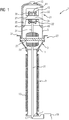
- Figure 1 shows a sectional view of a measuring transducer 1.
- the measuring transducer 1 is designed as a gas-insulated combined voltage and current transformer.
- the transducer 1 comprises a transducer housing 3 with a housing head 5, a housing base 7 and an insulator 9 running between the housing head 5 and the housing base 7 Housing head opening surrounds, constricted.
- the insulator 9 adjoins the housing head end 11.
- the insulator 9 is designed essentially as a tube which has insulator ribs 13 on its outside, which run in a ring around a longitudinal axis of the insulator 9.
- the housing base 7 closes an end of the insulator 9 facing away from the housing head 5.
- the transducer housing 3 is designed to be gas-tight for receiving an insulating gas such as sulfur hexafluoride.
- the housing head 5 has a pressure relief valve 15 through which insulating gas can be discharged from the transducer housing 3 when the pressure in the transducer housing 3 exceeds a pressure threshold value.
- a conductor bushing 17 is arranged on the housing base 7, through which electrical conductors are led from the interior of the transducer housing 3 to the outside.
- a terminal box 19 for contacting the conductors guided through the conductor bushing 17 is arranged on the conductor bushing 17.
- an active part unit 21 with a winding arrangement 22 according to the invention and a current converter unit 23 are arranged as a voltage converter, the current converter unit 23 being arranged between the active part unit 21 and the insulator 9.
- the active part unit 21 and the winding arrangement 22 are explained below with reference to FIG Figures 2 to 5 described in more detail.
- the current transformer unit 23 comprises a primary conductor 25 in the form of a busbar with primary conductor connections 27 arranged outside of the transducer housing 3 and a current transformer winding arrangement 29, known per se and therefore not shown in detail, with a secondary current transformer winding running in a ring around the primary conductor 25.
- a secondary transducer winding 41 of the winding arrangement 22 and the secondary current transformer winding of the current transformer winding arrangement 29 are each connected to connections of the terminal box 19 via connecting lines (not shown), the connecting lines through tubular shielding sleeves 31 arranged in the transducer housing 3 and through the conductor lead-through 17 to the terminal box 19 are led.
- FIGS. 2 and 3 show the active part unit 21 of the transducer 1. It shows Figure 2 a perspective view and Figure 3 shows a perspective sectional illustration of the active part unit 21.
- the active part unit 21 comprises a transducer core 33, a press frame 35 and the winding arrangement 22.
- the winding arrangement 22 comprises a wound tube 37, a primary first transducer winding 39, the secondary second transducer winding 41, a rim electrode 43 according to the invention and four anti-rotation devices 45.
- the transducer core 33 is designed as an annular laminated core made up of laminated laminations which are pressed together by the press frame 35.
- the press frame 35 is U-shaped with two legs running parallel to one another and a leg connection connecting the two legs.
- the press frame 35 consists of two press frame halves 35.1, 35.2, which each form one half of each leg and the leg connection and lie on different sides of a plane of symmetry in which the press frame halves 35.1, 35.2 abut one another.
- the leg ends of each leg are designed for fastening the press frame 35 in the housing head 5 of the transducer 1.
- each press frame half 35.1, 35.2 has a connection opening 47 at each leg end through which a connecting element, for example a screw, for fastening the leg end to a corresponding frame holder 49 of the housing head 5 (see Figure 1 ) to be led.
- Each clamping element 51 is rod-like and has at least one end passed through a press frame half 35.1, 35.2 onto which a screw nut 53 is screwed to press the press frame half 35.1, 35.2 onto the transducer core 33.
- the winding tube 37 surrounds a core section 34 of the transducer core 33, which runs between the legs of the press frame 35 and through frame recesses 55 in the press frame halves 35.1, 35.2.
- the winding tube 37 supports the primary transducer winding 39 surrounding a central portion of the winding tube 37, the rim electrode 43 surrounding the primary transducer winding 39, and the secondary transducer winding 41 surrounding the rim electrode 43.
- the rim electrode 43 has an electrode center portion 57, the is designed as a hollow circular cylinder, and two opposing shielding collars 59. Each shielding collar 59 forms one end of the rim electrode 43 and is designed to shield electrical fields from the central electrode section 57 outwardly by more than 180 degrees, preferably by more than 270 degrees.
- the rim electrode 43 consists of two identical electrode halves 43.1, 43.2 (see Figures 4 and 5 ), which each form one half of the electrode center section 57 and each shielding collar 59.
- the rotation locks 45 connect the winding tube 37 to the press frame 35 and prevent rotation of the winding tube 37 about its longitudinal axis.
- Each end of the winding tube 37 is connected to each of the two press frame halves 35.1, 35.2 by a respective anti-rotation lock 45, so that the winding tube 37 is connected to the press frame 35 by a total of four anti-rotation locks 45.
- Each anti-rotation device 45 connects the winding tube 37 to the press frame 35 by means of a curing compound in a manner not described in detail here.
- Figure 4 shows a perspective view of the winding arrangement 22 of the active part unit 21 formed by the winding tube 37, the transducer windings 39, 41 and the electrode halves 43.1, 43.2 of the rim electrode 43.
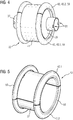
- FIG. 5 shows a perspective view of the rim electrode 43.
- the two electrode halves 43.1, 43.2 are identical and can be placed precisely against one another in a plane in which a longitudinal axis of the rim electrode 43 runs, so that they jointly form the electrode center section 57 and the two shielding collars 59.
- Each shielding collar 59 adjoins the central electrode section 57, the shielding collar 59 in the area directly adjoining the central electrode section 57 being initially bent inwardly opposite the central electrode section 57 and the shielding collar 59 subsequently being designed to be bent outward so that the shielding collar 59 has the shape a toroidal jacket, from which a strip extending annularly around the electrode center section 57 is cut out.
- the rim electrode 43 is made of a metallic material, for example aluminum, for shielding electrical fields.
Description
Die Erfindung betrifft eine Wicklungsanordnung eines Messwandlers und insbesondere eine Felgenelektrode einer derartigen Wicklungsanordnung.The invention relates to a winding arrangement of a measuring transducer and in particular a rim electrode of such a winding arrangement.
Genauer betrifft die Erfindung als Spannungswandler ausgebildete Messwandler zum Messen elektrischer Spannungen und/oder zum Schutz vor hohen elektrischen Spannungen sowie Messwandler, die eine Kombination derartiger Spannungswandler mit Stromwandlern zum Messen elektrischer Ströme und/oder zum Schutz vor hohen elektrischen Strömen sind.More precisely, the invention relates to measuring transducers designed as voltage converters for measuring electrical voltages and / or for protection against high electrical voltages, as well as measuring transducers which are a combination of such voltage converters with current converters for measuring electrical currents and / or for protecting against high electrical currents.
Derartige Messwandler, wie z. B. aus der
Der Erfindung liegt die Aufgabe zugrunde, eine verbesserte Elektrode einer Wicklungsanordnung eines Messwandlers, eine verbesserte Wicklungsanordnung eines Messwandlers und ein Verfahren zu deren Herstellung sowie einen verbesserten Messwandler anzugeben.The invention is based on the object of specifying an improved electrode of a winding arrangement of a measuring transducer, an improved winding arrangement of a measuring transducer and a method for their production as well as an improved measuring transducer.
Die Aufgabe wird erfindungsgemäß hinsichtlich der Elektrode durch die Merkmale des Anspruchs 1, hinsichtlich der Wicklungsanordnung durch die Merkmale des Anspruchs 5, hinsichtlich des Verfahrens durch die Merkmale des Anspruchs 7 und hinsichtlich des Messwandlers durch die Merkmale des Anspruchs 10 gelöst.The object is achieved according to the invention with regard to the electrode by the features of
Vorteilhafte Ausgestaltungen der Erfindung sind Gegenstand der Unteransprüche.Advantageous refinements of the invention are the subject matter of the subclaims.
Eine erfindungsgemäße Felgenelektrode einer Wicklungsanordnung eines Messwandlers umfasst einen hohlzylindrischen Elektrodenmittelabschnitt und zwei sich gegenüberliegende Enden der Felgenelektrode bildende ringförmige Abschirmkragen. Dabei schließt sich jeder Abschirmkragen an den Elektrodenmittelabschnitt an und ist gegenüber dem Elektrodenmittelabschnitt nach außen gebogen gestaltet.A rim electrode according to the invention of a winding arrangement of a measuring transducer comprises a hollow cylindrical electrode center section and two opposite ends of the rim electrode forming annular shielding collars. In this case, each shielding collar adjoins the central electrode section and is designed to be bent outward with respect to the central electrode section.
Die Felgenelektrode ermöglicht einerseits die Positionierung und Einbringung einer Messwandlerwicklung der Wicklungsanordnung durch Aufbringung der Messwandlerwicklung auf den Elektrodenmittelabschnitt und andererseits eine Abschirmung der Wicklungsanordnung vor elektrischen Feldern, insbesondere an den Enden der Wicklungsanordnung, durch die Abschirmkragen. Dadurch hat die Felgenelektrode zwei Funktionen, die bei herkömmlichen Wicklungsanordnungen durch separate Bauteile realisiert werden, nämlich durch eine Felge zum Positionierung und Einbringung einer Messwandlerwicklung und durch Abschirmelektroden zum Abschirmen elektrischer Felder. Dies verringert vorteilhaft die Anzahl der Komponenten der Wicklungsanordnung und dadurch auch die Bauteilkosten, und vereinfacht und verkürzt die Montage der Wicklungsanordnung.The rim electrode enables, on the one hand, the positioning and introduction of a transducer winding of the winding arrangement by applying the transducer winding to the central electrode section and, on the other hand, shielding the winding arrangement from electrical fields, in particular at the ends of the winding arrangement, by means of the shielding collar. As a result, the rim electrode has two functions that are implemented by separate components in conventional winding arrangements, namely by a rim for positioning and introducing a transducer winding and by shielding electrodes for shielding electrical fields. This advantageously reduces the number of components of the winding arrangement and thereby also the component costs, and simplifies and shortens the assembly of the winding arrangement.
Eine Ausgestaltung der Erfindung sieht vor, dass jeder Abschirmkragen gegenüber dem Elektrodenmittelabschnitt um mehr als 180 Grad nach außen gebogen und offen gestaltet ist.One embodiment of the invention provides that each shielding collar is bent outwards by more than 180 degrees with respect to the central electrode section and is designed to be open.
Durch die um mehr als 180 Grad nach außen gebogene Gestalt der Abschirmkragen wird deren Abschirmwirkung verbessert. Die offene Gestaltung der Abschirmkragen ermöglicht vorteilhaft das Einbringen einer Messwandlerwicklung der Wicklungsanordnung.The shielding effect is improved by the shape of the shielding collar, which is bent outwards by more than 180 degrees. The open design of the shielding collar advantageously enables a transducer winding to be introduced into the winding arrangement.
Die Erfindung sieht vor, dass die Felgenelektrode aus zwei Elektrodenhälften besteht, die jeweils eine Hälfte des Elektrodenmittelabschnitts und jedes Abschirmkragens bilden.The invention provides that the rim electrode consists of two electrode halves which each form one half of the central electrode section and each shielding collar.
Dies vereinfacht sowohl die Herstellung als auch die Montage der Felgenelektrode gegenüber einer einstückig ausgeführten Felgenelektrode.This simplifies both the production and the assembly of the rim electrode compared to a one-piece rim electrode.
Eine weitere Ausgestaltung der Erfindung sieht vor, dass die Felgenelektrode aus einem metallischen Werkstoff, beispielsweise aus Aluminium, gefertigt ist.Another embodiment of the invention provides that the rim electrode is made of a metallic material, for example aluminum.
Diese Werkstoffe ermöglichen vorteilhaft eine Abschirmwirkung der Abschirmkragen und eine stabile Ausführung des Elektrodenmittelabschnitts.These materials advantageously enable a shielding effect of the shielding collar and a stable design of the electrode center section.
Eine erfindungsgemäße Wicklungsanordnung eines Messwandlers umfasst eine erste Messwandlerwicklung, die um eine Wicklungsachse herum verläuft, eine erfindungsgemäße Felgenelektrode, die um die erste Messwandlerwicklung herum angeordnet ist, so dass eine Innenoberfläche des Elektrodenmittelabschnitts eine Außenoberfläche der ersten Messwandlerwicklung umgibt, und eine zweite Messwandlerwicklung, die um eine Außenoberfläche des Elektrodenmittelabschnitts herum verläuft. Optional weist die Wicklungsanordnung ferner ein Wickelrohr auf, um das herum die erste Messwandlerwicklung verläuft.A winding arrangement according to the invention of a measuring transducer comprises a first measuring transducer winding which runs around a winding axis, a rim electrode according to the invention which is arranged around the first measuring transducer winding so that an inner surface of the electrode center section surrounds an outer surface of the first measuring transducer winding, and a second measuring transducer winding which surrounds an outer surface of the electrode center portion extends around. Optionally, the winding arrangement also has a wound tube around which the first transducer winding runs.
Eine derartige Wicklungsanordnung hat durch die Ausführung mit einer erfindungsgemäßen Felgenelektrode die oben bereits genannten Vorteile. Ein Wickelrohr vereinfacht vorteilhaft die Positionierung und Montage der Wicklungsanordnung, insbesondere um einen Kernabschnitt eines Messwandlerkerns.Such a winding arrangement has the advantages already mentioned above due to the design with a rim electrode according to the invention. A winding tube advantageously simplifies the positioning and assembly of the winding arrangement, in particular around a core section of a transducer core.
Bei einem erfindungsgemäßen Verfahren zur Herstellung einer erfindungsgemäßen Wicklungsanordnung wird die Innenoberfläche des Elektrodenmittelabschnitts der Felgenelektrode stoffschlüssig mit der Außenoberfläche der ersten Messwandlerwicklung verbunden. Anschließend wird die zweite Messwandlerwicklung um die Außenoberfläche des Elektrodenmittelabschnitts der Felgenelektrode gelegt. Dabei wird die Innenoberfläche des Elektrodenmittelabschnitts beispielsweise mit einem Klebstoff stoffschlüssig mit der Außenoberfläche der ersten Messwandlerwicklung verbunden. Alternativ oder zusätzlich wird auf die Außenoberfläche der ersten Messwandlerwicklung oder/und auf die Innenoberfläche des Elektrodenmittelabschnitts ein Bindemittel aufgebracht und die Innenoberfläche des Elektrodenmittelabschnitts wird durch Erhitzen des Bindemittels mit der Außenoberfläche der ersten Messwandlerwicklung stoffschlüssig verbunden.In a method according to the invention for producing a winding arrangement according to the invention, the inner surface of the central electrode section of the rim electrode is materially bonded to the outer surface of the first transducer winding. The second transducer winding is then placed around the outer surface of the central electrode section of the rim electrode. The inner surface of the electrode center section is cohesively bonded to the outer surface of the electrode, for example with an adhesive first transducer winding connected. Alternatively or additionally, a binding agent is applied to the outer surface of the first transducer winding and / or to the inner surface of the electrode center section and the inner surface of the electrode center section is bonded to the outer surface of the first transducer winding by heating the binder.
Bei diesem Herstellungsverfahren brauchen insbesondere die beiden Elektrodenhälften einer zweiteilig ausgeführten Felgenelektrode nicht miteinander verbunden werden, da ihre Positionen durch die stoffschlüssige Verbindung mit der ersten Messwandlerwicklung fixiert werden.In this manufacturing process, the two electrode halves of a two-part rim electrode in particular do not need to be connected to one another, since their positions are fixed by the material connection with the first transducer winding.
Ein erfindungsgemäßer Messwandler weist eine erfindungsgemäße Wicklungsanordnung auf. Optional weist der Messwandler ferner einen Messwandlerkern mit einem Kernabschnitt, um den herum die Wicklungsanordnung angeordnet ist, auf.A measuring transducer according to the invention has a winding arrangement according to the invention. Optionally, the measuring transducer furthermore has a measuring transducer core with a core section around which the winding arrangement is arranged.
Ein derartiger Messwandler hat durch die Ausführung mit einer erfindungsgemäßen Wicklungsanordnung die oben bereits Vorteile.Such a transducer already has the advantages above due to the design with a winding arrangement according to the invention.
Die oben beschriebenen Eigenschaften, Merkmale und Vorteile dieser Erfindung sowie die Art und Weise, wie diese erreicht werden, werden klarer und deutlicher verständlich im Zusammenhang mit der folgenden Beschreibung von Ausführungsbeispielen, die im Zusammenhang mit den Zeichnungen näher erläutert werden. Dabei zeigen:
- FIG 1
- eine Schnittdarstellung eines Messwandlers,
- FIG 2
- eine perspektivische Darstellung einer Aktivteileinheit eines Messwandlers,
- FIG 3
- eine perspektivische Schnittdarstellung einer Aktivteileinheit eines Messwandlers,
- FIG 4
- eine perspektivische Darstellung einer Wicklungsanordnung einer Aktivteileinheit eines Messwandlers, und
- FIG 5
- eine perspektivische Darstellung einer Felgenelektrode.
- FIG 1
- a sectional view of a transducer,
- FIG 2
- a perspective view of an active part unit of a transducer,
- FIG 3
- a perspective sectional view of an active part unit of a transducer,
- FIG 4
- a perspective view of a winding arrangement of an active part unit of a transducer, and
- FIG 5
- a perspective view of a rim electrode.
Einander entsprechende Teile sind in allen Figuren mit den gleichen Bezugszeichen versehen.Corresponding parts are provided with the same reference symbols in all figures.
Der Messwandler 1 umfasst ein Messwandlergehäuse 3 mit einem Gehäusekopf 5, einem Gehäuseboden 7 und einem zwischen dem Gehäusekopf 5 und dem Gehäuseboden 7 verlaufenden Isolator 9. Der Gehäusekopf 5 ist als ein flaschenartiger Hohlkörper ausgebildet, der sich konisch zu einem ringförmigen Gehäusekopfende 11, das eine Gehäusekopföffnung umgibt, verengt. An das Gehäusekopfende 11 schließt sich der Isolator 9 an. Der Isolator 9 ist im Wesentlichen als ein Rohr ausgebildet, das an seiner Außenseite Isolatorrippen 13 aufweist, die ringförmig um eine Längsachse des Isolators 9 verlaufen. Der Gehäuseboden 7 verschließt ein von dem Gehäusekopf 5 abgewandtes Ende des Isolators 9. Das Messwandlergehäuse 3 ist zur Aufnahme eines Isoliergases wie beispielsweise Schwefelhexafluorid gasdicht ausgebildet. Der Gehäusekopf 5 weist ein Druckentlastungsventil 15 auf, durch das Isoliergas aus dem Messwandlergehäuse 3 abgeführt werden kann, wenn der Druck in dem Messwandlergehäuse 3 einen Druckschwellenwert überschreitet. An dem Gehäuseboden 7 ist eine Leiterdurchführung 17 angeordnet, durch die elektrische Leiter aus dem Innern des Messwandlergehäuses 3 nach außen geführt werden. An der Leiterdurchführung 17 ist ein Klemmenkasten 19 zum Kontaktieren der durch die Leiterdurchführung 17 geführten Leiter angeordnet. In dem Gehäusekopf 5 sind als Spannungswandler eine Aktivteileinheit 21 mit einer erfindungsgemäßen Wicklungsanordnung 22 und eine Stromwandlereinheit 23 angeordnet, wobei die Stromwandlereinheit 23 zwischen der Aktivteileinheit 21 und dem Isolator 9 angeordnet ist.The
Die Aktivteileinheit 21 und die Wicklungsanordnung 22 werden unten anhand der
Eine sekundäre Messwandlerwicklung 41 der Wicklungsanordnung 22 und die sekundäre Stromwandlerwicklung der Stromwandlerwicklungsanordnung 29 sind über (nicht dargestellte) Verbindungsleitungen jeweils mit Anschlüssen des Klemmenkastens 19 verbunden, wobei die Verbindungsleitungen durch in dem Messwandlergehäuse 3 angeordnete rohrartige Abschirmhülsen 31 und durch die Leiterdurchführung 17 zu dem Klemmenkasten 19 geführt sind.A secondary transducer winding 41 of the winding
Die
Die Aktivteileinheit 21 umfasst einen Messwandlerkern 33, einen Pressrahmen 35 und die Wicklungsanordnung 22. Die Wicklungsanordnung 22 umfasst ein Wickelrohr 37, eine primäre erste Messwandlerwicklung 39, die sekundäre zweite Messwandlerwicklung 41, eine erfindungsgemäße Felgenelektrode 43 und vier Verdrehsicherungen 45.The
Der Messwandlerkern 33 ist als ein ringförmiges Blechpaket ausgebildet, das aus übereinander geschichteten Blechlamellen besteht, die durch den Pressrahmen 35 aneinander gedrückt werden.The
Der Pressrahmen 35 ist U-förmig mit zwei parallel zueinander verlaufenden Schenkeln und einer die beiden Schenkel verbindenden Schenkelverbindung ausgebildet. Der Pressrahmen 35 besteht aus zwei Pressrahmenhälften 35.1, 35.2, die jeweils eine Hälfte jedes Schenkels und der Schenkelverbindung bilden und auf verschiedenen Seiten einer Symmetrieebene liegen, in der Pressrahmenhälften 35.1, 35.2 aneinander anliegen. Die Schenkelenden jedes Schenkels sind zur Befestigung des Pressrahmens 35 in dem Gehäusekopf 5 des Messwandlers 1 ausgebildet. In dem dargestellten Ausführungsbeispiel weist jede Pressrahmenhälfte 35.1, 35.2 dazu an jedem Schenkelende eine Verbindungsöffnung 47 auf, durch die ein Verbindungselement, beispielsweise eine Schraube, zur Befestigung des Schenkelendes an einer korrespondierenden Rahmenhalterung 49 des Gehäusekopfes 5 (siehe
Zur Befestigung des Pressrahmens 35 an dem Messwandlerkern 33 und zum Verspannen der Blechlamellen des Messwandlerkerns 33 sind mehrere Spannelemente 51 durch den Messwandlerkern 33 und die beiden Pressrahmenhälften 35.1, 35.2 geführt. Dabei ist jedes Spannelement 51 stabartig ausgebildet und weist wenigstens ein durch eine Pressrahmenhälfte 35.1, 35.2 geführtes Ende auf, auf das eine Schraubenmutter 53 zum Anpressen der Pressrahmenhälfte 35.1, 35.2 an den Messwandlerkern 33 geschraubt ist.To fasten the
Das Wickelrohr 37 umgibt einen Kernabschnitt 34 des Messwandlerkerns 33, der zwischen den Schenkeln des Pressrahmens 35 und durch Rahmenaussparungen 55 in den Pressrahmenhälften 35.1, 35.2 verläuft. Das Wickelrohr 37 trägt die primäre Messwandlerwicklung 39, die einen Mittelabschnitt des Wickelrohrs 37 umgibt, die Felgenelektrode 43, die die primäre Messwandlerwicklung 39 umgibt, und die sekundäre Messwandlerwicklung 41, die die Felgenelektrode 43 umgibt. Die Felgenelektrode 43 weist einen Elektrodenmittelabschnitt 57, der als ein hohler Kreiszylinder ausgebildet ist, und zwei sich gegenüber liegende Abschirmkragen 59 auf. Jeder Abschirmkragen 59 bildet ein Ende der Felgenelektrode 43 und ist zur Abschirmung elektrischer Felder gegenüber dem Elektrodenmittelabschnitt 57 nach außen um mehr als 180 Grad, vorzugsweise um mehr 270 Grad, umgebogen gestaltet. Dabei besteht die Felgenelektrode 43 aus zwei gleichartigen Elektrodenhälften 43.1, 43.2 (siehe
Die Verdrehsicherungen 45 verbinden das Wickelrohr 37 mit dem Pressrahmen 35 und verhindern eine Drehung des Wickelrohrs 37 um seine Längsachse. Dabei ist jedes Ende des Wickelrohrs 37 mit jeder der beiden Pressrahmenhälften 35.1, 35.2 durch jeweils eine Verdrehsicherung 45 verbunden, so dass das Wickelrohr 37 durch insgesamt vier Verdrehsicherungen 45 mit dem Pressrahmen 35 verbunden ist. Jede Verdrehsicherung 45 verbindet das Wickelrohr 37 mit dem Pressrahmen 35 durch eine Aushärtungsmasse in hier nicht näher beschriebener Weise.The rotation locks 45 connect the winding
Bei der Herstellung der Wicklungsanordnung 22 wird die Innenoberfläche des Elektrodenmittelabschnitts 57 der Felgenelektrode 43 stoffschlüssig mit der Außenoberfläche der ersten Messwandlerwicklung 39 verbunden. Dazu wird die Innenoberfläche des Elektrodenmittelabschnitts 57 mit einem Klebstoff stoffschlüssig mit der Außenoberfläche der ersten Messwandlerwicklung 39 verbunden. Alternativ oder zusätzlich wird auf die Außenoberfläche der ersten Messwandlerwicklung 49 oder/und auf die Innenoberfläche des Elektrodenmittelabschnitts 57 ein Bindemittel aufgebracht und die Innenoberfläche des Elektrodenmittelabschnitts 57 wird durch Erhitzen des Bindemittels mit der Außenoberfläche der ersten Messwandlerwicklung 39 stoffschlüssig verbunden. Anschließend wird die zweite Messwandlerwicklung 41 um die Außenoberfläche des Elektrodenmittelabschnitts 57 gelegt.During the manufacture of the winding
- 11
- MesswandlerTransducer
- 33
- MesswandlergehäuseTransducer housing
- 55
- GehäusekopfHousing head
- 77th
- GehäusebodenCase back
- 99
- Isolatorinsulator
- 1111
- GehäusekopfendeHousing head end
- 1313th
- IsolatorrippeIsolator rib
- 1515th
- DruckentlastungsventilPressure relief valve
- 1717th
- LeiterdurchführungConductor bushing
- 1919th
- KlemmenkastenTerminal box
- 2121
- AktivteileinheitActive part unit
- 2222nd
- WicklungsanordnungWinding arrangement
- 2323
- StromwandlereinheitCurrent transformer unit
- 2525th
- PrimärleiterPrimary conductor
- 2727
- PrimärleiteranschlussPrimary conductor connection
- 2929
- StromwandlerwicklungsanordnungCurrent transformer winding arrangement
- 3131
- AbschirmhülseShielding sleeve
- 3333
- MesswandlerkernTransducer core
- 3434
- KernabschnittCore section
- 3535
- PressrahmenPress frame
- 35.1, 35.235.1, 35.2
- PressrahmenhälftePress frame half
- 3737
- WickelrohrWinding tube
- 39, 4139, 41
- MesswandlerwicklungTransducer winding
- 4343
- FelgenelektrodeRim electrode
- 43.1, 43.243.1, 43.2
- ElektrodenhälfteElectrode half
- 4545
- VerdrehsicherungAnti-twist device
- 4747
- VerbindungsöffnungConnection opening
- 4949
- RahmenhalterungFrame bracket
- 5151
- SpannelementClamping element
- 5353
- SchraubenmutterScrew nut
- 5555
- RahmenaussparungFrame recess
- 5757
- ElektrodenmittelabschnittElectrode center section
- 5959
- AbschirmkragenShielding collar
Claims (11)
- Rim electrode (43) of a winding arrangement (22) of a transducer (1), the rim electrode (43) comprising- a hollow-cylindrical electrode middle section (57)- and two annular shielding collars (59) which form opposite ends of the rim electrode (43),- wherein each shielding collar (59) adjoins the electrode middle section (57) and is designed to be bent to the outside in relation to the electrode middle section (57),
characterized in that
the rim electrode (43) consists of two electrode halves (43.1, 43.2) which each form one half of the electrode middle section (57) and of each shielding collar (59). - Rim electrode (43) according to Claim 1,
characterized in that
each shielding collar (59) is designed to be open and bent to the outside through more than 180° in relation to the electrode middle section (57). - Rim electrode (43) according to either of the preceding claims,
characterized in that
the rim electrode (43) is manufactured from a metal material. - Rim electrode (43) according to one of the preceding claims,
characterized in that
the rim electrode (43) is manufactured from aluminum. - Winding arrangement (22) of a transducer (1), the winding arrangement (22) comprising- a first transducer winding (39) which runs around a winding axis,- a rim electrode (43) according to one of the preceding claims which is arranged around the first transducer winding (39), so that an inner surface of the electrode middle section (57) surrounds an outer surface of the first transducer winding (39),- and a second transducer winding (41) which runs around an outer surface of the electrode middle section (57).
- Winding arrangement (22) according to Claim 5,
characterized by
a winding tube (37) around which the first transducer winding (39) runs. - Method for producing a winding arrangement (22) according to Claim 5 or 6, wherein the inner surface of the electrode middle section (57) of the rim electrode (43) is cohesively connected to the outer surface of the first transducer winding (39), and the second transducer winding (41) is then placed around the outer surface of the electrode middle section (57) of the rim electrode (43).
- Method according to Claim 7,
characterized in that
the inner surface of the electrode middle section (57) is cohesively connected to the outer surface of the first transducer winding (39) using an adhesive. - Method according to Claim 7 or 8,
characterized in that a binding agent is applied to the outer surface of the first transducer winding (39) or/and to the inner surface of the electrode middle section (57), and the inner surface of the electrode middle section (57) is cohesively connected to the outer surface of the first transducer winding (39) by heating the binding agent. - Transducer (1) comprising a winding arrangement (22) according to Claim 5 or 6.
- Transducer (1) according to Claim 10,
characterized by
a transducer core (33) comprising a core section (34) around which the winding arrangement (22) is arranged.
Applications Claiming Priority (2)
| Application Number | Priority Date | Filing Date | Title |
|---|---|---|---|
| DE102015216860.3A DE102015216860A1 (en) | 2015-09-03 | 2015-09-03 | Rim electrode and winding arrangement of a transducer |
| PCT/EP2016/068499 WO2017036715A1 (en) | 2015-09-03 | 2016-08-03 | Rim electrode and winding arrangement of a transducer |
Publications (2)
| Publication Number | Publication Date |
|---|---|
| EP3320547A1 EP3320547A1 (en) | 2018-05-16 |
| EP3320547B1 true EP3320547B1 (en) | 2021-04-14 |
Family
ID=56618153
Family Applications (1)
| Application Number | Title | Priority Date | Filing Date |
|---|---|---|---|
| EP16750147.7A Active EP3320547B1 (en) | 2015-09-03 | 2016-08-03 | Rim electrode and winding arrangement of a transducer |
Country Status (5)
| Country | Link |
|---|---|
| EP (1) | EP3320547B1 (en) |
| CN (1) | CN107924753A (en) |
| DE (1) | DE102015216860A1 (en) |
| ES (1) | ES2877526T3 (en) |
| WO (1) | WO2017036715A1 (en) |
Families Citing this family (3)
| Publication number | Priority date | Publication date | Assignee | Title |
|---|---|---|---|---|
| DE102016216499B4 (en) * | 2016-09-01 | 2018-04-19 | Siemens Aktiengesellschaft | Voltage transformer unit with an active part housing |
| DE102019214368B4 (en) * | 2019-09-20 | 2023-02-02 | Siemens Energy Global GmbH & Co. KG | Instrument transformer arrangement with a voltage transformer and a current transformer |
| DE102020201100A1 (en) * | 2020-01-30 | 2021-08-05 | Siemens Aktiengesellschaft | Voltage converter |
Family Cites Families (12)
| Publication number | Priority date | Publication date | Assignee | Title |
|---|---|---|---|---|
| DE533273C (en) * | 1929-11-16 | 1931-09-11 | Koch & Sterzel Akt Ges | Measuring transformer set, consisting of an assembled current and voltage transformer |
| CH218921A (en) * | 1940-08-19 | 1942-01-15 | Bbc Brown Boveri & Cie | High voltage current transformer. |
| DE967656C (en) * | 1955-08-30 | 1957-12-05 | Koch & Sterzel Ag | Combined current and voltage converter |
| DE2325450A1 (en) * | 1973-05-17 | 1974-11-21 | Siemens Ag | SINGLE CONVERTER FOR HIGH VOLTAGE SWITCHGEAR |
| DE2452056B2 (en) * | 1974-11-02 | 1978-02-09 | Messwandler-Bau Gmbh, 8600 Bamberg | INDUCTIVE VOLTAGE CONVERTER FOR A METAL ENCLOSED HIGH VOLTAGE SWITCHGEAR FULLY INSULATED WITH INSULATING GAS |
| DE2524547C2 (en) * | 1975-05-30 | 1989-09-21 | Siemens AG, 1000 Berlin und 8000 München | Single-conductor transformer for metal-enclosed high-voltage switchgear |
| JPH0646611B2 (en) * | 1984-12-26 | 1994-06-15 | 日新電機株式会社 | Transformer |
| JPS61201410A (en) * | 1985-03-04 | 1986-09-06 | Toshiba Corp | Gas insulated voltage transformer |
| DE3737989C1 (en) * | 1987-11-09 | 1989-05-11 | Messwandler Bau Ag | High voltage converter |
| CH698970A1 (en) * | 2008-06-04 | 2009-12-15 | Trench Switzerland Ag | High-voltage transducer with flexible insulation. |
| CN103077811B (en) * | 2013-02-27 | 2015-07-08 | 江苏盛华电气有限公司 | Shield ring of high-voltage transformer winding and processing method thereof |
| CN103730247B (en) * | 2013-12-17 | 2016-04-20 | 国家电网公司 | A kind of full-shield high_voltage isolation type voltage transformer |
-
2015
- 2015-09-03 DE DE102015216860.3A patent/DE102015216860A1/en not_active Withdrawn
-
2016
- 2016-08-03 ES ES16750147T patent/ES2877526T3/en active Active
- 2016-08-03 EP EP16750147.7A patent/EP3320547B1/en active Active
- 2016-08-03 WO PCT/EP2016/068499 patent/WO2017036715A1/en active Application Filing
- 2016-08-03 CN CN201680051034.0A patent/CN107924753A/en active Pending
Non-Patent Citations (1)
| Title |
|---|
| None * |
Also Published As
| Publication number | Publication date |
|---|---|
| DE102015216860A1 (en) | 2017-03-09 |
| CN107924753A (en) | 2018-04-17 |
| EP3320547A1 (en) | 2018-05-16 |
| ES2877526T3 (en) | 2021-11-17 |
| WO2017036715A1 (en) | 2017-03-09 |
Similar Documents
| Publication | Publication Date | Title |
|---|---|---|
| DE102006008922B4 (en) | Electric shielding arrangement | |
| EP3320547B1 (en) | Rim electrode and winding arrangement of a transducer | |
| DE102004046134A1 (en) | Outdoor termination | |
| EP2620958B1 (en) | Shielding device for an electrically conductive connection element | |
| DE4240118C1 (en) | Execution, especially for high voltages with a special electrode holder | |
| EP2360804A1 (en) | Assembly for linking two energy cables | |
| DE2118176A1 (en) | Three-pole encapsulated high-voltage line | |
| EP2846336B1 (en) | Connection of at least four electrical conductors | |
| WO2011086033A1 (en) | High-voltage duct | |
| EP3320551B1 (en) | Active part unit of a measurement transducer, and measurement transducer | |
| EP3093938B1 (en) | High voltage implementation system | |
| DE19746313A1 (en) | Cable termination or cable sleeve with geometric field control | |
| EP3281214B1 (en) | Current transformer and switchgear having a current transformer | |
| DE3022070C2 (en) | Screen body for wound core legs of transformers, inductors and the like. | |
| EP3076409B1 (en) | Electrical connection between separated windings | |
| DE4234362C1 (en) | Electrical suppression coil with tension restraint - is provided by bead at component end of each terminal wire enclosed by shrink-fit sleeve | |
| EP3479387B1 (en) | Voltage transformer with active component housing | |
| EP2403087A1 (en) | Arrangement for connecting two paper-insulated high voltage cables | |
| EP3358690A1 (en) | Coupling sleeve | |
| EP3174160A1 (en) | Cover and method for covering a section of at least one conductor | |
| DE2513393C3 (en) | High voltage current transformer | |
| EP3490074B1 (en) | System for contacting a screen of a cable | |
| DE19938303C2 (en) | Device for connecting in particular tubular electrical conductors of an energy transmission system | |
| EP3266085B1 (en) | Field control element for end closures of cables for transmitting energy | |
| DE19623723A1 (en) | Gas-insulated conductor e.g. flexible cable with low-pressure SF6 filling |
Legal Events
| Date | Code | Title | Description |
|---|---|---|---|
| STAA | Information on the status of an ep patent application or granted ep patent |
Free format text: STATUS: THE INTERNATIONAL PUBLICATION HAS BEEN MADE |
|
| PUAI | Public reference made under article 153(3) epc to a published international application that has entered the european phase |
Free format text: ORIGINAL CODE: 0009012 |
|
| STAA | Information on the status of an ep patent application or granted ep patent |
Free format text: STATUS: REQUEST FOR EXAMINATION WAS MADE |
|
| 17P | Request for examination filed |
Effective date: 20180206 |
|
| AK | Designated contracting states |
Kind code of ref document: A1 Designated state(s): AL AT BE BG CH CY CZ DE DK EE ES FI FR GB GR HR HU IE IS IT LI LT LU LV MC MK MT NL NO PL PT RO RS SE SI SK SM TR |
|
| AX | Request for extension of the european patent |
Extension state: BA ME |
|
| DAV | Request for validation of the european patent (deleted) | ||
| DAX | Request for extension of the european patent (deleted) | ||
| GRAP | Despatch of communication of intention to grant a patent |
Free format text: ORIGINAL CODE: EPIDOSNIGR1 |
|
| STAA | Information on the status of an ep patent application or granted ep patent |
Free format text: STATUS: GRANT OF PATENT IS INTENDED |
|
| INTG | Intention to grant announced |
Effective date: 20201207 |
|
| RAP1 | Party data changed (applicant data changed or rights of an application transferred) |
Owner name: SIEMENS ENERGY GLOBAL GMBH & CO. KG |
|
| GRAS | Grant fee paid |
Free format text: ORIGINAL CODE: EPIDOSNIGR3 |
|
| GRAA | (expected) grant |
Free format text: ORIGINAL CODE: 0009210 |
|
| STAA | Information on the status of an ep patent application or granted ep patent |
Free format text: STATUS: THE PATENT HAS BEEN GRANTED |
|
| AK | Designated contracting states |
Kind code of ref document: B1 Designated state(s): AL AT BE BG CH CY CZ DE DK EE ES FI FR GB GR HR HU IE IS IT LI LT LU LV MC MK MT NL NO PL PT RO RS SE SI SK SM TR |
|
| REG | Reference to a national code |
Ref country code: GB Ref legal event code: FG4D Free format text: NOT ENGLISH |
|
| REG | Reference to a national code |
Ref country code: CH Ref legal event code: EP |
|
| REG | Reference to a national code |
Ref country code: DE Ref legal event code: R096 Ref document number: 502016012821 Country of ref document: DE |
|
| REG | Reference to a national code |
Ref country code: IE Ref legal event code: FG4D Free format text: LANGUAGE OF EP DOCUMENT: GERMAN |
|
| REG | Reference to a national code |
Ref country code: AT Ref legal event code: REF Ref document number: 1383168 Country of ref document: AT Kind code of ref document: T Effective date: 20210515 |
|
| REG | Reference to a national code |
Ref country code: SE Ref legal event code: TRGR |
|
| REG | Reference to a national code |
Ref country code: LT Ref legal event code: MG9D |
|
| REG | Reference to a national code |
Ref country code: NL Ref legal event code: MP Effective date: 20210414 |
|
| PG25 | Lapsed in a contracting state [announced via postgrant information from national office to epo] |
Ref country code: HR Free format text: LAPSE BECAUSE OF FAILURE TO SUBMIT A TRANSLATION OF THE DESCRIPTION OR TO PAY THE FEE WITHIN THE PRESCRIBED TIME-LIMIT Effective date: 20210414 Ref country code: BG Free format text: LAPSE BECAUSE OF FAILURE TO SUBMIT A TRANSLATION OF THE DESCRIPTION OR TO PAY THE FEE WITHIN THE PRESCRIBED TIME-LIMIT Effective date: 20210714 Ref country code: FI Free format text: LAPSE BECAUSE OF FAILURE TO SUBMIT A TRANSLATION OF THE DESCRIPTION OR TO PAY THE FEE WITHIN THE PRESCRIBED TIME-LIMIT Effective date: 20210414 Ref country code: NL Free format text: LAPSE BECAUSE OF FAILURE TO SUBMIT A TRANSLATION OF THE DESCRIPTION OR TO PAY THE FEE WITHIN THE PRESCRIBED TIME-LIMIT Effective date: 20210414 Ref country code: LT Free format text: LAPSE BECAUSE OF FAILURE TO SUBMIT A TRANSLATION OF THE DESCRIPTION OR TO PAY THE FEE WITHIN THE PRESCRIBED TIME-LIMIT Effective date: 20210414 |
|
| REG | Reference to a national code |
Ref country code: ES Ref legal event code: FG2A Ref document number: 2877526 Country of ref document: ES Kind code of ref document: T3 Effective date: 20211117 |
|
| PG25 | Lapsed in a contracting state [announced via postgrant information from national office to epo] |
Ref country code: RS Free format text: LAPSE BECAUSE OF FAILURE TO SUBMIT A TRANSLATION OF THE DESCRIPTION OR TO PAY THE FEE WITHIN THE PRESCRIBED TIME-LIMIT Effective date: 20210414 Ref country code: PT Free format text: LAPSE BECAUSE OF FAILURE TO SUBMIT A TRANSLATION OF THE DESCRIPTION OR TO PAY THE FEE WITHIN THE PRESCRIBED TIME-LIMIT Effective date: 20210816 Ref country code: PL Free format text: LAPSE BECAUSE OF FAILURE TO SUBMIT A TRANSLATION OF THE DESCRIPTION OR TO PAY THE FEE WITHIN THE PRESCRIBED TIME-LIMIT Effective date: 20210414 Ref country code: NO Free format text: LAPSE BECAUSE OF FAILURE TO SUBMIT A TRANSLATION OF THE DESCRIPTION OR TO PAY THE FEE WITHIN THE PRESCRIBED TIME-LIMIT Effective date: 20210714 Ref country code: GR Free format text: LAPSE BECAUSE OF FAILURE TO SUBMIT A TRANSLATION OF THE DESCRIPTION OR TO PAY THE FEE WITHIN THE PRESCRIBED TIME-LIMIT Effective date: 20210715 Ref country code: LV Free format text: LAPSE BECAUSE OF FAILURE TO SUBMIT A TRANSLATION OF THE DESCRIPTION OR TO PAY THE FEE WITHIN THE PRESCRIBED TIME-LIMIT Effective date: 20210414 Ref country code: IS Free format text: LAPSE BECAUSE OF FAILURE TO SUBMIT A TRANSLATION OF THE DESCRIPTION OR TO PAY THE FEE WITHIN THE PRESCRIBED TIME-LIMIT Effective date: 20210814 |
|
| REG | Reference to a national code |
Ref country code: DE Ref legal event code: R097 Ref document number: 502016012821 Country of ref document: DE |
|
| PG25 | Lapsed in a contracting state [announced via postgrant information from national office to epo] |
Ref country code: SK Free format text: LAPSE BECAUSE OF FAILURE TO SUBMIT A TRANSLATION OF THE DESCRIPTION OR TO PAY THE FEE WITHIN THE PRESCRIBED TIME-LIMIT Effective date: 20210414 Ref country code: SM Free format text: LAPSE BECAUSE OF FAILURE TO SUBMIT A TRANSLATION OF THE DESCRIPTION OR TO PAY THE FEE WITHIN THE PRESCRIBED TIME-LIMIT Effective date: 20210414 Ref country code: DK Free format text: LAPSE BECAUSE OF FAILURE TO SUBMIT A TRANSLATION OF THE DESCRIPTION OR TO PAY THE FEE WITHIN THE PRESCRIBED TIME-LIMIT Effective date: 20210414 Ref country code: EE Free format text: LAPSE BECAUSE OF FAILURE TO SUBMIT A TRANSLATION OF THE DESCRIPTION OR TO PAY THE FEE WITHIN THE PRESCRIBED TIME-LIMIT Effective date: 20210414 Ref country code: CZ Free format text: LAPSE BECAUSE OF FAILURE TO SUBMIT A TRANSLATION OF THE DESCRIPTION OR TO PAY THE FEE WITHIN THE PRESCRIBED TIME-LIMIT Effective date: 20210414 Ref country code: RO Free format text: LAPSE BECAUSE OF FAILURE TO SUBMIT A TRANSLATION OF THE DESCRIPTION OR TO PAY THE FEE WITHIN THE PRESCRIBED TIME-LIMIT Effective date: 20210414 |
|
| PLBE | No opposition filed within time limit |
Free format text: ORIGINAL CODE: 0009261 |
|
| STAA | Information on the status of an ep patent application or granted ep patent |
Free format text: STATUS: NO OPPOSITION FILED WITHIN TIME LIMIT |
|
| 26N | No opposition filed |
Effective date: 20220117 |
|
| PG25 | Lapsed in a contracting state [announced via postgrant information from national office to epo] |
Ref country code: MC Free format text: LAPSE BECAUSE OF FAILURE TO SUBMIT A TRANSLATION OF THE DESCRIPTION OR TO PAY THE FEE WITHIN THE PRESCRIBED TIME-LIMIT Effective date: 20210414 |
|
| REG | Reference to a national code |
Ref country code: BE Ref legal event code: MM Effective date: 20210831 |
|
| GBPC | Gb: european patent ceased through non-payment of renewal fee |
Effective date: 20210803 |
|
| PG25 | Lapsed in a contracting state [announced via postgrant information from national office to epo] |
Ref country code: IS Free format text: LAPSE BECAUSE OF FAILURE TO SUBMIT A TRANSLATION OF THE DESCRIPTION OR TO PAY THE FEE WITHIN THE PRESCRIBED TIME-LIMIT Effective date: 20210814 Ref country code: LU Free format text: LAPSE BECAUSE OF NON-PAYMENT OF DUE FEES Effective date: 20210803 Ref country code: AL Free format text: LAPSE BECAUSE OF FAILURE TO SUBMIT A TRANSLATION OF THE DESCRIPTION OR TO PAY THE FEE WITHIN THE PRESCRIBED TIME-LIMIT Effective date: 20210414 |
|
| PG25 | Lapsed in a contracting state [announced via postgrant information from national office to epo] |
Ref country code: IE Free format text: LAPSE BECAUSE OF NON-PAYMENT OF DUE FEES Effective date: 20210803 Ref country code: GB Free format text: LAPSE BECAUSE OF NON-PAYMENT OF DUE FEES Effective date: 20210803 Ref country code: FR Free format text: LAPSE BECAUSE OF NON-PAYMENT OF DUE FEES Effective date: 20210831 Ref country code: BE Free format text: LAPSE BECAUSE OF NON-PAYMENT OF DUE FEES Effective date: 20210831 |
|
| REG | Reference to a national code |
Ref country code: AT Ref legal event code: MM01 Ref document number: 1383168 Country of ref document: AT Kind code of ref document: T Effective date: 20210803 |
|
| PG25 | Lapsed in a contracting state [announced via postgrant information from national office to epo] |
Ref country code: AT Free format text: LAPSE BECAUSE OF NON-PAYMENT OF DUE FEES Effective date: 20210803 |
|
| PG25 | Lapsed in a contracting state [announced via postgrant information from national office to epo] |
Ref country code: HU Free format text: LAPSE BECAUSE OF FAILURE TO SUBMIT A TRANSLATION OF THE DESCRIPTION OR TO PAY THE FEE WITHIN THE PRESCRIBED TIME-LIMIT; INVALID AB INITIO Effective date: 20160803 |
|
| PG25 | Lapsed in a contracting state [announced via postgrant information from national office to epo] |
Ref country code: CY Free format text: LAPSE BECAUSE OF FAILURE TO SUBMIT A TRANSLATION OF THE DESCRIPTION OR TO PAY THE FEE WITHIN THE PRESCRIBED TIME-LIMIT Effective date: 20210414 |
|
| PGFP | Annual fee paid to national office [announced via postgrant information from national office to epo] |
Ref country code: IT Payment date: 20230822 Year of fee payment: 8 Ref country code: ES Payment date: 20230914 Year of fee payment: 8 Ref country code: CH Payment date: 20230902 Year of fee payment: 8 |
|
| PGFP | Annual fee paid to national office [announced via postgrant information from national office to epo] |
Ref country code: SE Payment date: 20230823 Year of fee payment: 8 Ref country code: DE Payment date: 20230828 Year of fee payment: 8 |