EP3319196A1 - Charging control circuit, charging device, charging system and charging control method - Google Patents
Charging control circuit, charging device, charging system and charging control method Download PDFInfo
- Publication number
- EP3319196A1 EP3319196A1 EP15896747.1A EP15896747A EP3319196A1 EP 3319196 A1 EP3319196 A1 EP 3319196A1 EP 15896747 A EP15896747 A EP 15896747A EP 3319196 A1 EP3319196 A1 EP 3319196A1
- Authority
- EP
- European Patent Office
- Prior art keywords
- unit
- charging
- switch
- power output
- rechargeable batteries
- Prior art date
- Legal status (The legal status is an assumption and is not a legal conclusion. Google has not performed a legal analysis and makes no representation as to the accuracy of the status listed.)
- Granted
Links
Images



Classifications
-
- H—ELECTRICITY
- H02—GENERATION; CONVERSION OR DISTRIBUTION OF ELECTRIC POWER
- H02J—ELECTRIC POWER NETWORKS; CIRCUIT ARRANGEMENTS OR SYSTEMS FOR SUPPLYING OR DISTRIBUTING ELECTRIC POWER; SYSTEMS FOR STORING ELECTRIC ENERGY
- H02J7/00—Circuit arrangements for charging or discharging batteries or for supplying loads from batteries
- H02J7/50—Circuit arrangements for charging or discharging batteries or for supplying loads from batteries acting upon multiple batteries simultaneously or sequentially
Definitions
- the present disclosure generally relates to the field of battery charging technologies, and in particular, to charging control circuits, charging devices, charging systems and charging control methods.
- portable mobile terminals, cameras, photographic apparatuses and other electronic devices are generally equipped with a plurality of rechargeable batteries.
- battery power When battery power is used up, it is necessary to use a charger to charge the plurality of batteries.
- a common charging manner on the market at present is connecting a plurality of rechargeable batteries in parallel, to uniformly charge a rechargeable battery pack in parallel connection.
- the manner has lots of shortcomings, for example, after the rechargeable batteries having different voltage values are connected in parallel, it may result in high voltage batteries discharging to low voltage batteries. Generally the discharge current may be very large, therefore it is easy to cause danger.
- a charger after the plurality of rechargeable batteries are connected in parallel, in the process of charging, it is likely that a charger first charges the low voltage batteries, because the batteries will be fully charged together at the same time, and if it is intended to use a battery already fully charged in the process of charging, the user has to wait for a longer time, which is not convenient for use by users.
- a charging control circuit including:
- the switch unit may be a relay switch; or a MOS transistor, wherein a source of the MOS transistor is electrically connected with the charging unit, a drain of the MOS transistor is electrically connected with the corresponding power output end, and a gate of the MOS transistor is electrically connected with the control unit; or the switch unit may be a NPN type triode, a collector is electrically connected with the charging unit, an emitter is electrically connected with the corresponding power output end, and a base is electrically connected with the control unit.
- control unit may be one of a Field-Programmable Gate Array (FPGA), a Micro-Controller Unit (MCU) with a control program embedded therein or a single chip computer.
- FPGA Field-Programmable Gate Array
- MCU Micro-Controller Unit
- the switching signal output by the mode switching unit may be implemented by means of hardware or software.
- the mode switching unit may include a button, to output the switching signal by operating the button; or the mode switching unit includes an automatic switching circuit, the automatic switching circuit being used to automatically output the switching signal after detecting a preset trigger condition.
- the charging control circuit may further include a voltage collection unit, the voltage collection unit being connected between the charging unit and the switch unit, and connected to the control unit; the voltage collection unit is used to collect voltage values of the rechargeable batteries, and the control unit, in accordance with the voltage values collected by the voltage collection unit, controls switch-on or switch-off of electrical connections between the plurality of power output ends and the charging unit through the switch unit.
- control unit controls the plurality of power output ends to be switched on with the charging unit one by one through the switch unit, to control the voltage collection unit to collect a battery voltage of each rechargeable battery.
- control unit controls the switch unit to, in accordance with an order of battery voltages from high to low, sequentially switch on the power output end which corresponds to the rechargeable battery with the maximum voltage value among the plurality of rechargeable batteries, and power off the other power output ends, so as to control the charging unit to sequentially charge the plurality of rechargeable batteries to a first preset value, and then switch on all the plurality of power output ends, to cause the charging unit to charge all the rechargeable batteries once again and charge the rechargeable batteries to a second preset value.
- control unit controls the plurality of power output ends to be switched on with the charging unit one by one through the switch unit, so as to make the voltage collection unit detect battery voltages of the plurality of rechargeable batteries one by one, and the control unit further controls the power output end, which corresponds to the rechargeable battery with the maximum voltage value among the battery voltages detected, to be switched on and the other power output ends to be powered off, to cause the charging unit to charge the rechargeable battery with the maximum battery voltage value to the first preset value.
- control unit controls the switch unit to, in accordance with an order of battery voltages of the rechargeable batteries from high to low, sequentially switch on the power output end which corresponds to the rechargeable battery with the maximum voltage value among the rechargeable batteries, and power off the other power output ends, so as to control the charging unit to sequentially charge the rechargeable batteries to a second preset value.
- control unit controls the plurality of power output ends to be switched on with the charging unit one by one through the switch unit, so as to make the voltage collection unit detect battery voltages of the plurality of rechargeable batteries one by one, and the control unit further controls the power output end, which corresponds to the rechargeable battery with the maximum voltage value among the plurality of battery voltages detected, to be switched on and the other power output ends to be powered off, to cause the charging unit to sequentially charge the rechargeable battery with the maximum battery voltage value to the second preset value.
- control unit controls the corresponding power output end to be powered off when a charging voltage of the rechargeable battery reaches the second preset value.
- a charging device comprising a housing and a charging control circuit mounted in the housing, wherein the charging control circuit includes:
- the switch unit is a relay switch; or a MOS transistor, wherein a source of the MOS transistor is electrically connected with the charging unit, a drain of the MOS transistor is electrically connected with the corresponding power output end, and a gate of the MOS transistor is electrically connected with the control unit; or the switch unit is a NPN type triode, a collector is electrically connected with the charging unit, an emitter is electrically connected with the corresponding power output end, and a base is electrically connected with the control unit.
- control unit is one of a Field-Programmable Gate Array (FPGA), a Micro-Controller Unit (MCU) with a control program embedded therein or a single chip computer.
- FPGA Field-Programmable Gate Array
- MCU Micro-Controller Unit
- the switching signal output by the mode switching unit is implemented by means of hardware or software.
- the mode switching unit includes a button, to output the switching signal by operating the button; or the mode switching unit includes an automatic switching circuit, the automatic switching circuit being used to automatically output the switching signal after detecting a preset trigger condition.
- the charging control circuit further includes a voltage collection unit, the voltage collection unit being connected between the charging unit and the switch unit, and connected to the control unit; the voltage collection unit is used to collect voltage values of the rechargeable batteries, and the control unit, in accordance with the voltage values collected by the voltage collection unit, controls switch-on or switch-off of electrical connections between the plurality of power output ends and the charging unit through the switch unit.
- control unit controls the plurality of power output ends to be switched on with the charging unit one by one through the switch unit, to control the voltage collection unit to collect a battery voltage of each rechargeable battery.
- control unit controls the switch unit to, in accordance with an order of battery voltages from high to low, sequentially switch on the power output end which corresponds to the rechargeable battery with the maximum voltage value among the plurality of rechargeable batteries, and power off the other power output ends, so as to control the charging unit to sequentially charge the plurality of rechargeable batteries to a first preset value, and then switch on all the plurality of power output ends, to cause the charging unit to charge all the rechargeable batteries once again and charge the rechargeable batteries to a second preset value.
- control unit controls the plurality of power output ends to be switched on with the charging unit one by one through the switch unit, so as to make the voltage collection unit detect battery voltages of the plurality of rechargeable batteries one by one, and the control unit further controls the power output end, which corresponds to the rechargeable battery with the maximum voltage value in the battery voltages detected, to be switched on and the other power output ends to be powered off, to cause the charging unit to charge the rechargeable battery with the maximum battery voltage value to the first preset value.
- control unit controls the switch unit to, in accordance with an order of battery voltages of the rechargeable batteries from high to low, sequentially switch on the power output end which corresponds to the rechargeable battery with the maximum voltage value among the rechargeable batteries, and power off the other power output ends, so as to control the charging unit to sequentially charge the rechargeable batteries to a second preset value.
- control unit controls the plurality of power output ends to be switched on with the charging unit one by one through the switch unit, so as to make the voltage collection unit detect battery voltages of the plurality of rechargeable batteries one by one, and the control unit further controls the power output end, which corresponds to the rechargeable battery with the maximum voltage value among the plurality of battery voltages detected, to be switched on and the other power output ends to be powered off, to cause the charging unit to sequentially charge the rechargeable battery with the maximum battery voltage value to the second preset value.
- control unit controls the corresponding power output end to be powered off when a charging voltage of the rechargeable battery reaches the second preset value.
- a charging system including a plurality of rechargeable batteries and a charging control circuit used to charge the plurality of rechargeable batteries, wherein the charging control circuit includes:
- the switch unit is a relay switch; or a MOS transistor, wherein a source of the MOS transistor is electrically connected with the charging unit, a drain of the MOS transistor is electrically connected with the corresponding power output end, and a gate of the MOS transistor is electrically connected with the control unit; or the switch unit is a NPN type triode, a collector is electrically connected with the charging unit, an emitter is electrically connected with the corresponding power output end, and a base is electrically connected with the control unit.
- control unit is one of a Field-Programmable Gate Array (FPGA), a Micro-Controller Unit (MCU) with a control program embedded therein or a single chip computer.
- FPGA Field-Programmable Gate Array
- MCU Micro-Controller Unit
- the switching signal output by the mode switching unit is implemented by means of hardware or software.
- the mode switching unit includes a button, to output the switching signal by operating the button; or the mode switching unit includes an automatic switching circuit, the automatic switching circuit being used to automatically output the switching signal after detecting a preset trigger condition.
- the charging control circuit further includes a voltage collection unit, the voltage collection unit being connected between the charging unit and the switch unit, and connected to the control unit; the voltage collection unit is used to collect voltage values of the rechargeable batteries, and the control unit, in accordance with the voltage values collected by the voltage collection unit, controls switch-on or switch-off of electrical connections between the plurality of power output ends and the charging unit through the switch unit.
- control unit controls the plurality of power output ends to be switched on with the charging unit one by one through the switch unit, to control the voltage collection unit to collect a battery voltage of each rechargeable battery.
- control unit controls the switch unit to, in accordance with an order of battery voltages from high to low, sequentially switch on the power output end which corresponds to the rechargeable battery with the maximum voltage value among the plurality of rechargeable batteries, and power off the other power output ends, so as to control the charging unit to sequentially charge the plurality of rechargeable batteries to a first preset value, and then switch on all the plurality of power output ends, to cause the charging unit to charge all the rechargeable batteries once again and charge the rechargeable batteries to a second preset value.
- control unit controls the plurality of power output ends to be switched on with the charging unit one by one through the switch unit, so as to make the voltage collection unit detect battery voltages of the plurality of rechargeable batteries one by one, and the control unit further controls the power output end, which corresponds to the rechargeable battery with the maximum voltage value in the battery voltages detected, to be switched on and the other power output ends to be powered off, to cause the charging unit to charge the rechargeable battery with the maximum battery voltage value to the first preset value.
- control unit controls the switch unit to, in accordance with an order of battery voltages of the rechargeable batteries from high to low, sequentially switch on the power output end which corresponds to the rechargeable battery with the maximum voltage value among the rechargeable batteries, and power off the other power output ends, so as to control the charging unit to sequentially charge the rechargeable batteries to a second preset value.
- control unit controls the plurality of power output ends to be switched on with the charging unit one by one through the switch unit, so as to make the voltage collection unit detect battery voltages of the plurality of rechargeable batteries one by one, and the control unit further controls the power output end, which corresponds to the rechargeable battery with the maximum voltage value among the plurality of battery voltages detected, to be switched on and the other power output ends to be powered off, to cause the charging unit to sequentially charge the rechargeable battery with the maximum battery voltage value to the second preset value.
- control unit controls the corresponding power output end to be powered off when a charging voltage of the rechargeable battery reaches the second preset value.
- a charging control method including:
- the switching signal is triggered by operating a button; or the switching signal is automatically triggered after a preset trigger condition is detected.
- the step of switching to a first charging mode in accordance with the switching signal comprises:
- the step of sequentially charging the plurality of rechargeable batteries to a first preset value in accordance with an order of battery voltages of the rechargeable batteries from high to low includes:
- the step of switching to a second charging mode in accordance with the switching signal includes:
- a charging control circuit including:
- the switch unit is a relay switch; or a MOS transistor, wherein a source of the MOS transistor is electrically connected with the charging unit, a drain of the MOS transistor is electrically connected with the corresponding power output end, and a gate of the MOS transistor is electrically connected with the control unit; or the switch unit is a NPN type triode, a collector is electrically connected with the charging unit, an emitter is electrically connected with the corresponding power output end, and a base is electrically connected with the control unit.
- control unit is one of a Field-Programmable Gate Array (FPGA), a Micro-Controller Unit (MCU) with a control program embedded therein or a single chip computer.
- FPGA Field-Programmable Gate Array
- MCU Micro-Controller Unit
- the charging control circuit further includes a voltage collection unit, the voltage collection unit being connected between the charging unit and the switch unit and connected to the control unit; the voltage collection unit is used to collect voltage values of the rechargeable batteries, and the control unit, in accordance with the voltage values collected by the voltage collection unit, controls switch-on or switch-off of electrical connections between the plurality of power output ends and the charging unit through the switch unit.
- control unit controls the plurality of power output ends to be switched on with the charging unit one by one through the switch unit, to control the voltage collection unit to collect a battery voltage of each rechargeable battery.
- the charging unit sequentially charges the plurality of rechargeable batteries to the first preset value by means of constant current charging.
- the charging unit charges the plurality of rechargeable batteries from the first preset value to the second preset value by means of constant voltage charging.
- control unit controls the corresponding power output ends to be powered off when charging voltages of the rechargeable batteries reach the second preset value.
- a charging device comprising a housing and a charging control circuit mounted in the housing, wherein the charging control circuit comprises:
- the switch unit is a relay switch; or a MOS transistor, wherein a source of the MOS transistor is electrically connected with the charging unit, a drain of the MOS transistor is electrically connected with the corresponding power output end, and a gate of the MOS transistor is electrically connected with the control unit; or the switch unit is a NPN type triode, a collector is electrically connected with the charging unit, an emitter is electrically connected with the corresponding power output end, and a base is electrically connected with the control unit.
- control unit is one of a Field-Programmable Gate Array (FPGA), a Micro-Controller Unit (MCU) with a control program embedded therein or a single chip computer.
- FPGA Field-Programmable Gate Array
- MCU Micro-Controller Unit
- the charging device further includes a voltage collection unit, the voltage collection unit being connected between the charging unit and the switch unit and connected to the control unit; the voltage collection unit is used to collect voltage values of the rechargeable batteries, and the control unit, in accordance with the voltage values collected by the voltage collection unit, controls switch-on or switch-off of electrical connection between the plurality of power output ends and the charging unit through the switch unit.
- control unit controls the plurality of power output ends to be switched on with the charging unit one by one through the switch unit, to control the voltage collection unit to collect a battery voltage of each rechargeable battery.
- the charging unit sequentially charges the plurality of rechargeable batteries to the first preset value by means of constant current charging.
- the charging unit charges the plurality of rechargeable batteries from the first preset value to the second preset value by means of constant voltage charging.
- control unit controls the corresponding power output ends to be powered off when charging voltages of the rechargeable batteries reach the second preset value.
- a charging system wherein the charging system includes a plurality of rechargeable batteries and a charging control circuit used to charge the plurality of rechargeable batteries, wherein the charging control circuit includes:
- the switch unit is a relay switch; or a MOS transistor, wherein a source of the MOS transistor is electrically connected with the charging unit, a drain of the MOS transistor is electrically connected with the corresponding power output end, and a gate of the MOS transistor is electrically connected with the control unit; or the switch unit is a NPN type triode, a collector is electrically connected with the charging unit, an emitter is electrically connected with the corresponding power output end, and a base is electrically connected with the control unit.
- control unit is one of a Field-Programmable Gate Array (FPGA), a Micro-Controller Unit (MCU) with a control program embedded therein or a single chip computer.
- FPGA Field-Programmable Gate Array
- MCU Micro-Controller Unit
- the charging system further includes a voltage collection unit, the voltage collection unit being connected between the charging unit and the switch unit and connected to the control unit; the voltage collection unit is used to collect voltage values of the rechargeable batteries, and the control unit, in accordance with the voltage values collected by the voltage collection unit, controls switch-on or switch-off of the switch unit.
- control unit controls the plurality of power output ends to be switched on with the charging unit one by one through the switch unit, to control the voltage collection unit to collect a battery voltage of each rechargeable battery.
- the charging unit sequentially charges the plurality of rechargeable batteries to the first preset value by means of constant current charging.
- the charging unit charges the plurality of rechargeable batteries from the first preset value to the second preset value by means of constant voltage charging.
- control unit controls the corresponding power output ends to be powered off when charging voltages of the rechargeable batteries reach the second preset value.
- a charging control method including:
- the plurality of rechargeable batteries are sequentially charged to the first preset value by means of constant current charging.
- the plurality of rechargeable batteries are charged from the first preset value to the second preset value by means of constant voltage charging.
- a plurality of rechargeable batteries are charged by using two charging modes, and the two charging modes can be switched in accordance with user demands, that is, when it is necessary to prevent high voltage batteries from high current discharge to low voltage batteries so as to effectively protect the rechargeable batteries, it is possible to switch to the first charging mode; moreover, when it is necessary to fully charge one rechargeable battery within the shortest time so as to meet users' need, it is possible to switch to the second charging mode, which makes the charging control circuits more practical.
- Charging control circuit 100 Power output end 10 Charging unit 20 Control unit 30 Switch unit 40 Voltage collection unit 50 Mode switching unit 70 Rechargeable battery 200 Movable device 300 Power device 301 Electronic Speed Control (ESC) 303 Motor 305 Propeller 307
- one element when one element is referred to as “electrically connect” another element, it may be directly on another assembly or it is also possible that there is an element between them.
- it When one element is considered to “electrically connect” another element, it may be a contact connection, for example, it may be a wire connection manner, and it may also be a non-contact connection, for example, it may be a non-contact coupling manner.
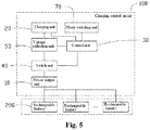
- an embodiment of the present disclosure provides a charging control circuit 100, used to charge a plurality of rechargeable batteries 200.
- the charging control circuit 100 includes a plurality of power output ends 10, a charging unit 20, a control unit 30, a plurality of switch units 40 corresponding to the power output ends 10 in a one to one manner and a voltage collection unit 50.
- the plurality of power output ends 10 are connected in parallel with each other and each power output end 10 is electrically connected with the charging unit 20, and one of the switch units 40 is further connected between each power output end 10 and the charging unit 20.
- the charging unit 20 may include a power input end, an AC/DC conversion circuit and/or a DC conversion circuit and other circuit modules, used to be electrically connected to an external power supply, and process the external power supply into a corresponding charging voltage which is then output to the power output end 10.
- the control unit 30 may be a Field-Programmable Gate Array (FPGA), a Micro-Controller Unit (MCU) with a control program embedded therein or a single chip computer or the like.
- the control unit 30 may be electrically connected with the plurality of switch units 40 through a control bus, used to output corresponding switch signals to the switch units 40.
- the switch units 40 receive the switch signals sent by the control unit 30, and switch on or switch off electrical connections between the charging unit 20 and the corresponding power output ends 10 in accordance with the switch signals, to cause the charging unit 20 to charge the rechargeable batteries 200 electrically connected to the power output ends 10 through the switch units 40 switched on and the corresponding power output ends 10.
- the switch unit 40 may be a Metal Oxide Semiconductor Field Effect Transistors (MOS transistors), or a relay or other electronic switches.
- MOS transistors Metal Oxide Semiconductor Field Effect Transistors
- the operation manner of the switch unit 40 is described by taking that the switch unit 40 is a MOS transistor as an example, a source of the MOS transistor is connected with the charging unit 20, a drain of the MOS transistor is connected with the corresponding power output end 10, and a gate of the MOS transistor is connected with the control unit 30 through the control bus.
- the control unit 30 sends a corresponding switch signal to the gate of the MOS transistor, for example, a high level signal or a low level signal, so as to control switch-on or switch-off of the MOS transistor.
- the charging unit 20 may charge the rechargeable batteries 200 through the MOS transistor switched on and the corresponding power output end 10.
- the switch unit 40 may also be a NPN type triode or other electronic switches.
- a base of the NPN type triode is connected with the charging unit 30 through the control bus, a collector is electrically connected with the charging unit 20, and an emitter is electrically connected with the corresponding power output end 10.
- the voltage collection unit 50 is electrically connected between the charging unit 20 and the switch unit 40 and electrically connected to the control unit 30.
- the voltage collection unit 50 is used to collect a voltage of each rechargeable battery 200, and transmit the collected voltage of each rechargeable battery 200 to the control unit 30.
- the voltage collected by the voltage collection unit 50 is an output voltage of the charging unit 20.
- the voltage collected by the voltage collection unit 50 is a battery voltage of the rechargeable battery 200 connected to the power output end 10 which corresponds to the switch unit 40 in an on state.
- the control unit 30 controls the switch units 40 to be switched on one by one, to control the voltage collection unit 50 to detect battery voltages of the rechargeable batteries 200 connected to the plurality of power output ends 10 respectively.
- the control unit 30 further controls switch-on and switch-off of the switch units 40 in accordance with the voltages collected by the voltage collection unit 50, so as to switch on or switch off the electrical connections between the charging unit 20 and the corresponding power output ends 10.
- the charging control circuit 100 may further include a mode switching unit 70.
- the mode switching unit 70 is electrically connected with the control unit 30.
- the mode switching unit 70 is used to output a switching signal, for example, a high level signal or a low level signal, to control the charging control circuit 100 to switch between a first charging mode and a second charging mode.
- a switching signal for example, a high level signal or a low level signal
- the control unit 30 operates in the first charging mode.
- the control unit 30 receives the low level signal sent by the mode switching unit 70
- the control unit 30 switches to the second charging mode.
- the switching signal output by the mode switching unit 70 may be implemented by means of hardware or software.
- the mode switching unit 70 includes a button. In this way, when the button is pressed down, the mode switching unit 70 outputs a high level signal to the control unit 30, to control the control unit 30 to switch to the first charging mode. When the button is not pressed down, the mode switching unit 70 outputs a low level signal, to control the control unit 30 to switch to the second charging mode.
- the mode switching unit 70 may also include an automatic switching circuit, the automatic switching circuit being used to automatically output a corresponding high level signal and a low level signal after detecting a preset trigger condition, to switch an operation mode of the charging control circuit 100.
- the charging control circuit 100 may also be set as that, when the mode switching unit 70 does not output any switching signal to the control unit 30, the charging control circuit 100 maintains the existing charging mode, for example, the first charging mode or the second charging mode, however, once the control unit 30 receives a switching signal output by the mode switching unit 70, switching between charging modes is performed, for example, switching from the first charging mode to the second charging mode or switching from the second charging mode to the first charging mode.
- control unit 30 controls the switch units 40 to be switched on one by one, that is, controls the plurality of power output ends 10 to be switched on with the charging unit 20 one by one, so that the voltage collection unit 50 can detect battery voltages of the rechargeable batteries 200 connected onto the plurality of power output ends 10 one by one.
- the control unit 30 further controls the switch unit 40, which corresponds to the rechargeable battery 200 with the maximum voltage value in the battery voltages detected, to be switched on and the other switch units 40 to be powered off, to control the power output end 10, which corresponds to the rechargeable battery 200 with the maximum voltage value in the battery voltages detected, to be switched on and the other power output ends 10 to be powered off, so as to cause the charging unit 20 to first charge the rechargeable battery 200 with the maximum battery voltage value.
- the voltage collection unit 50 detects battery voltages of the remaining rechargeable batteries 200 one by one.
- the control unit 30 further controls the switch unit 40, which corresponds to the rechargeable battery 200 with the maximum voltage value in the remaining rechargeable batteries 200, to be switched on and the other switch units 40 to be switched off, so as to cause the charging unit 20 to charge the rechargeable battery 200 with the maximum voltage value in the remaining rechargeable batteries 200 and charge the rechargeable battery 200 to the first preset value.
- the rest may be deduced by analogy; the control unit 30 controls the charging unit 20 to, in accordance with an order of the battery voltages of the rechargeable batteries 200 from high to low, sequentially charge the plurality of rechargeable batteries 200 all to the first preset value.
- the control unit 30 controls the plurality of switch units 40 to be all switched on, to cause the charging unit 20 to charge all the rechargeable batteries 200 once again and charge the rechargeable batteries 200 to a second preset value.
- the charging control circuit 100 first charges all the rechargeable batteries 200 to the first preset value respectively in accordance with an order of the battery voltages from high to low, and then charges all the rechargeable batteries 200 at the same time, that is, performs parallel charging.
- the plurality of rechargeable batteries 200 are charged at the same time, battery voltage values of the rechargeable batteries 200 are kept consistent, that is, all are the first preset value, therefore, high current discharge from high voltage batteries to low voltage batteries may be avoided, which can achieve an aim of effectively protecting the rechargeable batteries 200, and also shorten charging time of the whole system.
- the charging unit 20 can sequentially charge the plurality of rechargeable batteries 200 to the first preset value by means of constant current charging, and then sequentially charge the plurality of rechargeable batteries 200 from the first preset value to the second preset value by means of constant voltage charging.
- the control unit 30 controls the switch units 40 to be switched on one by one, that is, controls the plurality of power output ends 10 to be switched on with the charging unit 20 one by one, so that the voltage collection unit 50 can detect battery voltages of the rechargeable batteries 200 connected onto the plurality of power output ends 10 one by one.
- the control unit 30 further controls the switch unit 40, which corresponds to the rechargeable battery 200 with the maximum voltage value in the battery voltages detected, to be switched on and the other switch units 40 to be switched off, to control the power output end 10, which corresponds to the rechargeable battery 200 with the maximum voltage value in the battery voltages detected, to be switched on and the other power output ends 10 to be powered off, so as to cause the charging unit 20 to first charge the rechargeable battery 200 with the maximum voltage value and directly charge the rechargeable battery 200 to the second preset value.
- the voltage collection unit 50 detects battery voltages of the remaining rechargeable batteries 200 one by one.
- the control unit 30 further controls the switch unit 40, which corresponds to the rechargeable battery 200 with the maximum voltage value in the remaining rechargeable batteries 200, to be switched on and the other switch units 40 to be switched off, so as to cause the charging unit 20 to charge the rechargeable battery 200 with the maximum battery voltage value in the remaining rechargeable batteries 200 and directly charge the rechargeable battery 200 to the second preset value.
- the rest may be deduced by analogy; the control unit 30 sequentially charges the plurality of rechargeable batteries 200 by detecting battery voltages of the plurality of rechargeable batteries 200 and in accordance with an order of the battery voltages from high to low.
- the charging control circuit 100 may charge the rechargeable battery 200 with the maximum voltage value, and thus one rechargeable battery 200 can be fully charged within the shortest time, to meet use by a user.
- the first preset value is less than the second preset value
- the second preset value may be a rated output voltage value of the rechargeable battery 200 or a voltage value slightly greater than a rated output voltage of the rechargeable battery 200, for example, it may be 1.2 times the rated output voltage value of the rechargeable battery 200.
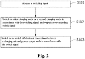
- a charging control method of the charging control circuit 100 provided in an implementation manner of the present disclosure includes the following steps:
- the control unit 30 in the charging control circuit 100 is electrically connected to the mode switching unit 70.
- the mode switching unit 70 is used to output the switching signal, for example, a high level signal or a low level signal, to control the charging control circuit 100 to switch between a first charging mode and a second charging mode.
- the control unit 30 receives the high level signal sent by the mode switching unit 70
- the control unit 30 operates in the first charging mode.
- the control unit 30 receives the low level signal sent by the mode switching unit 70
- the control unit 30 switches to the second charging mode.
- the switching signal output by the mode switching unit 70 may be implemented by means of hardware or software.
- the mode switching unit 70 includes a button.
- the control unit 30 may receive a high level signal sent by the mode switching unit 70, and the control unit 30 switches to the first charging mode.
- the control unit 30 receives a low level signal sent by the mode switching unit 70, and the control unit 30 switches to the second charging mode.
- the mode switching unit 70 may also include an automatic switching circuit, the automatic switching circuit being used to automatically output a corresponding high level signal and a low level signal after detecting a preset trigger condition, to switch an operation mode of the charging control circuit 100.
- S103 Electrical connections between the charging unit 20 and the power output ends 10 are switched on or switched off in accordance with the switch signal.
- the charging control circuit 100 further includes switch units 40, the switch units 40 being electrically connected between the charging unit 20 and the corresponding power output ends 10, and by switching on or switching off the switch units 40, electrical connections between the charging unit 20 and the power output ends 10 are switched on or switched off.
- the charging control circuit 100 may further include a voltage collection unit 50, and the control unit 30 controls the switch units 40 to be switched on one by one, that is, controls the plurality of power output ends 10 to be switched on with the charging unit 20 one by one, to control the voltage collection unit 50 to acquire a battery voltage of each rechargeable battery 200 and control switch-on or switch-off of the switch units 40 in accordance with the collected voltage values.
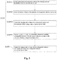
- the S102 when switching is performed to switch to the first charging mode in accordance with the switching signal, the S102 includes:
- S104 may include:
- the charging unit 20 may sequentially charge the plurality of rechargeable batteries 200 to the first preset value by means of constant current charging, and then sequentially charge the plurality of rechargeable batteries 200 from the first preset value to the second preset value by means of constant voltage charging.
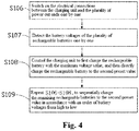
- the method may include:
- the first preset value is less than the second preset value
- the second preset value may be a rated output voltage value of the rechargeable battery 200 or a voltage value slightly greater than a rated output voltage of the rechargeable battery 200, for example, it may be 1.2 times the rated output voltage value of the rechargeable battery 200.
- the switch unit 40 may also be a switch chip integrated with multiple switches, and the power output end 10 may be a parallel port. Therefore, the number of the switch units 40 and the number of the power output ends 10 both can be reduced to one, and it is only necessary to respectively connect respective ports of the power output end 10 to respective switches of the switch unit 40.
- the aforementioned charging control circuit 100 may be mounted in a housing (not shown), and then form a charging device jointly with the housing.
- the charging device may form a charging system jointly with the plurality of rechargeable batteries 200.
- the charging system may be applied to a movable device 300.
- the movable device 300 may be a vehicle, a ship or the like.
- the movable device 300 may further include a power device 301.
- the charging system may be electrically connected with the power device 301, and used to provide electric energy for the power device 301.
- the movable device 300 is an unmanned aerial vehicle.
- the power device 301 includes an Electronic Speed Control (ESC) 303, a motor 305 and a propeller 307.
- the ESC 303 is electrically connected to the motor 305, and used to control a rotational speed of the motor 305.
- the propeller 307 is mounted on the motor 305, and used to, under the driving of the motor 305, drive the unmanned aerial vehicle 300 to fly.
- the charging system is electrically connected to the ESC 303, used to provide electric energy for the power device 301.
Landscapes
- Engineering & Computer Science (AREA)
- Power Engineering (AREA)
- Charge And Discharge Circuits For Batteries Or The Like (AREA)
- Secondary Cells (AREA)
Abstract
Description
- The present disclosure generally relates to the field of battery charging technologies, and in particular, to charging control circuits, charging devices, charging systems and charging control methods.
- At present, portable mobile terminals, cameras, photographic apparatuses and other electronic devices are generally equipped with a plurality of rechargeable batteries. When battery power is used up, it is necessary to use a charger to charge the plurality of batteries.
- A common charging manner on the market at present is connecting a plurality of rechargeable batteries in parallel, to uniformly charge a rechargeable battery pack in parallel connection. However, the manner has lots of shortcomings, for example, after the rechargeable batteries having different voltage values are connected in parallel, it may result in high voltage batteries discharging to low voltage batteries. Generally the discharge current may be very large, therefore it is easy to cause danger. In addition, after the plurality of rechargeable batteries are connected in parallel, in the process of charging, it is likely that a charger first charges the low voltage batteries, because the batteries will be fully charged together at the same time, and if it is intended to use a battery already fully charged in the process of charging, the user has to wait for a longer time, which is not convenient for use by users.
- In view of the aforementioned contents, it is necessary to provide more convenient charging control circuits, charging devices, charging systems and charging control methods.
- A charging control circuit, including:
- a charging unit;
- a plurality of power output ends, respectively used to connect with a plurality of rechargeable batteries and charge the plurality of rechargeable batteries;
- a switch unit, wherein the switch unit is connected between the charging unit and the plurality of power output ends;
- a control unit electrically connected with the switch unit; and
- a mode switching unit electrically connected with the control unit;
- wherein the control unit switches to a first charging mode or a second charging mode in accordance with a switching signal sent by the mode switching unit, and outputs a corresponding switch signal to the switch unit; and the switch unit switches on or switches off electrical connections between the charging unit and the plurality of power output ends in accordance with the switch signal.
- Further, the switch unit may be a relay switch;
or
a MOS transistor, wherein a source of the MOS transistor is electrically connected with the charging unit, a drain of the MOS transistor is electrically connected with the corresponding power output end, and a gate of the MOS transistor is electrically connected with the control unit;
or
the switch unit may be a NPN type triode, a collector is electrically connected with the charging unit, an emitter is electrically connected with the corresponding power output end, and a base is electrically connected with the control unit. - Further, the control unit may be one of a Field-Programmable Gate Array (FPGA), a Micro-Controller Unit (MCU) with a control program embedded therein or a single chip computer.
- Further, the switching signal output by the mode switching unit may be implemented by means of hardware or software.
- Further, the mode switching unit may include a button, to output the switching signal by operating the button;
or
the mode switching unit includes an automatic switching circuit, the automatic switching circuit being used to automatically output the switching signal after detecting a preset trigger condition. - Further, the charging control circuit may further include a voltage collection unit, the voltage collection unit being connected between the charging unit and the switch unit, and connected to the control unit; the voltage collection unit is used to collect voltage values of the rechargeable batteries, and the control unit, in accordance with the voltage values collected by the voltage collection unit, controls switch-on or switch-off of electrical connections between the plurality of power output ends and the charging unit through the switch unit.
- Further, the control unit controls the plurality of power output ends to be switched on with the charging unit one by one through the switch unit, to control the voltage collection unit to collect a battery voltage of each rechargeable battery.
- Further, when the control unit switches to the first charging mode, the control unit controls the switch unit to, in accordance with an order of battery voltages from high to low, sequentially switch on the power output end which corresponds to the rechargeable battery with the maximum voltage value among the plurality of rechargeable batteries, and power off the other power output ends, so as to control the charging unit to sequentially charge the plurality of rechargeable batteries to a first preset value, and then switch on all the plurality of power output ends, to cause the charging unit to charge all the rechargeable batteries once again and charge the rechargeable batteries to a second preset value.
- Further, the control unit controls the plurality of power output ends to be switched on with the charging unit one by one through the switch unit, so as to make the voltage collection unit detect battery voltages of the plurality of rechargeable batteries one by one, and the control unit further controls the power output end, which corresponds to the rechargeable battery with the maximum voltage value among the battery voltages detected, to be switched on and the other power output ends to be powered off, to cause the charging unit to charge the rechargeable battery with the maximum battery voltage value to the first preset value.
- Further, when the control unit switches to the second charging mode, the control unit controls the switch unit to, in accordance with an order of battery voltages of the rechargeable batteries from high to low, sequentially switch on the power output end which corresponds to the rechargeable battery with the maximum voltage value among the rechargeable batteries, and power off the other power output ends, so as to control the charging unit to sequentially charge the rechargeable batteries to a second preset value.
- Further, the control unit controls the plurality of power output ends to be switched on with the charging unit one by one through the switch unit, so as to make the voltage collection unit detect battery voltages of the plurality of rechargeable batteries one by one, and the control unit further controls the power output end, which corresponds to the rechargeable battery with the maximum voltage value among the plurality of battery voltages detected, to be switched on and the other power output ends to be powered off, to cause the charging unit to sequentially charge the rechargeable battery with the maximum battery voltage value to the second preset value.
- Further, the control unit controls the corresponding power output end to be powered off when a charging voltage of the rechargeable battery reaches the second preset value.
- A charging device, comprising a housing and a charging control circuit mounted in the housing, wherein the charging control circuit includes:
- a charging unit;
- a plurality of power output ends, respectively used to connect with a plurality of rechargeable batteries to be charged, and charge the plurality of rechargeable batteries;
- a switch unit, wherein the switch unit is connected between the charging unit and the plurality of power output ends;
- a control unit electrically connected with the switch unit; and
- a mode switching unit electrically connected with the control unit;
- wherein the control unit switches to a first charging mode or a second charging mode in accordance with a switching signal sent by the mode switching unit, and outputs a corresponding switch signal to the switch unit; and the switch unit switches on or switches off electrical connections between the charging unit and the plurality of power output ends in accordance with the switch signal.
- Further, the switch unit is a relay switch;
or
a MOS transistor, wherein a source of the MOS transistor is electrically connected with the charging unit, a drain of the MOS transistor is electrically connected with the corresponding power output end, and a gate of the MOS transistor is electrically connected with the control unit;
or
the switch unit is a NPN type triode, a collector is electrically connected with the charging unit, an emitter is electrically connected with the corresponding power output end, and a base is electrically connected with the control unit. - Further, the control unit is one of a Field-Programmable Gate Array (FPGA), a Micro-Controller Unit (MCU) with a control program embedded therein or a single chip computer.
- Further, the switching signal output by the mode switching unit is implemented by means of hardware or software.
- Further, the mode switching unit includes a button, to output the switching signal by operating the button;
or
the mode switching unit includes an automatic switching circuit, the automatic switching circuit being used to automatically output the switching signal after detecting a preset trigger condition. - Further, the charging control circuit further includes a voltage collection unit, the voltage collection unit being connected between the charging unit and the switch unit, and connected to the control unit; the voltage collection unit is used to collect voltage values of the rechargeable batteries, and the control unit, in accordance with the voltage values collected by the voltage collection unit, controls switch-on or switch-off of electrical connections between the plurality of power output ends and the charging unit through the switch unit.
- Further, the control unit controls the plurality of power output ends to be switched on with the charging unit one by one through the switch unit, to control the voltage collection unit to collect a battery voltage of each rechargeable battery.
- Further, when the control unit switches to the first charging mode, the control unit controls the switch unit to, in accordance with an order of battery voltages from high to low, sequentially switch on the power output end which corresponds to the rechargeable battery with the maximum voltage value among the plurality of rechargeable batteries, and power off the other power output ends, so as to control the charging unit to sequentially charge the plurality of rechargeable batteries to a first preset value, and then switch on all the plurality of power output ends, to cause the charging unit to charge all the rechargeable batteries once again and charge the rechargeable batteries to a second preset value.
- Further, the control unit controls the plurality of power output ends to be switched on with the charging unit one by one through the switch unit, so as to make the voltage collection unit detect battery voltages of the plurality of rechargeable batteries one by one, and the control unit further controls the power output end, which corresponds to the rechargeable battery with the maximum voltage value in the battery voltages detected, to be switched on and the other power output ends to be powered off, to cause the charging unit to charge the rechargeable battery with the maximum battery voltage value to the first preset value.
- Further, when the control unit switches to the second charging mode, the control unit controls the switch unit to, in accordance with an order of battery voltages of the rechargeable batteries from high to low, sequentially switch on the power output end which corresponds to the rechargeable battery with the maximum voltage value among the rechargeable batteries, and power off the other power output ends, so as to control the charging unit to sequentially charge the rechargeable batteries to a second preset value.
- Further, the control unit controls the plurality of power output ends to be switched on with the charging unit one by one through the switch unit, so as to make the voltage collection unit detect battery voltages of the plurality of rechargeable batteries one by one, and the control unit further controls the power output end, which corresponds to the rechargeable battery with the maximum voltage value among the plurality of battery voltages detected, to be switched on and the other power output ends to be powered off, to cause the charging unit to sequentially charge the rechargeable battery with the maximum battery voltage value to the second preset value.
- Further, the control unit controls the corresponding power output end to be powered off when a charging voltage of the rechargeable battery reaches the second preset value.
- A charging system, including a plurality of rechargeable batteries and a charging control circuit used to charge the plurality of rechargeable batteries, wherein the charging control circuit includes:
- a charging unit;
- a plurality of power output ends, respectively used to connect with the plurality of rechargeable batteries and charge the plurality of rechargeable batteries;
- a switch unit, wherein the switch unit is connected between the charging unit and the plurality of power output ends;
- a control unit electrically connected with the switch unit; and
- a mode switching unit electrically connected with the control unit;
- wherein the control unit switches to a first charging mode or a second charging mode in accordance with a switching signal sent by the mode switching unit, and outputs a corresponding switch signal to the switch unit; and the switch unit switches on or switches off electrical connections between the charging unit and the plurality of power output ends in accordance with the switch signal.
- Further, the switch unit is a relay switch;
or
a MOS transistor, wherein a source of the MOS transistor is electrically connected with the charging unit, a drain of the MOS transistor is electrically connected with the corresponding power output end, and a gate of the MOS transistor is electrically connected with the control unit;
or
the switch unit is a NPN type triode, a collector is electrically connected with the charging unit, an emitter is electrically connected with the corresponding power output end, and a base is electrically connected with the control unit. - Further, the control unit is one of a Field-Programmable Gate Array (FPGA), a Micro-Controller Unit (MCU) with a control program embedded therein or a single chip computer.
- Further, the switching signal output by the mode switching unit is implemented by means of hardware or software.
- Further, the mode switching unit includes a button, to output the switching signal by operating the button;
or
the mode switching unit includes an automatic switching circuit, the automatic switching circuit being used to automatically output the switching signal after detecting a preset trigger condition. - Further, the charging control circuit further includes a voltage collection unit, the voltage collection unit being connected between the charging unit and the switch unit, and connected to the control unit; the voltage collection unit is used to collect voltage values of the rechargeable batteries, and the control unit, in accordance with the voltage values collected by the voltage collection unit, controls switch-on or switch-off of electrical connections between the plurality of power output ends and the charging unit through the switch unit.
- Further, the control unit controls the plurality of power output ends to be switched on with the charging unit one by one through the switch unit, to control the voltage collection unit to collect a battery voltage of each rechargeable battery.
- Further, when the control unit switches to the first charging mode, the control unit controls the switch unit to, in accordance with an order of battery voltages from high to low, sequentially switch on the power output end which corresponds to the rechargeable battery with the maximum voltage value among the plurality of rechargeable batteries, and power off the other power output ends, so as to control the charging unit to sequentially charge the plurality of rechargeable batteries to a first preset value, and then switch on all the plurality of power output ends, to cause the charging unit to charge all the rechargeable batteries once again and charge the rechargeable batteries to a second preset value.
- Further, the control unit controls the plurality of power output ends to be switched on with the charging unit one by one through the switch unit, so as to make the voltage collection unit detect battery voltages of the plurality of rechargeable batteries one by one, and the control unit further controls the power output end, which corresponds to the rechargeable battery with the maximum voltage value in the battery voltages detected, to be switched on and the other power output ends to be powered off, to cause the charging unit to charge the rechargeable battery with the maximum battery voltage value to the first preset value.
- Further, when the control unit switches to the second charging mode, the control unit controls the switch unit to, in accordance with an order of battery voltages of the rechargeable batteries from high to low, sequentially switch on the power output end which corresponds to the rechargeable battery with the maximum voltage value among the rechargeable batteries, and power off the other power output ends, so as to control the charging unit to sequentially charge the rechargeable batteries to a second preset value.
- Further, the control unit controls the plurality of power output ends to be switched on with the charging unit one by one through the switch unit, so as to make the voltage collection unit detect battery voltages of the plurality of rechargeable batteries one by one, and the control unit further controls the power output end, which corresponds to the rechargeable battery with the maximum voltage value among the plurality of battery voltages detected, to be switched on and the other power output ends to be powered off, to cause the charging unit to sequentially charge the rechargeable battery with the maximum battery voltage value to the second preset value.
- Further, the control unit controls the corresponding power output end to be powered off when a charging voltage of the rechargeable battery reaches the second preset value.
- A charging control method, including:
- acquiring a switching signal;
- switching to a first charging mode or a second charging mode in accordance with the switching signal, and outputting a corresponding switch signal; and
- switching on or switching off electrical connections between a charging unit and a plurality of power output ends in accordance with the switch signal, wherein the plurality of power output ends are used to connect with a plurality of rechargeable batteries respectively, and the charging unit charges the plurality of rechargeable batteries through the plurality of power output ends.
- Further, the switching signal is triggered by operating a button;
or
the switching signal is automatically triggered after a preset trigger condition is detected. - Further, the step of switching to a first charging mode in accordance with the switching signal comprises:
- sequentially charging the plurality of rechargeable batteries to a first preset value in accordance with an order of battery voltages of the rechargeable batteries from high to low; and
- controlling the charging unit to charge all the rechargeable batteries once again and charge the rechargeable batteries to a second preset value.
- Further, the step of sequentially charging the plurality of rechargeable batteries to a first preset value in accordance with an order of battery voltages of the rechargeable batteries from high to low includes:
- (a) switching on the electrical connections between the charging unit and the plurality of power out ends one by one;
- (b) detecting the battery voltages of the plurality of rechargeable batteries one by one;
- (c) controlling the charging unit to charge the rechargeable battery with the maximum battery voltage value to the first preset value; and
- Further, the step of switching to a second charging mode in accordance with the switching signal includes:
- (d) switching on the electrical connections between the charging unit and the plurality of power out ends one by one;
- (e) detecting the battery voltages of the plurality of rechargeable batteries one by one;
- (f) controlling the charging unit to first charge the rechargeable battery with the maximum voltage value, and then directly charge the rechargeable battery to a second preset value; and
- A charging control circuit, including:
- a charging unit;
- a plurality of power output ends, respectively used to connect with a plurality of rechargeable batteries and charge the plurality of rechargeable batteries;
- a switch unit, wherein the switch unit is connected between the charging unit and the plurality of power output ends; and
- a control unit electrically connected with the switch unit;
- wherein the control unit controls switch-on and switch-off of electrical connections between the charging unit and the plurality of power output ends through the switch unit, to cause the charging unit to sequentially charge the plurality of rechargeable batteries to a first preset value in accordance with an order of battery voltages of the rechargeable batteries from high to low, then charge all the rechargeable batteries once again, and charge the rechargeable batteries to a second preset value.
- Further, the switch unit is a relay switch;
or
a MOS transistor, wherein a source of the MOS transistor is electrically connected with the charging unit, a drain of the MOS transistor is electrically connected with the corresponding power output end, and a gate of the MOS transistor is electrically connected with the control unit;
or
the switch unit is a NPN type triode, a collector is electrically connected with the charging unit, an emitter is electrically connected with the corresponding power output end, and a base is electrically connected with the control unit. - Further, the control unit is one of a Field-Programmable Gate Array (FPGA), a Micro-Controller Unit (MCU) with a control program embedded therein or a single chip computer.
- Further, the charging control circuit further includes a voltage collection unit, the voltage collection unit being connected between the charging unit and the switch unit and connected to the control unit; the voltage collection unit is used to collect voltage values of the rechargeable batteries, and the control unit, in accordance with the voltage values collected by the voltage collection unit, controls switch-on or switch-off of electrical connections between the plurality of power output ends and the charging unit through the switch unit.
- Further, the control unit controls the plurality of power output ends to be switched on with the charging unit one by one through the switch unit, to control the voltage collection unit to collect a battery voltage of each rechargeable battery.
- Further, the charging unit sequentially charges the plurality of rechargeable batteries to the first preset value by means of constant current charging.
- Further, the charging unit charges the plurality of rechargeable batteries from the first preset value to the second preset value by means of constant voltage charging.
- Further, the control unit controls the corresponding power output ends to be powered off when charging voltages of the rechargeable batteries reach the second preset value.
- A charging device, comprising a housing and a charging control circuit mounted in the housing, wherein the charging control circuit comprises:
- a charging unit;
- a plurality of power output ends, respectively used to connect with a plurality of rechargeable batteries and charge the plurality of rechargeable batteries;
- a switch unit, wherein the switch unit is connected between the charging unit and the plurality of power output ends; and
- a control unit electrically connected with the switch unit;
- wherein the control unit controls switch-on and switch-off of electrical connections between the charging unit and the plurality of power output ends through the switch unit, to cause the charging unit to sequentially charge the plurality of rechargeable batteries to a first preset value in accordance with an order of battery voltages of the rechargeable batteries from high to low, then charge all the rechargeable batteries once again, and charge the rechargeable batteries to a second preset value.
- Further, the switch unit is a relay switch;
or
a MOS transistor, wherein a source of the MOS transistor is electrically connected with the charging unit, a drain of the MOS transistor is electrically connected with the corresponding power output end, and a gate of the MOS transistor is electrically connected with the control unit;
or
the switch unit is a NPN type triode, a collector is electrically connected with the charging unit, an emitter is electrically connected with the corresponding power output end, and a base is electrically connected with the control unit. - Further, the control unit is one of a Field-Programmable Gate Array (FPGA), a Micro-Controller Unit (MCU) with a control program embedded therein or a single chip computer.
- Further, the charging device further includes a voltage collection unit, the voltage collection unit being connected between the charging unit and the switch unit and connected to the control unit; the voltage collection unit is used to collect voltage values of the rechargeable batteries, and the control unit, in accordance with the voltage values collected by the voltage collection unit, controls switch-on or switch-off of electrical connection between the plurality of power output ends and the charging unit through the switch unit.
- Further, the control unit controls the plurality of power output ends to be switched on with the charging unit one by one through the switch unit, to control the voltage collection unit to collect a battery voltage of each rechargeable battery.
- Further, the charging unit sequentially charges the plurality of rechargeable batteries to the first preset value by means of constant current charging.
- Further, the charging unit charges the plurality of rechargeable batteries from the first preset value to the second preset value by means of constant voltage charging.
- Further, the control unit controls the corresponding power output ends to be powered off when charging voltages of the rechargeable batteries reach the second preset value.
- A charging system, wherein the charging system includes a plurality of rechargeable batteries and a charging control circuit used to charge the plurality of rechargeable batteries, wherein the charging control circuit includes:
- a charging unit;
- a plurality of power output ends, respectively used to connect with a plurality of rechargeable batteries and charge the plurality of rechargeable batteries;
- a switch unit, wherein the switch unit is connected between the charging unit and the plurality of power output ends; and
- a control unit electrically connected with the switch unit;
- wherein the control unit controls switch-on and switch-off of electrical connections between the charging unit and the plurality of power output ends through the switch unit, to cause the charging unit to sequentially charge the plurality of rechargeable batteries to a first preset value in accordance with an order of battery voltages of the rechargeable batteries from high to low, then charge all the rechargeable batteries once again, and charge the rechargeable batteries to a second preset value.
- Further, the switch unit is a relay switch;
or
a MOS transistor, wherein a source of the MOS transistor is electrically connected with the charging unit, a drain of the MOS transistor is electrically connected with the corresponding power output end, and a gate of the MOS transistor is electrically connected with the control unit;
or
the switch unit is a NPN type triode, a collector is electrically connected with the charging unit, an emitter is electrically connected with the corresponding power output end, and a base is electrically connected with the control unit. - Further, the control unit is one of a Field-Programmable Gate Array (FPGA), a Micro-Controller Unit (MCU) with a control program embedded therein or a single chip computer.
- Further, the charging system further includes a voltage collection unit, the voltage collection unit being connected between the charging unit and the switch unit and connected to the control unit; the voltage collection unit is used to collect voltage values of the rechargeable batteries, and the control unit, in accordance with the voltage values collected by the voltage collection unit, controls switch-on or switch-off of the switch unit.
- Further, the control unit controls the plurality of power output ends to be switched on with the charging unit one by one through the switch unit, to control the voltage collection unit to collect a battery voltage of each rechargeable battery.
- Further, the charging unit sequentially charges the plurality of rechargeable batteries to the first preset value by means of constant current charging.
- Further, the charging unit charges the plurality of rechargeable batteries from the first preset value to the second preset value by means of constant voltage charging.
- Further, the control unit controls the corresponding power output ends to be powered off when charging voltages of the rechargeable batteries reach the second preset value.
- A charging control method, including:
- sequentially charging a plurality of rechargeable batteries to a first preset value in accordance with an order of battery voltages of the rechargeable batteries from high to low; and
- controlling a charging unit to charge all the rechargeable batteries once again and charge the rechargeable batteries to a second preset value.
- Further, the plurality of rechargeable batteries are sequentially charged to the first preset value by means of constant current charging.
- Further, the plurality of rechargeable batteries are charged from the first preset value to the second preset value by means of constant voltage charging.
- Further, when charging voltages of the rechargeable batteries reach the second preset value, corresponding power output ends are controlled to be powered off.
- According to the aforementioned charging control circuits, charging devices, charging systems and charging control methods, a plurality of rechargeable batteries are charged by using two charging modes, and the two charging modes can be switched in accordance with user demands, that is, when it is necessary to prevent high voltage batteries from high current discharge to low voltage batteries so as to effectively protect the rechargeable batteries, it is possible to switch to the first charging mode; moreover, when it is necessary to fully charge one rechargeable battery within the shortest time so as to meet users' need, it is possible to switch to the second charging mode, which makes the charging control circuits more practical.
-
-
Fig. 1 is one functional module diagram of a charging control circuit according to an embodiment of the present disclosure. -
Fig. 2 is a schematic flow chart of a charging control method according to an embodiment of the present disclosure. -
Fig. 3 is a schematic flow chart illustrating the charging control circuit shown inFig. 1 switching to a first charging mode. -
Fig. 4 is a schematic flow chart illustrating the charging control circuit shown inFig. 1 switching to a second charging mode. -
Fig. 5 is another functional module diagram of a charging control circuit according to an embodiment of the present disclosure. -
Fig. 6 is one schematic application diagram of a charging control circuit according to an embodiment of the present disclosure. -
Fig. 7 is another schematic application diagram of a charging control circuit according to an embodiment of the present disclosure. -
Charging control circuit 100 Power output end 10 Charging unit 20 Control unit 30 Switch unit 40 Voltage collection unit 50 Mode switching unit 70 Rechargeable battery 200 Movable device 300 Power device 301 Electronic Speed Control (ESC) 303 Motor 305 Propeller 307 - The embodiments of the present disclosure will be clearly described below with reference to the accompanying drawings in the embodiments of the present disclosure. Apparently, the described embodiments are merely some of the embodiments of the present disclosure rather than all of the embodiments. All other embodiments obtained by a person of ordinary skill in the art based on the embodiments of the present disclosure without creative efforts shall fall within the protection scope of the present disclosure.
- It should be noted that when one element is referred to as "electrically connect" another element, it may be directly on another assembly or it is also possible that there is an element between them. When one element is considered to "electrically connect" another element, it may be a contact connection, for example, it may be a wire connection manner, and it may also be a non-contact connection, for example, it may be a non-contact coupling manner.
- Unless otherwise defined, all the technical and scientific terms used herein are the same as the meanings generally understood by persons skilled in the technical field of the present disclosure. Herein, the terms used in the specification of the present disclosure are intended to describe specific embodiments, instead of limiting the present disclosure. The term "and/or" used herein includes any combination and all combinations of one or more related items listed.
- Some implementation manners of the present disclosure are described below in detail with reference to the accompanying drawings. In the event of no conflict, embodiments described below and features in the embodiments can be combined with each other.
- Referring to
Fig. 1 , an embodiment of the present disclosure provides a chargingcontrol circuit 100, used to charge a plurality ofrechargeable batteries 200. The chargingcontrol circuit 100 includes a plurality of power output ends 10, a chargingunit 20, acontrol unit 30, a plurality ofswitch units 40 corresponding to the power output ends 10 in a one to one manner and avoltage collection unit 50. - The plurality of power output ends 10 are connected in parallel with each other and each
power output end 10 is electrically connected with the chargingunit 20, and one of theswitch units 40 is further connected between eachpower output end 10 and the chargingunit 20. - The charging
unit 20 may include a power input end, an AC/DC conversion circuit and/or a DC conversion circuit and other circuit modules, used to be electrically connected to an external power supply, and process the external power supply into a corresponding charging voltage which is then output to thepower output end 10. - The
control unit 30 may be a Field-Programmable Gate Array (FPGA), a Micro-Controller Unit (MCU) with a control program embedded therein or a single chip computer or the like. Thecontrol unit 30 may be electrically connected with the plurality ofswitch units 40 through a control bus, used to output corresponding switch signals to theswitch units 40. Theswitch units 40 receive the switch signals sent by thecontrol unit 30, and switch on or switch off electrical connections between the chargingunit 20 and the corresponding power output ends 10 in accordance with the switch signals, to cause the chargingunit 20 to charge therechargeable batteries 200 electrically connected to the power output ends 10 through theswitch units 40 switched on and the corresponding power output ends 10. - The
switch unit 40 may be a Metal Oxide Semiconductor Field Effect Transistors (MOS transistors), or a relay or other electronic switches. In this implementation manner, the operation manner of theswitch unit 40 is described by taking that theswitch unit 40 is a MOS transistor as an example, a source of the MOS transistor is connected with the chargingunit 20, a drain of the MOS transistor is connected with the correspondingpower output end 10, and a gate of the MOS transistor is connected with thecontrol unit 30 through the control bus. Thecontrol unit 30 sends a corresponding switch signal to the gate of the MOS transistor, for example, a high level signal or a low level signal, so as to control switch-on or switch-off of the MOS transistor. When the MOS transistor is switched on, the chargingunit 20 may charge therechargeable batteries 200 through the MOS transistor switched on and the correspondingpower output end 10. - It can be understood that, in other implementation manners, the
switch unit 40 may also be a NPN type triode or other electronic switches. For example, when theswitch unit 40 is a NPN type triode, a base of the NPN type triode is connected with the chargingunit 30 through the control bus, a collector is electrically connected with the chargingunit 20, and an emitter is electrically connected with the correspondingpower output end 10. - The
voltage collection unit 50 is electrically connected between the chargingunit 20 and theswitch unit 40 and electrically connected to thecontrol unit 30. Thevoltage collection unit 50 is used to collect a voltage of eachrechargeable battery 200, and transmit the collected voltage of eachrechargeable battery 200 to thecontrol unit 30. - Further, when the plurality of
switch units 40 are all switched off to switch off electrical connections between the chargingunit 20 and the plurality of power output ends 10, the voltage collected by thevoltage collection unit 50 is an output voltage of the chargingunit 20. When oneswitch unit 40 in the plurality ofswitch units 40 is switched on while theother switch units 40 are all switched off, the voltage collected by thevoltage collection unit 50 is a battery voltage of therechargeable battery 200 connected to thepower output end 10 which corresponds to theswitch unit 40 in an on state. In this way, thecontrol unit 30 controls theswitch units 40 to be switched on one by one, to control thevoltage collection unit 50 to detect battery voltages of therechargeable batteries 200 connected to the plurality of power output ends 10 respectively. Thecontrol unit 30 further controls switch-on and switch-off of theswitch units 40 in accordance with the voltages collected by thevoltage collection unit 50, so as to switch on or switch off the electrical connections between the chargingunit 20 and the corresponding power output ends 10. - It can be understood that the charging
control circuit 100 may further include amode switching unit 70. Themode switching unit 70 is electrically connected with thecontrol unit 30. Themode switching unit 70 is used to output a switching signal, for example, a high level signal or a low level signal, to control the chargingcontrol circuit 100 to switch between a first charging mode and a second charging mode. For example, when thecontrol unit 30 receives the high level signal sent by themode switching unit 70, thecontrol unit 30 operates in the first charging mode. When thecontrol unit 30 receives the low level signal sent by themode switching unit 70, thecontrol unit 30 switches to the second charging mode. - It can be understood that the switching signal output by the
mode switching unit 70 may be implemented by means of hardware or software. For example, themode switching unit 70 includes a button. In this way, when the button is pressed down, themode switching unit 70 outputs a high level signal to thecontrol unit 30, to control thecontrol unit 30 to switch to the first charging mode. When the button is not pressed down, themode switching unit 70 outputs a low level signal, to control thecontrol unit 30 to switch to the second charging mode. Certainly, in other implementation manners, themode switching unit 70 may also include an automatic switching circuit, the automatic switching circuit being used to automatically output a corresponding high level signal and a low level signal after detecting a preset trigger condition, to switch an operation mode of the chargingcontrol circuit 100. - It should be noted that relationships between the high and low level signals output by the
mode switching unit 70 and the corresponding charging modes may be adjusted in accordance with needs. For example, in other embodiments, it is possible to set that, when themode switching unit 70 outputs a high level signal, thecontrol unit 30 switches to the second charging mode, and when themode switching unit 70 outputs a low level signal, thecontrol unit 30 switches to the first charging mode. Certainly, in other embodiments, the chargingcontrol circuit 100 may also be set as that, when themode switching unit 70 does not output any switching signal to thecontrol unit 30, the chargingcontrol circuit 100 maintains the existing charging mode, for example, the first charging mode or the second charging mode, however, once thecontrol unit 30 receives a switching signal output by themode switching unit 70, switching between charging modes is performed, for example, switching from the first charging mode to the second charging mode or switching from the second charging mode to the first charging mode. - Further, when the charging
control circuit 100 operates in the first charging mode, thecontrol unit 30 controls theswitch units 40 to be switched on one by one, that is, controls the plurality of power output ends 10 to be switched on with the chargingunit 20 one by one, so that thevoltage collection unit 50 can detect battery voltages of therechargeable batteries 200 connected onto the plurality of power output ends 10 one by one. Thecontrol unit 30 further controls theswitch unit 40, which corresponds to therechargeable battery 200 with the maximum voltage value in the battery voltages detected, to be switched on and theother switch units 40 to be powered off, to control thepower output end 10, which corresponds to therechargeable battery 200 with the maximum voltage value in the battery voltages detected, to be switched on and the other power output ends 10 to be powered off, so as to cause the chargingunit 20 to first charge therechargeable battery 200 with the maximum battery voltage value. When therechargeable battery 200 with the maximum voltage value is charged to a first preset value, thevoltage collection unit 50 detects battery voltages of the remainingrechargeable batteries 200 one by one. Thecontrol unit 30 further controls theswitch unit 40, which corresponds to therechargeable battery 200 with the maximum voltage value in the remainingrechargeable batteries 200, to be switched on and theother switch units 40 to be switched off, so as to cause the chargingunit 20 to charge therechargeable battery 200 with the maximum voltage value in the remainingrechargeable batteries 200 and charge therechargeable battery 200 to the first preset value. The rest may be deduced by analogy; thecontrol unit 30 controls the chargingunit 20 to, in accordance with an order of the battery voltages of therechargeable batteries 200 from high to low, sequentially charge the plurality ofrechargeable batteries 200 all to the first preset value. Next, thecontrol unit 30 controls the plurality ofswitch units 40 to be all switched on, to cause the chargingunit 20 to charge all therechargeable batteries 200 once again and charge therechargeable batteries 200 to a second preset value. - In the aforementioned first charging mode, the charging
control circuit 100 first charges all therechargeable batteries 200 to the first preset value respectively in accordance with an order of the battery voltages from high to low, and then charges all therechargeable batteries 200 at the same time, that is, performs parallel charging. The plurality ofrechargeable batteries 200 are charged at the same time, battery voltage values of therechargeable batteries 200 are kept consistent, that is, all are the first preset value, therefore, high current discharge from high voltage batteries to low voltage batteries may be avoided, which can achieve an aim of effectively protecting therechargeable batteries 200, and also shorten charging time of the whole system. It can be understood that, in the first charging mode, the chargingunit 20 can sequentially charge the plurality ofrechargeable batteries 200 to the first preset value by means of constant current charging, and then sequentially charge the plurality ofrechargeable batteries 200 from the first preset value to the second preset value by means of constant voltage charging. - When the charging
control circuit 100 operates in the second charging mode, thecontrol unit 30 controls theswitch units 40 to be switched on one by one, that is, controls the plurality of power output ends 10 to be switched on with the chargingunit 20 one by one, so that thevoltage collection unit 50 can detect battery voltages of therechargeable batteries 200 connected onto the plurality of power output ends 10 one by one. Thecontrol unit 30 further controls theswitch unit 40, which corresponds to therechargeable battery 200 with the maximum voltage value in the battery voltages detected, to be switched on and theother switch units 40 to be switched off, to control thepower output end 10, which corresponds to therechargeable battery 200 with the maximum voltage value in the battery voltages detected, to be switched on and the other power output ends 10 to be powered off, so as to cause the chargingunit 20 to first charge therechargeable battery 200 with the maximum voltage value and directly charge therechargeable battery 200 to the second preset value. After therechargeable battery 200 with the maximum battery voltage value is fully charged, thevoltage collection unit 50 detects battery voltages of the remainingrechargeable batteries 200 one by one. Thecontrol unit 30 further controls theswitch unit 40, which corresponds to therechargeable battery 200 with the maximum voltage value in the remainingrechargeable batteries 200, to be switched on and theother switch units 40 to be switched off, so as to cause the chargingunit 20 to charge therechargeable battery 200 with the maximum battery voltage value in the remainingrechargeable batteries 200 and directly charge therechargeable battery 200 to the second preset value. The rest may be deduced by analogy; thecontrol unit 30 sequentially charges the plurality ofrechargeable batteries 200 by detecting battery voltages of the plurality ofrechargeable batteries 200 and in accordance with an order of the battery voltages from high to low. - In the aforementioned second charging mode, the charging
control circuit 100 may charge therechargeable battery 200 with the maximum voltage value, and thus onerechargeable battery 200 can be fully charged within the shortest time, to meet use by a user. - In this embodiment, the first preset value is less than the second preset value, and the second preset value may be a rated output voltage value of the
rechargeable battery 200 or a voltage value slightly greater than a rated output voltage of therechargeable battery 200, for example, it may be 1.2 times the rated output voltage value of therechargeable battery 200. - Referring to
Fig. 2 , a charging control method of the chargingcontrol circuit 100 provided in an implementation manner of the present disclosure includes the following steps: - S101: A switching signal is acquired.
- S102: Switching is performed to a first charging mode or a second charging mode in accordance with the switching signal, and a corresponding switch signal is output.
- For example, in the aforementioned battery embodiment, the
control unit 30 in the chargingcontrol circuit 100 is electrically connected to themode switching unit 70. Themode switching unit 70 is used to output the switching signal, for example, a high level signal or a low level signal, to control the chargingcontrol circuit 100 to switch between a first charging mode and a second charging mode. For example, when thecontrol unit 30 receives the high level signal sent by themode switching unit 70, thecontrol unit 30 operates in the first charging mode. When thecontrol unit 30 receives the low level signal sent by themode switching unit 70, thecontrol unit 30 switches to the second charging mode. - It can be understood that the switching signal output by the
mode switching unit 70 may be implemented by means of hardware or software. For example, themode switching unit 70 includes a button. In this way, when the button is pressed down, thecontrol unit 30 may receive a high level signal sent by themode switching unit 70, and thecontrol unit 30 switches to the first charging mode. When the button is not pressed down, thecontrol unit 30 receives a low level signal sent by themode switching unit 70, and thecontrol unit 30 switches to the second charging mode. Certainly, in other implementation manners, themode switching unit 70 may also include an automatic switching circuit, the automatic switching circuit being used to automatically output a corresponding high level signal and a low level signal after detecting a preset trigger condition, to switch an operation mode of the chargingcontrol circuit 100. - S103: Electrical connections between the charging
unit 20 and the power output ends 10 are switched on or switched off in accordance with the switch signal. - For example, in the aforementioned battery embodiment, the charging
control circuit 100 further includesswitch units 40, theswitch units 40 being electrically connected between the chargingunit 20 and the corresponding power output ends 10, and by switching on or switching off theswitch units 40, electrical connections between the chargingunit 20 and the power output ends 10 are switched on or switched off. - It can be understood that the charging
control circuit 100 may further include avoltage collection unit 50, and thecontrol unit 30 controls theswitch units 40 to be switched on one by one, that is, controls the plurality of power output ends 10 to be switched on with the chargingunit 20 one by one, to control thevoltage collection unit 50 to acquire a battery voltage of eachrechargeable battery 200 and control switch-on or switch-off of theswitch units 40 in accordance with the collected voltage values. - Referring to
Fig. 3 , when switching is performed to switch to the first charging mode in accordance with the switching signal, the S102 includes: - S104: The
rechargeable batteries 200 are sequentially charged to a first preset value in accordance with an order of battery voltages of therechargeable batteries 200 from high to low. - Further, S104 may include:
- S1041: The
switch units 40 are controlled to be switched on one by one, to switch on the electrical connections between the chargingunit 20 and the plurality of power output ends 10 one by one. - S1042: Battery voltages of the plurality of
rechargeable batteries 200 are detected one by one. - S1043: The charging
unit 20 is controlled to charge the rechargeable battery with the maximum battery voltage value to the first preset value. - S1044: S1041-S1043 are repeated, to sequentially charge the remaining
rechargeable batteries 200 to the first preset value in accordance with an order of the battery voltages from high to low. - S105: The charging
unit 20 is controlled to charge all therechargeable batteries 200 once again and charge therechargeable batteries 200 to a second preset value. - It can be understood that, in the first charging mode, the charging
unit 20 may sequentially charge the plurality ofrechargeable batteries 200 to the first preset value by means of constant current charging, and then sequentially charge the plurality ofrechargeable batteries 200 from the first preset value to the second preset value by means of constant voltage charging. - Referring to
Fig. 4 , when thecontrol unit 30 switches to the second charging mode in accordance with the switching signal, the method may include: - S106: The
switch units 40 are controlled to be switched on one by one, to switch on electrical connections between the chargingunit 20 and the plurality of power output ends 10 one by one. - S107: Battery voltages of the plurality of
rechargeable batteries 200 are detected one by one. - S108: The charging
unit 20 is controlled to first charge therechargeable battery 200 with the maximum voltage value in the battery voltages detected, and then directly charge therechargeable battery 200 to a second preset value. - S109: S106-S108 are repeated, to sequentially charge the remaining
rechargeable batteries 200 to the second preset value in accordance with an order of the battery voltages from high to low. - In this embodiment, the first preset value is less than the second preset value, and the second preset value may be a rated output voltage value of the
rechargeable battery 200 or a voltage value slightly greater than a rated output voltage of therechargeable battery 200, for example, it may be 1.2 times the rated output voltage value of therechargeable battery 200. - Referring to
Fig. 5 , in other embodiments, theswitch unit 40 may also be a switch chip integrated with multiple switches, and thepower output end 10 may be a parallel port. Therefore, the number of theswitch units 40 and the number of the power output ends 10 both can be reduced to one, and it is only necessary to respectively connect respective ports of thepower output end 10 to respective switches of theswitch unit 40. - It can be understood that the aforementioned
charging control circuit 100 may be mounted in a housing (not shown), and then form a charging device jointly with the housing. In addition, the charging device may form a charging system jointly with the plurality ofrechargeable batteries 200. - Referring to
Fig. 6 , it can be understood that the charging system may be applied to amovable device 300. Themovable device 300 may be a vehicle, a ship or the like. Themovable device 300 may further include apower device 301. The charging system may be electrically connected with thepower device 301, and used to provide electric energy for thepower device 301. - Referring to
Fig. 7 , in an embodiment, themovable device 300 is an unmanned aerial vehicle. Thepower device 301 includes an Electronic Speed Control (ESC) 303, amotor 305 and apropeller 307. TheESC 303 is electrically connected to themotor 305, and used to control a rotational speed of themotor 305. Thepropeller 307 is mounted on themotor 305, and used to, under the driving of themotor 305, drive the unmannedaerial vehicle 300 to fly. The charging system is electrically connected to theESC 303, used to provide electric energy for thepower device 301. - The above descriptions are some merely embodiments of the present disclosure, and are not intended to limit the patent scope of the present disclosure. Any equivalent structure or equivalent process flow modification made by using contents of the specification and the drawings of the present disclosure, or directly or indirectly applied to other related technical fields, should be likewise included in the patent protection scope of the present disclosure.
Claims (69)
- A charging control circuit, wherein the charging control circuit comprises:a charging unit;a plurality of power output ends, respectively used to connect with a plurality of rechargeable batteries and charge the plurality of rechargeable batteries;a switch unit, wherein the switch unit is connected between the charging unit and the plurality of power output ends;a control unit electrically connected with the switch unit; anda mode switching unit electrically connected with the control unit;wherein the control unit switches to a first charging mode or a second charging mode in accordance with a switching signal sent by the mode switching unit, and outputs a corresponding switch signal to the switch unit; and the switch unit switches on or switches off electrical connections between the charging unit and the plurality of power output ends in accordance with the switch signal.
- The charging control circuit in claim 1, wherein the switch unit is a relay switch;
or
a MOS transistor, wherein a source of the MOS transistor is electrically connected with the charging unit, a drain of the MOS transistor is electrically connected with a corresponding power output end, and a gate of the MOS transistor is electrically connected with the control unit;
or
the switch unit is a NPN type triode, a collector is electrically connected with the charging unit, an emitter is electrically connected with a corresponding power output end, and a base is electrically connected with the control unit. - The charging control circuit in claim 1, wherein the control unit is one of a Field-Programmable Gate Array (FPGA), a Micro-Controller Unit (MCU) with a control program embedded therein or a single chip computer.
- The charging control circuit in claim 1, wherein the switching signal output by the mode switching unit is implemented by means of hardware or software.
- The charging control circuit in claim 1 or 4, wherein the mode switching unit comprises a button, to output the switching signal by operating the button;
or
the mode switching unit comprises an automatic switching circuit, the automatic switching circuit being used to automatically output the switching signal after detecting a preset trigger condition. - The charging control circuit in claim 1, wherein the charging control circuit further comprises a voltage collection unit, the voltage collection unit being connected between the charging unit and the switch unit and connected to the control unit; the voltage collection unit is used to collect voltage values of the rechargeable batteries, and the control unit, in accordance with the voltage values collected by the voltage collection unit, controls switch-on or switch-off of the electrical connections between the plurality of power output ends and the charging unit through the switch unit.
- The charging control circuit in claim 6, wherein the control unit controls the plurality of power output ends to be switched on with the charging unit one by one through the switch unit, to control the voltage collection unit to collect a battery voltage of each rechargeable battery.
- The charging control circuit in claim 1, wherein, when the control unit switches to the first charging mode, the control unit controls the switch unit to, in accordance with an order of battery voltages from high to low, sequentially switch on the power output end which corresponds to the rechargeable battery with a maximum voltage value in the plurality of rechargeable batteries, and power off the other power output ends, so as to control the charging unit to sequentially charge the plurality of rechargeable batteries to a first preset value, and then switch on all the plurality of power output ends, to cause the charging unit to charge all the rechargeable batteries once again and charge the rechargeable batteries to a second preset value.
- The charging control circuit in claim 8, wherein the control unit controls the plurality of power output ends to be switched on with the charging unit one by one through the switch unit, so as to make the voltage collection unit detect battery voltages of the plurality of rechargeable batteries one by one, and the control unit further controls the power output end, which corresponds to the rechargeable battery with the maximum voltage value in the battery voltages detected, to be switched on and the other power output ends to be powered off, to cause the charging unit to charge the rechargeable battery with the maximum battery voltage value to the first preset value.
- The charging control circuit in claim 1, wherein, when the control unit switches to the second charging mode, the control unit controls the switch unit to, in accordance with an order of battery voltages of the rechargeable batteries from high to low, sequentially switch on the power output end which corresponds to the rechargeable battery with a maximum voltage value in the rechargeable batteries, and power off the other power output ends, so as to control the charging unit to sequentially charge the rechargeable batteries to a second preset value.
- The charging control circuit in claim 10, wherein the control unit controls the plurality of power output ends to be switched on with the charging unit one by one through the switch unit, so as to make the voltage collection unit detect battery voltages of the plurality of rechargeable batteries one by one, and the control unit further controls the power output end, which corresponds to the rechargeable battery with the maximum voltage value in the plurality of battery voltages detected, to be switched on and the other power output ends to be powered off, to cause the charging unit to sequentially charge the rechargeable battery with the maximum battery voltage value to the second preset value.
- The charging control circuit in any one of claims 8 to 11, wherein the control unit controls a corresponding power output end to be powered off when a charging voltage of a rechargeable battery reaches the second preset value.
- A charging device, comprising a housing and a charging control circuit mounted in the housing, wherein the charging control circuit comprises:a charging unit;a plurality of power output ends, respectively used to connect with a plurality of rechargeable batteries to be charged, and charge the plurality of rechargeable batteries;a switch unit, wherein the switch unit is connected between the charging unit and the plurality of power output ends;a control unit electrically connected with the switch unit; anda mode switching unit electrically connected with the control unit;wherein the control unit switches to a first charging mode or a second charging mode in accordance with a switching signal sent by the mode switching unit, and outputs a corresponding switch signal to the switch unit; and the switch unit switches on or switches off electrical connections between the charging unit and the plurality of power output ends in accordance with the switch signal.
- The charging device in claim 13, wherein the switch unit is a relay switch;
or
a MOS transistor, wherein a source of the MOS transistor is electrically connected with the charging unit, a drain of the MOS transistor is electrically connected with a corresponding power output end, and a gate of the MOS transistor is electrically connected with the control unit;
or
the switch unit is a NPN type triode, a collector is electrically connected with the charging unit, an emitter is electrically connected with a corresponding power output end, and a base is electrically connected with the control unit. - The charging device in claim 13, wherein the control unit is one of a Field-Programmable Gate Array (FPGA), a Micro-Controller Unit (MCU) with a control program embedded therein or a single chip computer.
- The charging device in claim 13, wherein the switching signal output by the mode switching unit is implemented by means of hardware or software.
- The charging device in claim 13 or 16, wherein the mode switching unit comprises a button, to output the switching signal by operating the button;
or
the mode switching unit comprises an automatic switching circuit, the automatic switching circuit being used to automatically output the switching signal after detecting a preset trigger condition. - The charging device in claim 13, wherein the charging control circuit further comprises a voltage collection unit, the voltage collection unit being connected between the charging unit and the switch unit and connected to the control unit; the voltage collection unit is used to collect voltage values of the rechargeable batteries, and the control unit, in accordance with the voltage values collected by the voltage collection unit, controls switch-on or switch-off of the electrical connections between the plurality of power output ends and the charging unit through the switch unit.
- The charging device in claim 13, wherein the control unit controls the plurality of power output ends to be switched on with the charging unit one by one through the switch unit, to control the voltage collection unit to collect a battery voltage of each rechargeable battery.
- The charging device in claim 13, wherein, when the control unit switches to the first charging mode, the control unit controls the switch unit to, in accordance with an order of battery voltages from high to low, sequentially switch on the power output end which corresponds to the rechargeable battery with a maximum voltage value in the plurality of rechargeable batteries, and power off the other power output ends, so as to control the charging unit to sequentially charge the plurality of rechargeable batteries to a first preset value, and then switch on all the plurality of power output ends, to cause the charging unit to charge all the rechargeable batteries once again and charge the rechargeable batteries to a second preset value.
- The charging device in claim 20, wherein the control unit controls the plurality of power output ends to be switched on with the charging unit one by one through the switch unit, so as to make the voltage collection unit detect battery voltages of the plurality of rechargeable batteries one by one, and the control unit further controls the power output end, which corresponds to the rechargeable battery with the maximum voltage value in the battery voltages detected, to be switched on and the other power output ends to be powered off, to cause the charging unit to charge the rechargeable battery with the maximum battery voltage value to the first preset value.
- The charging device in claim 13, wherein, when the control unit switches to the second charging mode, the control unit controls the switch unit to, in accordance with an order of battery voltages of the rechargeable batteries from high to low, sequentially switch on the power output end which corresponds to the rechargeable battery with a maximum voltage value in the rechargeable batteries, and power off the other power output ends, so as to control the charging unit to sequentially charge the plurality of rechargeable batteries to a second preset value.
- The charging device in claim 22, wherein the control unit controls the plurality of power output ends to be switched on with the charging unit one by one through the switch unit, so as to make the voltage collection unit detect battery voltages of the plurality of rechargeable batteries one by one, and the control unit further controls the power output end, which corresponds to the rechargeable battery with the maximum voltage value in the plurality of battery voltages detected, to be switched on and the other power output ends to be powered off, to cause the charging unit to sequentially charge the rechargeable battery with the maximum battery voltage value to the second preset value.
- The charging device in any one of claims 20 to 23, wherein the control unit controls a corresponding power output end to be powered off when a charging voltage of a rechargeable battery reaches the second preset value.
- A charging system, wherein the charging system comprises a plurality of rechargeable batteries and a charging control circuit used to charge the plurality of rechargeable batteries, wherein the charging control circuit comprises:a charging unit;a plurality of power output ends, respectively used to connect with the plurality of rechargeable batteries and charge the plurality of rechargeable batteries;a switch unit, wherein the switch unit is connected between the charging unit and the plurality of power output ends;a control unit electrically connected with the switch unit; anda mode switching unit electrically connected with the control unit;wherein the control unit switches to a first charging mode or a second charging mode in accordance with a switching signal sent by the mode switching unit, and outputs a corresponding switch signal to the switch unit; and the switch unit switches on or switches off electrical connections between the charging unit and the plurality of power output ends in accordance with the switch signal.
- The charging system in claim 25, wherein the switch unit is a relay switch;
or
a MOS transistor, wherein a source of the MOS transistor is electrically connected with the charging unit, a drain of the MOS transistor is electrically connected with a corresponding power output end, and a gate of the MOS transistor is electrically connected with the control unit;
or
the switch unit is a NPN type triode, a collector is electrically connected with the charging unit, an emitter is electrically connected with a corresponding power output end, and a base is electrically connected with the control unit. - The charging system in claim 25, wherein the control unit is one of a Field-Programmable Gate Array (FPGA), a Micro-Controller Unit (MCU) with a control program embedded therein or a single chip computer.
- The charging system in claim 25, wherein the switching signal output by the mode switching unit is implemented by means of hardware or software.
- The charging system in claim 25 or 28, wherein the mode switching unit comprises a button, to output the switching signal by operating the button;
or
the mode switching unit comprises an automatic switching circuit, the automatic switching circuit being used to automatically output the switching signal after detecting a preset trigger condition. - The charging system in claim 25, wherein the charging control circuit further comprises a voltage collection unit, the voltage collection unit being connected between the charging unit and the switch unit and connected to the control unit; the voltage collection unit is used to collect voltage values of the rechargeable batteries, and the control unit, in accordance with the voltage values collected by the voltage collection unit, controls switch-on or switch-off of the electrical connections between the plurality of power output ends and the charging unit through the switch unit.
- The charging system in claim 25, wherein the control unit controls the plurality of power output ends to be switched on with the charging unit one by one through the switch unit, to control the voltage collection unit to collect a battery voltage of each rechargeable battery.
- The charging system in claim 25, wherein, when the control unit switches to the first charging mode, the control unit controls the switch unit to, in accordance with an order of battery voltages from high to low, sequentially switch on the power output end which corresponds to the rechargeable battery with a maximum voltage value in the plurality of rechargeable batteries, and power off the other power output ends, so as to control the charging unit to sequentially charge the plurality of rechargeable batteries to a first preset value, and then switch on all the plurality of power output ends, to cause the charging unit to charge all the rechargeable batteries once again and charge the rechargeable batteries to a second preset value.
- The charging system in claim 32, wherein the control unit controls the plurality of power output ends to be switched on with the charging unit one by one through the switch unit, so as to make the voltage collection unit detect battery voltages of the plurality of rechargeable batteries one by one, and the control unit further controls the power output end, which corresponds to the rechargeable battery with the maximum voltage value in the battery voltages detected, to be switched on and the other power output ends to be powered off, to cause the charging unit to charge the rechargeable battery with the maximum battery voltage value to the first preset value.
- The charging system in claim 25, wherein, when the control unit switches to the second charging mode, the control unit controls the switch unit to, in accordance with an order of battery voltages of the rechargeable batteries from high to low, sequentially switch on the power output end which corresponds to a rechargeable battery with the maximum voltage value in the rechargeable batteries, and power off the other power output ends, so as to control the charging unit to sequentially charge the rechargeable batteries to a second preset value.
- The charging system in claim 34, wherein the control unit controls the plurality of power output ends to be switched on with the charging unit one by one through the switch unit, so as to make the voltage collection unit detect battery voltages of the plurality of rechargeable batteries one by one, and the control unit further controls the power output end, which corresponds to the rechargeable battery with the maximum voltage value in the plurality of battery voltages detected, to be switched on and the other power output ends to be powered off, to cause the charging unit to sequentially charge the rechargeable battery with the maximum battery voltage value to the second preset value.
- The charging system in any one of claims 32 to 35, wherein the control unit controls a corresponding power output end to be powered off when a charging voltage of a rechargeable battery reaches the second preset value.
- A charging control method, wherein the method comprises:acquiring a switching signal;switching to a first charging mode or a second charging mode in accordance with the switching signal, and outputting a corresponding switch signal; andswitching on or switching off electrical connections between a charging unit and a plurality of power output ends in accordance with the switch signal, wherein the plurality of power output ends are used to connect with a plurality of rechargeable batteries respectively, and the charging unit charges the plurality of rechargeable batteries through the plurality of power output ends.
- The charging control method in claim 37, wherein the switching signal is triggered by operating a button;
or
the switching signal is automatically triggered after a preset trigger condition is detected. - The charging control method in claim 37, wherein the switching to a first charging mode in accordance with the switching signal comprises:sequentially charging the plurality of rechargeable batteries to a first preset value in accordance with an order of battery voltages of the rechargeable batteries from high to low; andcontrolling the charging unit to charge all the rechargeable batteries once again and charge the rechargeable batteries to a second preset value.
- The charging control method in claim 39, wherein the sequentially charging the plurality of rechargeable batteries to a first preset value in accordance with an order of battery voltages of the rechargeable batteries from high to low comprises:(a) switching on the electrical connections between the charging unit and the plurality of power out ends one by one;(b) detecting the battery voltages of the plurality of rechargeable batteries one by one;(c) controlling the charging unit to charge the rechargeable battery with the maximum battery voltage value to the first preset value; andrepeating (a)-(c), to sequentially charge the remaining rechargeable batteries to the first preset value in accordance with an order of battery voltages from high to low.
- The charging control method in claim 37, wherein the switching to a second charging mode in accordance with the switching signal comprises:(d) switching on the electrical connections between the charging unit and the plurality of power out ends one by one;(e) detecting the battery voltages of the plurality of rechargeable batteries one by one;(f) controlling the charging unit to first charge the rechargeable battery with the maximum voltage value, and then directly charge the rechargeable battery to a second preset value; andrepeating (d)-(f), to sequentially charge the remaining rechargeable batteries to the second preset value in accordance with an order of battery voltages from high to low.
- A charging control circuit, wherein the charging control circuit comprises:a charging unit;a plurality of power output ends, respectively used to connect with a plurality of rechargeable batteries and charge the plurality of rechargeable batteries;a switch unit, wherein the switch unit is connected between the charging unit and the plurality of power output ends; anda control unit electrically connected with the switch unit;wherein the control unit controls switch-on and switch-off of electrical connections between the charging unit and the plurality of power output ends through the switch unit, to cause the charging unit to sequentially charge the plurality of rechargeable batteries to a first preset value in accordance with an order of battery voltages of the rechargeable batteries from high to low, then charge all the rechargeable batteries once again, and charge the rechargeable batteries to a second preset value.
- The charging control circuit in claim 42, wherein the switch unit is a relay switch;
or
a MOS transistor, wherein a source of the MOS transistor is electrically connected with the charging unit, a drain of the MOS transistor is electrically connected with a corresponding power output end, and a gate of the MOS transistor is electrically connected with the control unit;
or
the switch unit is a NPN type triode, a collector is electrically connected with the charging unit, an emitter is electrically connected with a corresponding power output end, and a base is electrically connected with the control unit. - The charging control circuit in claim 42, wherein the control unit is one of a Field-Programmable Gate Array (FPGA), a Micro-Controller Unit (MCU) with a control program embedded therein or a single chip computer.
- The charging control circuit in claim 42, wherein the charging control circuit further comprises a voltage collection unit, the voltage collection unit being connected between the charging unit and the switch unit and connected to the control unit; the voltage collection unit is used to collect voltage values of the rechargeable batteries, and the control unit, in accordance with the voltage values collected by the voltage collection unit, controls switch-on or switch-off of the electrical connections between the plurality of power output ends and the charging unit through the switch unit.
- The charging control circuit in claim 45, wherein the control unit controls the plurality of power output ends to be switched on with the charging unit one by one through the switch unit, to control the voltage collection unit to collect a battery voltage of each rechargeable battery.
- The charging control circuit in claim 42, wherein the charging unit sequentially charges the plurality of rechargeable batteries to the first preset value by means of constant current charging.
- The charging control circuit in claim 42, wherein the charging unit charges the plurality of rechargeable batteries from the first preset value to the second preset value by means of constant voltage charging.
- The charging control circuit in any one of claims 42 to 48, wherein the control unit controls corresponding power output ends to be powered off when charging voltages of rechargeable batteries reach the second preset value.
- A charging device, comprising a housing and a charging control circuit mounted in the housing, wherein the charging control circuit comprises:a charging unit;a plurality of power output ends, respectively used to connect with a plurality of rechargeable batteries and charge the plurality of rechargeable batteries;a switch unit, wherein the switch unit is connected between the charging unit and the plurality of power output ends; anda control unit electrically connected with the switch unit;wherein the control unit controls switch-on and switch-off of electrical connections between the charging unit and the plurality of power output ends through the switch unit, to cause the charging unit to sequentially charge the plurality of rechargeable batteries to a first preset value in accordance with an order of battery voltages of the rechargeable batteries from high to low, then charge all the rechargeable batteries once again, and charge the rechargeable batteries to a second preset value.
- The charging device in claim 50, wherein the switch unit is a relay switch;
or
a MOS transistor, wherein a source of the MOS transistor is electrically connected with the charging unit, a drain of the MOS transistor is electrically connected with a corresponding power output end, and a gate of the MOS transistor is electrically connected with the control unit;
or
the switch unit is a NPN type triode, a collector is electrically connected with the charging unit, an emitter is electrically connected with a corresponding power output end, and a base is electrically connected with the control unit. - The charging device in claim 50, wherein the control unit is one of a Field-Programmable Gate Array (FPGA), a Micro-Controller Unit (MCU) with a control program embedded therein or a single chip computer.
- The charging device in claim 50, wherein the charging device further comprises a voltage collection unit, the voltage collection unit being connected between the charging unit and the switch unit and connected to the control unit; the voltage collection unit is used to collect voltage values of the rechargeable batteries, and the control unit, in accordance with the voltage values collected by the voltage collection unit, controls switch-on or switch-off of the electrical connections between the plurality of power output ends and the charging unit through the switch unit.
- The charging device in claim 53, wherein the control unit controls the plurality of power output ends to be switched on with the charging unit one by one through the switch unit, to control the voltage collection unit to collect a battery voltage of each rechargeable battery.
- The charging device in claim 50, wherein the charging unit sequentially charges the plurality of rechargeable batteries to the first preset value by means of constant current charging.
- The charging device in claim 50, wherein the charging unit charges the plurality of rechargeable batteries from the first preset value to the second preset value by means of constant voltage charging.
- The charging device in any one of claims 50 to 56, wherein the control unit controls corresponding power output ends to be powered off when charging voltages of rechargeable batteries reach the second preset value.
- A charging system, wherein the charging system comprises a plurality of rechargeable batteries and a charging control circuit used to charge the plurality of rechargeable batteries, wherein the charging control circuit comprises:a charging unit;a plurality of power output ends, respectively used to connect with a plurality of rechargeable batteries and charge the plurality of rechargeable batteries;a switch unit, wherein the switch unit is connected between the charging unit and the plurality of power output ends; anda control unit electrically connected with the switch unit;wherein the control unit controls switch-on and switch-off of the charging unit and the plurality of power output ends through the switch unit, to cause the charging unit to sequentially charge the plurality of rechargeable batteries to a first preset value in accordance with an order of battery voltages of the rechargeable batteries from high to low, then charge all the rechargeable batteries once again, and charge the rechargeable batteries to a second preset value.
- The charging system in claim 58, wherein the switch unit is a relay switch;
or
a MOS transistor, wherein a source of the MOS transistor is electrically connected with the charging unit, a drain of the MOS transistor is electrically connected with a corresponding power output end, and a gate of the MOS transistor is electrically connected with the control unit;
or
the switch unit is a NPN type triode, a collector is electrically connected with the charging unit, an emitter is electrically connected with a corresponding power output end, and a base is electrically connected with the control unit. - The charging system in claim 58, wherein the control unit is one of a Field-Programmable Gate Array (FPGA), a Micro-Controller Unit (MCU) with a control program embedded therein or a single chip computer.
- The charging system in claim 58, wherein the charging system further comprises a voltage collection unit, the voltage collection unit being connected between the charging unit and the switch unit and connected to the control unit; the voltage collection unit is used to collect voltage values of the rechargeable batteries, and the control unit, in accordance with the voltage values collected by the voltage collection unit, controls switch-on or switch-off of the switch unit.
- The charging system in claim 61, wherein the control unit controls the plurality of power output ends to be switched on with the charging unit one by one through the switch unit, to control the voltage collection unit to collect a battery voltage of each rechargeable battery.
- The charging system in claim 58, wherein the charging unit sequentially charges the plurality of rechargeable batteries to the first preset value by means of constant current charging.
- The charging system in claim 58, the charging unit charges the plurality of rechargeable batteries from the first preset value to the second preset value by means of constant voltage charging.
- The charging system in any one of claims 58 to 64, wherein the control unit controls corresponding power output ends to be powered off when charging voltages of rechargeable batteries reach the second preset value.
- A charging control method, wherein the method comprises:sequentially charging a plurality of rechargeable batteries to a first preset value in accordance with an order of battery voltages of the rechargeable batteries from high to low; andcontrolling a charging unit to charge all the rechargeable batteries once again and charge the rechargeable batteries to a second preset value.
- The charging control method in claim 66, wherein the plurality of rechargeable batteries are sequentially charged to the first preset value by means of constant current charging.
- The charging control method in claim 66, wherein the plurality of rechargeable batteries are charged from the first preset value to the second preset value by means of constant voltage charging.
- The charging control method in claim 66, wherein, when charging voltages of the rechargeable batteries reach the second preset value, corresponding power output ends are controlled to be powered off.
Applications Claiming Priority (1)
| Application Number | Priority Date | Filing Date | Title |
|---|---|---|---|
| PCT/CN2015/082827 WO2017000216A1 (en) | 2015-06-30 | 2015-06-30 | Charging control circuit, charging device, charging system and charging control method |
Publications (3)
| Publication Number | Publication Date |
|---|---|
| EP3319196A1 true EP3319196A1 (en) | 2018-05-09 |
| EP3319196A4 EP3319196A4 (en) | 2018-05-16 |
| EP3319196B1 EP3319196B1 (en) | 2022-04-27 |
Family
ID=57607465
Family Applications (1)
| Application Number | Title | Priority Date | Filing Date |
|---|---|---|---|
| EP15896747.1A Not-in-force EP3319196B1 (en) | 2015-06-30 | 2015-06-30 | Charging control circuit, charging device, charging system and charging control method |
Country Status (5)
| Country | Link |
|---|---|
| US (1) | US10587128B2 (en) |
| EP (1) | EP3319196B1 (en) |
| JP (1) | JP2017525323A (en) |
| CN (1) | CN107112767B (en) |
| WO (1) | WO2017000216A1 (en) |
Families Citing this family (12)
| Publication number | Priority date | Publication date | Assignee | Title |
|---|---|---|---|---|
| EP3631940A1 (en) * | 2017-06-01 | 2020-04-08 | Florida Atlantic University Board of Trustees | Systems and methods for federated power management |
| US10985552B2 (en) * | 2018-06-22 | 2021-04-20 | Bourns, Inc. | Circuit breakers |
| CN109159674B (en) * | 2018-09-03 | 2020-08-21 | 广东嘉腾机器人自动化有限公司 | A charging circuit and system |
| US11025072B2 (en) | 2018-10-17 | 2021-06-01 | Ess Tech, Inc. | System and method for operating an electrical energy storage system |
| CN111884272A (en) * | 2019-05-03 | 2020-11-03 | 深圳市倍斯特科技股份有限公司 | Charging method |
| CN110676898B (en) * | 2019-09-16 | 2023-06-02 | Oppo广东移动通信有限公司 | Equipment to be charged |
| CN115666658A (en) | 2020-04-01 | 2023-01-31 | 佛罗里达州大学研究基金会 | Dual AAV-MYO7A vectors with improved safety for treatment of USH1B |
| CN111682615A (en) * | 2020-06-18 | 2020-09-18 | 格力博(江苏)股份有限公司 | Charging control circuit, charging device and charging system |
| EP4015296A1 (en) | 2020-12-21 | 2022-06-22 | Volvo Truck Corporation | A charging system for a vehicle and a method for controlling the charging system |
| EP4015287B1 (en) * | 2020-12-21 | 2025-01-22 | Volvo Truck Corporation | A charging system for an energy storage in a vehicle and a method for controlling the charging system |
| JP7773342B2 (en) | 2021-11-05 | 2025-11-19 | Fdk株式会社 | Battery bank unit, remaining charge time calculation method, and remaining charge time calculation program |
| JP7773343B2 (en) * | 2021-11-05 | 2025-11-19 | Fdk株式会社 | Battery bank unit, remaining charge time calculation method, and remaining charge time calculation program |
Family Cites Families (108)
| Publication number | Priority date | Publication date | Assignee | Title |
|---|---|---|---|---|
| US4849682A (en) * | 1987-10-30 | 1989-07-18 | Anton/Bauer, Inc. | Battery charging system |
| JPH0287937A (en) * | 1988-09-21 | 1990-03-28 | Sanyo Electric Co Ltd | Charging equipment |
| US5057762A (en) * | 1990-07-30 | 1991-10-15 | Motorola, Inc. | System for determining battery charge states and charging sequence for a battery charger |
| US5218286A (en) * | 1991-09-16 | 1993-06-08 | Monarch Marking Systems, Inc. | Multichannel battery charger |
| JPH06303729A (en) * | 1993-04-13 | 1994-10-28 | Sony Corp | Charger |
| JPH0997629A (en) * | 1995-09-29 | 1997-04-08 | Sanyo Electric Co Ltd | Plural lithium ion secondary battery charging method |
| JP3934700B2 (en) * | 1996-02-07 | 2007-06-20 | ソニー株式会社 | Battery charging device and battery charging method |
| US5780991A (en) * | 1996-07-26 | 1998-07-14 | Telxon Corporation | Multiple station charging apparatus with single charging power supply for parallel charging |
| JP3208655B2 (en) * | 1996-08-13 | 2001-09-17 | 富士通電装株式会社 | Charging device for electric vehicles |
| US5914606A (en) * | 1996-10-10 | 1999-06-22 | Becker-Irvin; Craig H. | Battery cell voltage monitor and method |
| JP3571536B2 (en) * | 1997-10-20 | 2004-09-29 | 富士通株式会社 | Battery charging device and method, and electronic device |
| US6137261A (en) * | 1998-01-26 | 2000-10-24 | Physio-Control Manufacturing Corporation | Rechargeable battery maintenance and testing system |
| KR100793194B1 (en) * | 2001-07-05 | 2008-01-10 | 엘지전자 주식회사 | Multi battery charging method and charging device |
| JP3886389B2 (en) * | 2002-02-07 | 2007-02-28 | 株式会社リコー | Battery pack charging device and charging method |
| JP2003288951A (en) * | 2002-03-27 | 2003-10-10 | Fuji Heavy Ind Ltd | How to charge lead storage batteries |
| TW571452B (en) | 2002-12-13 | 2004-01-11 | Quanta Comp Inc | Charging-type electrical potential balance device |
| JP2004357481A (en) * | 2003-05-30 | 2004-12-16 | Sanyo Electric Co Ltd | How to charge and discharge multiple batteries |
| US7081737B2 (en) * | 2003-06-19 | 2006-07-25 | O2Micro International Limited | Battery cell monitoring and balancing circuit |
| US7859224B2 (en) * | 2005-05-26 | 2010-12-28 | Shop-Vac Corporation | Charge control circuit for a vehicle vacuum cleaner battery |
| US7456611B2 (en) * | 2005-08-11 | 2008-11-25 | Semiconductor Components Industries, L.L.C. | Multi-current battery charger circuit and method therefor |
| US7893562B2 (en) * | 2006-03-03 | 2011-02-22 | Nec Corporation | Electric power supply system |
| US7839121B2 (en) * | 2006-03-20 | 2010-11-23 | Lg Electronics Inc. | Apparatus and method for managing power of battery packs in a portable device |
| US7679335B1 (en) * | 2006-07-07 | 2010-03-16 | Collins Ralph C | Battery charger for aircraft emergency egress batteries |
| CN201017967Y (en) * | 2007-03-05 | 2008-02-06 | 南京德朔实业有限公司 | A lithium battery system with self-charging function |
| JP5118913B2 (en) * | 2007-07-24 | 2013-01-16 | トヨタ自動車株式会社 | Power supply system, electric vehicle equipped with the same, and control method of power supply system |
| JP5146726B2 (en) * | 2007-10-25 | 2013-02-20 | 日立工機株式会社 | Charger |
| US8160727B2 (en) * | 2008-02-25 | 2012-04-17 | Gary Coonan | Mobile workstation control system configured for power system and peripheral device control |
| US7830668B2 (en) * | 2008-02-25 | 2010-11-09 | Stinger Industries LLC | Power supply unit for mobile workstation and method |
| US7800255B2 (en) * | 2008-02-25 | 2010-09-21 | Stinger Industries LLC | Power system for mobile workstation and method |
| US8169191B2 (en) * | 2008-02-25 | 2012-05-01 | Werthman Dean A | System for use in gathering or processing data in a healthcare facility having fleet of mobile workstations |
| US8775828B2 (en) * | 2008-02-25 | 2014-07-08 | Gary Coonan | Power control system for mobile workstation and method |
| US7855530B2 (en) * | 2008-02-25 | 2010-12-21 | Stinger Industries, Llc | Battery charging system and method of reducing variation in battery charging cycle count |
| US8227943B2 (en) * | 2008-02-25 | 2012-07-24 | Lee Melvin Harbin | Power system retrofit kit for mobile workstation and retrofit method |
| US7782607B2 (en) * | 2008-02-25 | 2010-08-24 | Stinger Industries LLC | Mobile workstation having power system with removable battery configured for drop-in engagement therewith |
| US8519671B2 (en) * | 2008-09-15 | 2013-08-27 | Blackberry Limited | Power supply circuit and method for providing output voltage to charge a battery |
| WO2010052738A1 (en) * | 2008-11-10 | 2010-05-14 | Himangshu Rai Vaish | Systems and methods for solar based battery charging |
| CN101740732B (en) * | 2008-11-12 | 2012-09-19 | 深圳富泰宏精密工业有限公司 | Battery fixing device |
| US7612997B1 (en) * | 2008-11-17 | 2009-11-03 | Incase Designs Corp. | Portable electronic device case with battery |
| JP5326517B2 (en) * | 2008-11-21 | 2013-10-30 | ソニー株式会社 | Integrated circuit and battery pack using the same |
| US9762069B2 (en) * | 2009-05-19 | 2017-09-12 | Duracell U.S. Operations, Inc. | Multi-use fast rate charging stand |
| US9197081B2 (en) * | 2009-08-28 | 2015-11-24 | The Charles Stark Draper Laboratory, Inc. | High-efficiency battery equalization for charging and discharging |
| KR100946635B1 (en) * | 2009-09-16 | 2010-03-09 | 제이엠씨엔지니어링 주식회사 | The apparatus of battery pack to have a four terminal network charging moudle of multi channel and power supply moudle of multi channel |
| US20110193518A1 (en) * | 2010-02-10 | 2011-08-11 | James Wright | Battery override |
| US8415923B2 (en) * | 2010-04-23 | 2013-04-09 | Psion Inc. | External battery charging unit |
| DE102010040721A1 (en) * | 2010-09-14 | 2012-03-15 | Sb Limotive Company Ltd. | Battery system with cell voltage detection units |
| GB2484773B (en) * | 2010-10-21 | 2013-09-11 | Chervon Hk Ltd | Battery charging system having multiple charging modes |
| US8089249B2 (en) * | 2010-11-08 | 2012-01-03 | O2Micro, Inc. | Battery management systems and methods |
| US20120126747A1 (en) * | 2010-11-19 | 2012-05-24 | Delphi Technologies, Inc. | Battery charger having non-contact electrical switch |
| CN102480142B (en) * | 2010-11-26 | 2015-07-22 | 比亚迪股份有限公司 | Battery pack parallel charging device and parallel charging method thereof |
| US8773068B2 (en) * | 2011-01-20 | 2014-07-08 | Valence Technology, Inc. | Rechargeable battery systems and rechargeable battery system operational methods |
| TWI474160B (en) * | 2011-03-07 | 2015-02-21 | Quanta Comp Inc | Computer system and operation method applicable thereto |
| US20140009092A1 (en) * | 2011-03-23 | 2014-01-09 | Rui Ma | Battery system, equalizing apparatus, equalizing system, electric-powered vehicle, electric-powered movable equipment, power storage device, and power source apparatus |
| KR101256077B1 (en) * | 2011-04-18 | 2013-04-18 | 삼성에스디아이 주식회사 | Power control system and controlling method thereof |
| JP5741687B2 (en) * | 2011-06-17 | 2015-07-01 | トヨタ自動車株式会社 | Power supply system, vehicle equipped with the same, and control method of power supply system |
| WO2012177193A1 (en) * | 2011-06-21 | 2012-12-27 | Husqvarna Ab | System and method for charging of a rechargeable battery |
| EP2541728A2 (en) * | 2011-06-30 | 2013-01-02 | Kabushiki Kaisha Toyota Jidoshokki | Cell balancing device |
| US9425641B2 (en) * | 2011-11-14 | 2016-08-23 | Panasonic Intellectual Property Management Co., Ltd. | Battery charging apparatus |
| US20130134933A1 (en) * | 2011-11-29 | 2013-05-30 | Delphi Technologies, Inc. | Power safety system and method having a plurality of thermally-triggered electrical breaking arrangements |
| CN102570545B (en) * | 2011-12-24 | 2014-01-15 | 鸿富锦精密工业(深圳)有限公司 | Charge control circuit |
| CN102623768B (en) * | 2012-03-30 | 2014-08-27 | 青岛海信移动通信技术股份有限公司 | Multi-battery charging method and device and handheld mobile terminal |
| KR102158288B1 (en) * | 2012-07-09 | 2020-09-21 | 삼성전자주식회사 | Method for charging battery and an electronic device thereof |
| US9142999B2 (en) * | 2012-07-13 | 2015-09-22 | Qualcomm Incorporated | Systems, methods, and apparatus for small device wireless charging modes |
| WO2014021412A1 (en) * | 2012-08-02 | 2014-02-06 | 日産自動車株式会社 | Charging management system for unpiloted conveyance vehicles |
| KR101975395B1 (en) * | 2012-08-29 | 2019-05-07 | 삼성에스디아이 주식회사 | Battery pack, and controlling method of the same |
| US9213066B2 (en) * | 2012-12-13 | 2015-12-15 | John Manford Wade | Multiple cell battery voltage measurement |
| US9337683B2 (en) * | 2012-12-20 | 2016-05-10 | Powergenix Systems, Inc. | Controlling battery states of charge in systems having separate power sources |
| US10374447B2 (en) * | 2013-03-14 | 2019-08-06 | Infineon Technologies Austria Ag | Power converter circuit including at least one battery |
| US20140265945A1 (en) * | 2013-03-15 | 2014-09-18 | Infineon Technologies Austria Ag | Electric Drive System |
| JP5615995B1 (en) * | 2013-03-29 | 2014-10-29 | 三洋電機株式会社 | Power supply system and charge / discharge control method for power supply system |
| CN103280854B (en) * | 2013-05-23 | 2018-10-02 | 浙江吉利汽车研究院有限公司杭州分公司 | Automobile power battery charging system and charging method |
| US20150162781A1 (en) * | 2013-12-06 | 2015-06-11 | Lsi Corporation | Illumination-Based Charging System for Portable Devices |
| CN107742915B (en) * | 2013-12-06 | 2021-02-19 | 深圳市大疆创新科技有限公司 | Battery and aircraft with same |
| US9726731B2 (en) * | 2013-12-31 | 2017-08-08 | Chervon (Hk) Limited | Battery pack, method for detecting battery pack, charging assembly and electric tool |
| US9806612B2 (en) * | 2014-01-17 | 2017-10-31 | Grenotek Integrated, Inc. | Systems and methods of energy saving in a battery charging system |
| US9634517B2 (en) * | 2014-02-17 | 2017-04-25 | Lenovo (Singapore) Pte. Ltd. | Battery charging mode selection |
| JP6187309B2 (en) * | 2014-02-21 | 2017-08-30 | トヨタ自動車株式会社 | Electric vehicle power supply device |
| US10826313B2 (en) * | 2014-02-28 | 2020-11-03 | Apple Inc. | Power management systems for product demonstration fixtures |
| US20150288204A1 (en) * | 2014-04-03 | 2015-10-08 | Nathan Daniel Weinstein | Pouch with embedded portable power charger |
| US9601938B2 (en) * | 2014-05-15 | 2017-03-21 | Intel Corporation | Battery charger for different power sources |
| CN105308820B (en) * | 2014-06-12 | 2018-06-12 | 深圳市大疆创新科技有限公司 | A charging system, power supply device and aircraft |
| US20170264112A1 (en) * | 2014-09-18 | 2017-09-14 | Takashin Co., Ltd. | Charging system |
| US10283976B2 (en) * | 2014-10-27 | 2019-05-07 | Beijing Yuanlong Yato Culture Dissemination Co., Ltd. | Multifunctional data mobile power supply and charging method |
| CN108054462A (en) * | 2014-11-10 | 2018-05-18 | 深圳市大疆创新科技有限公司 | Battery and its heat management device and the UAV with the battery |
| CN204361767U (en) * | 2014-12-04 | 2015-05-27 | 深圳市大疆创新科技有限公司 | Charger and charging control circuit thereof |
| WO2016095129A1 (en) * | 2014-12-17 | 2016-06-23 | SZ DJI Technology Co., Ltd. | Battery management system |
| JP6491663B2 (en) * | 2014-12-30 | 2019-03-27 | エスゼット ディージェイアイ テクノロジー カンパニー リミテッドSz Dji Technology Co.,Ltd | Battery preheating method, apparatus and equipment |
| JP6457115B2 (en) * | 2015-04-30 | 2019-01-23 | エスゼット ディージェイアイ テクノロジー カンパニー リミテッドSz Dji Technology Co.,Ltd | Charger, charging system having the charger, and aircraft |
| KR102377394B1 (en) * | 2015-05-14 | 2022-03-22 | 삼성에스디아이 주식회사 | Energy storage system and driving method thereof |
| CN105580242B (en) * | 2015-06-29 | 2018-02-02 | 深圳市大疆创新科技有限公司 | Control circuit, battery with same and battery control method |
| WO2017000238A1 (en) * | 2015-06-30 | 2017-01-05 | 深圳市大疆创新科技有限公司 | Battery management method, single battery, flight control system and unmanned aerial vehicle |
| US10326294B2 (en) * | 2015-07-17 | 2019-06-18 | Dell Products, Lp | System and method for green battery conditioning |
| US9690349B2 (en) * | 2015-07-30 | 2017-06-27 | Dell Products L.P. | Systems and methods for enhancing system hold up time using reverse charging of power supply unit |
| US9735590B2 (en) * | 2015-08-28 | 2017-08-15 | Dell Products L.P. | Systems and methods for hidden battery cell charging and conditioning |
| CN107250822B (en) * | 2015-12-03 | 2020-09-01 | 深圳市大疆创新科技有限公司 | System and method for determining an operating state of a battery |
| CN107251363B (en) * | 2015-12-31 | 2020-09-29 | 深圳市大疆创新科技有限公司 | Method and system for balancing battery assemblies |
| CN108432081A (en) * | 2015-12-31 | 2018-08-21 | 深圳市大疆创新科技有限公司 | Method and system for managing battery component |
| CN108140906B (en) * | 2015-12-31 | 2022-01-14 | 深圳市大疆创新科技有限公司 | Smart battery and method |
| JP6615873B2 (en) * | 2016-02-05 | 2019-12-04 | オッポ広東移動通信有限公司 | Charging method, adapter and mobile terminal |
| WO2017133400A2 (en) * | 2016-02-05 | 2017-08-10 | 广东欧珀移动通信有限公司 | Adapter and charging control method |
| CN112448199B (en) * | 2016-02-29 | 2022-08-19 | 深圳市大疆创新科技有限公司 | Electrical connector |
| WO2017206064A1 (en) * | 2016-05-31 | 2017-12-07 | 深圳市大疆创新科技有限公司 | Battery control method and system, intelligent battery and a mobile platform |
| CN107438917B (en) * | 2016-07-01 | 2019-09-10 | 深圳市大疆创新科技有限公司 | Metal battery and its battery management system, control method |
| CN109565180B (en) * | 2016-07-12 | 2023-03-17 | 深圳市大疆创新科技有限公司 | System and method for battery management |
| WO2018014336A1 (en) * | 2016-07-22 | 2018-01-25 | SZ DJI Technology Co., Ltd. | Method and system for supplying power to an unmanned aerial vehicle |
| EP3276784B1 (en) * | 2016-07-26 | 2020-06-17 | Guangdong Oppo Mobile Telecommunications Corp., Ltd. | Charging system, charging method, and power adapter |
| CN205971879U (en) * | 2016-08-23 | 2017-02-22 | 深圳市大疆创新科技有限公司 | Unmanned aerial vehicle |
| EP3905479B1 (en) * | 2016-11-14 | 2025-05-07 | SZ DJI Technology Co., Ltd. | Multi-battery system and management thereof |
| CN207304056U (en) * | 2017-08-18 | 2018-05-01 | 深圳市正浩创新科技有限公司 | Mobile power |
-
2015
- 2015-06-30 CN CN201580001161.5A patent/CN107112767B/en active Active
- 2015-06-30 EP EP15896747.1A patent/EP3319196B1/en not_active Not-in-force
- 2015-06-30 WO PCT/CN2015/082827 patent/WO2017000216A1/en not_active Ceased
- 2015-06-30 JP JP2016546089A patent/JP2017525323A/en active Pending
-
2017
- 2017-12-29 US US15/858,951 patent/US10587128B2/en active Active
Also Published As
| Publication number | Publication date |
|---|---|
| EP3319196A4 (en) | 2018-05-16 |
| JP2017525323A (en) | 2017-08-31 |
| CN107112767B (en) | 2019-06-07 |
| US10587128B2 (en) | 2020-03-10 |
| CN107112767A (en) | 2017-08-29 |
| EP3319196B1 (en) | 2022-04-27 |
| WO2017000216A1 (en) | 2017-01-05 |
| US20180123362A1 (en) | 2018-05-03 |
Similar Documents
| Publication | Publication Date | Title |
|---|---|---|
| EP3319196B1 (en) | Charging control circuit, charging device, charging system and charging control method | |
| CN107251363B (en) | Method and system for balancing battery assemblies | |
| EP3503282A1 (en) | Quick charging method for parallel battery pack, and related device | |
| CN113169663A (en) | Drive circuit of channel switch, charging control method and charger | |
| CN204905906U (en) | Control circuit , charging device and charging system charge | |
| CN112311038A (en) | A charge and discharge protection circuit, terminal equipment and battery discharge control method | |
| KR20140044127A (en) | Apparatus for waking up multi-bms | |
| US10630101B2 (en) | Charging-discharging module of energy storage unit and charging-discharging method thereof | |
| US10897134B2 (en) | Electronic device | |
| CN103825329A (en) | Bidirectional power-switching circuit | |
| JP2020505899A (en) | Battery pack and power system including the same | |
| US20220158459A1 (en) | Method of controlling charging and discharging of power station equipped with multiple battery packs | |
| EP3467993A1 (en) | Battery driven ground power unit with improved construction, durability, durability and maintenance | |
| CN109245245A (en) | A kind of reverse-charge prevention circuit and battery management system of battery | |
| CN102457087A (en) | Electric power path switching method and electric power path switching circuit | |
| KR20130009411A (en) | Device and method for charging a master device using a detachable device | |
| CN111106659B (en) | Charging devices, multi-battery charging systems and charging cabinets | |
| US20200287400A1 (en) | Battery control circuit and electronic device | |
| CN108495788A (en) | Charging system and charging method | |
| CN106899051B (en) | Chargers and Charging Systems | |
| CN211790810U (en) | Charging system, charger, battery pack and movable platform | |
| CN110892603A (en) | Battery control circuit, battery and unmanned aerial vehicle | |
| CN107154665B (en) | A charging and discharging combiner and power supply system | |
| CN110063028B (en) | Communication system for battery pack and battery pack including the same | |
| CN211018322U (en) | Charging protection circuit, charging protection device and robot |
Legal Events
| Date | Code | Title | Description |
|---|---|---|---|
| STAA | Information on the status of an ep patent application or granted ep patent |
Free format text: STATUS: THE INTERNATIONAL PUBLICATION HAS BEEN MADE |
|
| PUAI | Public reference made under article 153(3) epc to a published international application that has entered the european phase |
Free format text: ORIGINAL CODE: 0009012 |
|
| STAA | Information on the status of an ep patent application or granted ep patent |
Free format text: STATUS: REQUEST FOR EXAMINATION WAS MADE |
|
| 17P | Request for examination filed |
Effective date: 20171227 |
|
| AK | Designated contracting states |
Kind code of ref document: A1 Designated state(s): AL AT BE BG CH CY CZ DE DK EE ES FI FR GB GR HR HU IE IS IT LI LT LU LV MC MK MT NL NO PL PT RO RS SE SI SK SM TR |
|
| AX | Request for extension of the european patent |
Extension state: BA ME |
|
| A4 | Supplementary search report drawn up and despatched |
Effective date: 20180412 |
|
| RIC1 | Information provided on ipc code assigned before grant |
Ipc: H02J 7/00 20060101AFI20180406BHEP |
|
| DAV | Request for validation of the european patent (deleted) | ||
| DAX | Request for extension of the european patent (deleted) | ||
| STAA | Information on the status of an ep patent application or granted ep patent |
Free format text: STATUS: EXAMINATION IS IN PROGRESS |
|
| 17Q | First examination report despatched |
Effective date: 20200304 |
|
| GRAP | Despatch of communication of intention to grant a patent |
Free format text: ORIGINAL CODE: EPIDOSNIGR1 |
|
| STAA | Information on the status of an ep patent application or granted ep patent |
Free format text: STATUS: GRANT OF PATENT IS INTENDED |
|
| INTG | Intention to grant announced |
Effective date: 20211208 |
|
| GRAS | Grant fee paid |
Free format text: ORIGINAL CODE: EPIDOSNIGR3 |
|
| GRAA | (expected) grant |
Free format text: ORIGINAL CODE: 0009210 |
|
| STAA | Information on the status of an ep patent application or granted ep patent |
Free format text: STATUS: THE PATENT HAS BEEN GRANTED |
|
| AK | Designated contracting states |
Kind code of ref document: B1 Designated state(s): AL AT BE BG CH CY CZ DE DK EE ES FI FR GB GR HR HU IE IS IT LI LT LU LV MC MK MT NL NO PL PT RO RS SE SI SK SM TR |
|
| REG | Reference to a national code |
Ref country code: GB Ref legal event code: FG4D |
|
| REG | Reference to a national code |
Ref country code: CH Ref legal event code: EP |
|
| REG | Reference to a national code |
Ref country code: AT Ref legal event code: REF Ref document number: 1487713 Country of ref document: AT Kind code of ref document: T Effective date: 20220515 |
|
| REG | Reference to a national code |
Ref country code: DE Ref legal event code: R096 Ref document number: 602015078590 Country of ref document: DE |
|
| REG | Reference to a national code |
Ref country code: IE Ref legal event code: FG4D |
|
| PGFP | Annual fee paid to national office [announced via postgrant information from national office to epo] |
Ref country code: DE Payment date: 20220620 Year of fee payment: 8 |
|
| REG | Reference to a national code |
Ref country code: LT Ref legal event code: MG9D |
|
| REG | Reference to a national code |
Ref country code: NL Ref legal event code: MP Effective date: 20220427 |
|
| REG | Reference to a national code |
Ref country code: AT Ref legal event code: MK05 Ref document number: 1487713 Country of ref document: AT Kind code of ref document: T Effective date: 20220427 |
|
| PG25 | Lapsed in a contracting state [announced via postgrant information from national office to epo] |
Ref country code: NL Free format text: LAPSE BECAUSE OF FAILURE TO SUBMIT A TRANSLATION OF THE DESCRIPTION OR TO PAY THE FEE WITHIN THE PRESCRIBED TIME-LIMIT Effective date: 20220427 |
|
| PG25 | Lapsed in a contracting state [announced via postgrant information from national office to epo] |
Ref country code: SE Free format text: LAPSE BECAUSE OF FAILURE TO SUBMIT A TRANSLATION OF THE DESCRIPTION OR TO PAY THE FEE WITHIN THE PRESCRIBED TIME-LIMIT Effective date: 20220427 Ref country code: PT Free format text: LAPSE BECAUSE OF FAILURE TO SUBMIT A TRANSLATION OF THE DESCRIPTION OR TO PAY THE FEE WITHIN THE PRESCRIBED TIME-LIMIT Effective date: 20220829 Ref country code: NO Free format text: LAPSE BECAUSE OF FAILURE TO SUBMIT A TRANSLATION OF THE DESCRIPTION OR TO PAY THE FEE WITHIN THE PRESCRIBED TIME-LIMIT Effective date: 20220727 Ref country code: LT Free format text: LAPSE BECAUSE OF FAILURE TO SUBMIT A TRANSLATION OF THE DESCRIPTION OR TO PAY THE FEE WITHIN THE PRESCRIBED TIME-LIMIT Effective date: 20220427 Ref country code: HR Free format text: LAPSE BECAUSE OF FAILURE TO SUBMIT A TRANSLATION OF THE DESCRIPTION OR TO PAY THE FEE WITHIN THE PRESCRIBED TIME-LIMIT Effective date: 20220427 Ref country code: GR Free format text: LAPSE BECAUSE OF FAILURE TO SUBMIT A TRANSLATION OF THE DESCRIPTION OR TO PAY THE FEE WITHIN THE PRESCRIBED TIME-LIMIT Effective date: 20220728 Ref country code: FI Free format text: LAPSE BECAUSE OF FAILURE TO SUBMIT A TRANSLATION OF THE DESCRIPTION OR TO PAY THE FEE WITHIN THE PRESCRIBED TIME-LIMIT Effective date: 20220427 Ref country code: ES Free format text: LAPSE BECAUSE OF FAILURE TO SUBMIT A TRANSLATION OF THE DESCRIPTION OR TO PAY THE FEE WITHIN THE PRESCRIBED TIME-LIMIT Effective date: 20220427 Ref country code: BG Free format text: LAPSE BECAUSE OF FAILURE TO SUBMIT A TRANSLATION OF THE DESCRIPTION OR TO PAY THE FEE WITHIN THE PRESCRIBED TIME-LIMIT Effective date: 20220727 Ref country code: AT Free format text: LAPSE BECAUSE OF FAILURE TO SUBMIT A TRANSLATION OF THE DESCRIPTION OR TO PAY THE FEE WITHIN THE PRESCRIBED TIME-LIMIT Effective date: 20220427 |
|
| PG25 | Lapsed in a contracting state [announced via postgrant information from national office to epo] |
Ref country code: RS Free format text: LAPSE BECAUSE OF FAILURE TO SUBMIT A TRANSLATION OF THE DESCRIPTION OR TO PAY THE FEE WITHIN THE PRESCRIBED TIME-LIMIT Effective date: 20220427 Ref country code: PL Free format text: LAPSE BECAUSE OF FAILURE TO SUBMIT A TRANSLATION OF THE DESCRIPTION OR TO PAY THE FEE WITHIN THE PRESCRIBED TIME-LIMIT Effective date: 20220427 Ref country code: LV Free format text: LAPSE BECAUSE OF FAILURE TO SUBMIT A TRANSLATION OF THE DESCRIPTION OR TO PAY THE FEE WITHIN THE PRESCRIBED TIME-LIMIT Effective date: 20220427 Ref country code: IS Free format text: LAPSE BECAUSE OF FAILURE TO SUBMIT A TRANSLATION OF THE DESCRIPTION OR TO PAY THE FEE WITHIN THE PRESCRIBED TIME-LIMIT Effective date: 20220827 |
|
| REG | Reference to a national code |
Ref country code: DE Ref legal event code: R097 Ref document number: 602015078590 Country of ref document: DE |
|
| PG25 | Lapsed in a contracting state [announced via postgrant information from national office to epo] |
Ref country code: SM Free format text: LAPSE BECAUSE OF FAILURE TO SUBMIT A TRANSLATION OF THE DESCRIPTION OR TO PAY THE FEE WITHIN THE PRESCRIBED TIME-LIMIT Effective date: 20220427 Ref country code: SK Free format text: LAPSE BECAUSE OF FAILURE TO SUBMIT A TRANSLATION OF THE DESCRIPTION OR TO PAY THE FEE WITHIN THE PRESCRIBED TIME-LIMIT Effective date: 20220427 Ref country code: RO Free format text: LAPSE BECAUSE OF FAILURE TO SUBMIT A TRANSLATION OF THE DESCRIPTION OR TO PAY THE FEE WITHIN THE PRESCRIBED TIME-LIMIT Effective date: 20220427 Ref country code: MC Free format text: LAPSE BECAUSE OF FAILURE TO SUBMIT A TRANSLATION OF THE DESCRIPTION OR TO PAY THE FEE WITHIN THE PRESCRIBED TIME-LIMIT Effective date: 20220427 Ref country code: EE Free format text: LAPSE BECAUSE OF FAILURE TO SUBMIT A TRANSLATION OF THE DESCRIPTION OR TO PAY THE FEE WITHIN THE PRESCRIBED TIME-LIMIT Effective date: 20220427 Ref country code: DK Free format text: LAPSE BECAUSE OF FAILURE TO SUBMIT A TRANSLATION OF THE DESCRIPTION OR TO PAY THE FEE WITHIN THE PRESCRIBED TIME-LIMIT Effective date: 20220427 Ref country code: CZ Free format text: LAPSE BECAUSE OF FAILURE TO SUBMIT A TRANSLATION OF THE DESCRIPTION OR TO PAY THE FEE WITHIN THE PRESCRIBED TIME-LIMIT Effective date: 20220427 |
|
| REG | Reference to a national code |
Ref country code: CH Ref legal event code: PL |
|
| REG | Reference to a national code |
Ref country code: BE Ref legal event code: MM Effective date: 20220630 |
|
| PLBE | No opposition filed within time limit |
Free format text: ORIGINAL CODE: 0009261 |
|
| STAA | Information on the status of an ep patent application or granted ep patent |
Free format text: STATUS: NO OPPOSITION FILED WITHIN TIME LIMIT |
|
| GBPC | Gb: european patent ceased through non-payment of renewal fee |
Effective date: 20220727 |
|
| PG25 | Lapsed in a contracting state [announced via postgrant information from national office to epo] |
Ref country code: AL Free format text: LAPSE BECAUSE OF FAILURE TO SUBMIT A TRANSLATION OF THE DESCRIPTION OR TO PAY THE FEE WITHIN THE PRESCRIBED TIME-LIMIT Effective date: 20220427 |
|
| 26N | No opposition filed |
Effective date: 20230130 |
|
| PG25 | Lapsed in a contracting state [announced via postgrant information from national office to epo] |
Ref country code: LU Free format text: LAPSE BECAUSE OF NON-PAYMENT OF DUE FEES Effective date: 20220630 Ref country code: LI Free format text: LAPSE BECAUSE OF NON-PAYMENT OF DUE FEES Effective date: 20220630 Ref country code: IE Free format text: LAPSE BECAUSE OF NON-PAYMENT OF DUE FEES Effective date: 20220630 Ref country code: FR Free format text: LAPSE BECAUSE OF NON-PAYMENT OF DUE FEES Effective date: 20220630 Ref country code: CH Free format text: LAPSE BECAUSE OF NON-PAYMENT OF DUE FEES Effective date: 20220630 |
|
| PG25 | Lapsed in a contracting state [announced via postgrant information from national office to epo] |
Ref country code: SI Free format text: LAPSE BECAUSE OF FAILURE TO SUBMIT A TRANSLATION OF THE DESCRIPTION OR TO PAY THE FEE WITHIN THE PRESCRIBED TIME-LIMIT Effective date: 20220427 Ref country code: GB Free format text: LAPSE BECAUSE OF NON-PAYMENT OF DUE FEES Effective date: 20220727 Ref country code: BE Free format text: LAPSE BECAUSE OF NON-PAYMENT OF DUE FEES Effective date: 20220630 |
|
| P01 | Opt-out of the competence of the unified patent court (upc) registered |
Effective date: 20230523 |
|
| REG | Reference to a national code |
Ref country code: DE Ref legal event code: R119 Ref document number: 602015078590 Country of ref document: DE |
|
| PG25 | Lapsed in a contracting state [announced via postgrant information from national office to epo] |
Ref country code: IT Free format text: LAPSE BECAUSE OF FAILURE TO SUBMIT A TRANSLATION OF THE DESCRIPTION OR TO PAY THE FEE WITHIN THE PRESCRIBED TIME-LIMIT Effective date: 20220427 |
|
| PG25 | Lapsed in a contracting state [announced via postgrant information from national office to epo] |
Ref country code: HU Free format text: LAPSE BECAUSE OF FAILURE TO SUBMIT A TRANSLATION OF THE DESCRIPTION OR TO PAY THE FEE WITHIN THE PRESCRIBED TIME-LIMIT; INVALID AB INITIO Effective date: 20150630 |
|
| PG25 | Lapsed in a contracting state [announced via postgrant information from national office to epo] |
Ref country code: MK Free format text: LAPSE BECAUSE OF FAILURE TO SUBMIT A TRANSLATION OF THE DESCRIPTION OR TO PAY THE FEE WITHIN THE PRESCRIBED TIME-LIMIT Effective date: 20220427 Ref country code: DE Free format text: LAPSE BECAUSE OF NON-PAYMENT OF DUE FEES Effective date: 20240103 Ref country code: CY Free format text: LAPSE BECAUSE OF FAILURE TO SUBMIT A TRANSLATION OF THE DESCRIPTION OR TO PAY THE FEE WITHIN THE PRESCRIBED TIME-LIMIT Effective date: 20220427 |
|
| PG25 | Lapsed in a contracting state [announced via postgrant information from national office to epo] |
Ref country code: MT Free format text: LAPSE BECAUSE OF FAILURE TO SUBMIT A TRANSLATION OF THE DESCRIPTION OR TO PAY THE FEE WITHIN THE PRESCRIBED TIME-LIMIT Effective date: 20220427 |
|
| PG25 | Lapsed in a contracting state [announced via postgrant information from national office to epo] |
Ref country code: BG Free format text: LAPSE BECAUSE OF FAILURE TO SUBMIT A TRANSLATION OF THE DESCRIPTION OR TO PAY THE FEE WITHIN THE PRESCRIBED TIME-LIMIT Effective date: 20220427 |
|
| PG25 | Lapsed in a contracting state [announced via postgrant information from national office to epo] |
Ref country code: BG Free format text: LAPSE BECAUSE OF FAILURE TO SUBMIT A TRANSLATION OF THE DESCRIPTION OR TO PAY THE FEE WITHIN THE PRESCRIBED TIME-LIMIT Effective date: 20220427 |
|
| PG25 | Lapsed in a contracting state [announced via postgrant information from national office to epo] |
Ref country code: TR Free format text: LAPSE BECAUSE OF FAILURE TO SUBMIT A TRANSLATION OF THE DESCRIPTION OR TO PAY THE FEE WITHIN THE PRESCRIBED TIME-LIMIT Effective date: 20220427 |