EP3318696B1 - Hockey flooring tile - Google Patents
Hockey flooring tile Download PDFInfo
- Publication number
- EP3318696B1 EP3318696B1 EP17199845.3A EP17199845A EP3318696B1 EP 3318696 B1 EP3318696 B1 EP 3318696B1 EP 17199845 A EP17199845 A EP 17199845A EP 3318696 B1 EP3318696 B1 EP 3318696B1
- Authority
- EP
- European Patent Office
- Prior art keywords
- tile
- hockey
- tiles
- flooring
- nubs
- Prior art date
- Legal status (The legal status is an assumption and is not a legal conclusion. Google has not performed a legal analysis and makes no representation as to the accuracy of the status listed.)
- Active
Links
- 238000009408 flooring Methods 0.000 title claims description 26
- 210000003739 neck Anatomy 0.000 claims description 35
- 230000007246 mechanism Effects 0.000 claims description 31
- 238000000034 method Methods 0.000 description 4
- 230000000694 effects Effects 0.000 description 3
- 239000000463 material Substances 0.000 description 3
- 230000003993 interaction Effects 0.000 description 2
- 230000013011 mating Effects 0.000 description 2
- 238000000926 separation method Methods 0.000 description 2
- 230000015572 biosynthetic process Effects 0.000 description 1
- 238000010276 construction Methods 0.000 description 1
- 230000008602 contraction Effects 0.000 description 1
- 230000008878 coupling Effects 0.000 description 1
- 238000010168 coupling process Methods 0.000 description 1
- 238000005859 coupling reaction Methods 0.000 description 1
- 238000005057 refrigeration Methods 0.000 description 1
- 239000007787 solid Substances 0.000 description 1
Images


Classifications
-
- E—FIXED CONSTRUCTIONS
- E04—BUILDING
- E04F—FINISHING WORK ON BUILDINGS, e.g. STAIRS, FLOORS
- E04F15/00—Flooring
- E04F15/02—Flooring or floor layers composed of a number of similar elements
- E04F15/02038—Flooring or floor layers composed of a number of similar elements characterised by tongue and groove connections between neighbouring flooring elements
-
- A—HUMAN NECESSITIES
- A63—SPORTS; GAMES; AMUSEMENTS
- A63C—SKATES; SKIS; ROLLER SKATES; DESIGN OR LAYOUT OF COURTS, RINKS OR THE LIKE
- A63C19/00—Design or layout of playing courts, rinks, bowling greens or areas for water-skiing; Covers therefor
- A63C19/10—Ice-skating or roller-skating rinks; Slopes or trails for skiing, ski-jumping or tobogganing
-
- E—FIXED CONSTRUCTIONS
- E01—CONSTRUCTION OF ROADS, RAILWAYS, OR BRIDGES
- E01C—CONSTRUCTION OF, OR SURFACES FOR, ROADS, SPORTS GROUNDS, OR THE LIKE; MACHINES OR AUXILIARY TOOLS FOR CONSTRUCTION OR REPAIR
- E01C13/00—Pavings or foundations specially adapted for playgrounds or sports grounds; Drainage, irrigation or heating of sports grounds
- E01C13/04—Pavings made of prefabricated single units
- E01C13/045—Pavings made of prefabricated single units the prefabricated single units consisting of or including bitumen, rubber or plastics
-
- E—FIXED CONSTRUCTIONS
- E01—CONSTRUCTION OF ROADS, RAILWAYS, OR BRIDGES
- E01C—CONSTRUCTION OF, OR SURFACES FOR, ROADS, SPORTS GROUNDS, OR THE LIKE; MACHINES OR AUXILIARY TOOLS FOR CONSTRUCTION OR REPAIR
- E01C13/00—Pavings or foundations specially adapted for playgrounds or sports grounds; Drainage, irrigation or heating of sports grounds
- E01C13/10—Pavings or foundations specially adapted for playgrounds or sports grounds; Drainage, irrigation or heating of sports grounds for artificial surfaces for outdoor or indoor practice of snow or ice sports
-
- E—FIXED CONSTRUCTIONS
- E04—BUILDING
- E04F—FINISHING WORK ON BUILDINGS, e.g. STAIRS, FLOORS
- E04F15/00—Flooring
- E04F15/18—Separately-laid insulating layers; Other additional insulating measures; Floating floors
- E04F15/181—Insulating layers integrally formed with the flooring or the flooring elements
-
- E—FIXED CONSTRUCTIONS
- E04—BUILDING
- E04F—FINISHING WORK ON BUILDINGS, e.g. STAIRS, FLOORS
- E04F15/00—Flooring
- E04F15/18—Separately-laid insulating layers; Other additional insulating measures; Floating floors
- E04F15/185—Underlayers in the form of studded or ribbed plates
-
- E—FIXED CONSTRUCTIONS
- E04—BUILDING
- E04F—FINISHING WORK ON BUILDINGS, e.g. STAIRS, FLOORS
- E04F15/00—Flooring
- E04F15/22—Resiliently-mounted floors, e.g. sprung floors
-
- E—FIXED CONSTRUCTIONS
- E04—BUILDING
- E04F—FINISHING WORK ON BUILDINGS, e.g. STAIRS, FLOORS
- E04F15/00—Flooring
- E04F15/02—Flooring or floor layers composed of a number of similar elements
- E04F15/02177—Floor elements for use at a specific location
- E04F15/02183—Floor elements for use at a specific location for outdoor use, e.g. in decks, patios, terraces, verandas or the like
-
- E—FIXED CONSTRUCTIONS
- E04—BUILDING
- E04F—FINISHING WORK ON BUILDINGS, e.g. STAIRS, FLOORS
- E04F2201/00—Joining sheets or plates or panels
- E04F2201/01—Joining sheets, plates or panels with edges in abutting relationship
- E04F2201/0138—Joining sheets, plates or panels with edges in abutting relationship by moving the sheets, plates or panels perpendicular to the main plane
-
- E—FIXED CONSTRUCTIONS
- E04—BUILDING
- E04F—FINISHING WORK ON BUILDINGS, e.g. STAIRS, FLOORS
- E04F2201/00—Joining sheets or plates or panels
- E04F2201/09—Puzzle-type connections for interlocking male and female panel edge-parts
-
- E—FIXED CONSTRUCTIONS
- E04—BUILDING
- E04F—FINISHING WORK ON BUILDINGS, e.g. STAIRS, FLOORS
- E04F2201/00—Joining sheets or plates or panels
- E04F2201/09—Puzzle-type connections for interlocking male and female panel edge-parts
- E04F2201/091—Puzzle-type connections for interlocking male and female panel edge-parts with the edge-parts forming part of the panel body
-
- E—FIXED CONSTRUCTIONS
- E04—BUILDING
- E04F—FINISHING WORK ON BUILDINGS, e.g. STAIRS, FLOORS
- E04F2201/00—Joining sheets or plates or panels
- E04F2201/09—Puzzle-type connections for interlocking male and female panel edge-parts
- E04F2201/095—Puzzle-type connections for interlocking male and female panel edge-parts with both connection parts, i.e. male and female connection parts alternating on one edge
-
- E—FIXED CONSTRUCTIONS
- E04—BUILDING
- E04F—FINISHING WORK ON BUILDINGS, e.g. STAIRS, FLOORS
- E04F2201/00—Joining sheets or plates or panels
- E04F2201/09—Puzzle-type connections for interlocking male and female panel edge-parts
- E04F2201/098—Puzzle-type connections for interlocking male and female panel edge-parts wherein the interlocking male and female edge-parts have a dovetail, mushroom or similar shape
-
- E—FIXED CONSTRUCTIONS
- E04—BUILDING
- E04F—FINISHING WORK ON BUILDINGS, e.g. STAIRS, FLOORS
- E04F2203/00—Specially structured or shaped covering, lining or flooring elements not otherwise provided for
-
- E—FIXED CONSTRUCTIONS
- E04—BUILDING
- E04F—FINISHING WORK ON BUILDINGS, e.g. STAIRS, FLOORS
- E04F2290/00—Specially adapted covering, lining or flooring elements not otherwise provided for
Definitions
- the present invention relates to flooring tiles. More specifically, the present invention relates to individual hockey flooring tiles which can be interconnected to form a large surface.
- Synthetic ice surfaces are used as an alternative to ice in a variety of winter sports, but primarily used for hockey. Natural ice, when used for winter sports is hard to build and maintain. In addition, natural ice requires a low temperature environment thereby maintaining solid consistency of the ice. This is often hard or highly expensive in warm temperature climates where it is quite impractical to install natural ice surface. As such, synthetic ice surface is a good alternative. Synthetic surfaces can be installed indoors or outdoors and do not require the same level of upkeep or constant refrigeration. However, synthetic ice surfaces panels are expensive. A solution to the above problems is to create a surface from numerous hockey floor tiles which consists of a plurality of tiles installed over a sub-floor or directly onto the ground.
- Document FR2989984A1 discloses a floor tile having a front face, a rear face and edges extending substantially perpendicular to said faces and having connecting grooves and ribs orthogonally oriented to said faces, and arranged such that said connecting ribs they formed in a rim of a first slab can participate in the sliding with the grooves of assembly of a ridge of a second slab to assemble said first and second slab from side to side with their coplanar faces.
- the ribs 32 are recessed to, on the one hand, not creating an extra thickness of material in these ribs and secondly, to allow to maintain some walls of elastic deformability in which said slots are formed, to allow their engagement when assembling the tiles.
- it is the deformable elasticity of the ribs 32 which allows the coupling during the assembly of the tiles and therefore, to achieve the connection as shown in Figure 9, the slots 312, 322 are deformed and they bend without pivoting.
- Document US5052158 discloses an improved modular and cushion forming interlocking floor covering which is light weight, easy to assemble, disassemble and to store is composed of a plurality of panels.
- Each panel includes interlocking means composed of spaced locking fingers and locking apertures and secondary locking means.
- the secondary locking means are in the form of tabs in the face of the finger and the base of the aperture, each tab having a face inclined in a direction opposite the inclined face of an adjacent tab.
- the geometry of the modules in the case of a square module is such that a module may be removed, turned over, oriented and reinserted where removed.
- the locking fingers preferably include a wide free end and face and converging side walls terminating in the locking aperture having a base facing in the same direction as the face of the finger and having a dimension corresponding to the wide free end of the mating finger.
- the side walls of the locking fingers are contoured to fit the locking aperture.
- the side walls converge from the face of the finger towards the body of the panel while in the case of the locking aperture, the wall appears converging such that the narrow end is spaced from the body portion.
- Document GB 2 490 870 A also discloses an improved floor covering.
- the present invention provides a hockey flooring tile according to claim 1, comprising a top smooth surface for passing pucks and one or more interconnecting mechanisms allowing for an interconnection with another tile.
- the tile also has a locking mechanism positioned within the interconnecting means allowing for a tile to be locked to another tile.
- the tile of the present invention also has a bottom surface having support points to support the tiles when a weight is placed on the tile.
- Coupled may be used to indicate that two or more elements are in direct physical or electrical contact with each other.
- Connected may be used to indicate that two or more elements are in direct physical or electrical contact with each other.
- Connected may be used to indicate that two or more elements are in either direct or indirect (with other intervening elements between them) physical or electrical contact with each other, or that the two or more elements co-operate or interact with each other (e.g. as in a cause and effect relationship).
- the term interconnected can also include a modular aspect to the components allowing for easy construction or flexible arrangement.
- a hockey floor tile 10 is shown.
- the hockey floor tile is comprised of an upper surface 15, a lower surface 20, and interconnecting mechanisms 25 along the length or edges of the hockey floor tile 10.
- the interconnecting mechanism 25 can be located on two, three, or four sides of the hockey floor tile 10, depending on the placement of the hockey floor tile 10 within an overall surface comprised of hockey floor tiles of the present invention.
- the hockey floor tiles 10 used to form the outer perimeter of a large surface can contain four or three interconnecting mechanism 25 along the edges of such tiles, while for example hockey floor tiles used for corners for a large surface can contain two or more interconnecting mechanisms 25 along the edges of such corner tiles.
- the upper surface 15 of the hockey floor tiles 10 contains a smooth ice like surface, which allows for a smooth surface to be present and provides a sliding feature for pucks.
- a worker skilled in the relevant art would appreciate the consistency and density of the material of the upper surface 15 that would replicate a smooth surface allowing for an ease to pass packs on the tiles.
- a worker skilled in the relevant art would also be familiar with the positioning of the locking mechanism 25 along the length of tile 10.
- the lower surface 20 of tile 10 contains support points comprising of a series of cup shaped projections 30.
- the cup shaped projections 30 are evenly dispersed throughout the lower surface 20.
- the cup shaped projections 30 allow tile 10 to contain depth without using excessive amount of material.
- the cup shaped projections 30 maintain the upper surface 15 level and prevent depressions from being created on upper surface 15 when individuals place their weight onto the tiles 10.
- a number of different projections can be used as support points in order to provide stability to a hockey tile of the present invention. A worker skilled in the relevant art would be familiar with a number of different projections allowing support of the present hockey tile.
- a bottom view of a hockey flooring tile 10 is shown.
- the bottom view further illustrates the numerous interconnecting mechanisms 25 positioned on all sides of tile 10 or along the edges of tile 10.
- the interconnecting mechanisms 25 are further comprised of a series of repeating necks 26 and a series of repeating furrows 27 wherein each neck has a similar shape and each furrow has a similar shape which is different than the shape of a neck.
- This interconnecting mechanism allows for necks and furrows to interconnect with another flooring tile of the present invention.
- the interconnecting mechanism 25 allow for adjacent hockey floor tiles 10 to interconnect with one another through the mating of necks 26 and furrows 27.
- the specific patterns of the interconnecting mechanisms 25 allows an interconnection between adjacent hockey floor tiles 10 in only one orientation.
- a guiding neck 28 is positioned within the series of necks and furrows along the edge of a hockey flooring tile.
- the guiding neck 28 facilitates the interconnection of two flooring tiles given the unique shape of the guiding neck 28 versus the shape of neck 26.
- guiding neck 28 can be positioned on each edge of a flooring tile.
- the guiding neck can be limited to only two edges of a flooring tile.
- two hockey floor tiles 10 and 12 are shown interconnected.
- the interconnection between the two hockey floor tiles 10 and 12 is possible through a neck-furrow pattern thereby locking the adjacent hockey floor tile and preventing the formation of large gaps between the tiles 10 and 12.
- the hockey floor tiles 10 and 12 can be interconnected in any diagonal direction to form a surface of various length and width.
- FIG. 5 a magnified view of a corner of the hockey floor tile 12 is shown.
- the corner edge of tile 12 shows a locking mechanism positioned within the interconnecting mechanism 25.
- the neck 26 has a moveable surface 35 having a first and second nubs 40 and 42.
- Each neck 26 of a hockey tile has first and second nubs 40 and 42.
- Furrow 27 on hockey tile 10 also has first and second nubs 44 and 46 on every furrow positioned on a hockey tile.
- the first and second nubs 40 and 42 are aligned with an offset to one another with nub 40 being higher than nub 42.
- First and second nubs 44 and 46 are also are aligned with an offset to one another with nub 44 being higher than nub 46.
- a worker skilled in the relevant art would appreciate the various orientations of the first and second nubs 40, 42, 44 and 46 which would facilitate a locking of adjacent tiles.
- Moveable surface 35 will interconnect with a furrow having first and second nubs and the moveability of surface 35 will allow the nubs of interconnecting neck and furrow and lock the tiles to one another.
- the surface 35 will move inwards through a pivoting of surface 35 allowing nubs of a neck to overlap the nubs in the furrow. This interconnection will be further explained below.
- tile 12 is shown as transparent to further illustrate the locking mechanism.
- the first and second nubs, 40 and 42 of tile 10 align and engage with nubs 44 and 46 on panel 12 and shown in outline as nubs 44 and 46 on panel 10.
- Nubs 44 and 46 are aligned with an offset to allow for nub 46 to be positioned underneath and next to nub 40 while nub 44 from tile 12 is positioned on top and next to nub 42 of tile 10 forming a pattern of 4 nubs in a rectangular shape.
- the moveable surface 35 allows for the nubs to interact and interconnect adjacent synthetic ice panels.
- the nubs on the moveable surfaces and the furrows are all aligned with an off set allowing for an alignment of 4 nubs in a rectangular shape between two adjacent panels.
- nubs 40 and 42 are typically nubs positioned within a furrow whereas nubs 44 and 46 are nubs positioned on a neck on a moveable surface as described above as shown on tiles 10 and 12 of Figure 6 .
- the placement of nubs 40, 42, 44 and 46 in this position provides a locking position for two tiles. This locking position can be reproduced an infinite number of times depending on the number of tiles being interconnected to one another through necks and furrows positioned along the edge of a hockey flooring tile of the present invention.
- nubs 40 and 46 are shown interacting between two adjacent tiles.
- moveable surface 35 on furrow 27 with nub 46 will move inward allowing nub 46 to travel over nub 40 and rest underneath nub 40 once nub 46 has cleared nub 40.
- the final position of nubs 40 and 46 are shown in Figure 6B since moveable surface 35 will pivot inward after nub 46 has cleared nub 40.
- a worker skilled in the relevant art would be familiar with the required elasticity of moveable surface 35 in order to allow nub 46 to travel over nub 40 as shown in Figure 6C .
- nub 40 and 46 as an example effectively locks the top surfaces of adjacent tiles on a same plane which prevents tiles to move vertically in relation to one another when a series of tiles are attached together and a number of nubs lock a series of tiles.
- the nubs can be of various shapes as would be known by a worker skilled in the relevant art.
- a set of four hockey floor tiles 10, 12, 14 and 16 are shown interconnect to form a surface.
- Each tile is interconnected into an adjacent tile based on the interconnecting mechanisms and locking mechanisms on the neck and furrows of the tiles.
- numerous hockey flooring tiles can be interconnected onto each other to form a synthetic ice surface of any dimension.
- the interconnecting mechanism of the present hockey flooring tile can consist of a series of necks and furrows positioned along the edges of a flooring tile.
- a neck of a tile can be placed within a furrow of another tile allowing two tiles to be interconnected and provide the interconnecting mechanism of the present tile.
- the locking mechanism of the present hockey flooring tile consist of providing nubs being aligned with an off set on the furrows and necks of the hockey floor tile.
- the locking of two adjacent hockey flooring tiles occurs when the nubs of an interconnected neck and furrow from two tiles position the nubs within a locked position.
Description
- The present invention relates to flooring tiles. More specifically, the present invention relates to individual hockey flooring tiles which can be interconnected to form a large surface.
- Synthetic ice surfaces are used as an alternative to ice in a variety of winter sports, but primarily used for hockey. Natural ice, when used for winter sports is hard to build and maintain. In addition, natural ice requires a low temperature environment thereby maintaining solid consistency of the ice. This is often hard or highly expensive in warm temperature climates where it is quite impractical to install natural ice surface. As such, synthetic ice surface is a good alternative. Synthetic surfaces can be installed indoors or outdoors and do not require the same level of upkeep or constant refrigeration. However, synthetic ice surfaces panels are expensive. A solution to the above problems is to create a surface from numerous hockey floor tiles which consists of a plurality of tiles installed over a sub-floor or directly onto the ground. Once the hockey floor tiles are installed or interconnected to one another, seams where the tiles are interconnected will be created and it is important to have the tiles fit as tightly as possible. Additionally, most of the sports played on sport related tiles usually place a high amount of lateral force on the surface, therefore, it is crucial for the tiles to be linked tightly and prohibit separation. In addition to the lateral force placed on the tiles, the tiles may experience expansion and contraction according to the ambient temperature. Thus, there is a need to design a flooring tile for hockey related activities whose seam joints are resistant to separation.
- Document
FR2989984A1 - Document
US5052158 discloses an improved modular and cushion forming interlocking floor covering which is light weight, easy to assemble, disassemble and to store is composed of a plurality of panels. Each panel includes interlocking means composed of spaced locking fingers and locking apertures and secondary locking means. The secondary locking means are in the form of tabs in the face of the finger and the base of the aperture, each tab having a face inclined in a direction opposite the inclined face of an adjacent tab. The geometry of the modules, in the case of a square module is such that a module may be removed, turned over, oriented and reinserted where removed. In a preferred form, the locking fingers preferably include a wide free end and face and converging side walls terminating in the locking aperture having a base facing in the same direction as the face of the finger and having a dimension corresponding to the wide free end of the mating finger. In effect, the side walls of the locking fingers are contoured to fit the locking aperture. In the case of the finger, the side walls converge from the face of the finger towards the body of the panel while in the case of the locking aperture, the wall appears converging such that the narrow end is spaced from the body portion. - Document
GB 2 490 870 A - In a first aspect, the present invention provides a hockey flooring tile according to
claim 1, comprising a top smooth surface for passing pucks and one or more interconnecting mechanisms allowing for an interconnection with another tile. The tile also has a locking mechanism positioned within the interconnecting means allowing for a tile to be locked to another tile. The tile of the present invention also has a bottom surface having support points to support the tiles when a weight is placed on the tile. -
- 10
- Hockey Floor Tile
- 15
- Upper Surface
- 20
- Lower Surface
- 25
- Interconnecting mechanism
- 26
- Neck
- 27
- Furrow
- 28
- Guiding Neck
- 30
- Cup Shaped Projection
- 35
- Moveable surface
- 40
- A first Nub on a neck
- 42
- A second Nub on a neck
- 44
- A first Nub on a furrow
- 46
- A second Nub on a furrow
- It will now be convenient to describe the invention with particular reference to one embodiment of the present invention. It will be appreciated that the drawings relate to one embodiment of the present invention only and are not to be taken as limiting the invention.
-
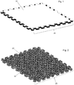
Figure 1 is a perspective top view of a hockey floor tile according to one embodiment of the present invention; -
Figure 2 is a perspective bottom view of a hockey floor tile according to one embodiment of the present invention; -
Figure 3 is a bottom view of a hockey floor tile according to one embodiment of the present invention; -
Figure 4 is a perspective view of two hockey floor tiles interconnected according to one embodiment of the present invention; -
Figure 5 is a magnified perspective view of a corner of a hockey floor tile as shown inFigure 4 according to one embodiment of the present invention; -
Figure 6 is a magnified view of a first and a second hockey floor tiles aligned allowing an interconnection between the tiles according to one embodiment of the present invention; -
Figure 6A is a front view of the final position of nubs from interconnected and adjacent tiles according to one embodiment of the present invention; -
Figure 6B is a side view of two nubs from interconnected and adjacent tiles according to one embodiment of the present invention; -
Figure 6C is a side view of a furrow interacting with a neck from two adjacent and interconnected tiles according to one embodiment of the present invention; and - Figure 7 is perspective view of four hockey floor tiles interconnected into each other according to one embodiment of the present invention.
- The present invention will now be described more fully hereinafter with reference to the accompanying drawings, in which preferred and other embodiments of the invention are shown. No embodiment described below limits any claimed invention and any claimed invention may cover processes or apparatuses that are not described below. The claimed inventions are not limited to apparatuses or processes having all the features of any one apparatus or process described below or to features common to multiple or all of the apparatuses described below. It is possible that an apparatus or process described below is not an embodiment of any claimed invention.
- The terms "coupled", "connected" and "interconnected", along with their derivatives, may be used herein. It should be understood that these terms are not intended as synonyms for each other. Rather, in particular embodiments, "connected" may be used to indicate that two or more elements are in direct physical or electrical contact with each other. "Coupled" may be used to indicated that two or more elements are in either direct or indirect (with other intervening elements between them) physical or electrical contact with each other, or that the two or more elements co-operate or interact with each other (e.g. as in a cause and effect relationship). The term interconnected can also include a modular aspect to the components allowing for easy construction or flexible arrangement.
- With reference to
Figures 1, 2 and3 , and according to one embodiment of the present invention, ahockey floor tile 10 is shown. The hockey floor tile is comprised of anupper surface 15, alower surface 20, and interconnectingmechanisms 25 along the length or edges of thehockey floor tile 10. A worker skilled in the relevant art would appreciate that the interconnectingmechanism 25 can be located on two, three, or four sides of thehockey floor tile 10, depending on the placement of thehockey floor tile 10 within an overall surface comprised of hockey floor tiles of the present invention. Thehockey floor tiles 10 used to form the outer perimeter of a large surface can contain four or three interconnectingmechanism 25 along the edges of such tiles, while for example hockey floor tiles used for corners for a large surface can contain two ormore interconnecting mechanisms 25 along the edges of such corner tiles. Theupper surface 15 of thehockey floor tiles 10 contains a smooth ice like surface, which allows for a smooth surface to be present and provides a sliding feature for pucks. A worker skilled in the relevant art would appreciate the consistency and density of the material of theupper surface 15 that would replicate a smooth surface allowing for an ease to pass packs on the tiles. A worker skilled in the relevant art would also be familiar with the positioning of thelocking mechanism 25 along the length oftile 10. - With specific reference to
Figure 2 , thelower surface 20 oftile 10 is shown in greater detail. Thelower surface 20 contains support points comprising of a series of cup shapedprojections 30. The cup shapedprojections 30 are evenly dispersed throughout thelower surface 20. The cup shapedprojections 30 allowtile 10 to contain depth without using excessive amount of material. In addition, the cup shapedprojections 30 maintain theupper surface 15 level and prevent depressions from being created onupper surface 15 when individuals place their weight onto thetiles 10. A number of different projections can be used as support points in order to provide stability to a hockey tile of the present invention. A worker skilled in the relevant art would be familiar with a number of different projections allowing support of the present hockey tile. - With specific reference to
Figure 3 , a bottom view of ahockey flooring tile 10 is shown. The bottom view further illustrates the numerous interconnectingmechanisms 25 positioned on all sides oftile 10 or along the edges oftile 10. The interconnectingmechanisms 25 are further comprised of a series of repeatingnecks 26 and a series of repeatingfurrows 27 wherein each neck has a similar shape and each furrow has a similar shape which is different than the shape of a neck. This interconnecting mechanism allows for necks and furrows to interconnect with another flooring tile of the present invention. The interconnectingmechanism 25 allow for adjacenthockey floor tiles 10 to interconnect with one another through the mating ofnecks 26 and furrows 27. The specific patterns of the interconnectingmechanisms 25 allows an interconnection between adjacenthockey floor tiles 10 in only one orientation. - With further reference to
Figure 3 and according to one embodiment of the present invention, a guidingneck 28 is positioned within the series of necks and furrows along the edge of a hockey flooring tile. The guidingneck 28 facilitates the interconnection of two flooring tiles given the unique shape of the guidingneck 28 versus the shape ofneck 26. In one embodiment, guidingneck 28 can be positioned on each edge of a flooring tile. In another embodiment, the guiding neck can be limited to only two edges of a flooring tile. - With reference to
Figures 4 and5 , and according to one embodiment of the present invention, twohockey floor tiles hockey floor tiles tiles hockey floor tiles - With specific reference to
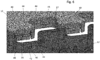
Figure 5 , a magnified view of a corner of thehockey floor tile 12 is shown. The corner edge oftile 12 shows a locking mechanism positioned within the interconnectingmechanism 25. To further lock adjacent tiles together, theneck 26 has amoveable surface 35 having a first andsecond nubs neck 26 of a hockey tile has first andsecond nubs Furrow 27 onhockey tile 10 also has first andsecond nubs second nubs nub 40 being higher thannub 42. First andsecond nubs nub 44 being higher thannub 46. A worker skilled in the relevant art would appreciate the various orientations of the first andsecond nubs -
Moveable surface 35 will interconnect with a furrow having first and second nubs and the moveability ofsurface 35 will allow the nubs of interconnecting neck and furrow and lock the tiles to one another. Thesurface 35 will move inwards through a pivoting ofsurface 35 allowing nubs of a neck to overlap the nubs in the furrow. This interconnection will be further explained below. - With reference to
Figure 6 , and according to one embodiment of the present invention, the interconnection of twoadjacent tiles Tile 12 is shown as transparent to further illustrate the locking mechanism. The first and second nubs, 40 and 42 oftile 10 align and engage withnubs panel 12 and shown in outline asnubs panel 10.Nubs nub 46 to be positioned underneath and next to nub 40 while nub 44 fromtile 12 is positioned on top and next to nub 42 oftile 10 forming a pattern of 4 nubs in a rectangular shape. Themoveable surface 35 allows for the nubs to interact and interconnect adjacent synthetic ice panels. The nubs on the moveable surfaces and the furrows are all aligned with an off set allowing for an alignment of 4 nubs in a rectangular shape between two adjacent panels. - With reference to
Figure 6A and according to one embodiment of the present invention, the placement of the first and second nubs are shown when two tiles are interconnected to one another. The interaction between these nubs consist of the locking mechanism of the present invention.Nubs nubs tiles Figure 6 . The placement ofnubs - With reference to
Figures 6B and 6C and according to one embodiment of the present invention, a side view ofnubs Figure 6C , in order to interconnect two adjacent tiles,moveable surface 35 onfurrow 27 withnub 46 will move inward allowingnub 46 to travel overnub 40 and rest underneath nub 40 oncenub 46 has clearednub 40. The final position ofnubs Figure 6B sincemoveable surface 35 will pivot inward after nub 46 has clearednub 40. A worker skilled in the relevant art would be familiar with the required elasticity ofmoveable surface 35 in order to allownub 46 to travel overnub 40 as shown inFigure 6C . The interaction betweennub - With reference to Figure 7, and according to one embodiment of the present invention, a set of four
hockey floor tiles - The interconnecting mechanism of the present hockey flooring tile can consist of a series of necks and furrows positioned along the edges of a flooring tile. A neck of a tile can be placed within a furrow of another tile allowing two tiles to be interconnected and provide the interconnecting mechanism of the present tile.
- The locking mechanism of the present hockey flooring tile consist of providing nubs being aligned with an off set on the furrows and necks of the hockey floor tile. The locking of two adjacent hockey flooring tiles occurs when the nubs of an interconnected neck and furrow from two tiles position the nubs within a locked position.
- A worker skilled in the relevant art would be familiar with various shapes that could be used in the interconnecting mechanism and is not to be limited to necks and furrows as shown in the description.
Claims (5)
- A hockey flooring tile comprising:- a top surface (15);- one or more interconnecting mechanisms (25) allowing for an interconnection with another tile;- one or more locking mechanism (25) positioned within the interconnecting mechanism allowing for a tile to be locked to another tile (10), the locking mechanism further comprising moveable surfaces (35); and- a bottom surface (20) having support points to support the tiles when a weight is placed on the tile,characterized in that
said moveable surfaces (35) are pivotable to facilitate the interconnection between the adjacent hockey flooring tiles (10), and
said top surface (15) is a top smooth surface for passing pucks;
wherein the locking mechanism (25) is comprised of four or more nubs (40, 42, 44, 46) positioned on a neck (26) and a furrow (27) within the interconnecting mechanism (25). - A hockey flooring tile of claim 1 wherein the interconnecting mechanism is comprised of a series of necks (26) and a series of furrows (27) along the edges of the flooring tile (10).
- A hockey flooring tile according to claim 1 wherein the interconnecting mechanism is comprised of a series of necks (26) and a series of furrows (27) with said necks and furrows further comprising a series of nubs positioned on the necks and furrows to lock the tile (10) to another tile.
- A hockey flooring tile according to claim 1 further comprising one or more guiding necks (28) allowing to guide an interconnection between two tiles (10).
- A hockey flooring tile according to claim 1 wherein said support points allowing to support a weight positioned on the flooring tile comprise cup shaped projections (30).
Applications Claiming Priority (1)
| Application Number | Priority Date | Filing Date | Title |
|---|---|---|---|
| CA2947352A CA2947352A1 (en) | 2016-11-03 | 2016-11-03 | Hockey flooring tile |
Publications (2)
| Publication Number | Publication Date |
|---|---|
| EP3318696A1 EP3318696A1 (en) | 2018-05-09 |
| EP3318696B1 true EP3318696B1 (en) | 2020-01-01 |
Family
ID=60262762
Family Applications (1)
| Application Number | Title | Priority Date | Filing Date |
|---|---|---|---|
| EP17199845.3A Active EP3318696B1 (en) | 2016-11-03 | 2017-11-03 | Hockey flooring tile |
Country Status (3)
| Country | Link |
|---|---|
| US (1) | US10415258B2 (en) |
| EP (1) | EP3318696B1 (en) |
| CA (2) | CA2947352A1 (en) |
Families Citing this family (4)
| Publication number | Priority date | Publication date | Assignee | Title |
|---|---|---|---|---|
| FR3082537B1 (en) * | 2018-06-15 | 2020-05-29 | Ludovic Loffreda | CLADDING SLAB TO FACILITATE REPEATED ASSEMBLIES / DISASSEMBLINGS |
| US11203762B2 (en) | 2019-11-19 | 2021-12-21 | Inscripta, Inc. | Methods for increasing observed editing in bacteria |
| CN216822705U (en) * | 2022-03-01 | 2022-06-28 | 苏州恒瑞达家用地垫有限公司 | Hidden concatenation ground mat |
| LU502747B1 (en) * | 2022-09-05 | 2024-03-05 | Tarkett Gdl Sa | Flooring tile with interlocking connectors |
Citations (1)
| Publication number | Priority date | Publication date | Assignee | Title |
|---|---|---|---|---|
| WO2011001326A2 (en) * | 2009-06-29 | 2011-01-06 | Flooring Industries Limited, Sarl | Panel, more particularly floor panel |
Family Cites Families (26)
| Publication number | Priority date | Publication date | Assignee | Title |
|---|---|---|---|---|
| US4018025A (en) * | 1975-11-28 | 1977-04-19 | Pawling Rubber Corporation | Ventilated interlocking floor tile |
| US5052158A (en) * | 1990-07-13 | 1991-10-01 | Foam Design Consumer Products, Inc. | Modular locking floor covering |
| US5791114A (en) * | 1997-04-02 | 1998-08-11 | Mandel; Nigel | Quick-assembly interlocking tile |
| US5904021A (en) * | 1997-07-29 | 1999-05-18 | Fisher; Kirk R. | Modular flooring recreational use |
| US6061979A (en) * | 1997-09-30 | 2000-05-16 | Johannes; Nicholas J. | Inline skating sports floor |
| WO2002061206A1 (en) * | 2001-01-29 | 2002-08-08 | Spider Court, Inc. | Modular tile and tile flooring system |
| US6588167B2 (en) * | 2001-11-21 | 2003-07-08 | Kuo Chi Chang | Reversible dual-color floor pad module |
| AUPR998002A0 (en) * | 2002-01-17 | 2002-02-07 | Design Develop Commercialise Pty Ltd | Modular plastic flooring |
| US8099915B2 (en) * | 2005-06-02 | 2012-01-24 | Snapsports Company | Modular floor tile with resilient support members |
| US20070059481A1 (en) * | 2005-09-15 | 2007-03-15 | Lin Chien J | Floor pads |
| US7797890B2 (en) * | 2006-02-24 | 2010-09-21 | The Parallax Group International, Llc | Interlocking floor tiles with mushroom shaped connectors |
| US20090047451A1 (en) * | 2007-08-17 | 2009-02-19 | Huss Philip C | Molded mat, and a method and a mold for making the mat |
| US8266849B2 (en) * | 2009-05-27 | 2012-09-18 | Mcfarland Cascade Holdings, Inc. | Interlocking platform panels and modules |
| US8782989B2 (en) * | 2009-06-11 | 2014-07-22 | Comc, Llc | Narrow lined modular flooring assemblies |
| US8307600B2 (en) * | 2009-07-02 | 2012-11-13 | Dollamur Lp | Mat connecting system |
| US8806831B1 (en) * | 2010-03-10 | 2014-08-19 | Steven Ivan Dreyer | Interlocking floor tiles |
| GB2490870B (en) * | 2011-05-09 | 2015-03-25 | John Michael Thorpe | Interlocking synthetic ice skating floor panels |
| FR2989984B1 (en) * | 2012-04-27 | 2014-05-23 | Floor Eco | SLAB FOR FLOOR COVERING, AND FLOORING OF SOIL FORMED SUCH SLABS ASSEMBLED |
| US8806822B1 (en) * | 2013-02-19 | 2014-08-19 | Wen Ping Wang | Mat with puzzle function |
| DE202013101282U1 (en) * | 2013-03-25 | 2013-04-09 | Jürgen Weiss | Floor, wall and ceiling coverings |
| US10369739B2 (en) * | 2013-04-18 | 2019-08-06 | Viconic Sporting Llc | Surface underlayment system with interlocking resilient assemblies of shock tiles |
| CA2953837C (en) * | 2013-07-15 | 2018-08-14 | John Bradley MATCHUNG | Modular flooring system |
| EP2894276A1 (en) * | 2014-01-10 | 2015-07-15 | Sekisui Alveo AG | Interlocking polymer foam floor underlay element |
| US20150361675A1 (en) * | 2014-06-13 | 2015-12-17 | Connor Sport Court International, Llc | Synthetic Modular Flooring Apparatus |
| US20160129299A1 (en) * | 2014-11-11 | 2016-05-12 | Howard Hancock Newman | Hinged interlocking tiles |
| US10137639B2 (en) * | 2016-05-12 | 2018-11-27 | R&L Marketing & Sales, Inc. | Method of fabricating an ultrasonically welded mat unit |
-
2016
- 2016-11-03 CA CA2947352A patent/CA2947352A1/en not_active Abandoned
-
2017
- 2017-11-02 CA CA2984560A patent/CA2984560A1/en not_active Abandoned
- 2017-11-02 US US15/801,666 patent/US10415258B2/en not_active Expired - Fee Related
- 2017-11-03 EP EP17199845.3A patent/EP3318696B1/en active Active
Patent Citations (1)
| Publication number | Priority date | Publication date | Assignee | Title |
|---|---|---|---|---|
| WO2011001326A2 (en) * | 2009-06-29 | 2011-01-06 | Flooring Industries Limited, Sarl | Panel, more particularly floor panel |
Also Published As
| Publication number | Publication date |
|---|---|
| US10415258B2 (en) | 2019-09-17 |
| EP3318696A1 (en) | 2018-05-09 |
| US20180119430A1 (en) | 2018-05-03 |
| CA2947352A1 (en) | 2018-05-03 |
| CA2984560A1 (en) | 2018-05-03 |
Similar Documents
| Publication | Publication Date | Title |
|---|---|---|
| EP3318696B1 (en) | Hockey flooring tile | |
| US7918057B2 (en) | Modular floor tile system with sliding lock | |
| EP1466061A1 (en) | Modular plastic flooring | |
| DK3074104T3 (en) | BUILDING PLATE FOR A TOY BUILDING KIT AND A TOY BUILDING KIT WITH SUCH A BUILDING PLATE | |
| US5950378A (en) | Composite modular floor tile | |
| US2740167A (en) | Interlocking parquet block | |
| US6751912B2 (en) | Modular tile and tile flooring system | |
| US10968573B2 (en) | Fall protecting flooring element primarily for covering playgrounds and flooring composed therefrom | |
| US7490443B1 (en) | Modular flooring system | |
| CA2924162C (en) | Tile for use in a modular flooring system | |
| EP1047847A1 (en) | Support for paving or decking | |
| US8973328B2 (en) | Floor tile expansion joint | |
| EP3216505B1 (en) | Playmat | |
| IL174754A (en) | Constructional panels | |
| SK122895A3 (en) | Raised floor with modular slabs | |
| WO2012158037A1 (en) | Assembly of tiles for forming a floor | |
| US20150233129A1 (en) | Tile Separator | |
| US5428934A (en) | Interlocking slab elements | |
| FI63862B (en) | SAERSKILT FOER TENNISPLANER AVSEDD MARK- ELLER GOLVBELAEGGNING | |
| GB2374879A (en) | Portable outdoor flooring assembly | |
| CA1145784A (en) | Surface covering | |
| ES2323674T3 (en) | SOIL COATING SYSTEM WITH A SOIL STRATEGY AND SUBSUELO PANELS. | |
| KR20220153765A (en) | Board for floor and construction method thereof | |
| AU2041299A (en) | Support for paving or decking | |
| JPS61109586A (en) | Surface coating body for outdoor tennis court |
Legal Events
| Date | Code | Title | Description |
|---|---|---|---|
| PUAI | Public reference made under article 153(3) epc to a published international application that has entered the european phase |
Free format text: ORIGINAL CODE: 0009012 |
|
| STAA | Information on the status of an ep patent application or granted ep patent |
Free format text: STATUS: THE APPLICATION HAS BEEN PUBLISHED |
|
| AK | Designated contracting states |
Kind code of ref document: A1 Designated state(s): AL AT BE BG CH CY CZ DE DK EE ES FI FR GB GR HR HU IE IS IT LI LT LU LV MC MK MT NL NO PL PT RO RS SE SI SK SM TR |
|
| AX | Request for extension of the european patent |
Extension state: BA ME |
|
| STAA | Information on the status of an ep patent application or granted ep patent |
Free format text: STATUS: REQUEST FOR EXAMINATION WAS MADE |
|
| 17P | Request for examination filed |
Effective date: 20181108 |
|
| RBV | Designated contracting states (corrected) |
Designated state(s): AL AT BE BG CH CY CZ DE DK EE ES FI FR GB GR HR HU IE IS IT LI LT LU LV MC MK MT NL NO PL PT RO RS SE SI SK SM TR |
|
| STAA | Information on the status of an ep patent application or granted ep patent |
Free format text: STATUS: EXAMINATION IS IN PROGRESS |
|
| 17Q | First examination report despatched |
Effective date: 20190401 |
|
| GRAP | Despatch of communication of intention to grant a patent |
Free format text: ORIGINAL CODE: EPIDOSNIGR1 |
|
| STAA | Information on the status of an ep patent application or granted ep patent |
Free format text: STATUS: GRANT OF PATENT IS INTENDED |
|
| RIC1 | Information provided on ipc code assigned before grant |
Ipc: A63C 19/10 20060101ALN20190603BHEP Ipc: E01C 13/10 20060101ALI20190603BHEP Ipc: E04F 15/02 20060101AFI20190603BHEP Ipc: E04F 15/22 20060101ALI20190603BHEP Ipc: E04F 15/18 20060101ALI20190603BHEP Ipc: E01C 13/04 20060101ALI20190603BHEP |
|
| INTG | Intention to grant announced |
Effective date: 20190624 |
|
| RIC1 | Information provided on ipc code assigned before grant |
Ipc: E04F 15/22 20060101ALI20190607BHEP Ipc: A63C 19/10 20060101ALN20190607BHEP Ipc: E04F 15/02 20060101AFI20190607BHEP Ipc: E04F 15/18 20060101ALI20190607BHEP Ipc: E01C 13/10 20060101ALI20190607BHEP Ipc: E01C 13/04 20060101ALI20190607BHEP |
|
| GRAS | Grant fee paid |
Free format text: ORIGINAL CODE: EPIDOSNIGR3 |
|
| GRAA | (expected) grant |
Free format text: ORIGINAL CODE: 0009210 |
|
| STAA | Information on the status of an ep patent application or granted ep patent |
Free format text: STATUS: THE PATENT HAS BEEN GRANTED |
|
| AK | Designated contracting states |
Kind code of ref document: B1 Designated state(s): AL AT BE BG CH CY CZ DE DK EE ES FI FR GB GR HR HU IE IS IT LI LT LU LV MC MK MT NL NO PL PT RO RS SE SI SK SM TR |
|
| REG | Reference to a national code |
Ref country code: GB Ref legal event code: FG4D |
|
| REG | Reference to a national code |
Ref country code: CH Ref legal event code: EP Ref country code: AT Ref legal event code: REF Ref document number: 1219939 Country of ref document: AT Kind code of ref document: T Effective date: 20200115 |
|
| REG | Reference to a national code |
Ref country code: DE Ref legal event code: R096 Ref document number: 602017010344 Country of ref document: DE |
|
| REG | Reference to a national code |
Ref country code: IE Ref legal event code: FG4D |
|
| REG | Reference to a national code |
Ref country code: FI Ref legal event code: FGE |
|
| REG | Reference to a national code |
Ref country code: SE Ref legal event code: TRGR |
|
| REG | Reference to a national code |
Ref country code: NL Ref legal event code: MP Effective date: 20200101 |
|
| REG | Reference to a national code |
Ref country code: LT Ref legal event code: MG4D |
|
| PG25 | Lapsed in a contracting state [announced via postgrant information from national office to epo] |
Ref country code: PT Free format text: LAPSE BECAUSE OF FAILURE TO SUBMIT A TRANSLATION OF THE DESCRIPTION OR TO PAY THE FEE WITHIN THE PRESCRIBED TIME-LIMIT Effective date: 20200527 Ref country code: RS Free format text: LAPSE BECAUSE OF FAILURE TO SUBMIT A TRANSLATION OF THE DESCRIPTION OR TO PAY THE FEE WITHIN THE PRESCRIBED TIME-LIMIT Effective date: 20200101 Ref country code: NL Free format text: LAPSE BECAUSE OF FAILURE TO SUBMIT A TRANSLATION OF THE DESCRIPTION OR TO PAY THE FEE WITHIN THE PRESCRIBED TIME-LIMIT Effective date: 20200101 Ref country code: LT Free format text: LAPSE BECAUSE OF FAILURE TO SUBMIT A TRANSLATION OF THE DESCRIPTION OR TO PAY THE FEE WITHIN THE PRESCRIBED TIME-LIMIT Effective date: 20200101 Ref country code: NO Free format text: LAPSE BECAUSE OF FAILURE TO SUBMIT A TRANSLATION OF THE DESCRIPTION OR TO PAY THE FEE WITHIN THE PRESCRIBED TIME-LIMIT Effective date: 20200401 |
|
| REG | Reference to a national code |
Ref country code: SK Ref legal event code: T3 Ref document number: E 34409 Country of ref document: SK |
|
| PG25 | Lapsed in a contracting state [announced via postgrant information from national office to epo] |
Ref country code: BG Free format text: LAPSE BECAUSE OF FAILURE TO SUBMIT A TRANSLATION OF THE DESCRIPTION OR TO PAY THE FEE WITHIN THE PRESCRIBED TIME-LIMIT Effective date: 20200401 Ref country code: LV Free format text: LAPSE BECAUSE OF FAILURE TO SUBMIT A TRANSLATION OF THE DESCRIPTION OR TO PAY THE FEE WITHIN THE PRESCRIBED TIME-LIMIT Effective date: 20200101 Ref country code: HR Free format text: LAPSE BECAUSE OF FAILURE TO SUBMIT A TRANSLATION OF THE DESCRIPTION OR TO PAY THE FEE WITHIN THE PRESCRIBED TIME-LIMIT Effective date: 20200101 Ref country code: GR Free format text: LAPSE BECAUSE OF FAILURE TO SUBMIT A TRANSLATION OF THE DESCRIPTION OR TO PAY THE FEE WITHIN THE PRESCRIBED TIME-LIMIT Effective date: 20200402 Ref country code: IS Free format text: LAPSE BECAUSE OF FAILURE TO SUBMIT A TRANSLATION OF THE DESCRIPTION OR TO PAY THE FEE WITHIN THE PRESCRIBED TIME-LIMIT Effective date: 20200501 |
|
| REG | Reference to a national code |
Ref country code: DE Ref legal event code: R097 Ref document number: 602017010344 Country of ref document: DE |
|
| PG25 | Lapsed in a contracting state [announced via postgrant information from national office to epo] |
Ref country code: ES Free format text: LAPSE BECAUSE OF FAILURE TO SUBMIT A TRANSLATION OF THE DESCRIPTION OR TO PAY THE FEE WITHIN THE PRESCRIBED TIME-LIMIT Effective date: 20200101 Ref country code: EE Free format text: LAPSE BECAUSE OF FAILURE TO SUBMIT A TRANSLATION OF THE DESCRIPTION OR TO PAY THE FEE WITHIN THE PRESCRIBED TIME-LIMIT Effective date: 20200101 Ref country code: DK Free format text: LAPSE BECAUSE OF FAILURE TO SUBMIT A TRANSLATION OF THE DESCRIPTION OR TO PAY THE FEE WITHIN THE PRESCRIBED TIME-LIMIT Effective date: 20200101 Ref country code: SM Free format text: LAPSE BECAUSE OF FAILURE TO SUBMIT A TRANSLATION OF THE DESCRIPTION OR TO PAY THE FEE WITHIN THE PRESCRIBED TIME-LIMIT Effective date: 20200101 Ref country code: RO Free format text: LAPSE BECAUSE OF FAILURE TO SUBMIT A TRANSLATION OF THE DESCRIPTION OR TO PAY THE FEE WITHIN THE PRESCRIBED TIME-LIMIT Effective date: 20200101 |
|
| PLBE | No opposition filed within time limit |
Free format text: ORIGINAL CODE: 0009261 |
|
| STAA | Information on the status of an ep patent application or granted ep patent |
Free format text: STATUS: NO OPPOSITION FILED WITHIN TIME LIMIT |
|
| REG | Reference to a national code |
Ref country code: AT Ref legal event code: MK05 Ref document number: 1219939 Country of ref document: AT Kind code of ref document: T Effective date: 20200101 |
|
| 26N | No opposition filed |
Effective date: 20201002 |
|
| PG25 | Lapsed in a contracting state [announced via postgrant information from national office to epo] |
Ref country code: AT Free format text: LAPSE BECAUSE OF FAILURE TO SUBMIT A TRANSLATION OF THE DESCRIPTION OR TO PAY THE FEE WITHIN THE PRESCRIBED TIME-LIMIT Effective date: 20200101 Ref country code: IT Free format text: LAPSE BECAUSE OF FAILURE TO SUBMIT A TRANSLATION OF THE DESCRIPTION OR TO PAY THE FEE WITHIN THE PRESCRIBED TIME-LIMIT Effective date: 20200101 |
|
| PG25 | Lapsed in a contracting state [announced via postgrant information from national office to epo] |
Ref country code: PL Free format text: LAPSE BECAUSE OF FAILURE TO SUBMIT A TRANSLATION OF THE DESCRIPTION OR TO PAY THE FEE WITHIN THE PRESCRIBED TIME-LIMIT Effective date: 20200101 Ref country code: SI Free format text: LAPSE BECAUSE OF FAILURE TO SUBMIT A TRANSLATION OF THE DESCRIPTION OR TO PAY THE FEE WITHIN THE PRESCRIBED TIME-LIMIT Effective date: 20200101 |
|
| PG25 | Lapsed in a contracting state [announced via postgrant information from national office to epo] |
Ref country code: MC Free format text: LAPSE BECAUSE OF FAILURE TO SUBMIT A TRANSLATION OF THE DESCRIPTION OR TO PAY THE FEE WITHIN THE PRESCRIBED TIME-LIMIT Effective date: 20200101 |
|
| REG | Reference to a national code |
Ref country code: CH Ref legal event code: PL |
|
| PG25 | Lapsed in a contracting state [announced via postgrant information from national office to epo] |
Ref country code: LU Free format text: LAPSE BECAUSE OF NON-PAYMENT OF DUE FEES Effective date: 20201103 |
|
| REG | Reference to a national code |
Ref country code: BE Ref legal event code: MM Effective date: 20201130 |
|
| PG25 | Lapsed in a contracting state [announced via postgrant information from national office to epo] |
Ref country code: CH Free format text: LAPSE BECAUSE OF NON-PAYMENT OF DUE FEES Effective date: 20201130 Ref country code: LI Free format text: LAPSE BECAUSE OF NON-PAYMENT OF DUE FEES Effective date: 20201130 |
|
| PG25 | Lapsed in a contracting state [announced via postgrant information from national office to epo] |
Ref country code: IE Free format text: LAPSE BECAUSE OF NON-PAYMENT OF DUE FEES Effective date: 20201103 |
|
| PGFP | Annual fee paid to national office [announced via postgrant information from national office to epo] |
Ref country code: SE Payment date: 20211130 Year of fee payment: 5 Ref country code: SK Payment date: 20211102 Year of fee payment: 5 Ref country code: DE Payment date: 20211130 Year of fee payment: 5 Ref country code: FR Payment date: 20211129 Year of fee payment: 5 Ref country code: FI Payment date: 20211126 Year of fee payment: 5 Ref country code: CZ Payment date: 20211102 Year of fee payment: 5 Ref country code: GB Payment date: 20211124 Year of fee payment: 5 |
|
| PG25 | Lapsed in a contracting state [announced via postgrant information from national office to epo] |
Ref country code: TR Free format text: LAPSE BECAUSE OF FAILURE TO SUBMIT A TRANSLATION OF THE DESCRIPTION OR TO PAY THE FEE WITHIN THE PRESCRIBED TIME-LIMIT Effective date: 20200101 Ref country code: MT Free format text: LAPSE BECAUSE OF FAILURE TO SUBMIT A TRANSLATION OF THE DESCRIPTION OR TO PAY THE FEE WITHIN THE PRESCRIBED TIME-LIMIT Effective date: 20200101 Ref country code: CY Free format text: LAPSE BECAUSE OF FAILURE TO SUBMIT A TRANSLATION OF THE DESCRIPTION OR TO PAY THE FEE WITHIN THE PRESCRIBED TIME-LIMIT Effective date: 20200101 |
|
| PG25 | Lapsed in a contracting state [announced via postgrant information from national office to epo] |
Ref country code: MK Free format text: LAPSE BECAUSE OF FAILURE TO SUBMIT A TRANSLATION OF THE DESCRIPTION OR TO PAY THE FEE WITHIN THE PRESCRIBED TIME-LIMIT Effective date: 20200101 Ref country code: AL Free format text: LAPSE BECAUSE OF FAILURE TO SUBMIT A TRANSLATION OF THE DESCRIPTION OR TO PAY THE FEE WITHIN THE PRESCRIBED TIME-LIMIT Effective date: 20200101 |
|
| PG25 | Lapsed in a contracting state [announced via postgrant information from national office to epo] |
Ref country code: BE Free format text: LAPSE BECAUSE OF NON-PAYMENT OF DUE FEES Effective date: 20201130 |
|
| REG | Reference to a national code |
Ref country code: DE Ref legal event code: R119 Ref document number: 602017010344 Country of ref document: DE |
|
| REG | Reference to a national code |
Ref country code: SK Ref legal event code: MM4A Ref document number: E 34409 Country of ref document: SK Effective date: 20221103 |
|
| REG | Reference to a national code |
Ref country code: SE Ref legal event code: EUG |
|
| GBPC | Gb: european patent ceased through non-payment of renewal fee |
Effective date: 20221103 |
|
| PG25 | Lapsed in a contracting state [announced via postgrant information from national office to epo] |
Ref country code: CZ Free format text: LAPSE BECAUSE OF NON-PAYMENT OF DUE FEES Effective date: 20221103 |
|
| PG25 | Lapsed in a contracting state [announced via postgrant information from national office to epo] |
Ref country code: SK Free format text: LAPSE BECAUSE OF NON-PAYMENT OF DUE FEES Effective date: 20221103 Ref country code: SE Free format text: LAPSE BECAUSE OF NON-PAYMENT OF DUE FEES Effective date: 20221104 |
|
| PG25 | Lapsed in a contracting state [announced via postgrant information from national office to epo] |
Ref country code: GB Free format text: LAPSE BECAUSE OF NON-PAYMENT OF DUE FEES Effective date: 20221103 Ref country code: DE Free format text: LAPSE BECAUSE OF NON-PAYMENT OF DUE FEES Effective date: 20230601 |
|
| PG25 | Lapsed in a contracting state [announced via postgrant information from national office to epo] |
Ref country code: FR Free format text: LAPSE BECAUSE OF NON-PAYMENT OF DUE FEES Effective date: 20221130 |