US8307600B2 - Mat connecting system - Google Patents
Mat connecting system Download PDFInfo
- Publication number
- US8307600B2 US8307600B2 US12/458,193 US45819309A US8307600B2 US 8307600 B2 US8307600 B2 US 8307600B2 US 45819309 A US45819309 A US 45819309A US 8307600 B2 US8307600 B2 US 8307600B2
- Authority
- US
- United States
- Prior art keywords
- mats
- mat
- connector
- trench
- foam
- Prior art date
- Legal status (The legal status is an assumption and is not a legal conclusion. Google has not performed a legal analysis and makes no representation as to the accuracy of the status listed.)
- Expired - Fee Related, expires
Links
Images


Classifications
-
- A—HUMAN NECESSITIES
- A63—SPORTS; GAMES; AMUSEMENTS
- A63B—APPARATUS FOR PHYSICAL TRAINING, GYMNASTICS, SWIMMING, CLIMBING, OR FENCING; BALL GAMES; TRAINING EQUIPMENT
- A63B6/00—Mats or the like for absorbing shocks for jumping, gymnastics or the like
-
- E—FIXED CONSTRUCTIONS
- E04—BUILDING
- E04F—FINISHING WORK ON BUILDINGS, e.g. STAIRS, FLOORS
- E04F15/00—Flooring
- E04F15/02—Flooring or floor layers composed of a number of similar elements
-
- E—FIXED CONSTRUCTIONS
- E04—BUILDING
- E04F—FINISHING WORK ON BUILDINGS, e.g. STAIRS, FLOORS
- E04F2201/00—Joining sheets or plates or panels
- E04F2201/06—Magnets
-
- E—FIXED CONSTRUCTIONS
- E04—BUILDING
- E04F—FINISHING WORK ON BUILDINGS, e.g. STAIRS, FLOORS
- E04F2201/00—Joining sheets or plates or panels
- E04F2201/07—Joining sheets or plates or panels with connections using a special adhesive material
-
- E—FIXED CONSTRUCTIONS
- E04—BUILDING
- E04F—FINISHING WORK ON BUILDINGS, e.g. STAIRS, FLOORS
- E04F2201/00—Joining sheets or plates or panels
- E04F2201/08—Joining sheets or plates or panels hook and loop-type fastener or similar fixing means
-
- Y—GENERAL TAGGING OF NEW TECHNOLOGICAL DEVELOPMENTS; GENERAL TAGGING OF CROSS-SECTIONAL TECHNOLOGIES SPANNING OVER SEVERAL SECTIONS OF THE IPC; TECHNICAL SUBJECTS COVERED BY FORMER USPC CROSS-REFERENCE ART COLLECTIONS [XRACs] AND DIGESTS
- Y10—TECHNICAL SUBJECTS COVERED BY FORMER USPC
- Y10T—TECHNICAL SUBJECTS COVERED BY FORMER US CLASSIFICATION
- Y10T24/00—Buckles, buttons, clasps, etc.
- Y10T24/31—Plural fasteners having intermediate flaccid connector
- Y10T24/314—Elastic connector
- Y10T24/316—Strap connector
-
- Y—GENERAL TAGGING OF NEW TECHNOLOGICAL DEVELOPMENTS; GENERAL TAGGING OF CROSS-SECTIONAL TECHNOLOGIES SPANNING OVER SEVERAL SECTIONS OF THE IPC; TECHNICAL SUBJECTS COVERED BY FORMER USPC CROSS-REFERENCE ART COLLECTIONS [XRACs] AND DIGESTS
- Y10—TECHNICAL SUBJECTS COVERED BY FORMER USPC
- Y10T—TECHNICAL SUBJECTS COVERED BY FORMER US CLASSIFICATION
- Y10T24/00—Buckles, buttons, clasps, etc.
- Y10T24/32—Buckles, buttons, clasps, etc. having magnetic fastener
-
- Y—GENERAL TAGGING OF NEW TECHNOLOGICAL DEVELOPMENTS; GENERAL TAGGING OF CROSS-SECTIONAL TECHNOLOGIES SPANNING OVER SEVERAL SECTIONS OF THE IPC; TECHNICAL SUBJECTS COVERED BY FORMER USPC CROSS-REFERENCE ART COLLECTIONS [XRACs] AND DIGESTS
- Y10—TECHNICAL SUBJECTS COVERED BY FORMER USPC
- Y10T—TECHNICAL SUBJECTS COVERED BY FORMER US CLASSIFICATION
- Y10T428/00—Stock material or miscellaneous articles
- Y10T428/24—Structurally defined web or sheet [e.g., overall dimension, etc.]
- Y10T428/24008—Structurally defined web or sheet [e.g., overall dimension, etc.] including fastener for attaching to external surface
Definitions
- the present invention relates generally to mats used in athletic activities. More particularly, the present invention relates to a system for connecting mats together.
- mats are used to provide a soft surface for the athletes. Many of these athletic activities occur in gymnasiums or other locations which are used for a variety of different purposes. Therefore, it is not always desired that the mats be positioned on the floor permanently or for long periods. Rather, mats are often spread out on a floor and removed depending on the activity to be conducted.
- mats are arranged adjacent to each other in order to provide a large padded surface.
- they can move or shift in position causing gaps between the mats. This is generally an undesirable condition for a variety of reasons. For example, if the mats move or shift with respect to each other, gaps may occur exposing unpadded portions of the floor. Also, the top surface of the mats may be noncontiguous which may also be undesirable.
- mats may be arranged on a floor for a specific activity and then be removed and stored when a different activity is to take place on the same floor, it is desirable to provide a system that allows the mats to be easily attached and separated.
- the system is reusable in that it may permit the mats to be connected and then separated multiple times.
- the system may allow the mats to be attached to each other and form a substantially contiguous top surface.
- the mats may be secured by a connecting system to reduce the likelihood of the mats moving with respect to each other to provide gaps between the mats.
- a system that, in some embodiments, provides a system for connecting mats together.
- the system may include a first and second mat having foam portions; a trench located in the foam portion of one of the mats, the trench spaced from an edge of the mat, the trench running substantially parallel to the edge of the mat; and a connector configured to be inserted into the trench to connect the first and second mats together, wherein when the mats are connected together, the mats define a substantially contiguous surface.
- a system for attaching mats together may include a mat having a top surface; a relief section in the mat interrupting the top surface, the relief section proximate to an edge of the mat; a first attaching material attached to the mat and located in the relief section; and a connector having a back surface, the connector including second attaching material attached to a surface opposite the back surface, the connector dimensioned and configured to fit in the relief section when the first and second attaching material are attached to each other, wherein the top surface of the mat and the back surface of the connector form a substantially contiguous surface when the first and second attaching material are connected to each other.
- a system for attaching mats together may include a mat having a foam interior; a magnet located in a recess in the foam near an edge of the mat; and a seam in the foam running though the recess.
- a system for retaining mats may include a first retainer; a second retainer; and a tension strip configured to removably connect to the first and second retainers to retain mats between the first and second retainers, wherein each retainer comprises: an anti-lifting plate; a retaining plate mounted to the anti-lifting plate wherein the anti-lifting plate extends past the retaining plate; and a connector attached to the anti-lifting plate on a side of the anti-lifting plate opposite to the retaining plate, the connectors configured to attach to the tension strip via a hook and loop connection.
- FIG. 1 is a side view of two mats connected together by a mat connecting system in accordance with one embodiment in accordance with the present invention.
- FIG. 2 is a side view of two mats connected together with a mat connecting system in accordance with another embodiment.
- FIG. 3 is an exploded side view illustrating a connecting system in accordance with the embodiment shown in FIG. 2 .
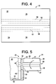
- FIG. 4 is a top view of two mats connected together by a mat connecting system in accordance with the embodiment shown in FIGS. 2 and 3 .
- FIG. 5 is a perspective view of two mats being connected to each other according to the mat connecting system shown in the embodiment of FIGS. 2-4 .
- FIG. 6 is a side view of two mats having a connecting system in accordance with another embodiment.
- FIG. 7 is a side view of two mats connected to each other using a connecting system in accordance with the embodiment shown in FIG. 6 .
- FIG. 8 is a top view of two mats connected to each other using a connecting system according to the embodiment shown in FIGS. 6 and 7 .
- FIG. 9 is a perspective view of a mat being assembled having a connecting system according to another embodiment.
- FIG. 10 is a perspective view of a mat being assembled having a connecting system according to another embodiment.
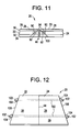
- FIG. 11 is a side view of two mats connected together with a connecting system including magnets.
- FIG. 12 is a perspective view of two mats connected together by a connecting system according to another embodiment.
- FIG. 13 is a side view of two mats held in place by a connecting system shown in FIG. 12 .
- FIG. 14 is a bottom view of a portion of the connecting system shown in FIGS. 12 and 13 .
- FIG. 15 is a top view of a portion of the connecting system shown in FIG. 14 .
- An embodiment in accordance with the present invention provides a system for retaining or connecting mats together. Mats are often arranged on the floor to provide a padded surface for conducting athletic activities.
- Embodiments in accordance with the present invention may provide a system for retaining the mats together or connecting the mats together so that multiple mats arranged adjacent to each other can provide a large padded surface.
- a variety of different mats may be used in accordance with the invention.
- a mat retaining system 20 is used to connect two mats together.
- a mat 22 is located on the left and a mat 24 is located to the right.
- the mats 22 , 24 each include a foam portion 26 .
- the foam portion 26 may be a polyethylene foam, but other types of foam or padding may also be used.
- the foam portion 26 may be topped with a flexible sheet 28 .
- the flexible sheet 28 protects the foam portion 26 and provides a top or working surface 29 upon which the athletic activities are accomplished.
- the flexible sheet 28 may be vinyl, carpet, such as a needle punch carpet, or any other suitable surface.
- the flexible sheet 28 may be very thin when compared to the foam portion 26 .
- the foam portion 26 shown in FIG. 1 includes a top foam layer 30 located just beneath the flexible sheet 28 .
- a middle foam layer 32 and a bottom foam layer 34 Other mats in accordance with the invention may include more or fewer layers.
- the middle foam layer 32 is made of a comparatively heavier and stiffer foam than the top foam layer 30 and the bottom foam layer 34 .
- the middle foam layer 32 may weigh four pounds per cubic foot, whereas the top foam layer 30 and bottom foam layer 34 may weigh 2.2 pounds per cubic foot. Other weights of foam may also be used.
- the foam layers 30 , 32 , 34 may be laminated together by a flame laminating process.
- a top or bottom surface of one foam layer may be heated by being exposed to a flame to partially melt the foam layer.
- the foam layer is attached to a second foam layer.
- the two foam layers then may be run between two rollers to compress and attach the two foam layers together.
- the foam layers may each be about 5 ⁇ 8 of an inch in thickness, but other thicknesses may be used.
- the flame lamination method may include heating one of the foam layers so that about 1 ⁇ 8 of an inch of the layer is heated to a molten state, then the two foam layers are attached. The above process is described by example only, and other ways of attaching the foam layers may also be used.
- the foam portion 26 may also be flame laminated to the flexible sheet 28 in a process similar to that described above.
- Other mats may be made by sewing, gluing or otherwise attaching the flexible sheet 28 to a foam layer. Some mats may only use one layer of foam, two layers or more layers than the three described with respect to FIG. 1 .
- mats may be segmented in order to allow the mats to be folded for storage.
- Other mats (as shown in FIG. 5 and described in more detail with respect to FIG. 5 ) may be segmented into smaller segments so that the mats may be rolled up for storage.
- the mats 22 and 24 may have slits 60 located in the bottom of the foam portion 26 in order to allow the mats to roll up.
- both the left mat 22 and the right mat 24 include a relief section 36 .
- the relief section 36 may be formed by removing a section of the flexible sheet 28 and a portion of the top foam layer 30 from each mat 22 and 24 .
- the relief section 36 may have a depth of about 3/16 of an inch or less.
- An attaching material 42 is positioned in the relief section 36 . The mats 22 and 24 are arranged so the removed sections are aligned with each other to form a large relief section 36 as shown in FIG. 1 .
- a connector 38 is placed in the relief section 36 and connects the mats 22 and 24 together.
- the connector 38 includes an attaching material 40 .
- the bottom of the relief section 36 of the mats 22 and 24 have a corresponding attaching material 42 .
- the attaching material 42 in the relief section 36 of the mats 22 and 24 attach to the attaching material 40 on the connector 38 .
- the attaching material 40 and 42 is a hook and loop attaching material.
- An example of a hook and loop material is a series of products sold under the name VELCRO.
- the hook portion of the attaching material 40 is located on the connector 38 and the loop portion of the attaching material 42 is mounted to the mats 22 and 24 .
- the loop attaching material 42 may be attached to the foam portion 26 of the mats 22 and 24 by any suitable method such as, but not limited to, flame lamination, gluing using double sided tape, and sewing. Loop material provided with an adhesive on the back may also be used.
- the loop material 42 is attached to the mats 22 and 24 and the hook attaching material 40 is attached to the connector 38 .
- the hook attaching material 40 is attached to the connector 38 because when a hook and loop attaching system starts to fail, often it is the hook portion 40 that fails first.
- a new connector 38 having a new hook attaching material 40 may be used to replace an old worn-out hook attaching material 40 .
- Replacing the connector 38 is easier than replacing worn hook attaching material 40 from the mats 22 and 24 .
- the invention is not limited to such an arrangement.
- Other embodiments may include the hook attaching material 40 connected to the mats 22 and 24 and the loop attaching material 42 connected to the connector 38 .
- the attaching material 40 may be connected to the connector 38 by glue, double sided tape, an adhesive backed to the attaching material 46 , sewing, or any other suitable method.
- the connector 38 , the attaching materials 40 and 42 , and the relief section 36 are dimensioned so that when the connector 38 is attached via the attaching material 40 and 42 to the mats 22 and 24 and a top surface 39 of the connector 38 forms a substantially contiguous surface with the working surface 29 of the mats 22 and 24 .
- a seam 44 between the mats 22 and 24 is formed by the right edge 46 of the left mat 22 and the left edge 48 of the right mat 24 .
- the two mats 22 and 24 are brought close together to minimize the distance between the edge 46 and edge 48 , thus minimizing the size of the seam 44 before the connector 38 is connected to the attaching material 42 .
- the adhesiveness between the attaching material 40 and 42 should be selected to have a relatively high sheer strength in order to resist the mats 22 and 24 from being moved with respect to each other.
- the materials used in the attaching material 40 and 42 can also be selected to have a relatively low strength when being pulled apart from each other.
- FIGS. 2-5 show another embodiment of a mat retaining system 20 in accordance with the invention.
- the left mat 22 is positioned adjacent to the right mat 24 .
- the seam 44 occurs between the mats 22 and 24 between the edge 46 and the edge 48 .
- the top of the mats 28 forms a substantially contiguous top surface 29 .
- a relief portion 50 has been removed from the foam portion 26 of each mat 22 and 24 .
- each mat 22 and 24 has a trench 52 .
- the trench 52 is proximate or near the edge 46 or 48 of the mats 22 and 24 .
- the centers of the trenches 52 may be located about one inch from the edges 46 or 48 .
- the centers of the trenches 52 may be about two inches from each other.
- the trenches 52 may be about 1 inch in width. While not shown, the mats shown in FIGS. 2-5 may be made of multiple layers as described with respect to FIG. 1 .
- Projections 54 are attached to connector 56 .
- the connector 56 may be substantially rigid.
- the connector 56 may be segmented to permit the connector 56 to be rolled up for storage.
- the projections 54 in some of the embodiments may be made of the same foam material as the foam portion 26 .
- the actual foam removed to make the trenches 52 is attached to the connector 56 to form the projections 54 .
- the projections 54 may be made out of different foam or a more rigid substance such as plastic. Any suitable substance may be used in accordance with the invention.
- the connector 56 and the relief portion 50 are dimensioned so that the bottom of the connector 56 and fits flush with the bottom 57 of the mats 22 and 24 when the connector 56 is in the relief portion 50 as shown in FIG. 2 .
- the interaction between the projections 54 and the trenches 52 lock the two mats 22 and 24 together to minimize the width of the seam 44 .
- the arrows A indicate how the connector 56 having the projections 54 fits into the relief portion 50 and the trenches 52 .
- the connector 56 may include a strip of polycarbonate material upon which two foam projections 54 are attached.
- the polycarbonate strip may have a thickness of 3/32 of an inch or less.
- the projections 54 may be attached to the polycarbonate strip by double sided tape, glue, flame lamination, or any other suitable method.
- the polycarbonate strip may be made of a product sold under the trade name LEXAN.
- the trenches 52 may have a depth of about half the thickness of the foam portion 26 of the mats 22 and 24 . Other embodiments may include trenches 52 having other thicknesses.
- the connector 56 is described as including polycarbonate strip, a variety of other materials could be used in accordance with the invention. While the trench 52 and the projections 54 are shown as rectangular in the figures, the trench 52 and projections 54 may be chamfered, rounded, or have some other geometry that may assist the projections 54 in entering the trenches 52 .
- FIG. 4 illustrates the mats 22 and 24 laying adjacent to each other connected by connections system 20 shown in FIGS. 2 , 3 , and 5 .
- the relief portion 50 and trench 52 in the foam portions 26 are shown in phantom lines as they are hidden in the view shown in FIG. 4 .
- FIG. 5 the mat retaining system 20 of FIGS. 2-5 is shown in a perspective view.
- the connector 56 is arranged having the projections 54 extending upward.
- the left hand mat 22 has been arranged to have the projection 54 located in the trench 52 .
- the right hand mat 24 is in a partially rolled up state.
- Slits 60 in the bottom of the foam portion 26 divide the mat 24 into several segments 58 .
- the slits 60 do not extend through the flexible sheet 28 (the flexible sheet 28 is not shown in FIG. 5 , but is shown, for example, in FIG. 2 ). In some embodiments the slits 60 do not extend all the way through the foam portion 26 .
- the slits 60 aid in allowing the mat 24 to roll up when not in use.
- the right hand mat 24 has been positioned adjacent to the left hand mat 22 .
- the right hand mat 24 has been partially unrolled so that some of the segments 58 (hidden in FIG. 5 ) have the trenches 52 aligned with and containing the projection 54 .
- the right hand mat 24 unrolls in the direction as shown by the arrow in FIG. 5 .
- the various segments 58 lay down flat and the trench 52 contains the projection 54 and achieves the position shown in FIGS. 2 and 4 when the mat 24 is fully unrolled.
- the mats 22 and 24 can be rolled up by rolling the mats 22 and 24 in the direction opposite the arrow shown in FIG. 5 .
- the segments 58 may be about 4 inches in width. While the seam 44 is shown as a straight seam in FIGS. 2-5 , a step seam 44 as shown in FIG. 7 may also be used in accordance with the connecting system 20 shown in FIGS. 2-5 .
- FIGS. 6-8 illustrate a mat connecting system 20 in accordance with another embodiment of the invention.
- the left mat 22 includes a foam portion 26 having a top surface 28 made of a flexible sheet to define a substantially flat top surface or working surface 29 .
- the mats 22 and 24 may be layered and made similarly to the mats described above in the embodiments of FIGS. 1-5 .
- the left 22 and right 24 mats have a stepped portion 62 .
- the stepped portion 62 includes a vertical surface 64 which may extend along about half the thickness of the mat 24 , a horizontal surface 66 , and a second vertical surface 70 in the right mat 24 . In the horizontal surface 66 resides a trench 68 .
- the trench 68 runs along the length of the mat 24 proximate to the lower vertical surface 70 .
- the left hand mat 22 includes a vertical surface 72 which extends along about half the thickness of the mat 22 , a horizontal surface 74 , and a second vertical surface 76 .
- a projection 78 projects out of the horizontal surface 74 .
- the projection 78 may be made of foam similar to the foam portion 26 . In other embodiments, the projection 78 may be made of plastic or any other suitable substance.
- the projection 78 may be integral with the foam portion 26 or the projection 78 may be attached to the foam portion 26 in any suitable manner.
- the projection 78 is dimensioned to fit within the trench 68 as shown in FIG. 7 . Putting the projection 78 into the trench 68 secures the left 22 and the right 24 mats to each other and allows the flexible sheets 28 of both the left and right mats 22 and 24 to form a substantially contiguous top or working surface 29 .
- the seam 44 is step shaped as shown in FIG. 7 .
- the trench 68 may be extruded.
- the projection 78 may be die cut.
- the left 22 and right 24 mats themselves may start out having a more rectangular cross section.
- a portion of the flexible sheet 28 may be removed from the left hand side of the right mat 24 to form the step portion 26 and the trench 68 is extruded.
- the left hand mat 22 may also start as having a more rectangular cross section.
- a portion of the foam portion 26 at the bottom part 57 of the mat 24 is removed.
- the projection 78 may be die cut and left attached to the form portion 26 in embodiments where the projection 78 is integral with the foam portion 26 .
- the exposed foam may be coated for protection. Stress points in the system 20 may be reinforced.
- FIG. 8 is a top view of mats 22 and 24 having a retaining system 20 similar to the embodiments shown in FIGS. 6 and 7 .
- FIG. 8 illustrates the left 22 and right mats 24 divided up into segments 58 similar to that descried with respect to FIG. 5 .
- the various segments 58 may be any suitable width, however in accordance with some embodiments of the invention, the segments 58 are about 4 inches wide.
- each segment 58 of mat 22 has its own projection 78 .
- the right hand mat 24 has a single trench 68 . In some embodiments, multiple trenches may be used; one for each section 58 .
- the projection 78 has been shown in the figures to project downward and the trench 68 has been shown to extend downward towards the floor, one skilled in the art would appreciate that the features of the retaining system 20 can be rearranged.
- the projection 78 and trench 68 can be reversed so that the projections are on surface 66 of mat 24 could protrude up and fit into a trench 68 located upward and extending toward the flexible sheet 28 of mat 22 .
- FIGS. 9-11 show embodiments in accordance with the invention where the mat retaining system 20 includes a magnet.
- FIG. 9 shows a mat 22 in a partial state of assembly and in an inverted position so that the top flexible sheet 28 is located on the bottom. While mat 22 is shown in FIGS. 9 and 10 the same depiction and description can apply to the right mat 24 because in the embodiment shown in FIGS. 9-11 the mats 22 and 24 are similar.
- the mat 22 includes a V-shaped trench 82 made when a portion of the foam portion 26 was removed. The walls 96 and 98 of the V-shaped trench may be cut at about a 45° angle with respect to the top surface 29 of the mats 22 and 24 .
- the foam portion 26 may include several foam layers 86 .
- the foam portions 26 and the flexible sheets 28 of the mats 22 and 24 may be constructed as described above. Two foam layers 86 are shown. Some embodiments in accordance with the invention may include more or fewer layers 86 . For example, three layers 30 , 32 , and 36 are shown in FIG. 11 .
- the bottom 88 of the V-shaped trench 82 is located at the flexible sheet 28 .
- the flexible sheet 28 acts as a hinge to allow the mat 22 to be folded along the bottom 88 of the V-shaped trench 82 in the direction of arrow B.
- FIG. 10 shows the mat in a partially folded position.
- FIG. 11 shows a side view of left hand mat 22 and a right hand mat 24 in a fully assembled and attached position.
- the V-shaped trench 82 includes an elongated hole 90 in the right hand side wall 96 of the V-shaped trench 82 and a hole 92 in the left hand side wall 98 of the V-shaped trench 82 .
- the holes 90 and 92 may also be referred to as slots or recesses. These terms are intended to refer to a place for the magnet 94 to reside and be contained rather than a specific shape of the recess. Any suitably shaped recess may be used in accordance with the invention.
- the hole 92 in the left hand side wall 98 of the V-shaped trench 82 contains a magnet 94 .
- the magnet 94 may be a rare earth magnet or any other magnet suitable for the purposes described herein. While the magnet 94 is shown in the hole 92 in the left side wall 98 of the V-shaped trench 82 , the magnet 94 could also be located in the elongated hole 90 in the right hand side wall 96 of the V-shaped trench 82 .
- the mat 22 is folded along the bottom 88 of the V-shaped trench 82 in the direction shown by arrow B until the side walls 96 and 98 are in contact with each other.
- the side walls 96 and 98 may be bonded to each other in a variety of ways. For example, glue, flame lamination, sewing or any other suitable technique for bonding the side walls 96 and 98 together may be used to bond the side walls 96 and 98 together.
- glue, flame lamination, sewing or any other suitable technique for bonding the side walls 96 and 98 together may be used to bond the side walls 96 and 98 together.
- the magnet 94 is trapped within the elongated holes 90 and 92 as shown in FIG. 11 .
- FIG. 10 illustrates an embodiment similar to that shown in FIG. 9 where the mat 22 is comprised of several different segments 58 .
- each segment 58 has elongated holes 90 located in the side wall 96 and elongated holes 92 located in the side wall 98 .
- Magnets 94 are located in the holes 92 as shown in FIG. 10 but in other embodiments, the magnets 94 could be located in the holes 90 .
- the mat 22 is then folded in the direction of arrow B along the bottom 88 of the V-shaped trench 82 until the side walls 96 and 98 contact each other as shown in FIG. 11 .
- Having multiple magnets 94 located in a plurality of holes 90 and 92 in the various segments 58 offers the following advantage. As one mat 22 or 24 is rolled up, only one magnet 94 at a time is separated from a corresponding magnet in a corresponding segment 58 . This makes it easier to separate the mats 22 and 24 when one of the mats 22 or 24 is being rolled up rather than separating all the magnets 94 at once by pulling two mats 22 and 24 apart from each other.
- FIG. 11 shows a mat retaining system 20 using magnets.
- the left mat 22 is butted against the right mat 24 .
- the magnet 94 is retained within the holes 90 and 92 .
- the mats 22 and 24 are retained in place by the attraction of the magnet 94 in mat 22 to the magnet 94 in mat 24 .
- the seam 100 created by attaching walls 96 and 98 (shown in FIGS. 9 and 10 ) to each other, runs through the large hole comprised of the two holes 90 and 92 .
- the flexible sheet 28 extends along the top portion of the mats 22 and 24 and turns at substantially a right angle and extends along the adjacent edges of the mats 22 and 24 as shown.
- the seam 44 formed by the two mats 22 and 24 is comprised of the two flexible sheets 28 from the mats 22 and 24 butting against each other.
- the mats 22 and 24 are held in place by the attraction between the magnets 94 contained in each of the mats 22 and 24 .
- the flexible sheet 28 of the mats 22 and 24 comprise a substantially flat top surface or working surface 29 .
- the mats 22 and 24 comprise three foam layers 30 , 34 , 36 described above. While the holes 90 and 92 are shown to be fully within the middle layer 34 other embodiments of the invention may locate the holes 90 and 92 within more than one layer. Further, some embodiments of the invention may include more or fewer layers of foam than that shown in FIG. 11 . In some embodiments, the holes 90 and 92 may be lined with a reinforcing material.
- FIGS. 12-15 illustrate a mat retaining system 20 in accordance with another embodiment.
- a left hand 22 and right hand mat 24 are arranged adjacent to each other.
- the mats 22 and 24 butt up against each other forming a seam 44 .
- the top sheets 28 of the two mats 22 and 24 form a substantially contiguous top or working surface 29 .
- the mat retaining system 20 keeps the mats 22 and 24 from spreading apart from each other.
- the mat retaining system 20 includes a tension strip 102 .
- the tension strip 102 lays beneath the mats 22 and 24 .
- Retainers 104 are located on, and attached to, the tension strip 102 .
- the retainers 104 butt against the outer edges 106 and 108 of the mats 22 and 24 to keep the mats 22 and 24 from spreading apart from each other. Multiple sets of tension strips 102 and retainers 104 may be used.
- FIG. 13 shows a side view of the retaining system 20 and mats 22 and 24 .
- the tension strip 102 runs beneath the mats 22 and 24 and the retainers 104 .
- the tension strip 102 may extend about two feet past each mat 22 and 24 .
- the retainers 104 include a foam portion 112 and a top portion 114 .
- the top portion 114 may be a carpeted surface or a flexible sheet similar to the flexible sheet 28 topping the mats 22 and 24 .
- the top portion 114 forms a substantially continuous surface with the top portion 29 of the mats 22 and 24 .
- the top portion 114 is attached to the foam portion 112 in any suitable manner.
- FIG. 14 shows a bottom view of the retainer 104 .
- the retainer 104 includes an anti-lift plate 116 .
- the foam portion 112 is attached to the anti-lift plate 116 in any suitable manner.
- the anti-lift plate 116 is substantially rigid and may be made of metal, plastic, or any other suitable substance.
- a connector 118 is attached to the bottom 126 of the anti-lift plate 116 .
- the connector 118 may be one portion of a hook and loop attaching connector system, and in some embodiments of the invention, may be the loop portion of a hook and loop fastening system. As shown in FIG.
- a connector 118 may include two strips of loop material attached to the bottom 126 of the anti-lift plate 116 .
- the connector 114 has an edge 124 which butts against an edge 106 or 108 of the mat 22 or 24 shown in FIG. 13 to keep the mats 22 and 24 from moving away from each other.
- a top portion 114 is a carpeted portion, a vinyl sheet, or other flexible surface that forms a contiguous surface with the top portion 29 of the mats 22 and 24 .
- the tension strip 102 may be a strip of hook fastening material 120 to which the loop connector 118 located on the retainer 104 is connected.
- the mats 22 and 24 are placed on the tension strip 102 .
- the mats 22 or 24 are pushed up against the edge 124 of the retainer 104 .
- the mats 22 and 24 are also pushed against each other to minimize the seam 44 .
- the tension strip 102 is then pulled tight and a second retainer 104 is put down and attached by hook and loop connection to the tension strip 102 .
- the mats 22 and 24 are trapped between retainers 104 . While FIG.
- FIG. 12 shows 2 sets of retainers 104 and tension strips 102 , as many sets may be used as needed to secure groups of mats (the system 20 may connect more than just two mats) together.
- one tension strip 102 and set of retainers 104 may be located every six feet along the mats.
- the anti-lift plate 116 is configured to prevent or reduce the likelihood of the retainer 104 from moving out of position due to the tension within the tension strip 102 .
- the various features of the mat retaining system 20 have been described herein according to one of the several embodiments set forth above.
- the various mat retaining systems 20 may mix and combine various features of the several embodiments in order to attach mats 22 and 24 to each other.
- the tension strip 102 and retainer 104 may be used in conjunction with the other mat retaining systems described herein.
- Hook and loop fastening systems may also be combined with the projection and trench and/or magnet system.
- the magnets and projection and trench systems may also be used together. While many of the seams have been shown as straight seams, step-type seams as shown and described herein may be substituted for straight seams as desired.
- one skilled in the art may mix and match features of the various embodiments in accordance with the invention to provide a system tailored for particular application.
- the exposed foam may be coated to protect the foam. Stress points may be reinforced with coatings, inserts, or any other suitable material. Further, as described above, mats used in accordance with various embodiments of the invention may be made of a single or multiple layers of foam. Other padding may also be substituted for foam.
Landscapes
- Engineering & Computer Science (AREA)
- Architecture (AREA)
- Health & Medical Sciences (AREA)
- General Health & Medical Sciences (AREA)
- Physical Education & Sports Medicine (AREA)
- Civil Engineering (AREA)
- Structural Engineering (AREA)
- Carpets (AREA)
- Floor Finish (AREA)
- Mattresses And Other Support Structures For Chairs And Beds (AREA)
Abstract
Description
Claims (11)
Priority Applications (6)
| Application Number | Priority Date | Filing Date | Title |
|---|---|---|---|
| US12/458,193 US8307600B2 (en) | 2009-07-02 | 2009-07-02 | Mat connecting system |
| PCT/US2009/004431 WO2011002432A1 (en) | 2009-07-02 | 2009-07-31 | Mat connecting system |
| US13/625,961 US8596011B2 (en) | 2009-07-02 | 2012-09-25 | Mat connecting system |
| US13/625,958 US8733056B2 (en) | 2009-07-02 | 2012-09-25 | Mat connecting system |
| US14/033,697 US8800233B1 (en) | 2009-07-02 | 2013-09-23 | Mat connecting system |
| US14/320,132 US9278243B1 (en) | 2009-07-02 | 2014-06-30 | Mat connecting system |
Applications Claiming Priority (1)
| Application Number | Priority Date | Filing Date | Title |
|---|---|---|---|
| US12/458,193 US8307600B2 (en) | 2009-07-02 | 2009-07-02 | Mat connecting system |
Related Child Applications (2)
| Application Number | Title | Priority Date | Filing Date |
|---|---|---|---|
| US13/625,958 Continuation-In-Part US8733056B2 (en) | 2009-07-02 | 2012-09-25 | Mat connecting system |
| US13/625,961 Division US8596011B2 (en) | 2009-07-02 | 2012-09-25 | Mat connecting system |
Publications (2)
| Publication Number | Publication Date |
|---|---|
| US20110003110A1 US20110003110A1 (en) | 2011-01-06 |
| US8307600B2 true US8307600B2 (en) | 2012-11-13 |
Family
ID=43411303
Family Applications (2)
| Application Number | Title | Priority Date | Filing Date |
|---|---|---|---|
| US12/458,193 Expired - Fee Related US8307600B2 (en) | 2009-07-02 | 2009-07-02 | Mat connecting system |
| US13/625,961 Active US8596011B2 (en) | 2009-07-02 | 2012-09-25 | Mat connecting system |
Family Applications After (1)
| Application Number | Title | Priority Date | Filing Date |
|---|---|---|---|
| US13/625,961 Active US8596011B2 (en) | 2009-07-02 | 2012-09-25 | Mat connecting system |
Country Status (2)
| Country | Link |
|---|---|
| US (2) | US8307600B2 (en) |
| WO (1) | WO2011002432A1 (en) |
Cited By (13)
| Publication number | Priority date | Publication date | Assignee | Title |
|---|---|---|---|---|
| US8745949B1 (en) * | 2013-04-12 | 2014-06-10 | Chao Kang Pien | Method and apparatus for flooring |
| US8925264B2 (en) * | 2011-05-09 | 2015-01-06 | Parallax Group International, Llc | Floor tiles with hybrid interlocking system |
| WO2015157342A1 (en) * | 2014-04-07 | 2015-10-15 | Chenfu Alex | Nontoxic cushion mat |
| US9181717B1 (en) * | 2010-10-07 | 2015-11-10 | Stagestep, Inc. | Transportable flooring kit and method for assembling the same |
| US20160047129A1 (en) * | 2014-08-13 | 2016-02-18 | Resilite Sports Products, Inc. | System and method for interlocking sections of athletic and/or protective surface mats |
| US9868268B2 (en) | 2015-08-06 | 2018-01-16 | Hydra Heating Industries, Llc. | Magnetic clasps for insulation |
| US9914284B2 (en) | 2015-08-06 | 2018-03-13 | Hydra Heating Industries, LLC | Magnetic insulation |
| US10197210B2 (en) | 2015-07-16 | 2019-02-05 | Hydra Heating Industries, LLC | Magnetic closures for pipe insulation |
| US10548400B2 (en) | 2015-03-24 | 2020-02-04 | Medline Industries, Inc. | Modular seating apparatus and corresponding systems and methods |
| USD878794S1 (en) | 2017-07-28 | 2020-03-24 | Medline Industries, Inc. | Seating device |
| US10736470B2 (en) * | 2017-07-28 | 2020-08-11 | Medline Industries, Inc. | Modular seating apparatus and corresponding systems |
| US20200282257A1 (en) * | 2019-03-10 | 2020-09-10 | Robert Lee Essex | Portable Exercise Support Platform |
| US20220112727A1 (en) * | 2019-01-30 | 2022-04-14 | Riflock B.V. | Floor Panel and Floor Covering |
Families Citing this family (6)
| Publication number | Priority date | Publication date | Assignee | Title |
|---|---|---|---|---|
| US20140302772A1 (en) * | 2013-04-03 | 2014-10-09 | Matthew Nizich | Insulated central air vent cover |
| CA2857618A1 (en) * | 2013-07-19 | 2015-01-19 | 4427017 Canada Inc. | Surface covering panel, surface covering panel assembly and method of installing the same |
| DE102015121660A1 (en) * | 2015-12-11 | 2017-06-14 | Brunhilde Bentzinger | Flat element |
| CA2947352A1 (en) * | 2016-11-03 | 2018-05-03 | Hockeyshot Inc. | Hockey flooring tile |
| US10428533B2 (en) * | 2017-05-19 | 2019-10-01 | Natalie A. Magnusson | Wall panel system |
| US12269251B2 (en) | 2019-11-01 | 2025-04-08 | Thorhammer, LLC. | Floor and wall panel system |
Citations (35)
| Publication number | Priority date | Publication date | Assignee | Title |
|---|---|---|---|---|
| US3341996A (en) | 1966-02-23 | 1967-09-19 | Gen Tire & Rubber Co | Floor structures comprising floor covering layer containing magnetic material |
| US3500606A (en) | 1967-02-24 | 1970-03-17 | Thermo Plastics Ltd | Method of joining flat sections of moulded plastics |
| US3636576A (en) | 1968-08-21 | 1972-01-25 | Nissen Corp | Roll-fold floor mat for gymnastic and athletic purposes |
| US4168061A (en) | 1976-01-12 | 1979-09-18 | Gordon Donald W | Athlete's long jump pit |
| US4169688A (en) * | 1976-03-15 | 1979-10-02 | Sato Toshio | Artificial skating-rink floor |
| US4274626A (en) | 1979-04-30 | 1981-06-23 | Amf Incorporated | Exercise floor |
| US4350721A (en) | 1981-11-17 | 1982-09-21 | Nagase Rubber Co., Ltd. | Collapsible indoor sports mats |
| US4397900A (en) | 1981-12-21 | 1983-08-09 | Milliken Research Corporation | Magnetic carpet tile |
| US4603852A (en) | 1982-10-04 | 1986-08-05 | Dynamit Nobel Aktiengesellschaft | Mat for sports and athletics |
| US4648592A (en) * | 1984-06-28 | 1987-03-10 | Atsushi Harinishi | Gymnastic floor structure having vertical elasticity |
| US4807412A (en) | 1984-09-25 | 1989-02-28 | Jydsk Fjederfabrik A/S | Grating or mat element |
| US4860510A (en) | 1988-03-14 | 1989-08-29 | Duragrid, Inc. | Modular protective surfacing member |
| US5052158A (en) | 1990-07-13 | 1991-10-01 | Foam Design Consumer Products, Inc. | Modular locking floor covering |
| US5212842A (en) | 1992-09-17 | 1993-05-25 | Pi Consumer Products Corporation | Child's interlockable foam pad, foam pad structure and method |
| US5295341A (en) | 1992-07-10 | 1994-03-22 | Nikken Seattle, Inc. | Snap-together flooring system |
| JPH11117557A (en) | 1997-10-09 | 1999-04-27 | Hitachi Zosen Corp | Martial arts equipment |
| US6023907A (en) * | 1993-05-10 | 2000-02-15 | Valinge Aluminium Ab | Method for joining building boards |
| US6098354A (en) | 1998-04-07 | 2000-08-08 | Dante Design Associates, Inc. | Modular floor tile having reinforced interlocking portions |
| US20010017017A1 (en) | 1996-07-19 | 2001-08-30 | Pacione Joseph R. | Anchor sheet and anchor sheet module |
| US20020119275A1 (en) | 2000-02-14 | 2002-08-29 | Williamson Jon L. | Modular mats and edging system therefor |
| US20030154676A1 (en) * | 2002-01-29 | 2003-08-21 | Levanna Schwartz | Floor panel for finished floors |
| US20030219565A1 (en) | 2001-12-07 | 2003-11-27 | Gary Heartsfield | Mat apparatus and method |
| US20040006903A1 (en) | 2002-07-12 | 2004-01-15 | Michael Haytas | Manipulable foam mat with magnetic backing |
| US6684592B2 (en) | 2001-08-13 | 2004-02-03 | Ron Martin | Interlocking floor panels |
| US6820386B2 (en) | 2001-12-24 | 2004-11-23 | Forbo-Giubiasco Sa | Hard tile with locking projections and cutouts |
| US6920732B2 (en) * | 1998-10-06 | 2005-07-26 | Pergo (Europe) Ab | Flooring material comprising flooring elements which are assembled by means of separate joining elements |
| US20060127647A1 (en) | 2004-04-08 | 2006-06-15 | Thrush Bruce A | Floor matting |
| US20060179751A1 (en) | 2005-02-17 | 2006-08-17 | Ying-Chou Wei | Plastic floor brick |
| CN200945074Y (en) | 2006-09-12 | 2007-09-12 | 林彬 | Combined plastic foam multi-functional mat |
| DE202007014716U1 (en) | 2007-10-17 | 2008-02-21 | Bänfer GmbH | Mat for sports purposes and kit for their manufacture |
| US20080060305A1 (en) | 2003-11-20 | 2008-03-13 | Robbins, Inc. | Interlocking Floor |
| US20080125290A1 (en) | 2006-03-27 | 2008-05-29 | Richard Cabados | Magnetized Exercise Mat |
| US7404689B1 (en) | 2005-06-27 | 2008-07-29 | Poling Steven T | Drainage board system |
| US20080295437A1 (en) | 2007-05-30 | 2008-12-04 | Dagger Robert K | Attachment system for a modular flooring assembly |
| US20090047451A1 (en) | 2007-08-17 | 2009-02-19 | Huss Philip C | Molded mat, and a method and a mold for making the mat |
Family Cites Families (2)
| Publication number | Priority date | Publication date | Assignee | Title |
|---|---|---|---|---|
| US3242509A (en) * | 1961-12-21 | 1966-03-29 | Nissen Corp | Gymnastic floor covering |
| US4509748A (en) * | 1983-07-05 | 1985-04-09 | Bezak Michael J | Foot holding apparatus for sit-ups and like exercises |
-
2009
- 2009-07-02 US US12/458,193 patent/US8307600B2/en not_active Expired - Fee Related
- 2009-07-31 WO PCT/US2009/004431 patent/WO2011002432A1/en not_active Ceased
-
2012
- 2012-09-25 US US13/625,961 patent/US8596011B2/en active Active
Patent Citations (35)
| Publication number | Priority date | Publication date | Assignee | Title |
|---|---|---|---|---|
| US3341996A (en) | 1966-02-23 | 1967-09-19 | Gen Tire & Rubber Co | Floor structures comprising floor covering layer containing magnetic material |
| US3500606A (en) | 1967-02-24 | 1970-03-17 | Thermo Plastics Ltd | Method of joining flat sections of moulded plastics |
| US3636576A (en) | 1968-08-21 | 1972-01-25 | Nissen Corp | Roll-fold floor mat for gymnastic and athletic purposes |
| US4168061A (en) | 1976-01-12 | 1979-09-18 | Gordon Donald W | Athlete's long jump pit |
| US4169688A (en) * | 1976-03-15 | 1979-10-02 | Sato Toshio | Artificial skating-rink floor |
| US4274626A (en) | 1979-04-30 | 1981-06-23 | Amf Incorporated | Exercise floor |
| US4350721A (en) | 1981-11-17 | 1982-09-21 | Nagase Rubber Co., Ltd. | Collapsible indoor sports mats |
| US4397900A (en) | 1981-12-21 | 1983-08-09 | Milliken Research Corporation | Magnetic carpet tile |
| US4603852A (en) | 1982-10-04 | 1986-08-05 | Dynamit Nobel Aktiengesellschaft | Mat for sports and athletics |
| US4648592A (en) * | 1984-06-28 | 1987-03-10 | Atsushi Harinishi | Gymnastic floor structure having vertical elasticity |
| US4807412A (en) | 1984-09-25 | 1989-02-28 | Jydsk Fjederfabrik A/S | Grating or mat element |
| US4860510A (en) | 1988-03-14 | 1989-08-29 | Duragrid, Inc. | Modular protective surfacing member |
| US5052158A (en) | 1990-07-13 | 1991-10-01 | Foam Design Consumer Products, Inc. | Modular locking floor covering |
| US5295341A (en) | 1992-07-10 | 1994-03-22 | Nikken Seattle, Inc. | Snap-together flooring system |
| US5212842A (en) | 1992-09-17 | 1993-05-25 | Pi Consumer Products Corporation | Child's interlockable foam pad, foam pad structure and method |
| US6023907A (en) * | 1993-05-10 | 2000-02-15 | Valinge Aluminium Ab | Method for joining building boards |
| US20010017017A1 (en) | 1996-07-19 | 2001-08-30 | Pacione Joseph R. | Anchor sheet and anchor sheet module |
| JPH11117557A (en) | 1997-10-09 | 1999-04-27 | Hitachi Zosen Corp | Martial arts equipment |
| US6098354A (en) | 1998-04-07 | 2000-08-08 | Dante Design Associates, Inc. | Modular floor tile having reinforced interlocking portions |
| US6920732B2 (en) * | 1998-10-06 | 2005-07-26 | Pergo (Europe) Ab | Flooring material comprising flooring elements which are assembled by means of separate joining elements |
| US20020119275A1 (en) | 2000-02-14 | 2002-08-29 | Williamson Jon L. | Modular mats and edging system therefor |
| US6684592B2 (en) | 2001-08-13 | 2004-02-03 | Ron Martin | Interlocking floor panels |
| US20030219565A1 (en) | 2001-12-07 | 2003-11-27 | Gary Heartsfield | Mat apparatus and method |
| US6820386B2 (en) | 2001-12-24 | 2004-11-23 | Forbo-Giubiasco Sa | Hard tile with locking projections and cutouts |
| US20030154676A1 (en) * | 2002-01-29 | 2003-08-21 | Levanna Schwartz | Floor panel for finished floors |
| US20040006903A1 (en) | 2002-07-12 | 2004-01-15 | Michael Haytas | Manipulable foam mat with magnetic backing |
| US20080060305A1 (en) | 2003-11-20 | 2008-03-13 | Robbins, Inc. | Interlocking Floor |
| US20060127647A1 (en) | 2004-04-08 | 2006-06-15 | Thrush Bruce A | Floor matting |
| US20060179751A1 (en) | 2005-02-17 | 2006-08-17 | Ying-Chou Wei | Plastic floor brick |
| US7404689B1 (en) | 2005-06-27 | 2008-07-29 | Poling Steven T | Drainage board system |
| US20080125290A1 (en) | 2006-03-27 | 2008-05-29 | Richard Cabados | Magnetized Exercise Mat |
| CN200945074Y (en) | 2006-09-12 | 2007-09-12 | 林彬 | Combined plastic foam multi-functional mat |
| US20080295437A1 (en) | 2007-05-30 | 2008-12-04 | Dagger Robert K | Attachment system for a modular flooring assembly |
| US20090047451A1 (en) | 2007-08-17 | 2009-02-19 | Huss Philip C | Molded mat, and a method and a mold for making the mat |
| DE202007014716U1 (en) | 2007-10-17 | 2008-02-21 | Bänfer GmbH | Mat for sports purposes and kit for their manufacture |
Non-Patent Citations (1)
| Title |
|---|
| International Search Report and Written Opinion for International patent application No. PCT/US2009/004431 dated Sep. 15, 2009. |
Cited By (16)
| Publication number | Priority date | Publication date | Assignee | Title |
|---|---|---|---|---|
| US9181717B1 (en) * | 2010-10-07 | 2015-11-10 | Stagestep, Inc. | Transportable flooring kit and method for assembling the same |
| US8925264B2 (en) * | 2011-05-09 | 2015-01-06 | Parallax Group International, Llc | Floor tiles with hybrid interlocking system |
| US8745949B1 (en) * | 2013-04-12 | 2014-06-10 | Chao Kang Pien | Method and apparatus for flooring |
| WO2015157342A1 (en) * | 2014-04-07 | 2015-10-15 | Chenfu Alex | Nontoxic cushion mat |
| US10081952B2 (en) * | 2014-08-13 | 2018-09-25 | Resilite Sports Products, Inc. | System and method for interlocking sections of athletic and/or protective surface mats |
| US20160047129A1 (en) * | 2014-08-13 | 2016-02-18 | Resilite Sports Products, Inc. | System and method for interlocking sections of athletic and/or protective surface mats |
| US10548400B2 (en) | 2015-03-24 | 2020-02-04 | Medline Industries, Inc. | Modular seating apparatus and corresponding systems and methods |
| US10197210B2 (en) | 2015-07-16 | 2019-02-05 | Hydra Heating Industries, LLC | Magnetic closures for pipe insulation |
| US9914284B2 (en) | 2015-08-06 | 2018-03-13 | Hydra Heating Industries, LLC | Magnetic insulation |
| US9868268B2 (en) | 2015-08-06 | 2018-01-16 | Hydra Heating Industries, Llc. | Magnetic clasps for insulation |
| USD878794S1 (en) | 2017-07-28 | 2020-03-24 | Medline Industries, Inc. | Seating device |
| US10736470B2 (en) * | 2017-07-28 | 2020-08-11 | Medline Industries, Inc. | Modular seating apparatus and corresponding systems |
| US20220112727A1 (en) * | 2019-01-30 | 2022-04-14 | Riflock B.V. | Floor Panel and Floor Covering |
| US11761215B2 (en) * | 2019-01-30 | 2023-09-19 | 14F Licensing Nv | Floor panel and floor covering |
| US20200282257A1 (en) * | 2019-03-10 | 2020-09-10 | Robert Lee Essex | Portable Exercise Support Platform |
| US11583723B2 (en) * | 2019-03-10 | 2023-02-21 | Robert Lee Essex | Portable exercise support platform |
Also Published As
| Publication number | Publication date |
|---|---|
| WO2011002432A1 (en) | 2011-01-06 |
| US20110003110A1 (en) | 2011-01-06 |
| US8596011B2 (en) | 2013-12-03 |
| US20130055533A1 (en) | 2013-03-07 |
Similar Documents
| Publication | Publication Date | Title |
|---|---|---|
| US8307600B2 (en) | Mat connecting system | |
| US8733056B2 (en) | Mat connecting system | |
| US9573017B2 (en) | Buffer board structure of a treadmill | |
| US7155871B1 (en) | Floor plank | |
| US7458191B2 (en) | Floor tile | |
| US4822658A (en) | Carpet backing and installation system | |
| WO1999035943A2 (en) | Anchor sheet framework and subflooring | |
| US7093395B2 (en) | Sports floor particularly for gymnasiums | |
| CA2628801A1 (en) | Panelling system primarily for decking | |
| US20160312414A1 (en) | Modular Rollup Artificial Turf System | |
| EP3042700B1 (en) | A buffer board structure of a treadmill | |
| EP2281607A1 (en) | Sports mat | |
| EP4541432A1 (en) | Mat system for covering a floor | |
| JP3805327B2 (en) | Judo stage equipment | |
| JP2544421Y2 (en) | Floor material | |
| JPS586445Y2 (en) | gymnastics mat | |
| JP2544420Y2 (en) | Floor material | |
| JP2588601Y2 (en) | Floor material | |
| JP2544418Y2 (en) | Floor material | |
| US20190343316A1 (en) | Reinforced rug tab, reinforced rug tab kit, and method of using the same | |
| MXPA00006783A (en) | Anchor sheet framework and subflooring | |
| JP3086820U (en) | Rug | |
| JPH0542488U (en) | Floor material | |
| JP2019190087A (en) | Sheet for staircase and construction method of the same and staircase structure | |
| JPH0542485U (en) | Floor material |
Legal Events
| Date | Code | Title | Description |
|---|---|---|---|
| AS | Assignment |
Owner name: DOLLAMUR LP, TENNESSEE Free format text: ASSIGNMENT OF ASSIGNORS INTEREST;ASSIGNOR:HEARTSFIELD, GARY LYNN;REEL/FRAME:022945/0591 Effective date: 20090702 |
|
| STCF | Information on status: patent grant |
Free format text: PATENTED CASE |
|
| FPAY | Fee payment |
Year of fee payment: 4 |
|
| FEPP | Fee payment procedure |
Free format text: MAINTENANCE FEE REMINDER MAILED (ORIGINAL EVENT CODE: REM.); ENTITY STATUS OF PATENT OWNER: SMALL ENTITY |
|
| LAPS | Lapse for failure to pay maintenance fees |
Free format text: PATENT EXPIRED FOR FAILURE TO PAY MAINTENANCE FEES (ORIGINAL EVENT CODE: EXP.); ENTITY STATUS OF PATENT OWNER: SMALL ENTITY |
|
| STCH | Information on status: patent discontinuation |
Free format text: PATENT EXPIRED DUE TO NONPAYMENT OF MAINTENANCE FEES UNDER 37 CFR 1.362 |
|
| FP | Lapsed due to failure to pay maintenance fee |
Effective date: 20201113 |
|
| AS | Assignment |
Owner name: DOLLAMUR, LLC, TEXAS Free format text: CHANGE OF NAME;ASSIGNOR:DOLLAMUR, L.P.;REEL/FRAME:067260/0544 Effective date: 20240405 |
|
| AS | Assignment |
Owner name: BREMER BANK, NATIONAL ASSOCIATION, MINNESOTA Free format text: SECURITY INTEREST;ASSIGNOR:DOLLAMUR, LLC;REEL/FRAME:067492/0924 Effective date: 20240419 |
|
| FEPP | Fee payment procedure |
Free format text: PETITION FOR DELAYED MAINTENANCE FEE PAYMENT, MORE THAN 2 YEARS (ORIGINAL EVENT CODE: M2560); ENTITY STATUS OF PATENT OWNER: SMALL ENTITY Free format text: PETITION RELATED TO MAINTENANCE FEES FILED (ORIGINAL EVENT CODE: PMFP); ENTITY STATUS OF PATENT OWNER: SMALL ENTITY |
|
| REFU | Refund |
Free format text: REFUND - PETITION FOR DELAYED MAINTENANCE FEE PAYMENT, MORE THAN 2 YEARS (ORIGINAL EVENT CODE: R2560); ENTITY STATUS OF PATENT OWNER: SMALL ENTITY |
|
| FEPP | Fee payment procedure |
Free format text: PETITION RELATED TO MAINTENANCE FEES DISMISSED (ORIGINAL EVENT CODE: PMFS); ENTITY STATUS OF PATENT OWNER: SMALL ENTITY |