EP3318489B1 - Rotorsequenzierung fuer doppelrotorflugzeug - Google Patents
Rotorsequenzierung fuer doppelrotorflugzeug Download PDFInfo
- Publication number
- EP3318489B1 EP3318489B1 EP17193869.9A EP17193869A EP3318489B1 EP 3318489 B1 EP3318489 B1 EP 3318489B1 EP 17193869 A EP17193869 A EP 17193869A EP 3318489 B1 EP3318489 B1 EP 3318489B1
- Authority
- EP
- European Patent Office
- Prior art keywords
- rotor
- rotor blades
- cam
- blades
- aircraft
- Prior art date
- Legal status (The legal status is an assumption and is not a legal conclusion. Google has not performed a legal analysis and makes no representation as to the accuracy of the status listed.)
- Active
Links
Images







Classifications
-
- B—PERFORMING OPERATIONS; TRANSPORTING
- B64—AIRCRAFT; AVIATION; COSMONAUTICS
- B64C—AEROPLANES; HELICOPTERS
- B64C27/00—Rotorcraft; Rotors peculiar thereto
- B64C27/54—Mechanisms for controlling blade adjustment or movement relative to rotor head, e.g. lag-lead movement
- B64C27/58—Transmitting means, e.g. interrelated with initiating means or means acting on blades
- B64C27/59—Transmitting means, e.g. interrelated with initiating means or means acting on blades mechanical
- B64C27/605—Transmitting means, e.g. interrelated with initiating means or means acting on blades mechanical including swash plate, spider or cam mechanisms
-
- B—PERFORMING OPERATIONS; TRANSPORTING
- B64—AIRCRAFT; AVIATION; COSMONAUTICS
- B64C—AEROPLANES; HELICOPTERS
- B64C11/00—Propellers, e.g. of ducted type; Features common to propellers and rotors for rotorcraft
- B64C11/46—Arrangements of, or constructional features peculiar to, multiple propellers
- B64C11/48—Units of two or more coaxial propellers
-
- B—PERFORMING OPERATIONS; TRANSPORTING
- B64—AIRCRAFT; AVIATION; COSMONAUTICS
- B64C—AEROPLANES; HELICOPTERS
- B64C11/00—Propellers, e.g. of ducted type; Features common to propellers and rotors for rotorcraft
- B64C11/16—Blades
- B64C11/20—Constructional features
- B64C11/28—Collapsible or foldable blades
-
- B—PERFORMING OPERATIONS; TRANSPORTING
- B64—AIRCRAFT; AVIATION; COSMONAUTICS
- B64C—AEROPLANES; HELICOPTERS
- B64C27/00—Rotorcraft; Rotors peculiar thereto
- B64C27/04—Helicopters
- B64C27/12—Rotor drives
-
- B—PERFORMING OPERATIONS; TRANSPORTING
- B64—AIRCRAFT; AVIATION; COSMONAUTICS
- B64C—AEROPLANES; HELICOPTERS
- B64C27/00—Rotorcraft; Rotors peculiar thereto
- B64C27/32—Rotors
- B64C27/46—Blades
- B64C27/473—Constructional features
- B64C27/50—Blades foldable to facilitate stowage of aircraft
-
- B—PERFORMING OPERATIONS; TRANSPORTING
- B64—AIRCRAFT; AVIATION; COSMONAUTICS
- B64U—UNMANNED AERIAL VEHICLES [UAV]; EQUIPMENT THEREFOR
- B64U10/00—Type of UAV
- B64U10/20—Vertical take-off and landing [VTOL] aircraft
-
- B—PERFORMING OPERATIONS; TRANSPORTING
- B64—AIRCRAFT; AVIATION; COSMONAUTICS
- B64U—UNMANNED AERIAL VEHICLES [UAV]; EQUIPMENT THEREFOR
- B64U30/00—Means for producing lift; Empennages; Arrangements thereof
- B64U30/20—Rotors; Rotor supports
- B64U30/29—Constructional aspects of rotors or rotor supports; Arrangements thereof
- B64U30/293—Foldable or collapsible rotors or rotor supports
-
- B—PERFORMING OPERATIONS; TRANSPORTING
- B64—AIRCRAFT; AVIATION; COSMONAUTICS
- B64U—UNMANNED AERIAL VEHICLES [UAV]; EQUIPMENT THEREFOR
- B64U2101/00—UAVs specially adapted for particular uses or applications
- B64U2101/15—UAVs specially adapted for particular uses or applications for conventional or electronic warfare
- B64U2101/18—UAVs specially adapted for particular uses or applications for conventional or electronic warfare for dropping bombs; for firing ammunition
-
- B—PERFORMING OPERATIONS; TRANSPORTING
- B64—AIRCRAFT; AVIATION; COSMONAUTICS
- B64U—UNMANNED AERIAL VEHICLES [UAV]; EQUIPMENT THEREFOR
- B64U2101/00—UAVs specially adapted for particular uses or applications
- B64U2101/30—UAVs specially adapted for particular uses or applications for imaging, photography or videography
- B64U2101/31—UAVs specially adapted for particular uses or applications for imaging, photography or videography for surveillance
-
- B—PERFORMING OPERATIONS; TRANSPORTING
- B64—AIRCRAFT; AVIATION; COSMONAUTICS
- B64U—UNMANNED AERIAL VEHICLES [UAV]; EQUIPMENT THEREFOR
- B64U50/00—Propulsion; Power supply
- B64U50/10—Propulsion
- B64U50/19—Propulsion using electrically powered motors
-
- B—PERFORMING OPERATIONS; TRANSPORTING
- B64—AIRCRAFT; AVIATION; COSMONAUTICS
- B64U—UNMANNED AERIAL VEHICLES [UAV]; EQUIPMENT THEREFOR
- B64U50/00—Propulsion; Power supply
- B64U50/30—Supply or distribution of electrical power
- B64U50/34—In-flight charging
-
- B—PERFORMING OPERATIONS; TRANSPORTING
- B64—AIRCRAFT; AVIATION; COSMONAUTICS
- B64U—UNMANNED AERIAL VEHICLES [UAV]; EQUIPMENT THEREFOR
- B64U80/00—Transport or storage specially adapted for UAVs
- B64U80/20—Transport or storage specially adapted for UAVs with arrangements for servicing the UAV
- B64U80/25—Transport or storage specially adapted for UAVs with arrangements for servicing the UAV for recharging batteries; for refuelling
Definitions
- the present disclosure relates, in general, to rotor sequencing systems and methods for use with dual rotor aircraft and, in particular, to rotor sequencing systems and methods that prevent rotor blade interference during rotor blade folding and rotor blade rising operations performed by dual rotor aircraft.
- Unmanned aircraft systems also known as unmanned aerial vehicles (UAV) or drones
- UAS unmanned aerial vehicles
- UAV unmanned aerial vehicles
- UAV unmanned aerial vehicles
- Unmanned aircraft systems are commonly used in military, commercial, scientific, recreational and other applications.
- military applications include intelligence, surveillance, reconnaissance and attack missions.
- Civil applications include aerial photography, search and rescue missions, inspection of utility lines and pipelines, humanitarian aid including delivering food, medicine and other supplies to inaccessible regions, environment monitoring, border patrol missions, cargo transportation, forest fire detection and monitoring, accident investigation and crowd monitoring, to name a few.
- Certain unmanned aircraft systems have been networked together such that they are capable of cooperating with one another and even exhibit swarm behavior. Such swarm unmanned aircraft systems may have the ability to dynamically adapt responsive to changing conditions or parameters including the ability for group coordination, distributed control, distributed tactical group planning, distributed tactical group goals, distributed strategic group goals and/or fully autonomous swarming. Recent industry goals for deploying and recovering swarm unmanned aircraft systems include developing technologies and systems for enabling safe and reliable aerial launch and aerial recovery of unmanned aircraft systems.
- U2016/167778A1 describes an unmanned flying device including a body; a first blade and at least a second blade; a coupling assembly for coupling the first blade and the at least second blade to the body, wherein the coupling assembly urges the collapsing of the first blade and the at least second blade towards the body; and wherein both the first blade and the at least second blade are rotatable about the body, and wherein the first blade and the at least second blade are deployable away from the body via rotation of the first and the at least second blades about the body.
- US2006/011777A1 describes a rotary wing vehicle including a body structure having an elongated tubular backbone or core, and a counter-rotating coaxial rotor system having rotors with each rotor having a separate motor to drive the rotors about a common rotor axis of rotation.
- the rotor system is used to move the rotary wing vehicle in directional flight.
- the present disclosure is directed to an aircraft including a fuselage having first and second rotor stations.
- a first rotor assembly is positioned proximate the first rotor station.
- the first rotor assembly includes a first rotor hub and first rotor blades having support arms pivotably coupled to the first rotor hub.
- a second rotor assembly is positioned proximate the second rotor station.
- the second rotor assembly includes a second rotor hub and second rotor blades pivotably coupled to the second rotor hub.
- the first rotor blades and the second rotor blades have deployed configurations, extending generally radially from the fuselage, and stowed configurations, extending generally parallel with the fuselage.
- a sequencing cam is positioned between the first and second rotor stations and is coupled to the second rotor blades.
- the sequencing cam has a retracted orientation when the second rotor blades are in the stowed configuration.
- the sequencing cam has an extended orientation when the second rotor blades are in the deployed configuration in which the sequencing cam props the support arms of the first rotor blades preventing transition of the first rotor blades from the deployed configuration to the stowed configuration.
- the first rotor station may be forward of the second rotor station.
- the first rotor assembly may have at least two first rotor blades and the second rotor assembly may have at least two second rotor blades.
- the first rotor blades and the second rotor blades may be aerodynamically actuated.
- the first rotor assembly may counter rotate relative to the second rotor assembly.
- a first motor may be operable to rotate the first rotor hub and a second motor may be operable to rotate the second rotor hub. In such embodiments, operation of the first motor may be independent of operation of the second motor.
- the sequencing cam may have a generally cylindrical shelf that props the support arms of the first rotor blades when the sequencing cam is in the extended orientation.
- the sequencing cam may have a guide surface for the support arms of the first rotor blades when the first rotor blades transition between the deployed configuration and the stowed configuration.
- the guide surface of the sequencing cam may have a profile including an arc of a circle such as an arc corresponding to approximately 90 degrees of a circle.
- the sequencing cam may rotate with the second rotor assembly.
- the sequencing cam may translate between the extended orientation and the retracted orientation responsive to the second rotor blades transitioning between the deployed configuration and the stowed configuration.
- the extended orientation of the sequencing cam may be forward of the retracted orientation of the sequencing cam.
- the present disclosure is directed to a method of sequencing rotors blades of an aircraft having a fuselage, a first rotor assembly having a first rotor hub and first rotor blades, a second rotor assembly having a second rotor hub and second rotor blades and a sequencing cam positioned between the first and second rotor hubs and coupled to the second rotor blades.
- the method includes transitioning the first rotor blades from a stowed configuration, extending generally parallel with the fuselage, to a deployed configuration, extending generally radially from the fuselage, by rotating the first rotor hub; transitioning the second rotor blades from a stowed configuration, extending generally parallel with the fuselage, to a deployed configuration, extending generally radially from the fuselage, by rotating the second rotor hub; translating the sequencing cam from a retracted orientation to an extended orientation responsive to transitioning the second rotor blades; and preventing transitioning of the first rotor blades from the deployed configuration to the stowed configuration by propping support arms of the first rotor blades with the sequencing cam in the extended orientation.
- the method may also include aerodynamically actuating the first rotor blades, aerodynamically actuating the second rotor blades and/or rotating the sequencing cam with the second rotor assembly.
- the present disclosure is directed to a method of sequencing rotors blades of an aircraft having a fuselage, a first rotor assembly having a first rotor hub and first rotor blades, a second rotor assembly having a second rotor hub and second rotor blades and a sequencing cam positioned between the first and second rotor hubs and coupled to the second rotor blades.
- the method includes rotating the first rotor hub with the first rotor blades in a deployed configuration, extending generally radially from the fuselage; rotating the second rotor hub with the second rotor blades in a deployed configuration, extending generally radially from the fuselage; preventing transition of the first rotor blades from the deployed configuration to a stowed configuration, extending generally parallel with the fuselage, by propping support arms of the first rotor blades with the sequencing cam in an extended orientation; transitioning the second rotor blades from the deployed configuration to a stowed configuration, extending generally parallel with the fuselage, by stopping rotation of the second rotor hub; unpropping the support arms of the first rotor blades by translating the sequencing cam from the extended orientation to a retracted orientation responsive to transitioning the second rotor blades; and transitioning the first rotor blades from the deployed configuration to the stowed configuration by stopping rotation of the first rotor hub after unpropping the support arms.
- aircraft system 10 is depicted in a forward flight mode and a vertical takeoff and landing flight mode, respectively.
- aircraft system 10 including a wing member 12 that preferably has an airfoil cross-section that generates lift responsive to the forward airspeed of aircraft system 10.
- Wing member 12 has a leading edge 14 and a trailing edge 16.
- Wing member 12 may be formed as a single member or may be a segmented wing member having multiple sections.
- Wing member 12 may be formed from any suitable material such as a high strength, lightweight material including metals or composites that may include fiberglass fabric, carbon fabric, fiberglass tape, carbon tape and combinations thereof.
- wing member 12 preferably includes a central passageway operable to contain, for example, computer systems such as a flight control system 18 and a data communications network 20 (depicted in phantom in figure 1A ), a battery system, an electrical communications network, liquid fuel tanks, an electrical generator system and other systems for supporting missions relating to aircraft system 10.
- computer systems such as a flight control system 18 and a data communications network 20 (depicted in phantom in figure 1A ), a battery system, an electrical communications network, liquid fuel tanks, an electrical generator system and other systems for supporting missions relating to aircraft system 10.
- wing member 12 does not have an integral propulsion system, however, wing member 12 could alternatively support an integral propulsion system.
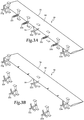
- Propulsion for wing member 12 is provided by a plurality of unmanned aircraft systems depicted as seven independent unmanned aircraft systems 22a, 22b, 22c, 22d, 22e, 22f, 22g that are operably coupled to leading edge 14 of wing member 12.
- Each unmanned aircraft system 22a-22g may be connected to wing member 12 using a magnetic coupling, which may utilize permanent magnets and/or electromagnets having opposite poles to create a strong magnetic attraction therebetween.
- the tail section of each unmanned aircraft system 22a-22g may have extending therefrom a permanent magnet that is operable to mate with or dock within an electromagnetic coil of wing member 12 that is energized responsive to current flow controlled by the electrical system and flight control system 18 of wing member 12.
- the illustrated configuration represents the connected flight mode of unmanned aircraft systems 22a-22g, wherein at least some of unmanned aircraft systems 22a-22g provide propulsion to wing member 12 to enable aircraft system 10 to fly.
- unmanned aircraft systems 22a-22g are operable to provide forward thrust such that aircraft system 10 can operate in a forward flight mode.
- unmanned aircraft systems 22a-22g are operable to provide vertical thrust such that aircraft system 10 can operate in a vertical takeoff and landing flight mode.
- Aircraft system 10 may operate in orientations between vertical takeoff and landing fight mode and forward flight mode and is operable to transition from vertical takeoff and landing fight mode to forward flight mode as well as from forward flight mode to vertical takeoff and landing fight mode.
- struts 24a, 24b may be permanently attached to wing member 12 and preferably stowed during flight.
- struts 24a, 24b may be jettisonable from wing member 12 after takeoff or may serve as ground support only such that aircraft system 10 separates from struts 24a, 24b upon takeoff.
- Flight control system 18 In the connected flight mode, the operation of unmanned aircraft systems 22a-22g is preferably controlled by flight control system 18 of wing member 12.
- Flight control system 18 may be a digital flight control system disposed with wing member 12 and may be implemented as a redundant or triply redundant system to improve the overall safety and reliability of aircraft system 10 in the event of a failure in flight control system 18.
- Flight control system 18 preferably includes non-transitory computer readable storage media including a set of computer instructions executable by processors for controlling the operation of aircraft system 10 including unmanned aircraft systems 22a-22g when in connected flight mode.
- Flight control system 18 may be implemented on one or more general-purpose computers, special purpose computers or other machines with memory and processing capability.
- flight control system 18 may include one or more memory storage modules including, but is not limited to, internal storage memory such as random access memory, non-volatile memory such as read only memory, removable memory such as magnetic storage memory, optical storage, solid-state storage memory or other suitable memory storage entity.
- Flight control system 18 may be a microprocessor-based system operable to execute program code in the form of machine-executable instructions.
- flight control system 18 may be selectively connectable to other computer systems via a proprietary encrypted network, a public encrypted network, the Internet or other suitable communication network that may include both wired and wireless connections.
- flight control system 18 communicates via data communications network 20 with the flight control systems of each unmanned aircraft systems 22a-22g such that each unmanned aircraft systems 22a-22g may be individually and independently controlled and operated. Flight control system 18 may autonomously control all aspects of flight operations for aircraft system 10. Alternatively or additionally, flight control system 18 may be operable to communicate with remote systems via a wireless communications protocol such that some or all aspects of flight operations for aircraft system 10 may be remotely controlled. Unmanned aircraft systems 22a-22g may be multirole UAS having a precision digital flight control and navigation system and the ability for swarm networking and cooperation.
- unmanned aircraft systems 22a-22g are self-powered, do not carry a human operator, use aerodynamic forces to provide vehicle lift, are autonomously and/or remotely operated, may be expendable or recoverable and may carry lethal or nonlethal payloads.
- Unmanned aircraft systems 22a-22g may be used in military, commercial, scientific, recreational and other applications.
- groups of unmanned aircraft systems 22a-22g may be networked together such that they are capable of cooperating with one another and exhibiting swarm behavior including, for example, the ability to dynamically adapt responsive to changing conditions or parameters, the ability for group coordination, distributed control, distributed tactical group planning, distributed tactical group goals, distributed strategic group goals and/or fully autonomous swarming.
- unmanned aircraft systems 22a-22g could be reconnaissance aircraft while other of unmanned aircraft systems 22a-22g could be attack aircraft.
- unmanned aircraft systems 22a-22g using internal flight control systems and networked communications, could cooperate together during missions detached from wing member 12 then periodically reconnect with wing member 12 to exchange information such as data collected during the mission and instructions for the next mission as well as to recharge batteries within unmanned aircraft systems 22a-22g.
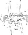
- unmanned aircraft system 22a including a generally cylindrical fuselage 28 and a tail section 30 including stabilizers 30a, 30b.
- Fuselage 28 includes a forward rotor station 32 and an aft rotor station 34.
- a forward rotor assembly 36 is positioned proximate forward rotor station 32.
- forward rotor assembly 36 includes a rotor hub 38 having three extensions, only extensions 38a, 38b being visible in the figures.
- Forward rotor assembly 36 also includes three rotor blades 40a, 40b, 40c each of which has a respective support arm, only support arms 42a, 42b being visible in the figures.
- rotor blade 40a is disclosed in greater detail.
- Rotor blade 40a is substantially similar to rotor blades 40b, 40c therefore, for sake of efficiency, certain features will be disclosed only with regard to rotor blade 40a.
- support arm 42a extends generally perpendicularly from a lower surface of rotor blade 40a.
- Support arm 42a includes an opening 44a and a bearing 46a. Opening 44a is operable to receive a pin therethrough to pivotably couple support arm 42a to extension 38a forming joint 48a. A similar joint is formed between each support arm and the respective extension, only joints 48a, 48b being visible in the figures.
- bearing 46a has a generally spherical surface and may be a static bearing or a rotatable bearing, only bearings 46a, 46b being visible in the figures.
- Support arm 42a includes a length 50a from the lower surface of rotor blade 40a to the center of opening 44a and a length 52a from the center of opening 44a to the end of bearing 46a.
- an aft rotor assembly 56 is positioned proximate aft rotor station 34.
- aft rotor assembly 56 includes a rotor hub 58 having three extensions, only extensions 58a, 58b being visible in the figures.
- Aft rotor assembly 56 also includes three rotor blades 60a, 60b, 60c each of which has a respective arm, only arm 62a being visible in the figures.
- rotor blade 60a is disclosed in greater detail. Rotor blade 60a is substantially similar to rotor blades 60b, 60c therefore, for sake of efficiency, certain features will be disclosed only with regard to rotor blade 60a.
- arm 62a extends generally perpendicularly from a lower surface of rotor blade 60a.
- Arm 62a includes an opening 64a and a tab 66a having an opening 70a. Opening 64a is operable to receive a pin therethrough to pivotably couple arm 62a to extension 58a forming joint 68a.
- a similar joint is formed between each arm and the respective extension, only joint 68a being visible in the figures.
- tab 66a extends from arm 62a at an angle of approximately 45 degrees.
- Arm 62a includes a length 72a from the lower surface of rotor blade 60a to the center of opening 64a.
- forward rotor assembly 36 and aft rotor assembly 56 are operable to rotate about a fixed shaft 74 that has a central passageway that contains a wiring harness including electrical and data communication lines.
- electrical communication lines supply battery power and data communication lines supply commands from electronics package 76 to a forward motor 78 and an aft motor 80 to enable independent operation of forward rotor assembly 36 and aft rotor assembly 56, as discussed herein, including operating forward rotor assembly 36 and aft rotor assembly 56 in counter rotation as indicated by the motion arrows in figure 2A .
- Electronics package 76 includes one or more rechargeable batteries, the digital flight control system and other computing systems required for the specific missions conducted by unmanned aircraft system 22a.
- unmanned aircraft system 22a is a surveillance drone including a sensor system 82 located in the nose of fuselage 28.
- Sensor system 82 may include positioning sensors, attitude sensors, speed sensors, environmental sensors, temperature sensors, target sensors and the like.
- sensor system 82 may include optical surveillance systems such as a spherical camera and/or a light detection and ranging module that may be pointed at a target of interest.
- both electrical and data communication lines will pass from electronics package 76 to sensor system 82 via the central passageway of shaft 74.
- Electronics package 76 preferably includes computing elements such as non-transitory computer readable storage media that include computer instructions executable by processors for controlling the flight operation of unmanned aircraft system 22a and surveillance operations of unmanned aircraft system 22a.
- the computing elements may be implemented on one or more general-purpose computers, special purpose computers or other machines with memory and processing capability.
- the computing elements may include one or more memory storage modules including, but is not limited to, internal storage memory such as random access memory, non-volatile memory such as read only memory, removable memory such as magnetic storage memory, optical storage, solid-state storage memory or other suitable memory storage entity.
- the computing elements may include microprocessor-based systems operable to execute program code in the form of machine-executable instructions.
- the computing elements may be selectively connectable to other computer systems via a proprietary encrypted network, a public encrypted network, the Internet or other suitable communication network that may include both wired and wireless connections.
- unmanned aircraft system 22a including a docking assembly 84 operably coupled to electronics package 76.
- docking assembly 84 included a magnetic element, at least one electrical connection and at least one data connection.
- Docking assembly 84 is operable to couple with a docking probe 86 that may be extended from wing member 12 during docking operations.
- docking probe 86 is a semi-rigid member that may be extended from wing member 12 (see figure 3C ) and may be formed from fiberglass or carbon. Linear actuators may be operable to extend and retract docking probe 86 from wing member 12.
- docking probe 86 may include a conical receptacle to aid in guiding docking assembly 84 into connection with docking probe 86.
- Docking probe 86 preferably includes a magnetic element, at least one electrical connection and at least one data connection.
- docking assembly 84 includes a permanent magnet having a passageway therethrough for containing electrical and data communication lines that are coupled with the at least one electrical connection and the at least one data connection of docking assembly 84.
- Docking assembly 84 is designed to be received within an opening 88 of docking probe 86.
- docking probe 86 includes an electromagnetic coil that is energized responsive to current flow controlled by the electrical system and flight control system 18 of wing member 12.
- a strong magnetic connection may be achieved in this manner, which may be maintained to prevent separation of unmanned aircraft system 22a from wing member 12.
- a mechanical locking member or other system may be used to securably couple unmanned aircraft system 22a to wing member 12 during connected flight mode.
- the electrical and data connections are formed therebetween to enable wing member 12 to resupply unmanned aircraft system 22a including, for example, recharging the batteries in electronics package 76 and providing additional or new data to the flight control system and mission control system of unmanned aircraft system 22a.
- the flight control system and mission control system of unmanned aircraft system 22a may upload data to computer systems of wing member 12.
- unmanned aircraft system 22a has been depicted and described as having a docking assembly in a particular location that has particular functionality, it should understood by those having ordinary skill in the art that an unmanned aircraft system of the present disclosure could have a docking assembly in alternate locations, such as extending forward from the nose, and/or a docking assembly with other capabilities, such as having nonmagnetic coupling capabilities.
- forming the electrical and data connections between an unmanned aircraft system of the present disclosure and wing member 12 may be independent of the process of coupling the docking assembly with the docking probe.
- an unmanned aircraft system of the present disclosure could dock with a wing member without the use of a docking probe that extends from the wing member.
- sequencing cam 90 is positioned between forward rotor assembly 36 and aft rotor assembly 56.
- Sequencing cam 90 is disposed on and is rotatable about fixed shaft 74.
- sequencing cam 90 has a generally cylindrical shelf 92 and a guide surface 94.
- Guide surface 94 has a profile in the form of an arc corresponding to approximately 90 degrees of a circle having a radius approximately equal to the length 52a of support arm 42a. This shape enables the bearings of the support arms to remain in contact with guide surface 94 during folding and rising operations of rotor blades 40a, 40b, 40c, as discussed herein.
- Sequencing cam 90 is coupled to and rotates with aft rotor assembly 56.
- sequencing cam 90 includes three lugs, only lugs 90a, 90b being visible in the figures, that are each rotatably coupled to one end of a linkage, only linkages 96a, 96b being visible in the figures.
- the other end of each linkage is rotatably coupled to a respective tab of an arm of rotor blades 60a, 60b, 60c forming a joint therebetween, only joint 98a being visible in the figures.
- unmanned aircraft system 22b is preferably in connected flight mode with wing member 12 after, for example, transitioning to a forward flight mode from a vertical takeoff and landing flight mode.
- wing member 12 As the thrust requirement for forward flight is reduced compared to vertical takeoff, propulsion from all of unmanned aircraft systems 22a-22g (see figure 3A ) may no longer be required.
- certain of the unmanned aircraft systems 22a-22g such as unmanned aircraft system 22b, may be shut down.
- forward motor 78 is rotating forward rotor assembly 36 in a counter clockwise direction as viewed from in front of unmanned aircraft system 22b and as indicated by the motion arrows.
- aft motor 80 is rotating aft rotor assembly 56 in a clockwise direction as viewed from in front of unmanned aircraft system 22b and as indicated by the motion arrows.
- rotor blades 40a, 40b, 40c have a positive angle of attack when rotated in the counter clockwise direction
- rotor blades 40a, 40b, 40c are aerodynamically actuated to an operating or deployed configuration in which rotor blades 40a, 40b, 40c extend generally radially outward relative to fuselage 28.
- rotor blades 60a, 60b, 60c have a positive angle of attack when rotated in the clockwise direction
- rotor blades 60a, 60b, 60c are aerodynamically actuated to an operating or deployed configuration in which rotor blades 60a, 60b, 60c extend generally radially outward relative to fuselage 28.
- forward motor 78 rotates forward rotor assembly 36 above a predetermined speed
- rotor blades 40a, 40b, 40c remain in the deployed configuration.
- aft motor 80 rotates aft rotor assembly 56 above a predetermined speed
- rotor blades 60a, 60b, 60c remain in the deployed configuration.
- rotor blades 40a, 40b, 40c remain in the deployed configuration even if forward motor 78 ceases to rotate forward rotor assembly 36 above the predetermined speed as cylindrical shelf 92 of sequencing cam 90 props the support arms of rotor blades 40a, 40b, 40c and prevents rotor blades 40a, 40b, 40c from pivoting relative to rotor hub 38 as the bearings are radially supported by cylindrical shelf 92.
- sequencing cam 90 In the initial phase of pivoting of rotor blades 60a, 60b, 60c, sequencing cam 90 remains substantially fixed translationally relative to fixed shaft 74 due to the path taken by the linkages and as indicated by the lack of translationally movement of sequencing cam 90 between figures 2D and 2E . Thus, sequencing cam 90 continues to prop the support arms of rotor blades 40a, 40b, 40c and prevent rotor blades 40a, 40b, 40c from pivoting relative to rotor hub 38 as the bearings remain radially supported by cylindrical shelf 92.
- This motion may be described as translating sequencing cam 90 from an extended orientation to a retracted orientation wherein sequencing cam 90 no longer props the support arms of rotor blades 40a, 40b, 40c or prevents rotor blades 40a, 40b, 40c from pivoting relative to rotor hub 38 as the bearings are no longer radially supported by cylindrical shelf 92. It is noted that as long as forward motor 78 rotates forward rotor assembly 36 above a predetermined speed, rotor blades 40a, 40b, 40c remain in the deployed configuration as indicated by the motion arrows in figure 2F .
- rotor blades 40a, 40b, 40c occupy a radial space that is different than the radial space occupied by rotor blades 60a, 60b, 60c and namely a radial space having a greater radial distance from fuselage 28.
- rotor blades 40a, 40b, 40c and rotor blades 60a, 60b, 60c avoid interference when rotor blades 40a, 40b, 40c and rotor blades 60a, 60b, 60c are in the stowed configurations.
- rotor blades 40a, 40b, 40c complete the transition from the stowed configuration to the deployed configuration, as best seen in figure 2F .
- rotor blades 40a, 40b, 40c pivot relative to rotor hub 38 at the respective joints therebetween with the bearings remaining in contact with guide surface 94 of sequencing cam 90 until rotor blades 40a, 40b, 40c reach the deployed configuration at which time the bearings may loose contact with guide surface 94 of sequencing cam 90.
- power to aft motor 80 may now commence causing rotation of aft rotor assembly 56, as indicated by the motion arrows, which in turn causes rotor blades 60a, 60b, 60c to begin rising responsive to aerodynamic actuation.
- rotor blades 60a, 60b, 60c rise, rotor blades 60a, 60b, 60c pivot relative to rotor hub 58 at the respective joints therebetween.
- the pivoting motion is coupled to sequencing cam 90 via the linkages causing sequencing cam 90 to translate forward relative to fixed shaft 74.
- sequencing cam 90 This motion may be described as translating sequencing cam 90 from the retracted orientation to the extended orientation wherein sequencing cam 90 now props the support arms of rotor blades 40a, 40b, 40c and prevents rotor blades 40a, 40b, 40c from pivoting relative to rotor hub 38 as the bearings are radially supported by cylindrical shelf 92.
- rotor blades 60a, 60b, 60c complete the transition from the stowed configuration to the deployed configuration, as best seen in figure 2D .
- rotor blades 60a, 60b, 60c pivot relative to rotor hub 58 at the respective joints therebetween.
- the pivoting motion is coupled to sequencing cam 90, however, due to the path taken by the linkages, sequencing cam 90 experience little or no additional translationally movement as indicated by the similarity in location of sequencing cam 90 in figures 2D and 2E .
- sequencing cam 90 continues to prop the support arms of rotor blades 40a, 40b, 40c and prevent rotor blades 40a, 40b, 40c from pivoting relative to rotor hub 38 as the bearings are radially supported by cylindrical shelf 92.
- rotor blades 40a, 40b, 40c and rotor blades 60a, 60b, 60c avoid interference when rotor blades 40a, 40b, 40c and rotor blades 60a, 60b, 60c are transitioned from the stowed configurations to the deployed configurations.
- aircraft system 10 including a wing member 12 having a leading edge 14, a trailing edge 16 and an airfoil cross-section that generates lift responsive to the forward airspeed of aircraft system 10.
- wing member 12 houses computer systems such as a flight control system 18 and a data communications network 20 (see figure 1A ), a battery system, an electrical communications network, liquid fuel tanks and an electrical generator system and other systems for supporting missions relating to aircraft system 10.
- Propulsion for wing member 12 is provided by unmanned aircraft systems 22a-22g that are operably coupled to leading edge 14 of wing member 12.
- the illustrated configuration represents the connected flight mode of unmanned aircraft systems 22a-22g, wherein at least some of unmanned aircraft systems 22a-22g provide propulsion to wing member 12 to enable aircraft system 10 to fly.
- aircraft system 10 is designed to enable high endurance flights by carrying an energy source and by generating additional energy with wing member 12. This enables wing member 12 to supply and resupply energy to unmanned aircraft systems 22a-22g such that unmanned aircraft systems 22a-22g can perform numerous and sequential missions detached from wing member 12. In addition, while in connected flight mode, unmanned aircraft systems 22a-22g are operable to provide propulsion to wing member 12. To further enable high endurance flights of aircraft system 10, when maximum thrust is not required, certain of unmanned aircraft systems 22a-22g may be shut down to conserve energy.
- unmanned aircraft systems 22a, 22d, 22g are operating to provide forward thrust for aircraft system 10 while unmanned aircraft systems 22b, 22c, 22e, 22f have been shut down using, for example, the rotor sequencing protocol discussed herein to avoid rotor blade interference.
- Flight control system 18 of wing member 12 is operable to determine which and how many of the unmanned aircraft systems 22a-22g should be operated during forward flight mode based upon mission parameters, charge status of the unmanned aircraft systems, environmental conditions and the like. As discussed herein, in connected flight mode, all aspects of the operation of unmanned aircraft systems 22a-22g are preferably controlled by flight control system 18 of wing member 12.
- Such command and control information is communicated to unmanned aircraft systems 22a-22g via data communications network 20 of wing member 12 (see figure 1A ). It is noted that flight control system 18 may autonomously control all aspects of flight operations for aircraft system 10. Alternatively or additionally, flight control system 18 may be operable to communicate with remote systems via a wireless communications protocol such that some or all aspects of flight operations for aircraft system 10 may be remotely controlled.
- unmanned aircraft systems 22a-22g may be multirole UAS having precision digital flight control and navigation systems providing independent flight modes for unmanned aircraft systems 22a-22g when unmanned aircraft systems 22a-22g are detached or remote from wing member 12.
- unmanned aircraft systems 22b, 22c, 22e, 22f are reconnaissance aircraft operating, for example, light detection and ranging modules while unmanned aircraft systems 22a, 22d, 22g are attack aircraft carrying, for example, air-to-ground missiles such as Hellfire or JAGM missiles.
- wing member 12 may provide unmanned aircraft systems 22b, 22c, 22e, 22f with mission information while unmanned aircraft systems 22b, 22c, 22e, 22f are shut down.
- Unmanned aircraft systems 22b, 22c, 22e, 22f may now commence operations using, for example, the rotor sequencing protocol discussed herein to avoid rotor blade interference. Thereafter, wing member 12 performs an aerial launch of unmanned aircraft systems 22b, 22c, 22e, 22f, as best seen in figure 3B . For example, in performing the aerial launch, wing member 12 may shut down the current flow through the respective electromagnetic coils securably coupling unmanned aircraft systems 22b, 22c, 22e, 22f to wing member 12 such that the thrust generated by unmanned aircraft systems 22b, 22c, 22e, 22f separates unmanned aircraft systems 22b, 22c, 22e, 22f from wing member 12. Detached from wing member 12, unmanned aircraft systems 22b, 22c, 22e, 22f each operate in independent flight mode during which time unmanned aircraft systems 22b, 22c, 22e, 22f may cooperate together using networked communications to achieve mission goals.
- unmanned aircraft systems 22b, 22c, 22e, 22f perform an aerial survey of potential military targets which are preferably sufficiently remote from aircraft system 10 such that aircraft system 10 can avoid detection. Thereafter, unmanned aircraft systems 22b, 22c, 22e, 22f may return to wing member 12 and reconnect therewith via an aerial recovery process. As illustrated in figure 3C , unmanned aircraft systems 22c, 22e have been aerially recovered by wing member 12 and are shut down. Unmanned aircraft systems 22b, 22f are currently being aerially recovered by wing member 12 using, for example, the technique described herein of the wing member 12 extending docking probes 86b, 86f to magnetically couple with respective docking assemblies of unmanned aircraft systems 22b, 22f (see figure 2A ).
- docking probes 86b, 86f preferably include magnetic elements, at least one electrical connection and at least one data connection that couple with corresponding magnetic elements, electrical connections and data connections of unmanned aircraft systems 22b, 22f.
- wing member 12 may retract unmanned aircraft systems 22b, 22f into further engagement with wing member 12.
- unmanned aircraft systems 22b, 22f may be shut down such that aircraft system 10 returns to the state depicted in figure 3A , which is considered to be connected flight mode even when selected unmanned aircraft systems are shut down.
- Computer systems within wing member 12 may now receive an upload of the information obtained by unmanned aircraft systems 22b, 22c, 22e, 22f during the reconnaissance missions.
- wing member 12 may resupply unmanned aircraft systems 22b, 22c, 22e, 22f with instructions for the next mission as well as recharge batteries within unmanned aircraft systems 22b, 22c, 22e, 22f.
- it may be desirable to send unmanned aircraft systems 22b, 22c, 22e, 22f on another set of reconnaissance missions to perform additional aerial surveys of potential military targets.
- wing member 12 would perform another aerial launch of unmanned aircraft systems 22b, 22c, 22e, 22f, as best seen in figure 3B
- unmanned aircraft systems 22b, 22c, 22e, 22f would perform the reconnaissance missions in independent flight mode
- wing member 12 would perform another aerial recovery of unmanned aircraft systems 22b, 22c, 22e, 22f, as best seen in figure 3C
- wing member 12 would exchange information with and resupply unmanned aircraft systems 22b, 22c, 22e, 22f, as best seen in figure 3A .
- unmanned aircraft systems 22a, 22d, 22g may be desirable to send unmanned aircraft systems 22a, 22d, 22g on an attack mission relating to one or more of the identified military targets.
- unmanned aircraft systems 22b, 22c, 22e, 22f commence operations using, for example, the rotor sequencing protocol discussed herein to avoid rotor blade interference.
- wing member 12 performs an aerial launch of unmanned aircraft systems 22a, 22d, 22g, as best seen in figure 3D . Detached from wing member 12, unmanned aircraft systems 22a, 22d, 22g each operate in independent flight mode during which time unmanned aircraft systems 22a, 22d, 22g may cooperate together using networked communications to achieve mission goals.
- unmanned aircraft systems 22a, 22d, 22g may fly in formation to the location of the military target of interest and perform the desired military operation such as deploying air-to-ground missiles. Thereafter, unmanned aircraft systems 22a, 22d, 22g may return to wing member 12 for an aerial recovery. Following the attack mission, it may be desirable to perform another aerial survey using unmanned aircraft systems 22b, 22c, 22e, 22f, as discussed herein.
- Aircraft 110 includes a fuselage 112 having a forward portion 114 and an aft portion 116.
- Forward portion 114 of fuselage 112 includes two rotor stations 118, 120.
- a rotor assembly 122 is located at rotor station 118 and a rotor assembly 124 is located at rotor station 120.
- Rotor assembly 122 includes a rotor hub 122a having rotor blades 122b, 122c, 122d coupled thereto.
- rotor assembly 124 includes a rotor hub 124a having rotor blades 124b, 124c, 124d coupled thereto.
- tailboom assembly 126 extends from aft portion 116 of fuselage 112.
- tailboom assembly 126 includes a plurality of landing members 128a, 128b, 128c, 128d such as fixed or retractable skid members or shock absorbing members such as a pneumatic shock struts or mechanical spring assemblies.
- Landing members 128a-128d may also include wheels (not pictured) to assist in ground maneuvers.
- Tailboom assembly 126 includes a plurality of control surfaces 130a, 130b, 130c, 130d that can be used during forward flight as rudders for yaw control and/or elevators for pitch control depending upon the orientation of aircraft 110.
- aircraft 110 includes a sensor system 140 located in the nose of fuselage 112.
- Sensor system 140 may include positioning sensors, attitude sensors, speed sensors, environmental sensors, temperature sensors, target sensors and the like.
- sensor system 140 may include surveillance systems such as a spherical camera that may be pointed at any target of interest forward of rotor assembly 122.
- aircraft 110 may be an unmanned aircraft system that is self-powered, does not carry a human operator, uses aerodynamic forces to provide vehicle lift, is autonomously and/or remotely operated, may be expendable or recoverable and may carry lethal or nonlethal payloads. In such embodiments, aircraft 110 may be used in military, commercial, scientific, recreational and other applications.
- groups of aircraft may be networked together such that they are capable of cooperating with one another and exhibiting swarm behavior including, for example, the ability to dynamically adapt responsive to changing conditions or parameters, the ability for group coordination, distributed control, distributed tactical group planning, distributed tactical group goals, distributed strategic group goals and/or fully autonomous swarming.
- one or more aircraft 110 may engage a target by launching missiles from aft portion 116 of fuselage 112, when aircraft 110 is in forward flight mode.
- aircraft 110 could be a manned aircraft operable for onboard pilot control over some or all aspects of flight operations.
- aircraft 110 has a storage mode in which aircraft 110 has a small ground geometry.
- rotor blades 122b, 122c, 122d of rotor assembly 122 are foldable relative to rotor hub 122a such that rotor blades 122b, 122c, 122d extend in the aft direction generally parallel to fuselage 112.
- rotor blades 124b, 124c, 124d of rotor assembly 124 are foldable relative to rotor hub 124a such that rotor blades 124b, 124c, 124d extend in the aft direction generally parallel to fuselage 112.
- Rotor blades 122b, 122c, 122d may be lockable in the illustrated stowed configuration.
- rotor blades 124b, 124c, 124d may be lockable in the illustrated stowed configuration.
- aircraft 110 occupies minimal ground space and has a suitable geometry for crating and/or palletizing for storage and/or transportation with other similar aircraft 110.
- aircraft 110 has a vertical takeoff and landing flight mode in which aircraft 110 has a generally vertical attitude.
- rotor blades 122b, 122c, 122d and rotor blades 124b, 124c, 124d have risen from the stowed configuration to the deployed configuration extending generally radially outward from fuselage 112 using, for example, the rotor sequencing protocol discussed herein to avoid blade interference.
- rotor blades 122b, 122c, 122d and rotor blades 124b, 124c, 124d have generally symmetrical airfoils, little or no twist and a fixed pitch. It should be understood, however, that rotor blades 122b, 122c, 122d and rotor blades 124b, 124c, 124d could have other blade designs that are known to those having ordinary skill in the art.
- rotor assembly 122 rotates in a counter clockwise direction, as indicated by directional motion arrows 144
- rotor assembly 124 rotates in a clockwise direction, as indicated by directional motion arrows 146.
- rotor assemblies 122, 124 are preferably operated by independent electrical motors that enable rotor assemblies 122, 124 to counter rotate preferably resulting in substantial torque matching of aircraft 110 in flight modes. In this manner, aircraft 110 has vertical thrust and is stable relative to rotation about longitudinal fuselage axis 142 in vertical takeoff and landing mode including during hover operations.
- aircraft 110 has a forward flight mode in which aircraft 110 has a generally horizontal attitude.
- rotor blades 122b, 122c, 122d of rotor assembly 122 are in the deployed configuration generally radially extending from fuselage 112 and are rotating in a counter clockwise direction, when viewed from the in front of aircraft 110, as indicated by directional motion arrows 144.
- rotor blades 124b, 124c, 124d of rotor assembly 124 are in the deployed configuration generally radially extending from fuselage 112 and are rotating in a clockwise direction, when viewed from the in front of aircraft 110, as indicated by directional motion arrows 146.
- aircraft 110 can transition from vertical takeoff and landing flight mode to forward flight mode and from forward flight mode to vertical takeoff and landing flight mode. For example, after completing a mission, aircraft 110 preferably returns to a predetermined location and transitions from forward flight mode to vertical takeoff and landing flight mode. Aircraft 110 can then execute a landing on landing members 128a-128d.
- rotation of rotor blades 122b, 122c, 122d and rotor blades 124b, 124c, 124d may be shut down such that rotor blades 122b, 122c, 122d and rotor blades 124b, 124c, 124d fold from the deployed configurations to the stowed configurations using, for example, the rotor sequencing protocol discussed herein to avoid blade interference.
Landscapes
- Engineering & Computer Science (AREA)
- Aviation & Aerospace Engineering (AREA)
- Mechanical Engineering (AREA)
- Remote Sensing (AREA)
- Transmission Devices (AREA)
- Turbine Rotor Nozzle Sealing (AREA)
Claims (16)
- Flugzeug (22a), umfassend:einen Rumpf (28), der erste (32) und zweite (34) Rotorstationen aufweist;eine erste Rotorbaugruppe (36), die nahe der ersten Rotorstation (32) positioniert ist, wobei die erste Rotorbaugruppe (36) eine erste Rotornabe (38) und erste Rotorblätter (40a, 40b, 40c) einschließt, die Stützarme (42a, 42b) aufweisen, die schwenkbar mit der ersten Rotornabe (38) gekoppelt sind;eine zweite Rotorbaugruppe (56), die nahe der zweiten Rotorstation (34) positioniert ist, wobei die zweite Rotorbaugruppe (56) eine zweite Rotornabe (58) und zweite Rotorblätter (60a, 60b, 60c) einschließt, die schwenkbar mit der zweiten Rotornabe (56) gekoppelt sind; undeinen Nocken (90), der zwischen den ersten (32) und zweiten (34) Rotorstationen positioniert ist und mit den zweiten Rotorblättern (60a, 60b, 60c) gekoppelt ist;wobei die ersten Rotorblätter (40a, 40b, 40c) und die zweiten Rotorblätter (60a, 60b, 60c) aufgestellte Konfigurationen, die sich allgemein radial von dem Rumpf (28) erstrecken, und verstaute Konfigurationen, die sich allgemein parallel zu dem Rumpf (28) erstrecken, aufweisen;wobei der Nocken (90) eine erste Orientierung aufweist, wenn die zweiten Rotorblätter (60a, 60b, 60c) in der verstauten Konfiguration sind; undwobei der Nocken (90) eine zweite Orientierung aufweist, wenn die zweiten Rotorblätter (60a, 60b, 60c) in der aufgestellten Konfiguration sind, in der der Nocken (90) die Stützarme (42a, 42b) der ersten Rotorblätter (40a, 40b, 40c) abstützt, was Überführung der ersten Rotorblätter (40a, 40b, 40c) von der aufgestellten Konfiguration zu der verstauten Konfiguration verhindert.
- Flugzeug (22a) nach Anspruch 1, wobei sich die erste Rotorstation (32) vor der zweiten Rotorstation (34) befindet.
- Flugzeug (22a) nach Anspruch 1 oder Anspruch 2, wobei die erste Rotorbaugruppe (36) weiter mindestens zwei erste Rotorblätter (40a, 40b, 40c) umfasst und die zweite Rotorbaugruppe (56) weiter mindestens zwei zweite Rotorblätter (60a, 60b, 60c) umfasst.
- Flugzeug (22a) nach Anspruch 1 oder Anspruch 2 oder Anspruch 3, wobei Überführungen von der verstauten Konfiguration zu der aufgestellten Konfiguration der ersten Rotorblätter (40a, 40b, 40c) aerodynamisch betätigt werden und wobei Überführungen von der verstauten Konfiguration zu der aufgestellten Konfiguration der zweiten Rotorblätter (60a, 60b, 60c) aerodynamisch betätigt werden.
- Flugzeug (22a) nach Anspruch 1 oder einem der vorstehenden Ansprüche, wobei die erste Rotorbaugruppe (36) relativ zu der zweiten Rotorbaugruppe (56) entgegengesetzt rotiert.
- Flugzeug (22a) nach Anspruch 1 oder einem der vorstehenden Ansprüche, weiter umfassend einen ersten Motor (78), der dafür betreibbar ist, die erste Rotornabe (38) zu rotieren, und einen zweiten Motor (80), der dafür betreibbar ist, die zweite Rotornabe (58) zu rotieren, und wobei optional oder vorzugsweise Betrieb des ersten Motors (78) von Betrieb des zweiten Motors (80) unabhängig ist.
- Flugzeug (22a) nach Anspruch 1 oder einem der vorstehenden Ansprüche, wobei der Nocken (90) weiter eine allgemein zylindrische Ablage (92) umfasst, die die Stützarme (42a, 42b) der ersten Rotorblätter (40a, 40b, 40c) abstützt, wenn der Nocken (90) in der zweiten Orientierung ist.
- Flugzeug (22a) nach Anspruch 1 oder einem der vorstehenden Ansprüche, wobei der Nocken (90) weiter eine Führungsoberfläche (94) für die Stützarme (42a, 42b) der ersten Rotorblätter (40a, 40b, 40c) umfasst, wenn die ersten Rotorblätter (40a, 40b, 40c) zwischen der aufgestellten Konfiguration und der verstauten Konfiguration überführt werden.
- Flugzeug (22a) nach Anspruch 8, wobei:(i) die Führungsoberfläche (4) des Nockens (90) weiter ein Profil umfasst, das einen Bogen eines Kreises einschließt; und/oder(ii) die Führungsoberfläche (94) des Nockens (90) weiter ein Profil umfasst, das einen Bogen einschließt, der näherungsweise 90 Grad eines Kreises entspricht.
- Flugzeug (22a) nach Anspruch 1 oder einem der vorstehenden Ansprüche, wobei der Nocken (90) mit der zweiten Rotorbaugruppe (56) rotiert.
- Flugzeug (22a) nach Anspruch 1 oder einem der vorstehenden Ansprüche, wobei der Nocken (90) zwischen der zweiten Orientierung und der ersten Orientierung reagierend darauf translatiert, dass die zweiten Rotorblätter (60a, 60b, 60c) zwischen der aufgestellten Konfiguration und der verstauten Konfiguration überführt werden.
- Flugzeug (22a) nach Anspruch 1 oder einem der vorstehenden Ansprüche, wobei die zweite Orientierung des Nockens (90) vor der ersten Orientierung des Nockens (90) ist.
- Verfahren eines Sequenzierens von Rotorblättern eines Flugzeugs (22a), das einen Rumpf (28), eine erste Rotorbaugruppe (36), die eine erste Rotornabe (38) und erste Rotorblätter (40a, 40b, 40c) aufweist, eine zweite Rotorbaugruppe (56), die eine zweite Rotornabe (58) und zweite Rotorblätter (60a, 60b, 60c) aufweist, und einen Nocken (90), der zwischen den ersten (38) und zweiten (58) Rotornaben positioniert ist und mit den zweiten Rotorblättern (60a, 60b, 60c) gekoppelt ist, aufweist, das Verfahren umfassend:Überführen der ersten Rotorblätter (40a, 40b, 40c) von einer verstauten Konfiguration, die sich allgemein parallel zu dem Rumpf (28) erstreckt, zu einer aufgestellten Konfiguration, die sich allgemein radial von dem Rumpf (28) erstreckt, durch Rotieren der ersten Rotornabe (38);Überführen der zweiten Rotorblätter (60a, 60b, 60c) von einer verstauten Konfiguration, die sich allgemein parallel zu dem Rumpf (28) erstreckt, zu einer aufgestellten Konfiguration, die sich allgemein radial von dem Rumpf (28) erstreckt, durch Rotieren der zweiten Rotornabe (58);Translatieren des Nockens (90) von einer ersten Orientierung zu einer zweiten Orientierung reagierend auf Überführen der zweiten Rotorblätter (60a, 60b, 60c); undVerhindern von Überführen der ersten Rotorblätter (40a, 40b, 40c) von der aufgestellten Konfiguration zu der verstauten Konfiguration durch Abstützen von Stützarmen (42a, 42b) der ersten Rotorblätter (40a, 40b, 40c) mit dem Nocken (90) in der zweiten Orientierung.
- Verfahren eines Sequenzierens von Rotorblättern eines Flugzeugs (22a), das einen Rumpf (28), eine erste Rotorbaugruppe (36), die eine erste Rotornabe (38) und erste Rotorblätter (40a, 40b, 40c) aufweist, eine zweite Rotorbaugruppe (56), die eine zweite Rotornabe (58) und zweite Rotorblätter (60a, 60b, 60c) aufweist, und einen Nocken (90), der zwischen den ersten (38) und zweiten (58) Rotornaben positioniert ist und mit den zweiten Rotorblättern (60a, 60b, 60c) gekoppelt ist, aufweist, das Verfahren umfassend:Rotieren der ersten Rotornabe (38) mit den ersten Rotorblättern (40a, 40b, 40c) in einer aufgestellten Konfiguration, die sich allgemein radial von dem Rumpf (28) erstreckt;Rotieren der zweiten Rotornabe (58) mit den zweiten Rotorblättern (60a, 60b, 60c) in einer aufgestellten Konfiguration, die sich allgemein radial von dem Rumpf (28) erstreckt;Verhindern von Überführen der ersten Rotorblätter (40a, 40b, 40c) von der aufgestellten Konfiguration zu einer verstauten Konfiguration, die sich allgemein parallel zu dem Rumpf (28) erstreckt, durch Abstützen von Stützarmen (42a, 42b) der ersten Rotorblätter (40a, 40b, 40c) mit dem Nocken (90) in einer zweiten Orientierung;Überführen der zweiten Rotorblätter (60a, 60b, 60c) von der aufgestellten Konfiguration zu einer verstauten Konfiguration, die sich allgemein parallel zu dem Rumpf (28) erstreckt, durch Stoppen von Rotation der zweiten Rotorblätter (60a, 60b, 60c);Aufhören von Abstützen der Stützarme (42a, 42b) der ersten Rotorblätter (40a, 40b, 40c) durch Translatieren des Nockens (90) von der zweiten Orientierung zu einer ersten Orientierung reagierend auf Überführen der zweiten Rotornabe (58); undÜberführen der ersten Rotorblätter (40a, 40b, 40c) von der aufgestellten Konfiguration zu der verstauten Konfiguration durch Stoppen von Rotation der ersten Rotornabe (38) nach Aufhören von Abstützen der Stützarme (42a, 42b).
- Verfahren nach Anspruch 13, wobei Überführen der ersten Rotorblätter (40a, 40b, 40c) von der verstauten Konfiguration zu der aufgestellten Konfiguration weiter aerodynamisches Betätigen der ersten Rotorblätter (40a, 40b, 40c) umfasst, und wobei Überführen der zweiten Rotorblätter (60a, 60b, 60c) von der verstauten Konfiguration zu der aufgestellten Konfiguration weiter aerodynamisches Betätigen der zweiten Rotorblätter (60a, 60b, 60c) umfasst; oder
Verfahren nach Anspruch 14, wobei Rotieren der ersten Rotornabe (38) mit den ersten Rotorblättern (40a, 40b, 40c) in den aufgestellten Konfigurationen weiter aerodynamisches Betätigen der ersten Rotorblätter (40a, 40b, 40c) umfasst, und wobei Rotieren der zweiten Rotornabe (58) mit den zweiten Rotorblättern (60a, 60b, 60c) in der aufgestellten Konfiguration weiter aerodynamisches Betätigen der zweiten Rotorblätter (60a, 60b, 60c) umfasst. - Verfahren nach Anspruch 13 oder Anspruch 14 oder Anspruch 15, sofern er von Anspruch 13 oder Anspruch 14 abhängig ist, weiter umfassend Rotieren des Nockens (90) mit der zweiten Rotorbaugruppe (56).
Applications Claiming Priority (1)
| Application Number | Priority Date | Filing Date | Title |
|---|---|---|---|
| US15/341,905 US10287010B2 (en) | 2016-11-02 | 2016-11-02 | Rotor sequencing for dual rotor aircraft |
Publications (2)
| Publication Number | Publication Date |
|---|---|
| EP3318489A1 EP3318489A1 (de) | 2018-05-09 |
| EP3318489B1 true EP3318489B1 (de) | 2018-09-26 |
Family
ID=59997186
Family Applications (1)
| Application Number | Title | Priority Date | Filing Date |
|---|---|---|---|
| EP17193869.9A Active EP3318489B1 (de) | 2016-11-02 | 2017-09-28 | Rotorsequenzierung fuer doppelrotorflugzeug |
Country Status (3)
| Country | Link |
|---|---|
| US (1) | US10287010B2 (de) |
| EP (1) | EP3318489B1 (de) |
| CN (1) | CN108016603B (de) |
Cited By (1)
| Publication number | Priority date | Publication date | Assignee | Title |
|---|---|---|---|---|
| US11851181B2 (en) | 2018-06-22 | 2023-12-26 | The Boeing Company | Self-aligning docking mechanism for an unmanned aerial vehicle (UAV) |
Families Citing this family (14)
| Publication number | Priority date | Publication date | Assignee | Title |
|---|---|---|---|---|
| US9434471B2 (en) * | 2005-04-14 | 2016-09-06 | Paul E Arlton | Rotary wing vehicle |
| US12240633B2 (en) * | 2004-04-14 | 2025-03-04 | Paul E. Arlton | Rotary wing vehicle |
| US12545444B2 (en) | 2013-05-21 | 2026-02-10 | Paul E. Arlton | Rotary wing vehicle |
| US20180281949A1 (en) * | 2015-09-09 | 2018-10-04 | Altus IP Limited | Systems and methods for stabilisation of aerial vehicles |
| US10272999B2 (en) * | 2015-12-15 | 2019-04-30 | Aerovel Corporation | Tail-sitter aircraft with legged undercarriage foldable to form rear fuselage |
| WO2018071592A2 (en) * | 2016-10-13 | 2018-04-19 | Alexander Poltorak | Apparatus and method for balancing aircraft with robotic arms |
| BR112020006858A2 (pt) | 2017-10-05 | 2020-10-06 | Overwerx Ltd. | material bélico aeronáutico remotamente controlável |
| CN108298064B (zh) * | 2017-11-09 | 2024-04-26 | 青岛兰道尔空气动力工程有限公司 | 非常规偏航控制系统 |
| US11827344B2 (en) * | 2020-12-09 | 2023-11-28 | Textron Innovations Inc. | Low noise ducted fan |
| CN113085462B (zh) * | 2021-04-23 | 2023-06-13 | 南京航空航天大学 | 一种跨介质无人机装置及其控制方法 |
| CN113942635A (zh) * | 2021-12-20 | 2022-01-18 | 深圳市高端无人机有限公司 | 一种共轴无人机 |
| AT526183A1 (de) * | 2022-06-13 | 2023-12-15 | Andreas Desch Dipl Ing | Drohne |
| DE102022117766A1 (de) | 2022-07-15 | 2024-01-18 | FlyPurrz GmbH | Senkrecht startendes Flugzeug |
| IT202200018594A1 (it) * | 2022-09-12 | 2024-03-12 | Phase Motion Control S P A | Dispositivo propulsore aeronautico |
Family Cites Families (11)
| Publication number | Priority date | Publication date | Assignee | Title |
|---|---|---|---|---|
| WO2003059735A2 (en) * | 2001-12-21 | 2003-07-24 | Arlton Paul E | Micro-rotocraft surveillance system |
| ES2504167T3 (es) | 2004-04-14 | 2014-10-08 | Paul E. Arlton | Vehículo de alas giratorias |
| GB2491129B (en) * | 2011-05-23 | 2014-04-23 | Blue Bear Systems Res Ltd | Air vehicle |
| US8985951B2 (en) * | 2011-12-13 | 2015-03-24 | Textron Innovations Inc. | Multiple-yoke main rotor assembly |
| KR102192821B1 (ko) * | 2014-11-04 | 2020-12-18 | 엘지전자 주식회사 | 드론 |
| US9828088B2 (en) * | 2014-11-05 | 2017-11-28 | Bell Helicopter Textron Inc. | Scissoring fold arrangement for dual plane four bladed rotor hubs |
| EP4610177A1 (de) * | 2014-11-10 | 2025-09-03 | Ascent Aerosystems Inc. | Unbemanntes fluggerät |
| CN204937484U (zh) * | 2015-09-07 | 2016-01-06 | 李嘉伟 | 一种用于小型无人航空飞行器的易拆装折叠式螺旋桨 |
| US10502188B2 (en) * | 2016-03-30 | 2019-12-10 | Lockheed Martin Corporation | Wind-powered recharging for a weight-shifting coaxial helicopter |
| US10407169B2 (en) * | 2016-08-30 | 2019-09-10 | Bell Textron Inc. | Aircraft having dual rotor-to-wing conversion capabilities |
| US10414492B2 (en) * | 2016-08-30 | 2019-09-17 | Bell Textron Inc. | Aircraft having rotor-to-wing conversion capabilities |
-
2016
- 2016-11-02 US US15/341,905 patent/US10287010B2/en active Active
-
2017
- 2017-09-28 EP EP17193869.9A patent/EP3318489B1/de active Active
- 2017-10-31 CN CN201711044484.XA patent/CN108016603B/zh not_active Expired - Fee Related
Non-Patent Citations (1)
| Title |
|---|
| None * |
Cited By (1)
| Publication number | Priority date | Publication date | Assignee | Title |
|---|---|---|---|---|
| US11851181B2 (en) | 2018-06-22 | 2023-12-26 | The Boeing Company | Self-aligning docking mechanism for an unmanned aerial vehicle (UAV) |
Also Published As
| Publication number | Publication date |
|---|---|
| EP3318489A1 (de) | 2018-05-09 |
| CN108016603B (zh) | 2020-11-03 |
| US20180118334A1 (en) | 2018-05-03 |
| US10287010B2 (en) | 2019-05-14 |
| CN108016603A (zh) | 2018-05-11 |
Similar Documents
| Publication | Publication Date | Title |
|---|---|---|
| US10287010B2 (en) | Rotor sequencing for dual rotor aircraft | |
| US10392109B2 (en) | Mutually symbiotic aircraft systems | |
| US11390381B1 (en) | In-flight reconfigurable hybrid unmanned aerial vehicle with swing arm for engaging or disengaging items | |
| EP3290338B1 (de) | Flugzeug mit fähigkeiten zur rotor-zu-flügel-umwandlung | |
| EP3290337B1 (de) | Flugzeug mit dualer rotor-flügel-umwandlungsfähigkeit | |
| CN110740933B (zh) | 带环形机翼的六自由度飞行器 | |
| EP3259184B1 (de) | Unbemanntes luftfahrzeug | |
| CA3096609C (en) | Convertible biplane aircraft for autonomous cargo delivery | |
| US10118687B1 (en) | Inflight connection of aircraft | |
| US10814973B2 (en) | Aircraft having M-wing and gull wing configurations | |
| US11479352B2 (en) | Tailsitting biplane aircraft having a coaxial rotor system | |
| US20200290737A1 (en) | Convertible Biplane Aircraft for Capturing Drones | |
| US11479353B2 (en) | Distributed elevon systems for tailsitting biplane aircraft | |
| US11650604B2 (en) | Yaw control systems for tailsitting biplane aircraft | |
| US11479354B2 (en) | Thrust vectoring coaxial rotor systems for aircraft | |
| US11643207B1 (en) | Aircraft for transporting and deploying UAVs | |
| US20110006151A1 (en) | Aerial recovery of small and micro air vehicles | |
| US11780576B1 (en) | Long-endurance aircraft having tiltable propulsion | |
| US11530035B2 (en) | VTOL aircraft having multiple wing planforms | |
| US20230091705A1 (en) | Convertible Staggerwing Aircraft having Optimized Hover Power | |
| Sampaio | Novel morphologies on flying robots: design for field application |
Legal Events
| Date | Code | Title | Description |
|---|---|---|---|
| STAA | Information on the status of an ep patent application or granted ep patent |
Free format text: STATUS: EXAMINATION IS IN PROGRESS |
|
| PUAI | Public reference made under article 153(3) epc to a published international application that has entered the european phase |
Free format text: ORIGINAL CODE: 0009012 |
|
| 17P | Request for examination filed |
Effective date: 20170928 |
|
| AK | Designated contracting states |
Kind code of ref document: A1 Designated state(s): AL AT BE BG CH CY CZ DE DK EE ES FI FR GB GR HR HU IE IS IT LI LT LU LV MC MK MT NL NO PL PT RO RS SE SI SK SM TR |
|
| AX | Request for extension of the european patent |
Extension state: BA ME |
|
| GRAP | Despatch of communication of intention to grant a patent |
Free format text: ORIGINAL CODE: EPIDOSNIGR1 |
|
| STAA | Information on the status of an ep patent application or granted ep patent |
Free format text: STATUS: GRANT OF PATENT IS INTENDED |
|
| INTG | Intention to grant announced |
Effective date: 20180619 |
|
| GRAS | Grant fee paid |
Free format text: ORIGINAL CODE: EPIDOSNIGR3 |
|
| GRAA | (expected) grant |
Free format text: ORIGINAL CODE: 0009210 |
|
| STAA | Information on the status of an ep patent application or granted ep patent |
Free format text: STATUS: THE PATENT HAS BEEN GRANTED |
|
| AK | Designated contracting states |
Kind code of ref document: B1 Designated state(s): AL AT BE BG CH CY CZ DE DK EE ES FI FR GB GR HR HU IE IS IT LI LT LU LV MC MK MT NL NO PL PT RO RS SE SI SK SM TR |
|
| REG | Reference to a national code |
Ref country code: GB Ref legal event code: FG4D |
|
| REG | Reference to a national code |
Ref country code: CH Ref legal event code: EP |
|
| REG | Reference to a national code |
Ref country code: AT Ref legal event code: REF Ref document number: 1045695 Country of ref document: AT Kind code of ref document: T Effective date: 20181015 |
|
| REG | Reference to a national code |
Ref country code: IE Ref legal event code: FG4D |
|
| REG | Reference to a national code |
Ref country code: DE Ref legal event code: R096 Ref document number: 602017000539 Country of ref document: DE Ref country code: FR Ref legal event code: PLFP Year of fee payment: 2 |
|
| REG | Reference to a national code |
Ref country code: NL Ref legal event code: MP Effective date: 20180926 |
|
| PG25 | Lapsed in a contracting state [announced via postgrant information from national office to epo] |
Ref country code: RS Free format text: LAPSE BECAUSE OF FAILURE TO SUBMIT A TRANSLATION OF THE DESCRIPTION OR TO PAY THE FEE WITHIN THE PRESCRIBED TIME-LIMIT Effective date: 20180926 Ref country code: LT Free format text: LAPSE BECAUSE OF FAILURE TO SUBMIT A TRANSLATION OF THE DESCRIPTION OR TO PAY THE FEE WITHIN THE PRESCRIBED TIME-LIMIT Effective date: 20180926 Ref country code: BG Free format text: LAPSE BECAUSE OF FAILURE TO SUBMIT A TRANSLATION OF THE DESCRIPTION OR TO PAY THE FEE WITHIN THE PRESCRIBED TIME-LIMIT Effective date: 20181226 Ref country code: FI Free format text: LAPSE BECAUSE OF FAILURE TO SUBMIT A TRANSLATION OF THE DESCRIPTION OR TO PAY THE FEE WITHIN THE PRESCRIBED TIME-LIMIT Effective date: 20180926 Ref country code: NO Free format text: LAPSE BECAUSE OF FAILURE TO SUBMIT A TRANSLATION OF THE DESCRIPTION OR TO PAY THE FEE WITHIN THE PRESCRIBED TIME-LIMIT Effective date: 20181226 Ref country code: GR Free format text: LAPSE BECAUSE OF FAILURE TO SUBMIT A TRANSLATION OF THE DESCRIPTION OR TO PAY THE FEE WITHIN THE PRESCRIBED TIME-LIMIT Effective date: 20181227 |
|
| REG | Reference to a national code |
Ref country code: LT Ref legal event code: MG4D |
|
| PG25 | Lapsed in a contracting state [announced via postgrant information from national office to epo] |
Ref country code: HR Free format text: LAPSE BECAUSE OF FAILURE TO SUBMIT A TRANSLATION OF THE DESCRIPTION OR TO PAY THE FEE WITHIN THE PRESCRIBED TIME-LIMIT Effective date: 20180926 Ref country code: AL Free format text: LAPSE BECAUSE OF FAILURE TO SUBMIT A TRANSLATION OF THE DESCRIPTION OR TO PAY THE FEE WITHIN THE PRESCRIBED TIME-LIMIT Effective date: 20180926 Ref country code: LV Free format text: LAPSE BECAUSE OF FAILURE TO SUBMIT A TRANSLATION OF THE DESCRIPTION OR TO PAY THE FEE WITHIN THE PRESCRIBED TIME-LIMIT Effective date: 20180926 |
|
| REG | Reference to a national code |
Ref country code: AT Ref legal event code: MK05 Ref document number: 1045695 Country of ref document: AT Kind code of ref document: T Effective date: 20180926 |
|
| PG25 | Lapsed in a contracting state [announced via postgrant information from national office to epo] |
Ref country code: RO Free format text: LAPSE BECAUSE OF FAILURE TO SUBMIT A TRANSLATION OF THE DESCRIPTION OR TO PAY THE FEE WITHIN THE PRESCRIBED TIME-LIMIT Effective date: 20180926 Ref country code: CZ Free format text: LAPSE BECAUSE OF FAILURE TO SUBMIT A TRANSLATION OF THE DESCRIPTION OR TO PAY THE FEE WITHIN THE PRESCRIBED TIME-LIMIT Effective date: 20180926 Ref country code: EE Free format text: LAPSE BECAUSE OF FAILURE TO SUBMIT A TRANSLATION OF THE DESCRIPTION OR TO PAY THE FEE WITHIN THE PRESCRIBED TIME-LIMIT Effective date: 20180926 Ref country code: AT Free format text: LAPSE BECAUSE OF FAILURE TO SUBMIT A TRANSLATION OF THE DESCRIPTION OR TO PAY THE FEE WITHIN THE PRESCRIBED TIME-LIMIT Effective date: 20180926 Ref country code: IS Free format text: LAPSE BECAUSE OF FAILURE TO SUBMIT A TRANSLATION OF THE DESCRIPTION OR TO PAY THE FEE WITHIN THE PRESCRIBED TIME-LIMIT Effective date: 20190126 Ref country code: NL Free format text: LAPSE BECAUSE OF FAILURE TO SUBMIT A TRANSLATION OF THE DESCRIPTION OR TO PAY THE FEE WITHIN THE PRESCRIBED TIME-LIMIT Effective date: 20180926 Ref country code: ES Free format text: LAPSE BECAUSE OF FAILURE TO SUBMIT A TRANSLATION OF THE DESCRIPTION OR TO PAY THE FEE WITHIN THE PRESCRIBED TIME-LIMIT Effective date: 20180926 Ref country code: PL Free format text: LAPSE BECAUSE OF FAILURE TO SUBMIT A TRANSLATION OF THE DESCRIPTION OR TO PAY THE FEE WITHIN THE PRESCRIBED TIME-LIMIT Effective date: 20180926 |
|
| PG25 | Lapsed in a contracting state [announced via postgrant information from national office to epo] |
Ref country code: SK Free format text: LAPSE BECAUSE OF FAILURE TO SUBMIT A TRANSLATION OF THE DESCRIPTION OR TO PAY THE FEE WITHIN THE PRESCRIBED TIME-LIMIT Effective date: 20180926 Ref country code: SM Free format text: LAPSE BECAUSE OF FAILURE TO SUBMIT A TRANSLATION OF THE DESCRIPTION OR TO PAY THE FEE WITHIN THE PRESCRIBED TIME-LIMIT Effective date: 20180926 Ref country code: PT Free format text: LAPSE BECAUSE OF FAILURE TO SUBMIT A TRANSLATION OF THE DESCRIPTION OR TO PAY THE FEE WITHIN THE PRESCRIBED TIME-LIMIT Effective date: 20190126 |
|
| REG | Reference to a national code |
Ref country code: DE Ref legal event code: R097 Ref document number: 602017000539 Country of ref document: DE |
|
| PG25 | Lapsed in a contracting state [announced via postgrant information from national office to epo] |
Ref country code: DK Free format text: LAPSE BECAUSE OF FAILURE TO SUBMIT A TRANSLATION OF THE DESCRIPTION OR TO PAY THE FEE WITHIN THE PRESCRIBED TIME-LIMIT Effective date: 20180926 Ref country code: MC Free format text: LAPSE BECAUSE OF FAILURE TO SUBMIT A TRANSLATION OF THE DESCRIPTION OR TO PAY THE FEE WITHIN THE PRESCRIBED TIME-LIMIT Effective date: 20180926 |
|
| PLBE | No opposition filed within time limit |
Free format text: ORIGINAL CODE: 0009261 |
|
| STAA | Information on the status of an ep patent application or granted ep patent |
Free format text: STATUS: NO OPPOSITION FILED WITHIN TIME LIMIT |
|
| 26N | No opposition filed |
Effective date: 20190627 |
|
| PG25 | Lapsed in a contracting state [announced via postgrant information from national office to epo] |
Ref country code: TR Free format text: LAPSE BECAUSE OF FAILURE TO SUBMIT A TRANSLATION OF THE DESCRIPTION OR TO PAY THE FEE WITHIN THE PRESCRIBED TIME-LIMIT Effective date: 20180926 |
|
| PG25 | Lapsed in a contracting state [announced via postgrant information from national office to epo] |
Ref country code: HU Free format text: LAPSE BECAUSE OF FAILURE TO SUBMIT A TRANSLATION OF THE DESCRIPTION OR TO PAY THE FEE WITHIN THE PRESCRIBED TIME-LIMIT; INVALID AB INITIO Effective date: 20170928 |
|
| PG25 | Lapsed in a contracting state [announced via postgrant information from national office to epo] |
Ref country code: IE Free format text: LAPSE BECAUSE OF NON-PAYMENT OF DUE FEES Effective date: 20190928 Ref country code: LU Free format text: LAPSE BECAUSE OF NON-PAYMENT OF DUE FEES Effective date: 20190928 |
|
| REG | Reference to a national code |
Ref country code: BE Ref legal event code: MM Effective date: 20190930 |
|
| PG25 | Lapsed in a contracting state [announced via postgrant information from national office to epo] |
Ref country code: BE Free format text: LAPSE BECAUSE OF NON-PAYMENT OF DUE FEES Effective date: 20190930 |
|
| REG | Reference to a national code |
Ref country code: CH Ref legal event code: PL |
|
| PG25 | Lapsed in a contracting state [announced via postgrant information from national office to epo] |
Ref country code: CY Free format text: LAPSE BECAUSE OF FAILURE TO SUBMIT A TRANSLATION OF THE DESCRIPTION OR TO PAY THE FEE WITHIN THE PRESCRIBED TIME-LIMIT Effective date: 20180926 |
|
| PG25 | Lapsed in a contracting state [announced via postgrant information from national office to epo] |
Ref country code: SE Free format text: LAPSE BECAUSE OF NON-PAYMENT OF DUE FEES Effective date: 20180926 |
|
| PG25 | Lapsed in a contracting state [announced via postgrant information from national office to epo] |
Ref country code: LI Free format text: LAPSE BECAUSE OF NON-PAYMENT OF DUE FEES Effective date: 20200930 Ref country code: CH Free format text: LAPSE BECAUSE OF NON-PAYMENT OF DUE FEES Effective date: 20200930 |
|
| PG25 | Lapsed in a contracting state [announced via postgrant information from national office to epo] |
Ref country code: SI Free format text: LAPSE BECAUSE OF FAILURE TO SUBMIT A TRANSLATION OF THE DESCRIPTION OR TO PAY THE FEE WITHIN THE PRESCRIBED TIME-LIMIT Effective date: 20180926 |
|
| PG25 | Lapsed in a contracting state [announced via postgrant information from national office to epo] |
Ref country code: MT Free format text: LAPSE BECAUSE OF FAILURE TO SUBMIT A TRANSLATION OF THE DESCRIPTION OR TO PAY THE FEE WITHIN THE PRESCRIBED TIME-LIMIT Effective date: 20190928 |
|
| PG25 | Lapsed in a contracting state [announced via postgrant information from national office to epo] |
Ref country code: MK Free format text: LAPSE BECAUSE OF FAILURE TO SUBMIT A TRANSLATION OF THE DESCRIPTION OR TO PAY THE FEE WITHIN THE PRESCRIBED TIME-LIMIT Effective date: 20180926 |
|
| P01 | Opt-out of the competence of the unified patent court (upc) registered |
Effective date: 20230602 |
|
| PGFP | Annual fee paid to national office [announced via postgrant information from national office to epo] |
Ref country code: DE Payment date: 20250929 Year of fee payment: 9 |
|
| PGFP | Annual fee paid to national office [announced via postgrant information from national office to epo] |
Ref country code: IT Payment date: 20250919 Year of fee payment: 9 |
|
| PGFP | Annual fee paid to national office [announced via postgrant information from national office to epo] |
Ref country code: GB Payment date: 20250929 Year of fee payment: 9 |
|
| PGFP | Annual fee paid to national office [announced via postgrant information from national office to epo] |
Ref country code: FR Payment date: 20250925 Year of fee payment: 9 |