EP3259184B1 - Unbemanntes luftfahrzeug - Google Patents
Unbemanntes luftfahrzeug Download PDFInfo
- Publication number
- EP3259184B1 EP3259184B1 EP16708045.6A EP16708045A EP3259184B1 EP 3259184 B1 EP3259184 B1 EP 3259184B1 EP 16708045 A EP16708045 A EP 16708045A EP 3259184 B1 EP3259184 B1 EP 3259184B1
- Authority
- EP
- European Patent Office
- Prior art keywords
- thrusting
- motor
- uav
- force
- lifting
- Prior art date
- Legal status (The legal status is an assumption and is not a legal conclusion. Google has not performed a legal analysis and makes no representation as to the accuracy of the status listed.)
- Active
Links
Images




Classifications
-
- B—PERFORMING OPERATIONS; TRANSPORTING
- B64—AIRCRAFT; AVIATION; COSMONAUTICS
- B64C—AEROPLANES; HELICOPTERS
- B64C27/00—Rotorcraft; Rotors peculiar thereto
- B64C27/52—Tilting of rotor bodily relative to fuselage
-
- B—PERFORMING OPERATIONS; TRANSPORTING
- B62—LAND VEHICLES FOR TRAVELLING OTHERWISE THAN ON RAILS
- B62D—MOTOR VEHICLES; TRAILERS
- B62D63/00—Motor vehicles or trailers not otherwise provided for
- B62D63/02—Motor vehicles
- B62D63/04—Component parts or accessories
-
- B—PERFORMING OPERATIONS; TRANSPORTING
- B63—SHIPS OR OTHER WATERBORNE VESSELS; RELATED EQUIPMENT
- B63B—SHIPS OR OTHER WATERBORNE VESSELS; EQUIPMENT FOR SHIPPING
- B63B1/00—Hydrodynamic or hydrostatic features of hulls or of hydrofoils
- B63B1/32—Other means for varying the inherent hydrodynamic characteristics of hulls
-
- B—PERFORMING OPERATIONS; TRANSPORTING
- B63—SHIPS OR OTHER WATERBORNE VESSELS; RELATED EQUIPMENT
- B63H—MARINE PROPULSION OR STEERING
- B63H25/00—Steering; Slowing-down otherwise than by use of propulsive elements; Dynamic anchoring, i.e. positioning vessels by means of main or auxiliary propulsive elements
-
- B—PERFORMING OPERATIONS; TRANSPORTING
- B64—AIRCRAFT; AVIATION; COSMONAUTICS
- B64C—AEROPLANES; HELICOPTERS
- B64C11/00—Propellers, e.g. of ducted type; Features common to propellers and rotors for rotorcraft
- B64C11/46—Arrangements of, or constructional features peculiar to, multiple propellers
-
- B—PERFORMING OPERATIONS; TRANSPORTING
- B64—AIRCRAFT; AVIATION; COSMONAUTICS
- B64C—AEROPLANES; HELICOPTERS
- B64C27/00—Rotorcraft; Rotors peculiar thereto
- B64C27/22—Compound rotorcraft, i.e. aircraft using in flight the features of both aeroplane and rotorcraft
- B64C27/28—Compound rotorcraft, i.e. aircraft using in flight the features of both aeroplane and rotorcraft with forward-propulsion propellers pivotable to act as lifting rotors
-
- B—PERFORMING OPERATIONS; TRANSPORTING
- B64—AIRCRAFT; AVIATION; COSMONAUTICS
- B64G—COSMONAUTICS; VEHICLES OR EQUIPMENT THEREFOR
- B64G1/00—Cosmonautic vehicles
- B64G1/10—Artificial satellites; Systems of such satellites; Interplanetary vehicles
-
- B—PERFORMING OPERATIONS; TRANSPORTING
- B64—AIRCRAFT; AVIATION; COSMONAUTICS
- B64G—COSMONAUTICS; VEHICLES OR EQUIPMENT THEREFOR
- B64G1/00—Cosmonautic vehicles
- B64G1/22—Parts of, or equipment specially adapted for fitting in or to, cosmonautic vehicles
-
- B—PERFORMING OPERATIONS; TRANSPORTING
- B64—AIRCRAFT; AVIATION; COSMONAUTICS
- B64U—UNMANNED AERIAL VEHICLES [UAV]; EQUIPMENT THEREFOR
- B64U50/00—Propulsion; Power supply
- B64U50/10—Propulsion
- B64U50/13—Propulsion using external fans or propellers
-
- B—PERFORMING OPERATIONS; TRANSPORTING
- B63—SHIPS OR OTHER WATERBORNE VESSELS; RELATED EQUIPMENT
- B63B—SHIPS OR OTHER WATERBORNE VESSELS; EQUIPMENT FOR SHIPPING
- B63B35/00—Vessels or similar floating structures specially adapted for specific purposes and not otherwise provided for
- B63B2035/006—Unmanned surface vessels, e.g. remotely controlled
-
- B—PERFORMING OPERATIONS; TRANSPORTING
- B64—AIRCRAFT; AVIATION; COSMONAUTICS
- B64U—UNMANNED AERIAL VEHICLES [UAV]; EQUIPMENT THEREFOR
- B64U10/00—Type of UAV
- B64U10/10—Rotorcrafts
- B64U10/13—Flying platforms
- B64U10/16—Flying platforms with five or more distinct rotor axes, e.g. octocopters
-
- B—PERFORMING OPERATIONS; TRANSPORTING
- B64—AIRCRAFT; AVIATION; COSMONAUTICS
- B64U—UNMANNED AERIAL VEHICLES [UAV]; EQUIPMENT THEREFOR
- B64U10/00—Type of UAV
- B64U10/25—Fixed-wing aircraft
-
- B—PERFORMING OPERATIONS; TRANSPORTING
- B64—AIRCRAFT; AVIATION; COSMONAUTICS
- B64U—UNMANNED AERIAL VEHICLES [UAV]; EQUIPMENT THEREFOR
- B64U20/00—Constructional aspects of UAVs
- B64U20/60—UAVs characterised by the material
-
- B—PERFORMING OPERATIONS; TRANSPORTING
- B64—AIRCRAFT; AVIATION; COSMONAUTICS
- B64U—UNMANNED AERIAL VEHICLES [UAV]; EQUIPMENT THEREFOR
- B64U2101/00—UAVs specially adapted for particular uses or applications
- B64U2101/20—UAVs specially adapted for particular uses or applications for use as communications relays, e.g. high-altitude platforms
-
- B—PERFORMING OPERATIONS; TRANSPORTING
- B64—AIRCRAFT; AVIATION; COSMONAUTICS
- B64U—UNMANNED AERIAL VEHICLES [UAV]; EQUIPMENT THEREFOR
- B64U2101/00—UAVs specially adapted for particular uses or applications
- B64U2101/60—UAVs specially adapted for particular uses or applications for transporting passengers; for transporting goods other than weapons
-
- B—PERFORMING OPERATIONS; TRANSPORTING
- B64—AIRCRAFT; AVIATION; COSMONAUTICS
- B64U—UNMANNED AERIAL VEHICLES [UAV]; EQUIPMENT THEREFOR
- B64U30/00—Means for producing lift; Empennages; Arrangements thereof
- B64U30/20—Rotors; Rotor supports
- B64U30/29—Constructional aspects of rotors or rotor supports; Arrangements thereof
- B64U30/294—Rotors arranged in the UAV body
-
- B—PERFORMING OPERATIONS; TRANSPORTING
- B64—AIRCRAFT; AVIATION; COSMONAUTICS
- B64U—UNMANNED AERIAL VEHICLES [UAV]; EQUIPMENT THEREFOR
- B64U50/00—Propulsion; Power supply
- B64U50/10—Propulsion
- B64U50/19—Propulsion using electrically powered motors
Definitions
- the present invention relates to an unmanned aerial vehicle.
- Multi-propeller aerial vehicles e.g., quad-copters, octo-copters
- All such vehicles require a body configuration that will support the separation of the multiple propellers, the control components, the power supply (e.g., battery), etc.
- the power supply e.g., battery
- US 2011/0042508 discloses a manned/unmanned aerial vehicle adapted for vertical takeoff and landing using the same set of engines for takeoff and landing as well as for forward flight.
- This document discloses a frame; a pivot assembly coupled to the frame, the pivot assembly comprising: a pivot arm configured to rotate about an axis; a first motor coupled to the pivot arm and disposed at a first position with respect to the pivot arm; a second motor coupled to the pivot arm and disposed at a second position with respect to the pivot arm, wherein the first motor and the second motor are offset with respect to one another.
- the term “coupled” may refer to two or more components connected together, whether that connection is permanent (e.g., welded) or temporary (e.g., bolted), direct or indirect (i.e., through an intermediary), mechanical, chemical, optical, or electrical.
- horizontal flight refers to flight traveling in a direction substantially parallel to the ground (i.e., sea level), and that “vertical” flight refers to flight traveling substantially radially outward from the earth's center. It should be understood by those having ordinary skill that trajectories may include components of both “horizontal” and “vertical” flight vectors.
- the invention is defined by the appended claims.
- This disclosure describes a configuration of an unmanned aerial vehicle (“UAV") that will facilitate extended flight duration.
- the UAV has a plurality of lifting motors.
- the UAV may include four lifting motors (also known as a quad-copter), eight lifting motors (also known as an octo-copter), etc.
- the UAV also includes a pivot assembly that may rotate about an axis from a lifting position to a thrusting position.
- the pivot assembly includes two or more motors, referred to herein as thrusting motors, that are offset from one another about the axis.
- the thrusting motors and corresponding propellers are aligned with the frame of the UAV 100 and may be used to provide lifting force to aid in the vertical lift of the UAV.
- the thrusting motors and corresponding thrusting propellers are positioned approximately perpendicular to the frame of the UAV 100 and may be engaged to provide horizontal thrust to move the UAV in a substantially horizontal direction.
- the rotational speed of the lifting motors may be reduced, thereby improving efficiency and reducing power consumption of the UAV.
- the UAV may include a wing to aid in the vertical lift of the UAV while the UAV is moving in a substantially horizontal direction.
- the thrusting motors and corresponding thrusting propellers of the pivot assembly are offset with respect to one another about an axis so that the two thrusting motors may be used to rotate the pivot assembly between the lifting position and the thrusting position.
- another motor such as a servo motor, a gear assembly, or other additional component to rotate the pivot assembly between the lifting position and the thrusting position
- the force generated by a first thrusting motor and corresponding thrusting propeller is increased or decreased with respect to the force generated by a second, offset thrusting motor and corresponding thrusting propeller to move the pivot assembly between the lifting position and the thrusting position.
- a single motor and propeller in which the motor is capable of rotating the propeller in either direction, may be utilized. For example, if the motor rotates the propeller in a first rotational direction (e.g., clockwise), the force generated by the propeller may cause the pivot assembly to rotate so that the motor and propeller are in a thrusting position. If the motor rotates the propeller in a second rotational direction (e.g., counter-clockwise), the force generated may cause the pivot assembly to rotate so that the motor and propeller are in a lifting position.
- a first rotational direction e.g., clockwise
- the force generated by the propeller may cause the pivot assembly to rotate so that the motor and propeller are in a thrusting position.
- a second rotational direction e.g., counter-clockwise
- the frame, motor arms, wing, propellers, and/or other components of the UAV may be formed of one or more lightweight materials, such as carbon fiber, graphite, machined aluminum, titanium, fiberglass, etc.
- each of the motor arms, and/or motor housing may be hollow, thereby reducing weight and providing a cavity through which one or more wires and/or cables may be passed and/or in which other components may be housed.
- wires that connect the motors e.g., lifting motors, thrusting motors
- components located in or around the frame e.g., electronic speed control ("ESC")
- ESC electronic speed control
- the pivot assembly described herein may be utilized on an aerial vehicle, a ground based vehicle, an unmanned ground based vehicle, a water based vehicle, and/or an unmanned water based vehicle.
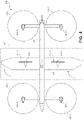
- FIG. 1 illustrates a block diagram of a top-down view of a UAV 100 with a pivot assembly 107 in a lifting position, according to an implementation.
- the UAV 100 includes a frame 104.
- the frame 104 or body of the UAV 100 may be formed of any suitable material, such as graphite, carbon fiber, aluminum, etc., or any combination thereof.
- the frame 104 of the UAV 100 is formed of machined aluminum in a rectangular shape.
- the motor arms 105-1, 105-2 are approximately the same length, are arranged substantially parallel to one another and perpendicular to the frame 104.
- the motor arms 105 may be of different lengths (e.g., the front motor arm 105-1 may be shorter than the rear motor arm 105-2 and/or arranged at different locations on the UAV 100.
- the lifting motor may be mounted so that propeller shaft of the lifting motor that mounts to the propeller 102 is facing downward with respect to the UAV 100.
- the lifting motors may be mounted with the propeller shaft facing upwards with respect to the UAV 100.
- one or more of the lifting motors may be mounted with the propeller shaft facing downward and one or more of the lifting motors may be mounted with the propeller shaft facing upward.
- the lifting motors may be mounted at other angles with respect to the frame of the UAV 100.
- the lifting motors may be any form of motor capable of generating enough rotational speed with the propellers to lift the UAV 100 and any engaged payload, thereby enabling aerial transport of the payload.
- the lifting motors 106 may be encased within a motor housing that has an aerodynamic shape to improve the airflow around the motors while the UAV 100 is moving in a direction that includes a horizontal component.
- the motor housings may be formed of any material, such as carbon fiber, aluminum, graphite, etc.
- the lifting propellers 102 may be any form of propeller (e.g., graphite, carbon fiber) and of a size sufficient to lift the UAV 100 and any payload engaged by the UAV 100.
- the lifting propellers 102 may each be carbon fiber propellers having a dimension or diameter of twenty-nine inches. While the illustration of FIG. 1 shows the lifting propellers 102 all of a same size, in some implementations, one or more of the lifting propellers 102 may be different sizes and/or dimensions. Likewise, while this example includes four lifting propellers, in other implementations, more or fewer propellers may be utilized as lifting propellers.
- the propellers may be positioned at different locations on the UAV 100.
- alternative methods of propulsion may be utilized as "motors" in implementations described herein.
- fans, jets, turbojets, turbo fans, jet engines, internal combustion engines, and the like may be used (either with propellers or other devices) to provide lift for the UAV.
- the antennas 108 may be used to transmit and/or receive wireless communications.
- the antennas 108 may be utilized for Wi-Fi, satellite, near field communication ("NFC"), cellular communication, or any other form of wireless communication.
- Other components, such as cameras, time of flight sensors, distance determining elements, gimbals, etc. may likewise be mounted to the front of the frame 104 of the UAV 100.
- a UAV control system 114 is also mounted to the frame 104.
- the UAV control system 114 is mounted to a top of the frame 104.
- the UAV control system 114, or components thereof, may be mounted or positioned at other locations of the UAV 100.
- the UAV control system 114 controls the operation, routing, navigation, communication, motor controls, and the payload engagement mechanism of the UAV 100.
- the UAV 100 includes one or more power modules (not shown).
- the power modules may be mounted to various locations on the frame 104 of the UAV 100.
- four power modules may be mounted to an underneath side of the frame 104 within a fuselage (not shown).
- the power modules for the UAV 100 may be in the form of battery power, solar power, gas power, super capacitor, fuel cell, alternative power generation source, or a combination thereof.
- the power modules may each be a 6000mAh lithium-ion polymer battery, or polymer lithium ion (Li-poly, Li-Pol, LiPo, LIP, PLI, or Lip) battery.
- the power module(s) are coupled to and provide power for the UAV control system 114, the lifting motors 106, and the thrusting motors 110, the payload engagement mechanism, etc.
- one or more of the power modules may be configured such that it can be autonomously removed and/or replaced with another power module while the UAV is landed or in flight. For example, when the UAV 100 lands at a location, the UAV may engage with a charging member at the location that will recharge the power module.
- the UAV 100 may also include a payload engagement mechanism (not shown).
- the payload engagement mechanism may be configured to engage and disengage a payload (e.g., an item or a container that contains items).
- the payload engagement mechanism may operate as the container, in which it contains item(s).
- the payload engagement mechanism is positioned beneath the frame 104 of the UAV 100.
- the payload engagement mechanism communicates with (via wired or wireless communication) and is controlled by the UAV control system 114.
- the pivot assembly 107 includes four motors 110-1, 110-2, 110-3, 110-4, referred to herein as thrusting motors, and four corresponding propellers 112-1, 112-2, 112-3, 112-4, referred to herein as thrusting propellers.
- the thrusting motors 110 and the thrusting propellers 112 of the pivot assembly 107 may be the same or different than the lifting motors 106 and lifting propellers 102.
- the thrusting propellers 112 may have a smaller dimension than the lifting propellers 102. In other implementations, the thrusting propellers 112 may have a larger dimension than the lifting propellers 102.
- one or more of the thrusting propellers may be single-blade propellers or folding propellers.
- the thrusting propellers 112-1, 112-2 which may not be used when the pivot assembly 107 is in the thrusting position, may be folding propellers that fold in the direction of the wind so that they do not generate drag when the UAV 100 is moving in a horizontal direction.
- the thrusting motors 110 are coupled to a pivot arm 109 that extends from the frame 104 of the UAV 100 and is configured to rotate about an axis with respect to the frame 104 of the UAV 100.
- the pivot assembly 107 may include stops that stop the rotation of the pivot assembly at desired positions (lifting position, thrusting position).
- the pivot assembly 107 includes four thrusting motors 110 and corresponding thrusting propellers 112 positioned about the pivot arm 109.
- fewer or additional thrusting motors and corresponding thrusting propellers may be utilized, provided there are at least two thrusting motors offset with respect to one another about an axis, in this example the pivot arm 109.
- the thrusting motor 110-1 is offset from thrusting motor 110-3 and thrusting motor 110-4.
- thrusting motor 110-2 is offset from thrusting motor 110-4 and thrusting motor 110-3.
- Thrusting motor 110-3 is offset from thrusting motor 110-1 and thrusting motor 110-2.
- Thrusting motor 110-4 is offset from thrusting motor 110-2 and thrusting motor 110-1.
- the pivot assembly will remain in the lifting position, as illustrated in FIG. 1 .
- the thrusting motors 110-3, 110-4 may be disengaged and the thrusting motors 110-1, 110-2 may be engaged and generate a force by rotating the corresponding thrusting propellers 112-1, 112-2. If the combined force generated by thrusting motor 110-3 and thrusting motor 110-4 is greater than the combined force generated by thrusting motor 110-1 and thrusting motor 110-2, the pivot assembly will rotate to the thrusting position, as illustrated in FIG. 2 .
- the pivot assembly 107 may include a dampener, electric brake or other inertial component that requires a differential force between the offset thrusting motors to exceed a threshold before the pivot assembly 107 will rotate from the lifting position, illustrated in FIG. 1 , to the thrusting position, illustrated in FIG. 2 , or from the thrusting position to the lifting position.
- the dampener or other inertial component may be used to position the pivot assembly 107 at other angles with respect to the frame 104 of the UAV 100.
- inertial component refers to any braking mechanism, whether effective through friction (static, dynamic, or viscous) or inertia used to dampen, restrict, stop, resist, or otherwise bias against rotation of pivot assembly 107 about its axis.
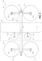
- FIG. 2 depicts a block diagram of a top-down view of the unmanned aerial vehicle 200 with the pivot assembly 207 in a thrusting position, according to an implementation. Except where otherwise noted, reference numerals preceded by the number "2" shown in FIG. 2 indicate components or features that are similar to components or features having reference numerals preceded by the number "1" shown in FIG. 1 .
- one or more of the thrusting motors 210 may be engaged to provide horizontal thrust via the corresponding thrusting propeller 212 to propel the UAV 200 horizontally.
- the thrusting motors 210-3, 210-4 may be engaged to generate thrust from the rotation of the corresponding thrusting propellers 212-3, 212-4.
- the thrusting motors 110-1, 110-2 (not shown in FIG. 2 ) may operate at a rotational speed that is less than thrusting motors 210-3, 210-4, or the thrusting motors 110-1, 110-2 may be disengaged.
- FIG. 3 depicts another block diagram of a top-down view of a UAV 300 that includes a pivot assembly 307 in which the pivot arm 309 is a wing, according to an implementation. Except where otherwise noted, reference numerals preceded by the number "3" shown in FIG. 3 indicate components or features that are similar to components or features having reference numerals preceded by the number "1" shown in FIG. 1 .
- the UAV includes a frame 304, motor arms 305-1, 305-2, lifting motors 306-1, 306-2, 306-3, 306-4, lifting propellers 302-1, 302-2, 302-3, 302-4, antennas 308, UAV control system 314, power modules, payload engagement mechanism, etc.
- the pivot assembly 307 includes four thrusting motors 310-1, 310-2, 310-3, 310-4 and four corresponding thrusting propellers 312-1, 312-2, 312-3, 312-4.
- the thrusting motors 310 are coupled to a pivot arm 309 that extends from the frame 304 of the UAV 300 and is configured to rotate about an axis with respect to the frame 304 of the UAV 300.
- the pivot assembly 307 may include stops that stop the rotation of the pivot assembly at desired positions (lifting position, thrusting position).
- pivot arm 309 includes a wing shape on either side of the frame 304 of the UAV. Thrusting motors and corresponding thrusting propellers are mounted on the top and bottom sides of each wing shape.
- the pivot arm 309 may be a single arm that extends through the frame 304 of the UAV 300 such that both wings of the pivot arm rotate together.
- each wing of the pivot arm may rotate independent of the other wing of the pivot arm. If the wing shapes on either side of the frame 304 rotate independently, each wing will have an offset pair of thrusting motors and corresponding thrusting propellers.
- the wings on either side of the frame 304 are affixed to and essentially part of a single pivot arm that extends through the frame 304, only two offset motors are needed.
- FIG. 3 shows four thrusting motors 310-1, 310-2, 310-3, 310-4 and corresponding thrusting propellers 302-1, 302-2, 302-3, 302-4, in other implementations there may be additional or fewer thrusting motors and corresponding thrusting propellers, provided that there are at least two thrusting motors offset with respect to one another about an axis, in this example the pivot arm 309.
- the thrusting motor 310-1 is offset from thrusting motor 310-3 and thrusting motor 310-4.
- thrusting motor 310-2 is offset from thrusting motor 310-4 and thrusting motor 310-3.
- Thrusting motor 310-3 is offset from thrusting motor 310-1 and thrusting motor 310-2.
- Thrusting motor 310-4 is offset from thrusting motor 310-2 and thrusting motor 310-1.
- the pivot assembly will remain in the lifting position, as illustrated in FIG. 3 .
- the thrusting motors 310-3, 310-4 may be disengaged and the thrusting motors 310-1, 310-2 may be engaged and generate a force by rotating the corresponding thrusting propellers 312-1, 312-2.
- the pivot assembly 307 may include a dampener, electric brake or other inertial component that requires a differential force between the offset thrusting motors to exceed a threshold before the pivot assembly 307 will rotate from the lifting position, illustrated in FIG. 3 , to the thrusting position, illustrated in FIG. 4 , or from the thrusting position to the lifting position.
- the dampener or other inertial component may be used to position the pivot assembly 307 at other angles with respect to the frame 304 of the UAV 300.
- FIG. 4 depicts a block diagram of a top-down view of the unmanned aerial vehicle 400 with the pivot assembly 407 in a thrusting position, according to an implementation. Except where otherwise noted, reference numerals preceded by the number "4" shown in FIG. 4 indicate components or features that are similar to components or features having reference numerals preceded by the number "3" shown in FIG. 3 .
- one or more of the thrusting motors 410 may be engaged to provide horizontal thrust via the corresponding thrusting propeller 412 to propel the UAV 400 horizontally.
- the thrusting motors 410-3, 410-4 may be engaged to generate thrust from the rotation of the corresponding thrusting propellers 412-3, 412-4.
- the thrusting motors 310-1, 310-2 (not shown in FIG. 4 ) may operate at a rotational speed that is less than thrusting motors 410-3, 410-4, or the thrusting motors 310-1, 310-2 may be disengaged.
- the pivot arm 409 is in the shape of a wing, as the UAV 400 moves horizontally, the wing shape of the pivot arm generates a vertical lifting force.
- the wing shape of the pivot arm 409 may be formed of any suitable material such as, but not limited to, carbon fiber, graphite, aluminum, plastic, fiberglass, etc.
- the wing shape of the pivot arm 409 is designed to have an airfoil shape to provide lift to the UAV 400 as the UAV 400 moves horizontally.
- the rotational speed of the lifting motors 406-1, 406-2, 406-3, 406-4 and corresponding lifting propellers 402-1, 402-2, 402-3, 402-4 may be reduced or eliminated because the wing shape of the pivot arm 409 may provide sufficient lift and keep the UAV 400 airborne when thrust in a horizontal direction by the thrusting motors 410 and thrusting propellers 412 is applied.
- the pitch, yaw and roll of the UAV 400 may be controlled using the flaps and/or ailerons alone or in combination with the lifting motors and lifting propellers 402. If the wing shape of the pivot arm 409 does not include flaps and/or ailerons, the lifting motors and lifting propellers 402 may be utilized to control the pitch, yaw, and roll of the UAV 400 during flight.
- FIG. 5 depicts another block diagram of a top-down view of a UAV 500 that includes a pivot assembly 507 in which the pivot arm 509 is a wing, according to an implementation not according to the invention and provided for illustration purposes only. Except where otherwise noted, reference numerals preceded by the number "5" shown in FIG. 5 indicate components or features that are similar to components or features having reference numerals preceded by the number "3" shown in FIG. 3 .
- the UAV includes a frame 504, motor arms 505-1, 505-2, lifting motors 506-1, 506-2, 506-3, 506-4, lifting propellers 502-1, 502-2, 502-3, 502-4, antennas 508, UAV control system 514, power modules, payload engagement mechanism, etc.
- the pivot assembly 507 includes two thrusting motors 510-3, 510-4 and two corresponding thrusting propellers 512-3, 512-4.
- the thrusting motors 510-3, 510-4 are configured to rotate the thrusting propellers 512-3, 512-4 in either direction.
- the thrusting motors 510-3, 510-4 rotate in a first rotational direction (e.g., clockwise)
- the thrusting propellers 512-3, 512-4 generate a directional force in a first direction.
- the thrusting propellers 512-3, 512-4 When the thrusting motors 510-3, 510-4 rotate in a second rotational direction (e.g., counter-clockwise), the thrusting propellers 512-3, 512-4 generate a direction force in a second, opposite direction.
- the thrusting motors 510 are coupled to a pivot arm 509 that extends from the frame 504 of the UAV 500 and is configured to rotate about an axis with respect to the frame 504 of the UAV 500.
- the pivot assembly 507 may include stops that stop the rotation of the pivot assembly at desired positions (lifting position, thrusting position).
- pivot arm 509 includes a wing shape on either side of the frame 504 of the UAV.
- the thrusting motors and corresponding thrusting propellers are mounted on the top of each wing shape.
- the thrusting motors and corresponding thrusting propellers may be mounted on the bottom of each wing shape.
- the thrusting motors 510-3, 510-4 rotate in a first rotational direction the force generated by the corresponding thrusting propellers 512-3, 512-4 will generate a downward direction force that will cause the pivot assembly to remain in the lifting position, as illustrated in FIG. 5 .
- the pivot assembly 507 may include a dampener, electric brake or other inertial component that requires a force generated by the thrusting motors to exceed a threshold before the pivot assembly 507 will rotate from the lifting position, illustrated in FIG. 5 , to the thrusting position, illustrated in FIG. 4 , or from the thrusting position to the lifting position.
- the dampener or other inertial component may be used to position the pivot assembly 507 at other angles with respect to the frame 504 of the UAV 500.
- FIG. 6 depicts a block diagram of a side-view of a portion of a pivot assembly 607 in a lifting position, according to an implementation.
- the pivot assembly 607 extends from and rotates about a frame 604 of a UAV.
- the pivot assembly includes an axis 624 about which the pivot assembly 607 rotates.
- the pivot assembly may rotate on bearings, bushings, without the need of any additional motors, gears or other drive mechanisms other than the thrusting motors 610-1, 610-3 and corresponding thrusting propellers 612-1, 612-3 discussed above.
- the pivot arm 609 has an airfoil shape of a wing, similar to the pivot arms discussed above with respect to FIGs. 3 - 5 .
- the thrusting motors 610-1, 610-3 are coupled to motor arms 614-1, 614-3 that are coupled to the pivot arm 609 and the thrusting motors 610 are in opposite directions from the pivot arm 609.
- the pivot assembly also includes mechanical stops 626-1, 626-1 positioned at desired locations that will inhibit rotation of the pivot arm between the lifting position ( FIG. 6 ) and the thrusting position ( FIG. 7 ).
- a stop bar 628 may extend from the axis of the pivot arm and be configured to engage the mechanical stops 626-1, 626-2 to inhibit the rotation of the pivot assembly.
- the thrusting motors 610 and thrusting propellers 612 may generate force to aid in the vertical lift of the UAV.
- the pivot assembly 607 will rotate about the axis 624 until the stop bar engages with the mechanical stop 626-2 and the pivot assembly is in the thrusting position, as illustrated in FIG. 7 .
- the pivot assembly 607 may include a dampener, electric brake, clutch or other inertial component that requires a differential force between the thrusting motor 610-1 and the thrusting motor 610-3 to exceed a threshold before the pivot assembly 607 will rotate from the lifting position ( FIG. 6 ) to the thrusting position ( FIG. 7 ), or from the thrusting position to the lifting position.
- the dampener or other inertial component may be used to position the pivot assembly 607 at other angles with respect to the frame 604 of the UAV.
- the dampener, electric brake, clutch, or other inertial component may be selectively engaged to stop and/or prohibit rotation of the pivot assembly 607 at any angle between the two mechanical stops.
- FIG. 7 depicts a block diagram of a side-view of a portion of a pivot assembly 707 in a thrusting position, according to an implementation. Except where otherwise noted, reference numerals preceded by the number "8" shown in FIG. 7 indicate components or features that are similar to components or features having reference numerals preceded by the number "6" shown in FIG. 6 .
- the pivot assembly 707 has rotated from the lifting position ( FIG. 6 ) to the thrusting position ( FIG. 7 ) because the force (F2) generated by the thrusting motor 710-3 and corresponding thrusting propeller 712-3 exceeds the force (F1) generated by the thrusting motor 710-1 and corresponding thrusting propeller 712-1.
- the stop bar 728 has rotated about the axis 724 from the mechanical stop 726-1 to the mechanical stop 726-2 and will remain engaged with the mechanical stop 726-2 as long as the force (F2) from the thrusting motor 710-3 and corresponding thrusting propeller 712-3 exceeds the force (F1) generated by the thrusting motor 710-1 and corresponding thrusting propeller 712-1 because the mechanical stop 726-2 is inhibiting rotation of the pivot arm in the second direction.
- FIG. 8 is a block diagram illustrating an example UAV control system 814 of a UAV.
- the block diagram may be illustrative of one or more aspects of the UAV control system 814 that may be used to implement the various systems and methods discussed herein and/or to control operation of a UAV.
- the UAV control system 814 includes one or more processors 802, coupled to a memory, e.g., a non-transitory computer readable storage medium 820, via an input/output (I/O) interface 810.
- the UAV control system 814 may also include electronic speed controls 804 (ESCs), power supply modules 806 and/or a navigation system 808.
- the UAV control system 814 further includes a payload engagement controller 812, a network interface 816, and one or more input/output devices 818.
- the UAV control system 814 may be a uniprocessor system including one processor 802, or a multiprocessor system including several processors 802 (e.g., two, four, eight, or another suitable number).
- the processor(s) 802 may be any suitable processor capable of executing instructions.
- the processor(s) 802 may be general-purpose or embedded processors implementing any of a variety of instruction set architectures (ISAs), such as the x86, PowerPC, SPARC, or MIPS ISAs, or any other suitable ISA.
- ISAs instruction set architectures
- each processor(s) 802 may commonly, but not necessarily, implement the same ISA.
- the non-transitory computer readable storage medium 820 may be configured to store executable instructions, data, flight paths, flight control parameters, pivot assembly, and/or data items accessible by the processor(s) 802.
- the non-transitory computer readable storage medium 820 may be implemented using any suitable memory technology, such as static random access memory (SRAM), synchronous dynamic RAM (SDRAM), nonvolatile/Flash-type memory, or any other type of memory.
- SRAM static random access memory
- SDRAM synchronous dynamic RAM
- Flash-type memory nonvolatile/Flash-type memory
- program instructions and data implementing desired functions, such as those described herein, are shown stored within the non-transitory computer readable storage medium 820 as program instructions 822, data storage 824 and flight controls 826, respectively.
- program instructions, data, and/or flight controls may be received, sent, or stored upon different types of computer-accessible media, such as non-transitory media, or on similar media separate from the non-transitory computer readable storage medium 820 or the UAV control system 814.
- a non-transitory, computer readable storage medium may include storage media or memory media such as magnetic or optical media, e.g., disk or CD/DVD-ROM, coupled to the UAV control system 814 via the I/O interface 810.
- Program instructions and data stored via a non-transitory computer readable medium may be transmitted by transmission media or signals such as electrical, electromagnetic, or digital signals, which may be conveyed via a communication medium such as a network and/or a wireless link, such as may be implemented via the network interface 816.
- transmission media or signals such as electrical, electromagnetic, or digital signals, which may be conveyed via a communication medium such as a network and/or a wireless link, such as may be implemented via the network interface 816.
- the I/O interface 810 may be configured to coordinate I/O traffic between the processor(s) 802, the non-transitory computer readable storage medium 820, and any peripheral devices, the network interface or other peripheral interfaces, such as input/output devices 818.
- the I/O interface 810 may perform any necessary protocol, timing or other data transformations to convert data signals from one component (e.g., non-transitory computer readable storage medium 820) into a format suitable for use by another component (e.g., processor(s) 802).
- the I/O interface 810 may include support for devices attached through various types of peripheral buses, such as a variant of the Peripheral Component Interconnect (PCI) bus standard or the Universal Serial Bus (USB) standard, for example.
- PCI Peripheral Component Interconnect
- USB Universal Serial Bus
- the function of the I/O interface 810 may be split into two or more separate components, such as a north bridge and a south bridge, for example.
- some or all of the functionality of the I/O interface 810 such as an interface to the non-transitory computer readable storage medium 820, may be incorporated directly into the processor(s) 802.
- the ESCs 804 communicate with the navigation system 808 and adjust the rotational speed of each lifting motor and/or the thrusting motor to stabilize the UAV, guide the UAV along a determined flight path and/or cause rotation of the pivot assembly from a lifting position to a thrusting position or from a thrusting position to a lifting position.
- the navigation system 808 may include a global positioning system (GPS), indoor positioning system (IPS), or other similar system and/or sensors that can be used to navigate the UAV to and/or from a location.
- GPS global positioning system
- IPS indoor positioning system
- the payload engagement controller 812 communicates with the actuator(s) or motor(s) (e.g., a servo motor) used to engage and/or disengage items.
- the network interface 816 may be configured to allow data to be exchanged between the UAV control system 814, other devices attached to a network, such as other computer systems (e.g., remote computing resources), and/or with UAV control systems of other UAVs.
- the network interface 816 may enable wireless communication between the UAV and a UAV control system that is implemented on one or more remote computing resources.
- an antenna of an UAV or other communication components may be utilized.
- the network interface 816 may enable wireless communication between numerous UAVs.
- the network interface 816 may support communication via wireless general data networks, such as a Wi-Fi network.
- the network interface 816 may support communication via telecommunications networks, such as cellular communication networks, satellite networks, and the like.
- Input/output devices 818 may, in some implementations, include one or more displays, imaging devices, thermal sensors, infrared sensors, time of flight sensors, accelerometers, pressure sensors, weather sensors, etc. Multiple input/output devices 818 may be present and controlled by the UAV control system 814. One or more of these sensors may be utilized to assist in landing as well as to avoid obstacles during flight.
- the memory may include program instructions 822, which may be configured to implement the example routines and/or sub-routines described herein.
- the data storage 824 may include various data stores for maintaining data items that may be provided for determining flight paths, landing, identifying locations for disengaging items, etc.
- the parameter values and other data illustrated herein as being included in one or more data stores may be combined with other information not described or may be partitioned differently into more, fewer, or different data structures.
- data stores may be physically located in one memory or may be distributed among two or more memories.
- the UAV control system 814 is merely illustrative and is not intended to limit the scope of the present disclosure.
- the computing system and devices may include any combination of hardware or software that can perform the indicated functions.
- the UAV control system 814 may also be connected to other devices that are not illustrated, or instead may operate as a stand-alone system.
- the functionality provided by the illustrated components may, in some implementations, be combined in fewer components or distributed in additional components.
- the functionality of some of the illustrated components may not be provided and/or other additional functionality may be available.
- instructions stored on a computer-accessible medium separate from the UAV control system 814 may be transmitted to the UAV control system 814 via transmission media or signals such as electrical, electromagnetic, or digital signals, conveyed via a communication medium such as a wireless link.
- Various implementations may further include receiving, sending or storing instructions and/or data implemented in accordance with the foregoing description upon a computer-accessible medium. Accordingly, the techniques described herein may be practiced with other UAV control system configurations.
- An embodiment disclosed herein includes an unmanned aerial vehicle (UAV) including a frame, two motor arms mounted to the frame, a plurality of lifting motors and corresponding lifting propellers mounted to respective ends of the motor arms.
- the lifting motors are oriented to provide a vertical lift to the UAV when the lifting propellers are rotated by the lifting motors and a pivot assembly coupled to the frame of the UAV and configured to rotate from a lifting position to a thrusting position.
- the pivot assembly includes a pivot arm extending from the frame of the UAV and configured to rotate with respect to the frame of the UAV, a first pivot motor coupled to the pivot arm, and a second pivot motor coupled to the pivot arm and offset with respect to the first motor.
- the pivot assembly is configured to rotate to the lifting position when a first force generated by the first pivot motor is greater than a second force generated by the second pivot motor.
- the pivot assembly is configured to rotate to the thrusting position when the second force generated by the second pivot motor is greater than the first force generated by the first pivot motor.
- the first force and the second force may provide a lifting force for the UAV when the pivot assembly is in the lifting position.
- the first force and the second force may provide a thrusting force when the pivot assembly is in the thrusting position.
- the first and the second pivot motors may be approximately perpendicular to the frame of the UAV when the pivot assembly is in the thrusting position.
- at least a portion of the pivot arm may be formed in a shape of a wing.
- a pivot assembly including one or more of a pivot arm configured to rotate about an axis, a first motor coupled to the pivot arm and disposed at a first position with respect to the pivot arm, a second motor coupled to the pivot arm and disposed at a second position with respect to the pivot arm, wherein the first motor and the second motor are offset with respect to one another, a first mechanical stop that inhibits a rotation of the pivot arm in a first direction about the axis, and a second mechanical stop that inhibits the rotation of the pivot arm in a second direction about the axis.
- a first force generated by the first motor exceeds a second force generated by the second motor
- rotation of the pivot arm in the first direction may be inhibited by the first mechanical stop.
- the second force generated by the second motor exceeds the first force generated by the first motor
- rotation of the pivot arm in the second direction may be inhibited by the second mechanical stop.
- the first force and the second force may comprise a lifting force when rotation of the pivot arm is inhibited by the first mechanical stop.
- the first force and the second force may comprise a thrusting force when rotation of the pivot arm is inhibited by the second mechanical stop.
- the pivot assembly may be coupled to a vehicle, may provide a lifting force for the vehicle when the pivot arm is inhibited by the first mechanical stop, and/or may provide a thrusting force for the vehicle when the pivot arm is inhibited by the second mechanical stop.
- the vehicle may comprise at least one of an aerial vehicle, an unmanned aerial vehicle, a ground based vehicle, an unmanned ground based vehicle, a water based vehicle, an unmanned water based vehicle, a spacecraft, and/or an unmanned spacecraft.
- a vehicle having one or more of a frame, a power module coupled to the frame, and a pivot assembly coupled to the frame.
- the pivot assembly may comprise one or more of a pivot arm configured to rotate about an axis with respect to the frame, a first motor coupled to the pivot arm and powered by the power module, and a second motor coupled to the pivot arm and offset with respect to the first motor, the second motor powered by the power module.
- the first motor may be configured to rotate with the pivot arm and the second motor may be configured to rotate with the pivot arm.
- the pivot assembly may be in a lifting position when a first force generated by the first motor is greater than a second force generated by the second motor and the pivot assembly may be in a thrusting position when the second force generated by the second motor is greater than the first force generated by the first motor.
- the pivot assembly may further include an inertial component that prohibits rotation of the pivot assembly if the first force is less than a threshold.
- the inertial component may comprise one or more of a brake, a clutch, or a dampener.
- at least a portion of the pivot arm may be formed in a shape of a wing.
- the second motor may be disengaged when the pivot assembly is in the lifting position.
- the first motor may provide vertical lift to the vehicle when the pivot assembly is in the lifting position.
- the first motor may be disengaged when the pivot assembly is in the thrusting position.
- the second motor may provide thrust to the vehicle when the pivot assembly is in the thrusting position.
- the pivot assembly may rotate between the lifting position and the thrusting position as a result of a differential force produced by the first motor and the second motor.
Landscapes
- Engineering & Computer Science (AREA)
- Combustion & Propulsion (AREA)
- Chemical & Material Sciences (AREA)
- Aviation & Aerospace Engineering (AREA)
- Mechanical Engineering (AREA)
- Remote Sensing (AREA)
- Physics & Mathematics (AREA)
- Ocean & Marine Engineering (AREA)
- Fluid Mechanics (AREA)
- Transportation (AREA)
- General Physics & Mathematics (AREA)
- Astronomy & Astrophysics (AREA)
- Toys (AREA)
- Connection Of Motors, Electrical Generators, Mechanical Devices, And The Like (AREA)
Claims (9)
- Unbemanntes Luftfahrzeug, UAV, (100, 200, 300, 400), das Folgendes umfasst:einen Rahmen (104, 204, 304, 404, 604); zwei Motorarme (105-1, 105-2), montiert am Rahmen;mehrere Hubmotoren (106) und entsprechende Hubpropeller (102), montiert an entsprechenden Enden der Motorarme, wobei die Hubmotoren ausgerichtet sind, um einen vertikalen Hub für das UAV bereitzustellen, wenn die Hubpropeller durch die Hubmotoren gedreht werden;eine Schwenkanordnung (107, 607), gekoppelt mit dem Rahmen, wobei die Schwenkanordnung Folgendes umfasst:einen Schwenkarm (609), ausgelegt zum Drehen um eine Achse (624);einen ersten Motor (610-1), gekoppelt mit dem Schwenkarm und angeordnet an einer ersten Position bezüglich des Schwenkarms;einen zweiten Motor (610-3), gekoppelt mit dem Schwenkarm und angeordnet an einer zweiten Position bezüglich des Schwenkarms, wobei der erste Motor und der zweite Motor bezüglich einander versetzt sind;einen ersten mechanischen Anschlag (626-1), der eine Drehung des Schwenkarms in eine erste Richtung um die Achse unterbindet;einen zweiten mechanischen Anschlag (626-2), der die Drehung des Schwenkarms in eine zweite Richtung um die Achse unterbindet;wobei:wenn eine durch den ersten Motor erzeugte erste Kraft (F1) eine durch den zweiten Motor erzeugte zweite Kraft (F2) überschreitet, Drehung des Schwenkarms in die erste Richtung durch den ersten mechanischen Anschlag verhindert wird; undwenn eine durch den zweiten Motor erzeugte zweite Kraft die durch den ersten Motor erzeugte erste Kraft überschreitet, Drehung des Schwenkarms in die zweite Richtung durch den zweiten mechanischen Anschlag verhindert wird.
- Fahrzeug nach Anspruch 1, wobei die erste Kraft und die zweite Kraft eine Hubkraft sind, wenn Drehung des Schwenkarms durch den ersten mechanischen Anschlag verhindert wird.
- Fahrzeug nach einem der Ansprüche 1 oder 2, wobei die erste Kraft und die zweite Kraft eine Schubkraft sind, wenn Drehung des Schwenkarms durch den zweiten mechanischen Anschlag verhindert wird.
- Fahrzeug nach einem der vorhergehenden Ansprüche, das ferner Folgendes umfasst: ein mit dem Rahmen gekoppeltes Leistungsmodul.
- Fahrzeug nach einem der vorhergehenden Ansprüche, wobei die Schwenkanordnung ferner eine Trägheitskomponente umfasst, die Drehung der Schwenkanordnung verhindert, wenn die erste Kraft kleiner als eine Schwelle ist.
- Fahrzeug nach Anspruch 5, wobei die Trägheitskomponente eines oder mehrere aus einer Bremse, einer Kupplung oder einem Dämpfer umfasst.
- Fahrzeug nach einem der vorhergehenden Ansprüche, wobei zumindest ein Teil des Schwenkarms in einer Form eines Flügels gebildet ist.
- Fahrzeug nach einem der vorhergehenden Ansprüche, wobei der zweite Motor deaktiviert ist, wenn die Schwenkanordnung die Hubkraft bereitstellt.
- Fahrzeug nach einem der vorhergehenden Ansprüche, wobei der erste Motor deaktiviert ist, wenn die Schwenkanordnung die Schubkraft bereitstellt.
Applications Claiming Priority (2)
| Application Number | Priority Date | Filing Date | Title |
|---|---|---|---|
| US14/626,357 US9561849B2 (en) | 2015-02-19 | 2015-02-19 | Vehicle configuration with motors that rotate between a lifting position and a thrusting position |
| PCT/US2016/018548 WO2016134190A1 (en) | 2015-02-19 | 2016-02-18 | Vehicle configuration with motors that rotate between a lifting position and a thrusting position |
Publications (2)
| Publication Number | Publication Date |
|---|---|
| EP3259184A1 EP3259184A1 (de) | 2017-12-27 |
| EP3259184B1 true EP3259184B1 (de) | 2022-04-06 |
Family
ID=55453310
Family Applications (1)
| Application Number | Title | Priority Date | Filing Date |
|---|---|---|---|
| EP16708045.6A Active EP3259184B1 (de) | 2015-02-19 | 2016-02-18 | Unbemanntes luftfahrzeug |
Country Status (6)
| Country | Link |
|---|---|
| US (3) | US9561849B2 (de) |
| EP (1) | EP3259184B1 (de) |
| JP (2) | JP6450465B2 (de) |
| CN (1) | CN107406141B (de) |
| CA (1) | CA2976781C (de) |
| WO (1) | WO2016134190A1 (de) |
Families Citing this family (63)
| Publication number | Priority date | Publication date | Assignee | Title |
|---|---|---|---|---|
| US9384668B2 (en) | 2012-05-09 | 2016-07-05 | Singularity University | Transportation using network of unmanned aerial vehicles |
| IL234443B (en) * | 2014-09-02 | 2019-03-31 | Regev Amit | Swing-wing multi-bladed rifle |
| US11254430B2 (en) | 2014-09-02 | 2022-02-22 | Amit REGEV | Tilt winged multi rotor |
| US9908619B1 (en) * | 2014-09-25 | 2018-03-06 | Amazon Technologies, Inc. | Ballast control mechanisms for aerial vehicles |
| FR3032687B1 (fr) * | 2015-02-16 | 2018-10-12 | Hutchinson | Aerodyne vtol a soufflante(s) axiale(s) porteuse(s) |
| US9938005B2 (en) * | 2015-07-17 | 2018-04-10 | Teal Drones, Inc. | Thrust vectoring on a rotor-based remote vehicle |
| CN108290633A (zh) * | 2015-11-10 | 2018-07-17 | 马特耐特公司 | 使用无人航空载具进行运输的方法和系统 |
| WO2017096478A1 (en) | 2015-12-11 | 2017-06-15 | Coriolis Games Corporation | Hybrid multicopter and fixed wing aerial vehicle |
| US10232931B2 (en) * | 2015-12-18 | 2019-03-19 | Amazon Technologies, Inc. | Selecting propellers for performance and noise shaping |
| US9745050B2 (en) | 2015-12-18 | 2017-08-29 | Amazon Technologies, Inc. | Selecting propellers for performance and noise shaping |
| US10377483B2 (en) * | 2016-03-01 | 2019-08-13 | Amazon Technologies, Inc. | Six degree of freedom aerial vehicle with offset propulsion mechanisms |
| US10618649B2 (en) * | 2016-03-01 | 2020-04-14 | Amazon Technologies, Inc. | Six degree of freedom aerial vehicle |
| US11027837B2 (en) * | 2016-07-01 | 2021-06-08 | Textron Innovations Inc. | Aircraft having thrust to weight dependent transitions |
| US10315761B2 (en) * | 2016-07-01 | 2019-06-11 | Bell Helicopter Textron Inc. | Aircraft propulsion assembly |
| CN109562825B (zh) * | 2016-08-26 | 2022-08-05 | 小鹰公司 | 具有宽跨度旋翼配置的多旋翼飞行器 |
| CN107933894A (zh) * | 2016-10-13 | 2018-04-20 | 赵蓝婷 | 一种提高飞行器飞行安全的装置及其方法 |
| KR102414458B1 (ko) | 2016-12-08 | 2022-06-30 | 씨알 플라이트 엘.엘.씨. | 고전류 및 rpm 가능한 슬립 링 어셈블리 |
| JP6454318B2 (ja) * | 2016-12-28 | 2019-01-16 | ヤマハ発動機株式会社 | マルチコプタ |
| IL256941A (en) * | 2018-01-15 | 2018-03-29 | Colugo Systems Ltd | A free wing multirotor with vertical and horizontal rotors |
| US10526079B1 (en) | 2017-07-13 | 2020-01-07 | Kitty Hawk Corporation | Multicopter with wide span rotor configuration and protective fuselage |
| JP6578477B2 (ja) * | 2017-10-10 | 2019-09-25 | 株式会社エアロネクスト | 回転翼機 |
| US10836481B2 (en) * | 2017-11-09 | 2020-11-17 | Bell Helicopter Textron Inc. | Biplane tiltrotor aircraft |
| CN108107902B (zh) * | 2017-12-20 | 2021-06-18 | 成都纵横自动化技术股份有限公司 | 横航向姿态控制方法及相关装置 |
| US11267555B2 (en) * | 2018-01-08 | 2022-03-08 | GEOSAT Aerospace & Technology | Methods and unmanned aerial vehicles for longer duration flights |
| US11117657B2 (en) | 2018-01-19 | 2021-09-14 | Aerhart, LLC | Aeronautical apparatus |
| WO2019147587A1 (en) | 2018-01-23 | 2019-08-01 | Cr Flight, Llc | Counter-rotating electric motor system for high efficiency operation of a hybrid or electric vehicle |
| WO2019147588A1 (en) | 2018-01-23 | 2019-08-01 | Cr Flight, Llc | Hybrid vehicle counter-rotating motor adapted driveline and retro-fit system |
| JP7085892B2 (ja) * | 2018-05-14 | 2022-06-17 | 川崎重工業株式会社 | 飛行体及び飛行体の制御方法 |
| DE102018210740A1 (de) * | 2018-06-29 | 2020-01-02 | Robert Bosch Gmbh | Flugvorrichtung |
| US12157564B2 (en) | 2018-07-04 | 2024-12-03 | Aerhart, LLC | Aeronautical apparatus |
| US11964756B2 (en) | 2018-07-04 | 2024-04-23 | Aerhart, LLC | Aeronautical apparatus |
| US11319066B2 (en) * | 2018-07-10 | 2022-05-03 | Textron Innovations Inc. | Flying wing aircraft having a compact storage configuration |
| EP3604129B1 (de) * | 2018-08-03 | 2021-04-21 | Fuvex Civil, SL | Unbemanntes luftfahrzeug mit unterschiedlichen flugmodi |
| JP7207699B2 (ja) * | 2018-10-10 | 2023-01-18 | ルーチェサーチ株式会社 | 無人飛行体 |
| JP7221514B2 (ja) * | 2018-10-10 | 2023-02-14 | ルーチェサーチ株式会社 | 無人飛行体 |
| IL263301B2 (en) | 2018-11-25 | 2023-09-01 | Israel Aerospace Ind Ltd | Aircraft and the method of operation of aircraft |
| US11964770B2 (en) | 2018-12-27 | 2024-04-23 | Honda Motor Co., Ltd. | Flying body with a control section having a plurality of operational modes |
| WO2020137104A1 (ja) | 2018-12-27 | 2020-07-02 | 本田技研工業株式会社 | 飛行体 |
| FR3093994B1 (fr) * | 2019-03-18 | 2021-06-11 | Airbus Helicopters | Procédé et dispositif pour déplacer un centre de gravité d’un aéronef |
| WO2020191489A1 (en) * | 2019-03-28 | 2020-10-01 | 10270725 Canada Corp. | Multicopter helicopter and method of manufacture thereof |
| CN113677187A (zh) * | 2019-03-28 | 2021-11-19 | 渥美不动产有限公司 | 具备圆柱形旋转体的作业装置 |
| KR102328559B1 (ko) * | 2019-09-17 | 2021-11-18 | 주식회사 위즈윙 | 가변형 무인비행체 및 이를 위한 동작 방법 |
| JP7342250B2 (ja) * | 2019-10-09 | 2023-09-11 | キティー・ホーク・コーポレーション | 異なる飛行モードのためのハイブリット電力システム |
| JPWO2021074986A1 (de) * | 2019-10-16 | 2021-04-22 | ||
| JP7347154B2 (ja) * | 2019-11-21 | 2023-09-20 | 株式会社デンソー | 電動航空機用電駆動システムの制御装置、電動航空機およびコンピュータプログラム |
| US11851178B2 (en) * | 2020-02-14 | 2023-12-26 | The Aerospace Corporation | Long range endurance aero platform system |
| CN113636074A (zh) * | 2020-05-11 | 2021-11-12 | 乌鲁木齐市达坂城海为支油风电有限公司 | 一种智能调节机身平衡的无人机飞行器 |
| CN112340005A (zh) * | 2020-11-13 | 2021-02-09 | 辽宁科技大学 | 一种基于快递接收柜的多旋翼快递无人机 |
| RU2759061C1 (ru) * | 2021-05-24 | 2021-11-09 | Закрытое акционерное общество "Инновационный центр "Бирюч" (ЗАО "ИЦ "Бирюч") | Летательный аппарат вертикального взлета и посадки с дополнительными грузовыми модулями и выдвигаемыми воздушными винтами |
| US11541999B2 (en) * | 2021-06-01 | 2023-01-03 | Hoversurf, Inc. | Methods of vertical take-off/landing and horizontal straight flight of aircraft and aircraft for implementation |
| EP4105123B1 (de) * | 2021-06-18 | 2023-08-30 | Leonardo S.p.A. | Umwandelbares schwebefähiges fluggerät und zugehöriges steuerungsverfahren |
| CN113232851B (zh) * | 2021-06-28 | 2022-09-27 | 宁波阿瑞斯自动化技术有限公司 | 一种多轴共轴双桨多旋翼无人机 |
| DE202022100818U1 (de) | 2022-02-14 | 2022-05-03 | Georgiy Volodymyrovych Beylin | Multikopter |
| US20250214722A1 (en) * | 2022-03-31 | 2025-07-03 | Austin Aeronautics Pty Ltd | Unmanned fixed wing vertical take-off and landing aircraft |
| CN218258678U (zh) * | 2022-07-25 | 2023-01-10 | 深圳市道通智能航空技术股份有限公司 | 一种机臂及无人机 |
| EP4568895A1 (de) * | 2022-08-09 | 2025-06-18 | Pete Bitar | Kompakte und leichte drohnenabgabevorrichtung mit lichtbogendrohnensystem mit luftkanalluftantriebssystem und relativ geringer flugverfolgbarkeit |
| CN115123474B (zh) * | 2022-08-30 | 2022-12-30 | 山东博远视讯信息技术有限公司 | 一种用于停驻无人机的安全浮标平台 |
| CN115320838A (zh) * | 2022-10-13 | 2022-11-11 | 中国地震应急搜救中心 | 一种地震救援高空监测无人机 |
| KR102765122B1 (ko) * | 2022-11-01 | 2025-02-07 | 주식회사 니나노컴퍼니 | 비행 모드 전환이 가능한 드론 |
| EP4488172A4 (de) * | 2023-03-03 | 2025-06-18 | Sichuan Aerofugia Technology Development Co., Ltd. | Senkrecht startendes und landendes flugzeug und steuerungsverfahren für senkrecht startendes und landendes flugzeug |
| CN116080900B (zh) * | 2023-03-03 | 2024-06-18 | 成都沃飞天驭科技有限公司 | 一种垂直起降飞行器和垂直起降飞行器的控制方法 |
| EP4667357A1 (de) * | 2023-05-08 | 2025-12-24 | Sichuan Aerofugia Technology Development Co., Ltd. | Senkrecht startendes und landendes flugzeug und steuerungsverfahren für senkrecht startendes und landendes flugzeug |
| CN117963141B (zh) * | 2024-03-29 | 2024-06-07 | 无锡葫芦科技有限公司 | 一种播种无人机 |
Citations (1)
| Publication number | Priority date | Publication date | Assignee | Title |
|---|---|---|---|---|
| WO2009059173A1 (en) * | 2007-11-02 | 2009-05-07 | Raytheon Company | Methods and apparatus for transforming unmanned aerial vehicle |
Family Cites Families (14)
| Publication number | Priority date | Publication date | Assignee | Title |
|---|---|---|---|---|
| US3039719A (en) * | 1956-11-16 | 1962-06-19 | Haviland H Platt | Vertical take-off airplane |
| US3231221A (en) * | 1964-03-10 | 1966-01-25 | Haviland H Platt | Vertical take-off airplanes |
| US3350035A (en) * | 1964-08-19 | 1967-10-31 | Ernest W Schlieben | Vtol with cylindrical wing |
| US20100032947A1 (en) * | 2008-03-06 | 2010-02-11 | Bevirt Joeben | Apparatus for generating power using jet stream wind power |
| US20110042508A1 (en) | 2009-08-24 | 2011-02-24 | Bevirt Joeben | Controlled take-off and flight system using thrust differentials |
| US8733690B2 (en) * | 2009-08-24 | 2014-05-27 | Joby Aviation, Inc. | Lightweight vertical take-off and landing aircraft and flight control paradigm using thrust differentials |
| WO2012141736A1 (en) * | 2010-10-06 | 2012-10-18 | Shaw Donlad Orval | Aircraft with wings and movable propellers |
| CN102363445B (zh) * | 2011-06-21 | 2014-07-30 | 杨朝习 | 倾转动力式垂直起降陆空两用飞行器 |
| DE102012104783B4 (de) | 2012-06-01 | 2019-12-24 | Quantum-Systems Gmbh | Fluggerät, bevorzugt UAV, Drohne und/oder UAS |
| CN203681869U (zh) * | 2013-12-24 | 2014-07-02 | 西安交通大学 | 适用于垂直起降飞行器的动力系统结构 |
| US9550567B1 (en) * | 2014-10-27 | 2017-01-24 | Amazon Technologies, Inc. | In-flight reconfigurable hybrid unmanned aerial vehicle |
| US20200010182A1 (en) * | 2015-11-07 | 2020-01-09 | Joseph Raymond RENTERIA | Pivoting wing system for vtol aircraft |
| US10252796B2 (en) * | 2016-08-09 | 2019-04-09 | Kitty Hawk Corporation | Rotor-blown wing with passively tilting fuselage |
| KR102141460B1 (ko) * | 2018-09-07 | 2020-08-05 | 한국과학기술연구원 | 부력기구를 구비한 무인 비행체 및 무인 비행체의 자세제어방법 |
-
2015
- 2015-02-19 US US14/626,357 patent/US9561849B2/en active Active
-
2016
- 2016-02-18 CA CA2976781A patent/CA2976781C/en active Active
- 2016-02-18 CN CN201680010950.XA patent/CN107406141B/zh active Active
- 2016-02-18 EP EP16708045.6A patent/EP3259184B1/de active Active
- 2016-02-18 JP JP2017541620A patent/JP6450465B2/ja active Active
- 2016-02-18 WO PCT/US2016/018548 patent/WO2016134190A1/en not_active Ceased
- 2016-12-16 US US15/381,743 patent/US10435146B2/en active Active
-
2018
- 2018-12-07 JP JP2018229673A patent/JP6570093B2/ja active Active
-
2019
- 2019-08-26 US US16/550,795 patent/US11319063B2/en active Active
Patent Citations (1)
| Publication number | Priority date | Publication date | Assignee | Title |
|---|---|---|---|---|
| WO2009059173A1 (en) * | 2007-11-02 | 2009-05-07 | Raytheon Company | Methods and apparatus for transforming unmanned aerial vehicle |
Also Published As
| Publication number | Publication date |
|---|---|
| EP3259184A1 (de) | 2017-12-27 |
| CA2976781C (en) | 2020-03-10 |
| CA2976781A1 (en) | 2016-08-25 |
| US20200010184A1 (en) | 2020-01-09 |
| US11319063B2 (en) | 2022-05-03 |
| US9561849B2 (en) | 2017-02-07 |
| JP6450465B2 (ja) | 2019-01-09 |
| JP2018508407A (ja) | 2018-03-29 |
| US20170101175A1 (en) | 2017-04-13 |
| JP2019069765A (ja) | 2019-05-09 |
| JP6570093B2 (ja) | 2019-09-04 |
| US10435146B2 (en) | 2019-10-08 |
| CN107406141B (zh) | 2020-10-30 |
| CN107406141A (zh) | 2017-11-28 |
| WO2016134190A1 (en) | 2016-08-25 |
| US20160244157A1 (en) | 2016-08-25 |
Similar Documents
| Publication | Publication Date | Title |
|---|---|---|
| CA2976781C (en) | Vehicle configuration with motors that rotate between a lifting position and a thrusting position | |
| US10293937B2 (en) | Unmanned aerial vehicle protective frame configuration | |
| US20230303248A1 (en) | Hexagonal ring wing aerial vehicle | |
| CA2978176C (en) | Unmanned aerial vehicle with external frame carrying thrust propellers and internal frame carrying lift propellers | |
| US10647419B1 (en) | Unmanned aerial vehicle configuration | |
| US9764829B1 (en) | Multirotor aircraft with enhanced yaw control | |
| CA2966654C (en) | Unmanned aerial vehicle configuration for extended flight | |
| US20170283048A1 (en) | Convertable lifting propeller for unmanned aerial vehicle | |
| EP3844583B1 (de) | Verfahren zur steuerung eines flugzeugs mit sechs freiheitsgraden mit reaktion auf motorausfallsituationen | |
| US20200086985A1 (en) | Six degree of freedom aerial vehicle having reconfigurable wings | |
| JP6716487B2 (ja) | 重量移動式同軸回転翼ヘリコプタ | |
| WO2016077391A2 (en) | Unmanned aerial vehicle configuration for extended flight |
Legal Events
| Date | Code | Title | Description |
|---|---|---|---|
| STAA | Information on the status of an ep patent application or granted ep patent |
Free format text: STATUS: THE INTERNATIONAL PUBLICATION HAS BEEN MADE |
|
| PUAI | Public reference made under article 153(3) epc to a published international application that has entered the european phase |
Free format text: ORIGINAL CODE: 0009012 |
|
| STAA | Information on the status of an ep patent application or granted ep patent |
Free format text: STATUS: REQUEST FOR EXAMINATION WAS MADE |
|
| 17P | Request for examination filed |
Effective date: 20170918 |
|
| AK | Designated contracting states |
Kind code of ref document: A1 Designated state(s): AL AT BE BG CH CY CZ DE DK EE ES FI FR GB GR HR HU IE IS IT LI LT LU LV MC MK MT NL NO PL PT RO RS SE SI SK SM TR |
|
| AX | Request for extension of the european patent |
Extension state: BA ME |
|
| DAV | Request for validation of the european patent (deleted) | ||
| DAX | Request for extension of the european patent (deleted) | ||
| STAA | Information on the status of an ep patent application or granted ep patent |
Free format text: STATUS: EXAMINATION IS IN PROGRESS |
|
| 17Q | First examination report despatched |
Effective date: 20191113 |
|
| TPAC | Observations filed by third parties |
Free format text: ORIGINAL CODE: EPIDOSNTIPA |
|
| GRAP | Despatch of communication of intention to grant a patent |
Free format text: ORIGINAL CODE: EPIDOSNIGR1 |
|
| STAA | Information on the status of an ep patent application or granted ep patent |
Free format text: STATUS: GRANT OF PATENT IS INTENDED |
|
| INTG | Intention to grant announced |
Effective date: 20211005 |
|
| GRAS | Grant fee paid |
Free format text: ORIGINAL CODE: EPIDOSNIGR3 |
|
| GRAA | (expected) grant |
Free format text: ORIGINAL CODE: 0009210 |
|
| STAA | Information on the status of an ep patent application or granted ep patent |
Free format text: STATUS: THE PATENT HAS BEEN GRANTED |
|
| AK | Designated contracting states |
Kind code of ref document: B1 Designated state(s): AL AT BE BG CH CY CZ DE DK EE ES FI FR GB GR HR HU IE IS IT LI LT LU LV MC MK MT NL NO PL PT RO RS SE SI SK SM TR |
|
| REG | Reference to a national code |
Ref country code: GB Ref legal event code: FG4D |
|
| REG | Reference to a national code |
Ref country code: CH Ref legal event code: EP |
|
| REG | Reference to a national code |
Ref country code: AT Ref legal event code: REF Ref document number: 1481117 Country of ref document: AT Kind code of ref document: T Effective date: 20220415 |
|
| REG | Reference to a national code |
Ref country code: IE Ref legal event code: FG4D |
|
| REG | Reference to a national code |
Ref country code: DE Ref legal event code: R096 Ref document number: 602016070744 Country of ref document: DE |
|
| REG | Reference to a national code |
Ref country code: LT Ref legal event code: MG9D |
|
| REG | Reference to a national code |
Ref country code: NL Ref legal event code: MP Effective date: 20220406 |
|
| REG | Reference to a national code |
Ref country code: AT Ref legal event code: MK05 Ref document number: 1481117 Country of ref document: AT Kind code of ref document: T Effective date: 20220406 |
|
| PG25 | Lapsed in a contracting state [announced via postgrant information from national office to epo] |
Ref country code: NL Free format text: LAPSE BECAUSE OF FAILURE TO SUBMIT A TRANSLATION OF THE DESCRIPTION OR TO PAY THE FEE WITHIN THE PRESCRIBED TIME-LIMIT Effective date: 20220406 |
|
| PG25 | Lapsed in a contracting state [announced via postgrant information from national office to epo] |
Ref country code: SE Free format text: LAPSE BECAUSE OF FAILURE TO SUBMIT A TRANSLATION OF THE DESCRIPTION OR TO PAY THE FEE WITHIN THE PRESCRIBED TIME-LIMIT Effective date: 20220406 Ref country code: PT Free format text: LAPSE BECAUSE OF FAILURE TO SUBMIT A TRANSLATION OF THE DESCRIPTION OR TO PAY THE FEE WITHIN THE PRESCRIBED TIME-LIMIT Effective date: 20220808 Ref country code: NO Free format text: LAPSE BECAUSE OF FAILURE TO SUBMIT A TRANSLATION OF THE DESCRIPTION OR TO PAY THE FEE WITHIN THE PRESCRIBED TIME-LIMIT Effective date: 20220706 Ref country code: LT Free format text: LAPSE BECAUSE OF FAILURE TO SUBMIT A TRANSLATION OF THE DESCRIPTION OR TO PAY THE FEE WITHIN THE PRESCRIBED TIME-LIMIT Effective date: 20220406 Ref country code: HR Free format text: LAPSE BECAUSE OF FAILURE TO SUBMIT A TRANSLATION OF THE DESCRIPTION OR TO PAY THE FEE WITHIN THE PRESCRIBED TIME-LIMIT Effective date: 20220406 Ref country code: GR Free format text: LAPSE BECAUSE OF FAILURE TO SUBMIT A TRANSLATION OF THE DESCRIPTION OR TO PAY THE FEE WITHIN THE PRESCRIBED TIME-LIMIT Effective date: 20220707 Ref country code: FI Free format text: LAPSE BECAUSE OF FAILURE TO SUBMIT A TRANSLATION OF THE DESCRIPTION OR TO PAY THE FEE WITHIN THE PRESCRIBED TIME-LIMIT Effective date: 20220406 Ref country code: ES Free format text: LAPSE BECAUSE OF FAILURE TO SUBMIT A TRANSLATION OF THE DESCRIPTION OR TO PAY THE FEE WITHIN THE PRESCRIBED TIME-LIMIT Effective date: 20220406 Ref country code: BG Free format text: LAPSE BECAUSE OF FAILURE TO SUBMIT A TRANSLATION OF THE DESCRIPTION OR TO PAY THE FEE WITHIN THE PRESCRIBED TIME-LIMIT Effective date: 20220706 Ref country code: AT Free format text: LAPSE BECAUSE OF FAILURE TO SUBMIT A TRANSLATION OF THE DESCRIPTION OR TO PAY THE FEE WITHIN THE PRESCRIBED TIME-LIMIT Effective date: 20220406 |
|
| PG25 | Lapsed in a contracting state [announced via postgrant information from national office to epo] |
Ref country code: RS Free format text: LAPSE BECAUSE OF FAILURE TO SUBMIT A TRANSLATION OF THE DESCRIPTION OR TO PAY THE FEE WITHIN THE PRESCRIBED TIME-LIMIT Effective date: 20220406 Ref country code: PL Free format text: LAPSE BECAUSE OF FAILURE TO SUBMIT A TRANSLATION OF THE DESCRIPTION OR TO PAY THE FEE WITHIN THE PRESCRIBED TIME-LIMIT Effective date: 20220406 Ref country code: LV Free format text: LAPSE BECAUSE OF FAILURE TO SUBMIT A TRANSLATION OF THE DESCRIPTION OR TO PAY THE FEE WITHIN THE PRESCRIBED TIME-LIMIT Effective date: 20220406 Ref country code: IS Free format text: LAPSE BECAUSE OF FAILURE TO SUBMIT A TRANSLATION OF THE DESCRIPTION OR TO PAY THE FEE WITHIN THE PRESCRIBED TIME-LIMIT Effective date: 20220806 |
|
| REG | Reference to a national code |
Ref country code: DE Ref legal event code: R097 Ref document number: 602016070744 Country of ref document: DE |
|
| PG25 | Lapsed in a contracting state [announced via postgrant information from national office to epo] |
Ref country code: SM Free format text: LAPSE BECAUSE OF FAILURE TO SUBMIT A TRANSLATION OF THE DESCRIPTION OR TO PAY THE FEE WITHIN THE PRESCRIBED TIME-LIMIT Effective date: 20220406 Ref country code: SK Free format text: LAPSE BECAUSE OF FAILURE TO SUBMIT A TRANSLATION OF THE DESCRIPTION OR TO PAY THE FEE WITHIN THE PRESCRIBED TIME-LIMIT Effective date: 20220406 Ref country code: RO Free format text: LAPSE BECAUSE OF FAILURE TO SUBMIT A TRANSLATION OF THE DESCRIPTION OR TO PAY THE FEE WITHIN THE PRESCRIBED TIME-LIMIT Effective date: 20220406 Ref country code: EE Free format text: LAPSE BECAUSE OF FAILURE TO SUBMIT A TRANSLATION OF THE DESCRIPTION OR TO PAY THE FEE WITHIN THE PRESCRIBED TIME-LIMIT Effective date: 20220406 Ref country code: DK Free format text: LAPSE BECAUSE OF FAILURE TO SUBMIT A TRANSLATION OF THE DESCRIPTION OR TO PAY THE FEE WITHIN THE PRESCRIBED TIME-LIMIT Effective date: 20220406 Ref country code: CZ Free format text: LAPSE BECAUSE OF FAILURE TO SUBMIT A TRANSLATION OF THE DESCRIPTION OR TO PAY THE FEE WITHIN THE PRESCRIBED TIME-LIMIT Effective date: 20220406 |
|
| PLBE | No opposition filed within time limit |
Free format text: ORIGINAL CODE: 0009261 |
|
| STAA | Information on the status of an ep patent application or granted ep patent |
Free format text: STATUS: NO OPPOSITION FILED WITHIN TIME LIMIT |
|
| 26N | No opposition filed |
Effective date: 20230110 |
|
| PG25 | Lapsed in a contracting state [announced via postgrant information from national office to epo] |
Ref country code: AL Free format text: LAPSE BECAUSE OF FAILURE TO SUBMIT A TRANSLATION OF THE DESCRIPTION OR TO PAY THE FEE WITHIN THE PRESCRIBED TIME-LIMIT Effective date: 20220406 |
|
| PG25 | Lapsed in a contracting state [announced via postgrant information from national office to epo] |
Ref country code: SI Free format text: LAPSE BECAUSE OF FAILURE TO SUBMIT A TRANSLATION OF THE DESCRIPTION OR TO PAY THE FEE WITHIN THE PRESCRIBED TIME-LIMIT Effective date: 20220406 |
|
| P01 | Opt-out of the competence of the unified patent court (upc) registered |
Effective date: 20230520 |
|
| PG25 | Lapsed in a contracting state [announced via postgrant information from national office to epo] |
Ref country code: MC Free format text: LAPSE BECAUSE OF FAILURE TO SUBMIT A TRANSLATION OF THE DESCRIPTION OR TO PAY THE FEE WITHIN THE PRESCRIBED TIME-LIMIT Effective date: 20220406 |
|
| REG | Reference to a national code |
Ref country code: CH Ref legal event code: PL |
|
| REG | Reference to a national code |
Ref country code: BE Ref legal event code: MM Effective date: 20230228 |
|
| PG25 | Lapsed in a contracting state [announced via postgrant information from national office to epo] |
Ref country code: LU Free format text: LAPSE BECAUSE OF NON-PAYMENT OF DUE FEES Effective date: 20230218 Ref country code: LI Free format text: LAPSE BECAUSE OF NON-PAYMENT OF DUE FEES Effective date: 20230228 Ref country code: CH Free format text: LAPSE BECAUSE OF NON-PAYMENT OF DUE FEES Effective date: 20230228 |
|
| REG | Reference to a national code |
Ref country code: IE Ref legal event code: MM4A |
|
| PG25 | Lapsed in a contracting state [announced via postgrant information from national office to epo] |
Ref country code: IT Free format text: LAPSE BECAUSE OF FAILURE TO SUBMIT A TRANSLATION OF THE DESCRIPTION OR TO PAY THE FEE WITHIN THE PRESCRIBED TIME-LIMIT Effective date: 20220406 Ref country code: IE Free format text: LAPSE BECAUSE OF NON-PAYMENT OF DUE FEES Effective date: 20230218 |
|
| PG25 | Lapsed in a contracting state [announced via postgrant information from national office to epo] |
Ref country code: BE Free format text: LAPSE BECAUSE OF NON-PAYMENT OF DUE FEES Effective date: 20230228 |
|
| PG25 | Lapsed in a contracting state [announced via postgrant information from national office to epo] |
Ref country code: BG Free format text: LAPSE BECAUSE OF FAILURE TO SUBMIT A TRANSLATION OF THE DESCRIPTION OR TO PAY THE FEE WITHIN THE PRESCRIBED TIME-LIMIT Effective date: 20220406 |
|
| PG25 | Lapsed in a contracting state [announced via postgrant information from national office to epo] |
Ref country code: BG Free format text: LAPSE BECAUSE OF FAILURE TO SUBMIT A TRANSLATION OF THE DESCRIPTION OR TO PAY THE FEE WITHIN THE PRESCRIBED TIME-LIMIT Effective date: 20220406 |
|
| PG25 | Lapsed in a contracting state [announced via postgrant information from national office to epo] |
Ref country code: CY Free format text: LAPSE BECAUSE OF FAILURE TO SUBMIT A TRANSLATION OF THE DESCRIPTION OR TO PAY THE FEE WITHIN THE PRESCRIBED TIME-LIMIT; INVALID AB INITIO Effective date: 20160218 |
|
| PG25 | Lapsed in a contracting state [announced via postgrant information from national office to epo] |
Ref country code: HU Free format text: LAPSE BECAUSE OF FAILURE TO SUBMIT A TRANSLATION OF THE DESCRIPTION OR TO PAY THE FEE WITHIN THE PRESCRIBED TIME-LIMIT; INVALID AB INITIO Effective date: 20160218 |
|
| PG25 | Lapsed in a contracting state [announced via postgrant information from national office to epo] |
Ref country code: TR Free format text: LAPSE BECAUSE OF FAILURE TO SUBMIT A TRANSLATION OF THE DESCRIPTION OR TO PAY THE FEE WITHIN THE PRESCRIBED TIME-LIMIT Effective date: 20220406 |
|
| PGFP | Annual fee paid to national office [announced via postgrant information from national office to epo] |
Ref country code: GB Payment date: 20260227 Year of fee payment: 11 |
|
| PGFP | Annual fee paid to national office [announced via postgrant information from national office to epo] |
Ref country code: DE Payment date: 20260227 Year of fee payment: 11 |
|
| PGFP | Annual fee paid to national office [announced via postgrant information from national office to epo] |
Ref country code: FR Payment date: 20260225 Year of fee payment: 11 |