EP3318482A1 - Snap fit nose cone assembly - Google Patents
Snap fit nose cone assembly Download PDFInfo
- Publication number
- EP3318482A1 EP3318482A1 EP17194504.1A EP17194504A EP3318482A1 EP 3318482 A1 EP3318482 A1 EP 3318482A1 EP 17194504 A EP17194504 A EP 17194504A EP 3318482 A1 EP3318482 A1 EP 3318482A1
- Authority
- EP
- European Patent Office
- Prior art keywords
- hub
- nose cone
- flange
- mounting
- flanges
- Prior art date
- Legal status (The legal status is an assumption and is not a legal conclusion. Google has not performed a legal analysis and makes no representation as to the accuracy of the status listed.)
- Granted
Links
- 238000010168 coupling process Methods 0.000 claims abstract description 28
- 230000008878 coupling Effects 0.000 claims abstract description 26
- 238000005859 coupling reaction Methods 0.000 claims abstract description 26
- 238000000034 method Methods 0.000 claims abstract description 15
- 230000013011 mating Effects 0.000 claims description 88
- 230000014759 maintenance of location Effects 0.000 description 23
- 230000007246 mechanism Effects 0.000 description 8
- 238000006073 displacement reaction Methods 0.000 description 7
- 238000004519 manufacturing process Methods 0.000 description 5
- 230000009467 reduction Effects 0.000 description 5
- 230000000712 assembly Effects 0.000 description 3
- 238000000429 assembly Methods 0.000 description 3
- 238000012986 modification Methods 0.000 description 3
- 230000004048 modification Effects 0.000 description 3
- 230000008569 process Effects 0.000 description 2
- 230000002787 reinforcement Effects 0.000 description 2
- 238000000926 separation method Methods 0.000 description 2
- 239000000853 adhesive Substances 0.000 description 1
- 230000001070 adhesive effect Effects 0.000 description 1
- 230000004075 alteration Effects 0.000 description 1
- 239000002131 composite material Substances 0.000 description 1
- 238000007796 conventional method Methods 0.000 description 1
- 230000007812 deficiency Effects 0.000 description 1
- 230000008030 elimination Effects 0.000 description 1
- 238000003379 elimination reaction Methods 0.000 description 1
- 239000000463 material Substances 0.000 description 1
- 239000007769 metal material Substances 0.000 description 1
- 230000001737 promoting effect Effects 0.000 description 1
- 230000003068 static effect Effects 0.000 description 1
- 238000011144 upstream manufacturing Methods 0.000 description 1
- XLYOFNOQVPJJNP-UHFFFAOYSA-N water Substances O XLYOFNOQVPJJNP-UHFFFAOYSA-N 0.000 description 1
Images


Classifications
-
- B—PERFORMING OPERATIONS; TRANSPORTING
- B64—AIRCRAFT; AVIATION; COSMONAUTICS
- B64C—AEROPLANES; HELICOPTERS
- B64C11/00—Propellers, e.g. of ducted type; Features common to propellers and rotors for rotorcraft
- B64C11/02—Hub construction
- B64C11/14—Spinners
-
- F—MECHANICAL ENGINEERING; LIGHTING; HEATING; WEAPONS; BLASTING
- F01—MACHINES OR ENGINES IN GENERAL; ENGINE PLANTS IN GENERAL; STEAM ENGINES
- F01D—NON-POSITIVE DISPLACEMENT MACHINES OR ENGINES, e.g. STEAM TURBINES
- F01D25/00—Component parts, details, or accessories, not provided for in, or of interest apart from, other groups
- F01D25/24—Casings; Casing parts, e.g. diaphragms, casing fastenings
- F01D25/243—Flange connections; Bolting arrangements
-
- F—MECHANICAL ENGINEERING; LIGHTING; HEATING; WEAPONS; BLASTING
- F02—COMBUSTION ENGINES; HOT-GAS OR COMBUSTION-PRODUCT ENGINE PLANTS
- F02C—GAS-TURBINE PLANTS; AIR INTAKES FOR JET-PROPULSION PLANTS; CONTROLLING FUEL SUPPLY IN AIR-BREATHING JET-PROPULSION PLANTS
- F02C7/00—Features, components parts, details or accessories, not provided for in, or of interest apart form groups F02C1/00 - F02C6/00; Air intakes for jet-propulsion plants
- F02C7/04—Air intakes for gas-turbine plants or jet-propulsion plants
-
- F—MECHANICAL ENGINEERING; LIGHTING; HEATING; WEAPONS; BLASTING
- F04—POSITIVE - DISPLACEMENT MACHINES FOR LIQUIDS; PUMPS FOR LIQUIDS OR ELASTIC FLUIDS
- F04D—NON-POSITIVE-DISPLACEMENT PUMPS
- F04D29/00—Details, component parts, or accessories
- F04D29/60—Mounting; Assembling; Disassembling
- F04D29/64—Mounting; Assembling; Disassembling of axial pumps
- F04D29/644—Mounting; Assembling; Disassembling of axial pumps especially adapted for elastic fluid pumps
-
- F—MECHANICAL ENGINEERING; LIGHTING; HEATING; WEAPONS; BLASTING
- F04—POSITIVE - DISPLACEMENT MACHINES FOR LIQUIDS; PUMPS FOR LIQUIDS OR ELASTIC FLUIDS
- F04D—NON-POSITIVE-DISPLACEMENT PUMPS
- F04D29/00—Details, component parts, or accessories
- F04D29/26—Rotors specially for elastic fluids
- F04D29/32—Rotors specially for elastic fluids for axial flow pumps
- F04D29/325—Rotors specially for elastic fluids for axial flow pumps for axial flow fans
- F04D29/329—Details of the hub
-
- F—MECHANICAL ENGINEERING; LIGHTING; HEATING; WEAPONS; BLASTING
- F05—INDEXING SCHEMES RELATING TO ENGINES OR PUMPS IN VARIOUS SUBCLASSES OF CLASSES F01-F04
- F05B—INDEXING SCHEME RELATING TO WIND, SPRING, WEIGHT, INERTIA OR LIKE MOTORS, TO MACHINES OR ENGINES FOR LIQUIDS COVERED BY SUBCLASSES F03B, F03D AND F03G
- F05B2220/00—Application
- F05B2220/30—Application in turbines
- F05B2220/32—Application in turbines in water turbines
-
- F—MECHANICAL ENGINEERING; LIGHTING; HEATING; WEAPONS; BLASTING
- F05—INDEXING SCHEMES RELATING TO ENGINES OR PUMPS IN VARIOUS SUBCLASSES OF CLASSES F01-F04
- F05B—INDEXING SCHEME RELATING TO WIND, SPRING, WEIGHT, INERTIA OR LIKE MOTORS, TO MACHINES OR ENGINES FOR LIQUIDS COVERED BY SUBCLASSES F03B, F03D AND F03G
- F05B2230/00—Manufacture
- F05B2230/60—Assembly methods
-
- F—MECHANICAL ENGINEERING; LIGHTING; HEATING; WEAPONS; BLASTING
- F05—INDEXING SCHEMES RELATING TO ENGINES OR PUMPS IN VARIOUS SUBCLASSES OF CLASSES F01-F04
- F05D—INDEXING SCHEME FOR ASPECTS RELATING TO NON-POSITIVE-DISPLACEMENT MACHINES OR ENGINES, GAS-TURBINES OR JET-PROPULSION PLANTS
- F05D2220/00—Application
- F05D2220/30—Application in turbines
- F05D2220/32—Application in turbines in gas turbines
-
- F—MECHANICAL ENGINEERING; LIGHTING; HEATING; WEAPONS; BLASTING
- F05—INDEXING SCHEMES RELATING TO ENGINES OR PUMPS IN VARIOUS SUBCLASSES OF CLASSES F01-F04
- F05D—INDEXING SCHEME FOR ASPECTS RELATING TO NON-POSITIVE-DISPLACEMENT MACHINES OR ENGINES, GAS-TURBINES OR JET-PROPULSION PLANTS
- F05D2230/00—Manufacture
- F05D2230/60—Assembly methods
-
- F—MECHANICAL ENGINEERING; LIGHTING; HEATING; WEAPONS; BLASTING
- F05—INDEXING SCHEMES RELATING TO ENGINES OR PUMPS IN VARIOUS SUBCLASSES OF CLASSES F01-F04
- F05D—INDEXING SCHEME FOR ASPECTS RELATING TO NON-POSITIVE-DISPLACEMENT MACHINES OR ENGINES, GAS-TURBINES OR JET-PROPULSION PLANTS
- F05D2260/00—Function
- F05D2260/30—Retaining components in desired mutual position
- F05D2260/38—Retaining components in desired mutual position by a spring, i.e. spring loaded or biased towards a certain position
-
- Y—GENERAL TAGGING OF NEW TECHNOLOGICAL DEVELOPMENTS; GENERAL TAGGING OF CROSS-SECTIONAL TECHNOLOGIES SPANNING OVER SEVERAL SECTIONS OF THE IPC; TECHNICAL SUBJECTS COVERED BY FORMER USPC CROSS-REFERENCE ART COLLECTIONS [XRACs] AND DIGESTS
- Y02—TECHNOLOGIES OR APPLICATIONS FOR MITIGATION OR ADAPTATION AGAINST CLIMATE CHANGE
- Y02E—REDUCTION OF GREENHOUSE GAS [GHG] EMISSIONS, RELATED TO ENERGY GENERATION, TRANSMISSION OR DISTRIBUTION
- Y02E10/00—Energy generation through renewable energy sources
- Y02E10/70—Wind energy
- Y02E10/72—Wind turbines with rotation axis in wind direction
-
- Y—GENERAL TAGGING OF NEW TECHNOLOGICAL DEVELOPMENTS; GENERAL TAGGING OF CROSS-SECTIONAL TECHNOLOGIES SPANNING OVER SEVERAL SECTIONS OF THE IPC; TECHNICAL SUBJECTS COVERED BY FORMER USPC CROSS-REFERENCE ART COLLECTIONS [XRACs] AND DIGESTS
- Y02—TECHNOLOGIES OR APPLICATIONS FOR MITIGATION OR ADAPTATION AGAINST CLIMATE CHANGE
- Y02T—CLIMATE CHANGE MITIGATION TECHNOLOGIES RELATED TO TRANSPORTATION
- Y02T50/00—Aeronautics or air transport
- Y02T50/60—Efficient propulsion technologies, e.g. for aircraft
Definitions
- the present disclosure relates generally to turbine machines, and more specifically to a nose cone assembly for a turbine machine.
- Turbine machines provide energy for a wide range of uses.
- a turbine machine comprises at least a rotatable shaft and a plurality of blades.
- the plurality of blades comprises a fan.
- Examples of turbine machines include turbofan, turbojet, turboshaft, and turboprop engines; gas turbine engines; and wind turbines.
- the energy produced by a turbine machine is generally either electrical or mechanical.
- turbine machines are used to provide propulsion to an aircraft.
- a typical turbine engine comprises a compressor, a combustor, a high-pressure turbine, and a low-pressure turbine.
- a nose cone upstream from the plurality of blades of the turbine machine In some turbine machines, particularly in turbine engines used for aircraft applications, it is desirable to attach a nose cone upstream from the plurality of blades of the turbine machine. Nose cones are sometimes referred to in the art as “intake cones,” “inlet cones,” “nose cowls,” or “spinners.”
- the nose cone can serve to reduce drag caused by the turbine machine, improve air flow to the plurality of blades, and avoid or limit damage potentially caused by impinging foreign objects.
- a nose cone is also advantageously used to slow the flow of air from supersonic flight speed to a subsonic speed before it enters the turbine machine.
- the mounting of a nose cone to the turbine machine typically requires bolting the base of the nose cone to a support ring or retaining ring.
- the addition of a support or retaining ring and the use of a plurality of bolts to secure the nose cone increases the weight of the turbine machine, which is undesirable as it may negatively impact turbine efficiency.
- positioning, bolting, and balancing the nose cone is a time- and labor-intensive process. Balancing the nose cone and turbine machine is necessary to address an uneven weight distribution, and typically involves attaching balance weights to the nose cone, fan, shaft, or other part of the turbine machine.
- small turbofan engines typically have limited space to accommodate balance weights and attachment features for nose cones.
- Figure 1 is a partial sectional view of a nose cone 10 connected to a fan rotor 12 of an inlet fan of a gas turbine engine in accordance with conventional methods as described in U.S. Patent Application Publication No. 2011/0236217 .
- the illustrated nose cone 10 comprises a flange member 14 which tapers to a leading cone tip (not shown) and a region proximate the trailing edge 16 having a radial thickness greater than that of the remainder of the flange member 14.
- a support ring 18 having an axially-extending flange 20 is connected to the fan rotor 12.
- a bolt 22 engages the trailing edge 16 of nose cone 10 to an axial member 24 and support ring 18.
- FIG. 2 is a partial sectional view of a nose cone 10 connected to an inlet fan of a gas turbine engine as described in U.S. Patent No. 8,540,492 .
- a nose cone 10 comprises a flange member 14 which axially extends from leading cone tip (not shown) to a trailing edge 13.
- a radially thick mounting ring 26 is formed proximate the trailing edge 13.
- the mounting ring 26 defines a plurality of apertures 15 that are spaced apart about the circumference of the mounting ring 26.
- One or more of the apertures may include a recessed portion 17 for holding one or more balance weights 19.
- a fan rotor 12 is connected to retaining ring 28 having a mounting flange 30.
- a bolt 22 extends through an aperture 15 to connect nose cone 10 to the mounting flange 30.
- the bolt 22 also retains balance weight 19 within the recessed portion 17.
- the one or more balance weights 19 may be added or removed from recessed portions 17 without dismounting the nose cone 10 from the mounting flange 30.
- the nose cone 10 of Figure 2 can be time- and labor-intensive to properly position, secure, and balance when installing.
- the many bolts 22 required around the circumference of the flange member 14, as well as the inclusion of retaining ring 28 in the assembly, can substantially increase the weight of the turbine machine.
- the nose cone further comprises one or more pilot flanges disposed around the circumference of the base portion, each of the pilot flanges forming a
- the nose cone comprises an annular mounting member extending radially inward from the flange proximate the hub mating surface, the bayonet flanges and the pilot flanges extending axially from the mounting member.
- the flexible spring flanges extend radially inward from the hub mating surface.
- the flexible spring flanges comprise a feature that extends axially beyond the plane of the hub mating surface.
- the flexible spring flanges extend radially inward from the hub mating surface.
- the flexible spring flanges comprise a feature that extends axially beyond the plane of the hub mating surface.
- the flange forming an annular hub mating surface defines a plurality of apertures each configured to receive a balancing weight and balancing weight fastener therein.
- each of the one or more flexible spring flanges is removably attached to the nose cone.
- a nose cone assembly in a turbo machine comprises a turbo machine component comprising an annular hub extending radially around a central axis and forming a planar mounting surface, the hub comprising one or more bayonet retainers disposed around the circumference of the hub, the bayonet retainers extending radially inward from the hub and forming an engagement surface parallel to and facing the opposite direction as the mounting surface; one or more spring flange mating surfaces disposed around the circumference of the hub, the mating surfaces extending radially inward from the hub and forming an engagement surface parallel to and facing the same direction as the mounting surface; one or more pilot guides disposed around the circumference of the hub, the pilot guides extending radially inward from the hub and forming an engagement surface perpendicular to the mounting surface; and a nose cone mounted on the hub, the nose cone comprising a flange extending radially around the central axis and axially from an apex portion of the nose cone to a base portion
- the planar mounting surface is the axially forwardmost extension of the hub.
- the hub comprises a plurality of blades extending radially outward from a rotor.
- the engagement of the hub engaging surface of the flexible spring flange with the spring flange mating surface of the hub results in deflection of the flexible spring flange.
- the deflection of the flexible spring flange imparts an axially opposing force between the nose cone and the hub.
- each of the one or more pilot guides define an aperture configured to receive a balancing weight.
- the nose cone assembly further comprises a balancing weight secured to the pilot guide by a fastener.
- the nose cone assembly further comprises an annular mounting member extending radially inward from the nose cone flange proximate the hub mating surface, the bayonet flanges and the pilot flanges extending axially from the mounting member.
- the flexible spring flanges extend radially inward from the hub mating surface.
- a method is disclosed of coupling a nose cone to a hub in a turbo machine having a central axis, the nose cone comprising a plurality of hub mounting elements disposed around a circumference of the nose cone base, the hub mounting elements including one or more flexible spring flanges, one or more bayonet flanges, and one or more pilot flanges; and the hub comprising a plurality of nose cone retention elements disposed proximate a planar mounting surface, the plurality of nose cone retention elements comprising one or more spring flange mating surfaces, one or more bayonet retainers, and one or more pilot guides; wherein the method comprises positioning the nose cone axially forward of and concentric with the hub; moving the nose cone in an axially aft direction until at least a portion of the one or more bayonet flanges is disposed axially aft of a respective one or more bayonet retainers; and rotating the nose cone to engage the one or more flexible spring f
- the step of rotating the nose cone further engages the one or more pilot flanges and a respective pilot guide.
- the engagement of the one or more flexible spring flange with a respective spring flange mating surface results in deflection of the flexible spring flange, and wherein the deflection imparts an axially opposing force between the nose cone and the hub.
- the nose cone further comprises one or more pilot flanges disposed around the circumference of the base portion, each of the pilot flanges forming a hub engaging surface perpendicular to the hub mating surface.
- the nose cone comprises an annular mounting member extending radially inward from the flange proximate the hub mating surface, the bayonet flanges and the pilot flanges extending axially from the mounting member.
- each of the two or more apertures includes a countersink configured to receive a balance weight.
- each of the two or more apertures pass through the annular mounting member.
- each hub engaging surface of the one or more bayonet flanges comprises a radially tapered surface.
- the radially tapered surface comprises a parabolic taper.
- the flange forming an annular hub mating surface defines a plurality of apertures each configured to receive a balancing weight and balancing weight fastener therein.
- the flange extending radially around the central axis forms a parabolic outer surface of the nose cone.
- the flange extending radially around the central axis forms a frustoconical outer surface of the nose cone.
- a nose cone assembly in a turbo machine comprises a turbo machine component comprising an annular hub extending radially around a central axis and forming a planar mounting surface, the hub comprising: one or more bayonet retainers disposed around the circumference of the hub, the bayonet retainers extending radially inward from the hub and forming an engagement surface parallel to and facing the opposite direction as the mounting surface; two or more mounting flanges disposed around the circumference of the hub, each of the mounting flanges extending axially forward from the planar mounting surface and defining an aperture configured to receive a fastener; and one or more pilot guides disposed around the circumference of the hub, the pilot guides extending radially inward from the hub and forming an engagement surface perpendicular to the mounting surface; and a nose cone mounted on the hub, the nose cone comprising a flange extending radially around the central axis and axially from an apex portion of the nose cone to a
- the nose cone assembly further comprises two or more fasteners, each fastener secured through a respective one of the one or more apertures defined by the flange forming the annular hub mating surface and of the one or more apertures defined by the mounting flange.
- the one or more apertures defined by the flange forming the annular hub mating surface each include a countersink configured to receive a balance weight.
- each of the one or more pilot guides define an aperture configured to receive a balancing weight.
- the nose cone assembly further comprises a balancing weight secured to the pilot guide by a fastener.
- the nose cone assembly further comprises an annular mounting member extending radially inward from the nose cone flange proximate the hub mating surface, the bayonet flanges and the pilot flanges extending axially from the mounting member.
- the hub comprises a plurality of blades extending radially outward from a rotor.
- a method of coupling a nose cone to a hub in a turbo machine having a central axis comprising a plurality of hub mounting elements disposed around a circumference of the nose cone base, the hub mounting elements including one or more bayonet flanges and one or more pilot flanges, the nose cone defining two or more nose cone apertures proximate the nose cone base; and the hub comprising a plurality of nose cone retention elements disposed proximate a planar mounting surface, the plurality of nose cone retention elements comprising one or more bayonet retainers, one or more pilot guides, and two or more mounting flanges each defining a respective mounting flange aperture; wherein the method comprises: positioning the nose cone axially forward of and concentric with the hub; moving the nose cone in an axially aft direction until at least a portion of the one or more bayonet flanges is disposed axially aft of a respective one or more bayonet
- the method further comprises securing the nose cone to the hub by securing a fastener through one of the nose cone apertures and a corresponding one of the mounting flange apertures.
- the step of rotating the nose cone further engages the one or more pilot flanges and a respective pilot guide.
- the flexible flange extends axially beyond the hub mating surface.
- the nose cone comprises an annular mounting member extending radially inward from the flange proximate the hub mating surface, the flexible flanges extending axially from the mounting member. In some embodiments the flexible flange extends axially beyond the hub mating surface.
- the flange extending radially around the central axis forms a parabolic outer surface of the nose cone. In some embodiments the flange extending radially around the central axis forms a frustoconical outer surface of the nose cone. In some embodiments the nose cone further comprises two or more apertures defined by the flange forming the annular hub mating surface, each of the apertures configured to receive an fastener therethrough. In some embodiments each of the two or more apertures include a countersink configured to receive a balance weight. In some embodiments a leading edge of the flexible flange is chamfered.
- the nose cone further comprises a circumferential alignment flange extending axially from the flange forming the annular hub mating surface. In some embodiments the nose cone further comprises a circumferential alignment flange extending axially from the mounting member.
- a nose cone assembly in a turbo machine comprises a turbo machine component comprising an annular hub extending radially around a central axis and forming a planar mounting surface, the hub comprising one or more mounting portions disposed around the circumference of the hub, the mounting portions extending radially inward from the hub and forming a mounting surface which defines a groove and a nose cone mounted on the hub, the nose cone comprising a flange extending radially around the central axis and axially from an apex portion of the nose cone to a base portion of the nose cone, the flange forming an annular hub mating surface at the base portion and having an outer surface defining an air flow path; and a plurality of hub mounting elements disposed around the circumference of the base portion, each of the hub mounting elements comprising a flexible flange extending toward the central axis and having a ridge protruding from a radially outward facing surface, wherein the flexible flange is configured to
- the nose cone assembly further comprises two or more mounting flanges disposed around the circumference of the hub, each of the mounting flanges extending axially forward from the planar mounting surface and defining an aperture configured to receive a fastener; and two or more apertures defined by the flange forming the annular hub mating surface, each of the apertures configured to receive a fastener therethrough and being engaged with the aperture of a respective one of the mounting flanges by the fastener.
- the one or more apertures defined by the flange forming the annular hub mating surface each include a countersink configured to receive a balance weight.
- the mounting surface further defines a guide channel proximate the groove.
- the nose cone further comprises an alignment flange abutting an alignment tab of the hub.
- an engaged position of the flexible flange is inwardly deflected relative to an unengaged position.
- the hub comprises a plurality of blades extending radially outward from a rotor.
- a method is disclosed of coupling a nose cone to a hub in a turbo machine having a central axis, the nose cone comprising a plurality of hub mounting elements disposed around the circumference of a base portion of the nose cone, each of the hub mounting elements comprising a flexible flange extending toward the central axis and having a ridge protruding from a radially outward facing surface, the hub comprising one or more mounting portions disposed around the circumference of the hub, the mounting portions extending radially inward from the hub and forming a mounting surface which defines a groove; the method comprising positioning the nose cone axially forward of and concentric with the hub, with each ridge of the plurality of hub mounting elements axially aligned with a respective groove of the plurality of mounting portions; and moving the nose cone in an axially aft direction until the flexible flanges deflect in an inward direction and each ridge of the plurality of hub mounting elements is engaged in a respective groove
- an engaged position of the flexible flange is inwardly deflected relative to an unengaged position.
- a turbine machine is understood to reference any machine using a turbine including gas turbine engines, wind turbines, steam turbines, water turbines, and the like.
- a turbine machine comprises at least a rotatable shaft and a plurality of blades.
- the nose cone herein disclosed may be appropriately coupled to a rotating or a non-rotating component.
- the embodiments herein disclose the nose cone coupled to a bladed rotor which is rotatable, one of skill in the art would recognize that the disclosed nose cone is equally suitable for coupling to a non-rotating component.
- One of skill in the art would additionally recognize that the disclosed nose cones 110 and nose cone assemblies 100 could be used on a wide range of machines, including aircraft engines, non-rotating aircraft components, missiles, and UAVs.
- the present disclosure is directed to a nose cone and nose cone assembly for reducing the weight and complexity required to mount the nose cone to a turbine machine.
- the disclosed nose cone is advantageously used with any number of turbine machines, the embodiments below may describe the nose cone as used with a turbine engine, such as a gas turbine engine for aviation applications.
- a turbine engine such as a gas turbine engine for aviation applications.
- the disclosed apparatus, systems, and methods are not so limited.
- This disclosure presents embodiments to overcome the aforementioned deficiencies of nose cones and nose cone mounting configurations. More specifically, this disclosure is directed to a nose cone, nose cone assembly, and shaft balancing assembly which reduce the weight and complexity of mounting or coupling the nose cone. Detailed descriptions of the disclosed nose cone, nose cone assembly, and shaft balancing assembly, and additional advantages thereof, are presented below.
- Figure 3A is an isometric view of a nose cone 110 and Figure 3B is a sectional view of the nose cone 110 in accordance with some embodiments of the present disclosure.
- Nose cone 110 comprises a flange member 114 which terminates at an annular hub mating surface 118 at the base portion 119 of nose cone 110.
- Flange member 114 has an outer surface 112 which defines an air flow path around the nose cone 110.
- Flange member 114 may comprise an annular mounting member 113 which extends radially inward from flange member 114 proximate the hub mating surface 118.
- Flange member 114 further extends radially about a central axis to form a hollow cone structure.
- flange member 114 may form a frustoconical outer surface 112, while in other embodiments flange member may form a parabolic outer surface 112.
- Flange member 114 may be referred to as the nose cone body.
- Flange member 114 extends axially from an apex portion 111 to base portion 119. In some embodiments flange member 114 extends forward to integrally form a leading tip 116 of the nose cone 110. In other embodiments, such as the embodiment shown in Figures 3A and 3B the flange member 114 terminates at apex portion 111 with a radially inward extending member 115 and a nose cone tip 117 is removably mounted to the member 115.
- the flange member 114 extends from a leading tip 116 of the nose cone 110 to a hub mating surface 118, whereas in other embodiments the flange member 114 extends from a radially inward extending member 115 to a hub mating surface 118.
- Nose cone 110 may be formed of metallic or composite materials.
- mounting member 113 may be circumferentially segmented such that the full radial thickness of the member 113 is not present at all positions around the circumference of the flange member 114.
- the radially inward facing surface 125 of the mounting member 113 has a constant diameter around the circumference, while in other embodiments the radially inward facing surface 125 has varying diameters. Reductions in the radial thickness of the mounting member 113 may be made as a weight saving alteration.
- Mounting member 113 and/or hub mating surface 118 may have a plurality of hub mounting elements 130 disposed circumferentially about the mounting member 113 and/or hub mating surface 118.
- Hub mounting elements 130 are configured to engage a hub 120.
- Hub mounting elements 130 include, but are not limited to, a flexible spring flange 131, a bayonet flange 132, and a pilot flange 133.
- Hub mounting elements 130 are spaced about the circumference of the mounting member 113 and/or hub mating surface 118 as indicated by the axes labeled A, B, and C.
- flexible spring flange 131 extends radially inward from the hub mating surface 118 while bayonet flange 132 and pilot flange 133 extend axially aft from mounting member 113.
- Sectional views of the nose cone 110 coupled to the hub 120 as intersected by a plane along the axes A, B, and C are presented in Figures 5A , 5B, and 5C .
- the coupling of nose cone 110 to hub 120 forms a nose cone assembly 100.
- the positioning of the hub mounting elements 130 is symmetrical, such that an element 130 at one intersection of axis A and the hub mating surface 118 is the same as an element 130 at the opposite intersection of axis A and the hub mating surface 118.
- the hub mounting elements 130 are not symmetrically positioned, such that the opposite intersection of axis A and the hub mating surface 118 may have a different mounting element 130 or no mounting element 130.
- a flexible spring flange 131 is coupled to the hub mating surface 118.
- Spring flange 131 comprises a radially inward extending member 135 which may have a varying axial thickness. In the illustrated embodiment, for example, the member 135 is relatively thicker in the axial dimension at the radially inward end.
- Member 135 has a hub engaging surface 138 which may be parallel to and facing the same direction as hub mating surface 118.
- spring flange 131 comprises a member 135 which extends radially inward from and axially beyond the plane of the hub mating surface 118.
- Spring flange 131 is configured to provide a biasing force in the axial direction. When nose cone 110 is coupled to hub 120, spring flange 131 provides an axial separation force between the nose cone 110 and hub 120. In some embodiments spring flange 131 may include lead-in features such as chamfers to aid the coupling of nose cone 110 to hub 120.
- the spring flange 131 is configured to deflect as the peak assembly displacement is greater than the axial displacement provided by the spring flange 131 once fully assembled.
- the thickness of spring flange 131 is adapted to provide a desired axial displacement force.
- the spring flange 131 may include a protruding and/or mating receptacle feature configured to engage once the nose cone 110 and hub 120 are correctly circumferentially positioned during assembly. Such a feature aids in maintaining circumferential alignment between the nose cone 110 and hub 120 during operation.
- the axial displacement force imparted by the one or more spring flanges 131 disposed about the base portion 119 of nose cone 110 must be sufficient to withstand maximum operating loads. As with most nose cone designs, this includes the maximum loading experienced during a bird strike.
- the spring flanges 131 may be configured to impart sufficient axial displacement force such that decoupling of the nose cone 110 and hub 120 is only possible under loading from an assembly/disassembly tool. Such a tool may engage the nose cone 110 via trim balance apertures in surface 112.
- a bayonet flange 132 extends from the mounting member 113.
- Bayonet flange 132 comprises an axially extending member 136 and a retaining lip 137.
- Retaining lip 137 has a hub engaging surface 139 which may be parallel to and facing in the opposite direction as the hub mating surface 118.
- Bayonet flange 132 is configured to engage a portion of hub 120 resulting in the axial retention of nose cone 110.
- bayonet flange 132 may include lead-in features such as chamfers to aid the coupling of nose cone 110 to hub 120.
- pilot flange 133 extends from the mounting member 113. As illustrated, pilot flange 133 extends axially aft from the mounting member 113 and is configured to engage a portion of hub 120 to maintain concentricity of nose cone 110 to hub 120. Pilot flange 133 has a hub engaging surface 134 which may be perpendicular to the hub mating surface 118.
- One or more flexible spring flanges 131 may be disposed about the circumference of base portion 119.
- One or more bayonet flanges 132 may be disposed about the circumference of base portion 119.
- One or more pilot flanges 133 may be disposed about the circumference of base portion 119.
- FIG 4 is an isometric view of a hub 120 configured to be coupled to the nose cone 110 illustrated in Figures 3A and 3B , in accordance with some embodiments of the present disclosure.
- hub 120 is a bladed rotor of a turbine machine.
- the hub 120 may be another component of a turbine machine including a static (i.e. non-rotating) component.
- hub 120 comprises a hollow cylindrical rotor 121 which extends radially about a central axis and has a plurality of blades 123 extending radially therefrom.
- An axially aft portion of the rotor 121 may comprise a mating flange 124 configured to couple the rotor 121 to a rotating shaft (not shown).
- An axially forward portion of the rotor 121 may comprise a plurality of nose cone retention elements 140 configured to retain the nose cone 110 described with reference to Figures 3A and 3B .
- Nose cone retention elements 140 may include one or more spring flange mating surfaces 141, bayonet retainers 142, and pilot guides 143.
- Nose cone retention elements 140 may be circumferentially disposed about the forward portion of the rotor 121 and may be spaced apart by gaps 144.
- the forward portion of the rotor 121 may comprise a planar mounting surface 145.
- Spring flange mating surfaces 141 are configured to abut spring flanges 131 when nose cone 110 is coupled to hub 120. Each spring flange 131 is aligned with a respective spring flange mating surface 141 and pushes against the spring flange mating surface 141 to impart axial force on nose cone 110.
- Bayonet retainers 142 are configured to retain bayonet flanges 132 of nose cone 110 when nose cone 110 is coupled to hub 120. Each bayonet flange 132 is aligned with a respective bayonet retainer 142. Bayonet retainers 142 extend radially inward from rotor 121 such that the retention lip 137 of a bayonet flange 132 will engage the bayonet retainer 142 and axially forward motion of the nose cone 110 will be prevented.
- Pilot guides 143 are configured to abut pilot flanges 133 in order to maintain concentricity of nose cone 110 to hub 120.
- pilot guides 143 comprise a radially extending portion 146 and an axially extending portion 147.
- the axially extending portion 147 is configured to engage the pilot flange 133 when nose cone 110 is coupled to hub 120.
- Each pilot flange 133 is aligned with a respective pilot guide 143.
- the radially extending portion 146 may include an aperture 148 configured to receive balancing weights 149.
- an axially forward facing planar mounting surface 145 represents the forwardmost extension of the rotor 121.
- one or more of the nose cone retention elements 140 are integral to mounting surface 145.
- the nose cone 110 described above with reference to Figures 3A and 3B may be coupled to the hub 120 described above with reference to Figure 4 .
- the nose cone 110 To couple the nose cone 110 and hub 120, the nose cone 110 must be positioned axially forward from the hub 120 with bayonet flanges 132 circumferentially aligned with gaps 144 between the nose cone retention elements 140 of hub 120. Nose cone 110 may then be moved axially aft such that the retention lip 137 of each bayonet flange 132 is axially aft of the bayonet retainers 142 of the hub 120. Nose cone 110 may then be rotated to engage each bayonet flange 132 with a respective bayonet retainer 142.
- the retention lips 137 of the bayonet flanges 132 begin to engage their respective bayonet retainer 142 prior to engagement of the spring flanges 131. This will allow the retention lips 137 to be axially engaged with hub 120 prior to the axial separating force being imparted by the spring flanges 131, and thus prevent separation of nose cone 110 from hub 120.
- Figures 5A , 5B , 5C , and 5D provide sectional views of a nose cone 110 coupled to a hub 120.
- Figure 5A is a partial sectional view of the nose cone 110 of Figures 3A and 3B coupled to the hub 120 of Figure 4 , shown along axis A, in accordance with some embodiments of the present disclosure.
- spring flange 131 When coupled, spring flange 131 abuts an opposing spring flange mating surface 141. When abutting the spring flange mating surface 141, spring flange 131 is flexed thus imparting an axially forwarded force on nose cone 110.
- Each spring flange 131 is aligned with a respective spring flange mating surface 141 and pushes against the spring flange mating surface 141 to impart axial force on nose cone 110.
- Figure 5B is a partial sectional view of the nose cone 110 of Figures 3A and 3B coupled to the hub 120 of Figure 4 , shown along axis B, in accordance with some embodiments of the present disclosure.
- Retention lip 137 of bayonet flange 132 is engaged axially aft of bayonet retainer 142, thus preventing axially forward movement of nose cone 110.
- hub mating surface 118 may abut rotor 121.
- Figure 5C is a partial sectional view of the nose cone 110 of Figures 3A and 3B coupled to the hub 120 of Figure 4 , shown along axis C, in accordance with some embodiments of the present disclosure.
- Pilot flange 133 abuts the axially extending portion 147 of pilot guide 143 to ensure the proper disposition of nose cone 110 relative to hub 120.
- the abutment of pilot guide 143 and pilot flange 133 ensures proper concentricity of nose cone 110 to hub 120.
- an aperture 148 may be defined by radially extending portion 146 of the pilot guide 143 and may be configured to receive one or more balancing weights 149 which may be coupled to pilot guide 143 with a fastener.
- balancing weights 149 of varying masses may be placed in aperture 148 to ensure an evenly distributed nose cone mass, which assists with stable rotation of the nose cone 110 during operation.
- a plurality of apertures 148 are provided, each defined by a respective pilot guide 143.
- Figure 5D is a partial sectional view of the nose cone 110 of Figures 3A and 3B coupled to the hub 120 of Figure 4 , shown along axis B, in accordance with some embodiments of the present disclosure.
- Retention lip 137 of bayonet flange 132 is engaged axially aft of bayonet retainer 142, thus preventing axially forward movement of nose cone 110.
- hub mating surface 118 may abut rotor 121.
- an aperture 160 is provided through mounting member 113 for the placement of balancing weights 162.
- a bolt 161 and retaining nut 163 may be used to secure the balancing weight 162 in position.
- balancing weights 162 of varying masses may be placed in aperture 160 to ensure an evenly distributed nose cone mass, which assists with stable rotation of the nose cone 110 during operation.
- a plurality of apertures 160 are provided in nose cone 110.
- nose cone 110 further defines a countersink 164 around the aperture 160 configured to receive the balancing weight 162.
- balancing weight 162 is omitted, and balancing of the nose cone 110 is achieved using fasteners of varying lengths and thus of varying weights.
- This balancing method allows for reduction of the diameter of the countersink 164, and thus the reduction of the reinforcement required in the vicinity of countersink 164. Reducing the thickness of flange member 114 and/or mounting member 113 reduces the weight of nose cone 110.
- the manufacture of nose cone 110 is simplified by omitting the spring flanges 131 during initial manufacture. Spring flanges 131 are then added to nose cone 110 prior to coupling with hub 120.
- Figure 6 is a partial isometric view of the base portion 119 of a nose cone 110 having a pocket 601 configured to receive a removable spring mechanism 701 in accordance with some embodiments of the present disclosure.
- the pocket 601 is formed in the surface 112 of flange 114, and in some embodiments defines an aperture 603.
- Figure 7 is a removable spring mechanism 701 configured to be inserted into the pocket 601 in accordance with some embodiments of the present disclosure.
- spring mechanism 701 may be configured to partially rest in pocket 601 and be secured with a fastener through a spring mechanism hole 703 and the aperture 603. In other embodiments, spring mechanism 701 may be configured to be inserted at least partially through the aperture 603 and may be secured in place with or without a fastener. In some embodiments spring mechanism 701 may be secured through the aperture 603 with an adhesive.
- a nose cone assembly 100 is provided which significantly reduces the number of fasteners required to couple nose cone 110 to hub 120.
- Figure 8 is an isometric view of a nose cone 110 in accordance with some embodiments of the present disclosure.
- nose cone 110 has a plurality of hub mounting elements 130 including a plurality of bayonet flanges 132 and, in some embodiments, a plurality of pilot flanges 133.
- Hub mounting elements 130 are configured to engage hub 120 and to retain coupling of nose cone 110 to hub 120.
- Hub mounting elements 130 are spaced about the circumference of the mounting member 113 or hub mating surface 118 as indicated by axes A and B. Sectional views of the nose cone 110 coupled to hub 120 as intersected by a plane along axes A, B, and C are presented in Figures 10A , 10B, and 10C .
- the nose cone 110 of Figure 8 additionally has at least a pair of apertures 801 which pass through the flange member 114 and mounting member 113. Apertures 801 are configured to receive a fastener there through for coupling the nose cone 110 to a hub 120. Apertures 801 are located along an axial plane extending from axis A. Additionally a plurality of bayonet flanges 132 are spaced about the circumference of the mounting member 113, and at least one bayonet flange 132 is disposed in an axial plane extending from axis B.
- FIG 9 is an isometric view of a hub 120 configured to be coupled to the nose cone 110 illustrated in Figure 8 , in accordance with some embodiments of the present disclosure.
- Hub 120 is illustrated in Figure 9 as a bladed rotor; however, the hub 120 may take the form of other engine components including non-rotating components.
- Hub 120 comprises a rotor 121 with a plurality of blades 123 extending radially outward therefrom.
- the axially forward portion of the rotor 121 comprises a plurality of nose cone retention elements 140 configured to engage the hub mounting elements 130 of the nose cone 110 and therefore retain coupling between the nose cone 110 and hub 120.
- Nose cone retention elements 140 in the illustrated embodiment include one or more of a mounting flange 901, a bayonet retainer 142, and pilot guides 143.
- Nose cone retention elements 140 may be circumferentially disposed about the forward portion of rotor 121 and may be spaced apart by gaps.
- Each mounting flange 901 extends axially forward from the axially forward portion of the rotor 121 and defines a mounting aperture 903.
- the mounting flange 901 may be sized and configured such that the mounting aperture 903 aligns with one of the apertures 801 of the nose cone 110 when nose cone 110 is properly coupled to hub 120.
- a fastener such as a bolt or screw is able to be passed through aperture 801 and mounting aperture 903 in order to secure nose cone 110 to hub 120.
- Mounting flanges 901 thus serve primarily to prevent either axial or circumferential motion of nose cone 110 relative to hub 120. By preventing circumferential motion of nose cone 110 relative to hub 120, mounting flanges 901 ensure continuous engagement of bayonet flanges 132 to bayonet retainers 142.
- a pair of mounting flanges 901 is provided with hub 120 and configured to align with a pair of apertures 801. In some embodiments only a single mounting flange 901 and aperture 801 are provided. In other embodiments, more than two mounting flanges 901 and apertures 801 are provided.
- bayonet retainers 142 and pilot guides 143 are configured to engage bayonet flanges 132 and pilot flanges 133, respectively.
- Bayonet flanges 132 and bayonet retainers 142 are configured to reduce the load capability requirements on the mounting flanges 901 described above.
- the nose cone 110 described above with reference to Figure 8 may be coupled to the hub 120 described above with reference to Figure 9 .
- the nose cone 110 To couple the nose cone 110 and hub 120, the nose cone 110 must be positioned axially forward from the hub 120 with bayonet flanges 132 circumferentially aligned with gaps 144 between the nose cone retention elements 140 of hub 120. Nose cone 110 may then be moved axially aft such that the retention lip 137 of each bayonet flange 132 is axially aft of the bayonet retainers 142 of the hub 120. Nose cone 110 may then be rotated to engage each bayonet flange 132 with a respective bayonet retainer 142.
- Rotating the nose cone 110 into proper alignment with hub 120 will serve to (1) engage the bayonet flanges 132 to the bayonet retainers 142, (2) align apertures 801 with a respective aperture 903, and (3) engage pilot flanges 133 to the axially extending portion 147 of pilot guide 143.
- a fastener is then passed through the aperture 801 and aperture 903 and secured to complete the coupling of nose cone 110 to hub 120.
- the use of a plurality of bayonet flanges 132 and bayonet retainers 142 when coupling nose cone 110 to hub 120 advantageously allows for reduction of fasteners as compared to the prior art. Reducing the number of bolts which pass through the nose cone 110 allows for reduction in the overall weight of the nose cone assembly, both by reducing the heavy bolts used to couple nose cone 110 to hub 120 and by reducing the amount of reinforcement required around the receiving apertures in the nose cone 110. Further, ease of manufacture is improved by reducing the number of receiving apertures which are required to pass through the base of the nose cone 110. The ease of assembly may also be improved as fewer fasteners are required to secure nose cone 110 to hub 120.
- Figures 10A , 10B , 10C , and 10D provide sectional views of a nose cone 110 coupled to a hub 120.
- Figure 10A is a partial sectional view of the coupling of the nose cone of Figure 8 and the hub 120 of Figure 9 , shown along axis A, in accordance with some embodiments of the present disclosure.
- a balancing weight 162 may be included when securing nose cone 110 to hub 120 with a bolt 161.
- a bolt 161 and retaining nut 163 may be used to secure the balancing weight 162 in position.
- balancing weights 162 of varying masses may be placed in aperture 160 to ensure an evenly distributed nose cone mass, which assists with stable rotation of the nose cone 110 during operation.
- a plurality of apertures 160 are provided in nose cone 110.
- Figure 10B is a partial sectional view of the coupling of the nose cone of Figure 8 and the hub 120 of Figure 9 , shown along axis B, in accordance with some embodiments of the present disclosure.
- Retention lip 137 of bayonet flange 132 is engaged axially aft of bayonet retainer 142, thus preventing axially forward movement of nose cone 110.
- hub mating surface 118 may abut rotor 121.
- Figure 10C is a partial sectional view of the coupling of the nose cone of Figure 8 and the hub 120 of Figure 9 , shown along axis C, in accordance with some embodiments of the present disclosure.
- Pilot flange 133 abuts the axially extending portion 147 of pilot guide 143 to ensure the proper disposition of nose cone 110 relative to hub 120.
- the abutment of pilot guide 143 and pilot flange 133 ensures proper concentricity of nose cone 110 to hub 120.
- an aperture 148 may be defined by radially extending portion 146 of the pilot guide 143 and may be configured to receive one or more balancing weights 149 which may be coupled to pilot guide 143 with a fastener.
- Figure 10D is a partial sectional view of the coupling of the nose cone of Figure 8 and the hub 120 of Figure 9 , shown along axis D, in accordance with some embodiments of the present disclosure.
- Retention lip 137 of bayonet flange 132 is engaged axially aft of bayonet retainer 142, thus preventing axially forward movement of nose cone 110.
- hub mating surface 118 may abut rotor 121.
- an aperture 160 is provided through mounting member 113 for the placement of balancing weights 162.
- a bolt 161 and retaining nut 163 may be used to secure the balancing weight 162 in position.
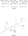
- Figure 11 is an isometric view of a bayonet flange 132 of a nose cone 110 in accordance with some embodiments of the present disclosure.
- the axially forward facing surface 1109 of retaining lip 137 may be laterally or radially tapered. Tapering of the surface 1109 may assist in engagement between the bayonet flange 132 and bayonet retainer 142.
- the tapered surface 1109 may use linear or parabolic tapers. The taper may be machined into the surface during manufacturing or may be added as a separate molded part which is bonded to the bayonet flange 132.
- a nose cone assembly 100 which eliminates the use of a support ring and fasteners when coupling nose cone 110 to hub 120 by employing a snap fit configuration.
- Figure 12 is an isometric view of a nose cone 110 in accordance with some embodiments of the present disclosure.
- Figure 13 is an isometric view of a hub 120 configured to be coupled to the nose cone 110 illustrated in Figure 12 , in accordance with some embodiments of the present disclosure.
- Nose cone 110 has one or more hub mounting members 1201 extending from a radially inner surface 1202 of flange member 114.
- the at least one hub mounting member 1201 extends from an annular mounting member 113 which is formed on or integral to the radially inner surface 1202.
- a single annular hub mounting member 1201 may be provided.
- a plurality of distinct hub mounting member 1201 are spaced about the circumference of the radially inner surface 1202 proximate the base portion 119.
- the at least one hub mounting member 1201 extends from the annular hub mating surface 118.
- Each hub mounting member 1201 of nose cone 110 comprises a flexible flange 1203 extending inwardly from flange member 114 and/or mounting member 113, and a protruding ridge 1204.
- the protruding ridge 1204 extends from a radially outward facing surface 1205 of the flexible flange 1203 and is configured to be received in a corresponding groove 1305 of the hub 120.
- flexible flange 1203 and/or protruding ridge 1204 include lead-in features such as a chamfered edge to assist in flexible flange 1203 deflection upon engagement with hub 120.
- protruding ridge 1204 may be shortened to comprise a protruding nub.
- Hub 120 comprises a rotor 121 with a plurality of blades 123 extending radially outward therefrom.
- the forward portion of the rotor 121 may comprise a planar mounting surface 145.
- the axially forward portion of the rotor 121 comprises an annular mounting portion 1301 which extends radially inward from rotor 121 and has an annular mounting surface 1303.
- the annular mounting surface 1303 defines a one or more grooves 1305 that may be sized and configured to receive a protruding ridge 1204 of the nose cone 110.
- a single groove 1305 extends continuously about the mounting surface 1303.
- a plurality of discrete grooves 1305 is defined by mounting surface 1303.
- annular mounting surface 1303 is a continuous surface around the circumference of the rotor 121, as shown in Figure 13 .
- the mounting portion 1301 is segmented into a plurality of discreet mounting portions 1301 which are spaced about the circumference of rotor 121.
- the nose cone 110 of Figure 12 may be coupled to the hub 120 of Figure 13 .
- nose cone 110 is positioned axially forward of hub 120 with each of the one or more protruding ridges 1204 axially aligned with a respective one of the one or more grooves 1305.
- Nose cone 110 is then moved axially aft such that protruding ridges 1204 first contact mounting surface 1303, causing flexible flanges 1203 to deflect inwardly (i.e. toward the central axis).
- protruding ridges 1204 engage grooves 1305, which eases the deflection of flexible flanges 1203.
- protruding ridges 1204 Once protruding ridges 1204 are engaged with grooves 1305, the axial motion of nose cone 110 is ceased. In this position flexible flanges 1203 remain deflected inward as compared to their non-engaged state shown in Figure 12 . This deflection of flexible flanges 1203 creates strain, which aides in holding nose cone 110 to hub 120.
- Flexible flanges 1203 must be sized and formed of material to provide suf ficient strain to allow nose cone 110 to remain coupled to hub 120 under all operating conditions. In rotating embodiments, centrifugal forces acting on flexible flange 1203 may impart additional holding force as the flexible flange 1203 is pushed radially outward and thus exerts increased force on the hub 120. Additionally, it is noted that the engagement of protruding ridges 1204 to a respective groove 1305 holds nose cone 110 in a steady circumferential position relative to the hub 120.
- the radial displacement force imparted by a deflected flexible flange 1203 on hub 120 must be sufficient to withstand maximum operating loads. As with most nose cone designs, this includes the maximum loading experienced during a bird strike.
- the flexible flanges 1203 may be configured to impart sufficient radial displacement force such that decoupling of the nose cone 110 and hub 120 is only possible under loading from an assembly/disassembly tool. Such a tool may engage the nose cone 110 via trim balance apertures 160 in surface 112.
- Figure 14A is a partial sectional view of the nose cone 110 of Figure 12 coupled to the hub 120 of Figure 13 , shown along a plane intersecting one of the one or more hub mounting members 1201, in accordance with some embodiments of the present disclosure.
- Hub mounting member 1201 comprises flexible flange 1203 and protruding ridge 1204. As shown in Figure 14A , when nose cone 110 is properly coupled to hub 120, protruding ridge 1204 is engaged with groove 1305 and flexible flange 1203 is inwardly deflected as compared to its unengaged position in Figure 12 .
- Figure 14B is a partial sectional view of the nose cone 110 of Figure 12 coupled to the hub 120 of Figure 13 , shown along plane which does not intersect a hub mounting member 1201 but which does intersect an aperture 160, in accordance with some embodiments of the present disclosure.
- an aperture 160 is provided through flange member 114 and mounting member 113 for the placement of balancing weights 162.
- a bolt 161 and retaining nut 163 may be used to secure the balancing weight 162 in position.
- balancing weights 162 of varying masses may be placed in aperture 160 to ensure an evenly distributed nose cone mass, which assists with stable rotation of the nose cone 110 during operation.
- a plurality of apertures 160 are provided in nose cone 110.
- nose cone 110 further defines a countersink 164 around the aperture 160 configured to receive the balancing weight 162.
- Figure 15 provides a partial profile view of the inner surface of a rotor 121 having a plurality of discreet mounting portions 1301 according to some embodiments of the present disclosure.
- Figure 13 illustrates a rotor 121 having a continuous mounting portion 1301 and continuous circumferential groove 1305
- the embodiment illustrated in Figure 15 shows a rotor 121 having a plurality of discrete mounting portions 1301, with each of the plurality of discrete mounting portions defining a respective groove 1305.
- the view provided in Figure 15 is looking radially outward from the central axis.
- a plurality of mounting portions 1301 are formed on and extend inwardly from the inner surface of the rotor 121.
- Each mounting portion 1301 comprises a mounting surface 1303 which defines a groove 1305 configured to receive a corresponding protruding ridge 1204 of nose cone 110.
- guide channels 1307 are provided which assist in guiding a protruding ridge 1204 to the groove 1305. Relative to the depth of groove 1305, the guide channels 1307 are shallow.
- the nose cone 110 of Figure 12 and the hub 120 of Figure 13 will further include one or more circumferential alignment features.
- one or more mounting flanges 901 as described above may extend forward from the hub 120 and be joined with a fastener to nose cone 110 to ensure circumferential alignment of nose cone 110 relative to hub 120.
- an alignment flange 1601 may extend aft from the nose cone 110 and be disposed, when nose cone 110 is coupled to hub 120, in or between an alignment tab 1602 of the hub 120.
- nose cone 110 may require special tooling.
- nose cone 110 defines a plurality of apertures 160
- an annular tool is contemplated which would engage simultaneously each of the one or more positioning rods disposed in apertures 160 to apply equal pressure around the nose cone 110.
- the nose cone and nose cone assemblies presented herein provide several advantages over the prior art.
- Second, the disclosed nose cone allows for coupling to the hub with a greatly reduced number of bolts or no bolts at all.
- the weight of the unit and the complexity of the coupling process are each reduced.
- a system for coupling a nose cone to a hub which eliminates the need for fingers or flanges extending axially forward from the hub. Since these fingers or flanges are difficult to manufacture with sufficient strength tolerances, their elimination is advantageous over prior art designs.
Landscapes
- Engineering & Computer Science (AREA)
- Chemical & Material Sciences (AREA)
- Combustion & Propulsion (AREA)
- Mechanical Engineering (AREA)
- General Engineering & Computer Science (AREA)
- Aviation & Aerospace Engineering (AREA)
- Structures Of Non-Positive Displacement Pumps (AREA)
- Turbine Rotor Nozzle Sealing (AREA)
- Life Sciences & Earth Sciences (AREA)
- Sustainable Development (AREA)
- Sustainable Energy (AREA)
- Physics & Mathematics (AREA)
- Fluid Mechanics (AREA)
Abstract
Description
- The present disclosure relates generally to turbine machines, and more specifically to a nose cone assembly for a turbine machine.
- Turbine machines provide energy for a wide range of uses. A turbine machine comprises at least a rotatable shaft and a plurality of blades. In some applications the plurality of blades comprises a fan. Examples of turbine machines include turbofan, turbojet, turboshaft, and turboprop engines; gas turbine engines; and wind turbines.
- The energy produced by a turbine machine is generally either electrical or mechanical. As one example, turbine machines are used to provide propulsion to an aircraft. A typical turbine engine comprises a compressor, a combustor, a high-pressure turbine, and a low-pressure turbine.
- In some turbine machines, particularly in turbine engines used for aircraft applications, it is desirable to attach a nose cone upstream from the plurality of blades of the turbine machine. Nose cones are sometimes referred to in the art as "intake cones," "inlet cones," "nose cowls," or "spinners." The nose cone can serve to reduce drag caused by the turbine machine, improve air flow to the plurality of blades, and avoid or limit damage potentially caused by impinging foreign objects. In supersonic aircraft, a nose cone is also advantageously used to slow the flow of air from supersonic flight speed to a subsonic speed before it enters the turbine machine.
- As described below with reference to
Figures 1A and 1B , the mounting of a nose cone to the turbine machine typically requires bolting the base of the nose cone to a support ring or retaining ring. The addition of a support or retaining ring and the use of a plurality of bolts to secure the nose cone increases the weight of the turbine machine, which is undesirable as it may negatively impact turbine efficiency. Further, positioning, bolting, and balancing the nose cone is a time- and labor-intensive process. Balancing the nose cone and turbine machine is necessary to address an uneven weight distribution, and typically involves attaching balance weights to the nose cone, fan, shaft, or other part of the turbine machine. However, small turbofan engines typically have limited space to accommodate balance weights and attachment features for nose cones. -
Figure 1 is a partial sectional view of anose cone 10 connected to afan rotor 12 of an inlet fan of a gas turbine engine in accordance with conventional methods as described inU.S. Patent Application Publication No. 2011/0236217 . The illustratednose cone 10 comprises aflange member 14 which tapers to a leading cone tip (not shown) and a region proximate thetrailing edge 16 having a radial thickness greater than that of the remainder of theflange member 14. Asupport ring 18 having an axially-extendingflange 20 is connected to thefan rotor 12. Abolt 22 engages thetrailing edge 16 ofnose cone 10 to anaxial member 24 and supportring 18. One disadvantage of the configuration shown inFigure 1 and similar nose cone mounting configurations used in the art is that thetrailing edge 16 must be reinforced by increasing the thickness of thenose cone 10, which increases the weight of thenose cone 10 as well. Another disadvantage is the difficulty encountered when mounting thenose cone 10 to supportring 18, particularly when bolting thenose cone 10 to thesupport ring 18. - Another nose cone configuration is illustrated in
Figure 2. Figure 2 is a partial sectional view of anose cone 10 connected to an inlet fan of a gas turbine engine as described inU.S. Patent No. 8,540,492 . As illustrated inFigure 2 , anose cone 10 comprises aflange member 14 which axially extends from leading cone tip (not shown) to atrailing edge 13. A radiallythick mounting ring 26 is formed proximate thetrailing edge 13. Themounting ring 26 defines a plurality ofapertures 15 that are spaced apart about the circumference of themounting ring 26. One or more of the apertures may include a recessed portion 17 for holding one or more balance weights 19. Afan rotor 12 is connected to retainingring 28 having amounting flange 30. Abolt 22 extends through anaperture 15 to connectnose cone 10 to themounting flange 30. Thebolt 22 also retains balance weight 19 within the recessed portion 17. As can be appreciated, the one or more balance weights 19 may be added or removed from recessed portions 17 without dismounting thenose cone 10 from themounting flange 30. - As with
Figure 1 , thenose cone 10 ofFigure 2 can be time- and labor-intensive to properly position, secure, and balance when installing. Themany bolts 22 required around the circumference of theflange member 14, as well as the inclusion of retainingring 28 in the assembly, can substantially increase the weight of the turbine machine. - It is therefore desired in the art to have improvements to nose cones and nose cone assemblies for turbine machines which reduce the overall weight of the turbine machine and simplify the process of coupling the nose cone to the turbine machine.
- The present application discloses one or more of the features recited in the appended claims and/or the following features which, alone or in any combination, may comprise patentable subject matter.
- According to an aspect of the present disclosure, a nose cone configured to be mounted to a hub in a turbo machine comprises a flange extending radially around a central axis and axially from an apex portion of the nose cone to a base portion of the nose cone, the flange forming an annular hub mating surface at the base portion and having an outer surface defining an air flow path; and a plurality of hub mounting elements each comprising one or more flexible spring flanges disposed around the circumference of the base portion, each of the flexible spring flanges forming a hub engaging surface parallel to and facing in the same direction as the hub mating surface; and one or more bayonet flanges disposed around the circumference of the base portion, each of the bayonet flanges forming a hub engaging surface parallel to and facing in the opposite direction as the hub mating surface. In some embodiments the nose cone further comprises one or more pilot flanges disposed around the circumference of the base portion, each of the pilot flanges forming a hub engaging surface perpendicular to the hub mating surface.
- In some embodiments the nose cone comprises an annular mounting member extending radially inward from the flange proximate the hub mating surface, the bayonet flanges and the pilot flanges extending axially from the mounting member. In some embodiments the flexible spring flanges extend radially inward from the hub mating surface. In some embodiments the flexible spring flanges comprise a feature that extends axially beyond the plane of the hub mating surface. In some embodiments the flexible spring flanges extend radially inward from the hub mating surface. In some embodiments the flexible spring flanges comprise a feature that extends axially beyond the plane of the hub mating surface. In some embodiments the flange forming an annular hub mating surface defines a plurality of apertures each configured to receive a balancing weight and balancing weight fastener therein. In some embodiments each of the one or more flexible spring flanges is removably attached to the nose cone.
- According to another aspect of the present disclosure, a nose cone assembly in a turbo machine comprises a turbo machine component comprising an annular hub extending radially around a central axis and forming a planar mounting surface, the hub comprising one or more bayonet retainers disposed around the circumference of the hub, the bayonet retainers extending radially inward from the hub and forming an engagement surface parallel to and facing the opposite direction as the mounting surface; one or more spring flange mating surfaces disposed around the circumference of the hub, the mating surfaces extending radially inward from the hub and forming an engagement surface parallel to and facing the same direction as the mounting surface; one or more pilot guides disposed around the circumference of the hub, the pilot guides extending radially inward from the hub and forming an engagement surface perpendicular to the mounting surface; and a nose cone mounted on the hub, the nose cone comprising a flange extending radially around the central axis and axially from an apex portion of the nose cone to a base portion of the nose cone, the flange forming an annular hub mating surface at the base portion and having an outer surface defining an air flow path; and a plurality of hub mounting elements comprising one or more flexible spring flanges disposed around the circumference of the base portion, each of the flexible spring flanges forming a hub engaging surface parallel to and facing in the same direction as the hub mating surface and being engaged with a respective engagement surface of a spring flange mating surface disposed on the hub; one or more bayonet flanges disposed around the circumference of the base portion, each of the bayonet flanges forming a hub engaging surface parallel to and facing in the opposite direction as the hub mating surface and being engaged with a respective engagement surface of a bayonet retainer disposed on the hub; and one or more pilot flanges disposed around the circumference of the base portion, each of the pilot flanges forming a hub engaging surface perpendicular to the hub mating surface and being engaged with a respective engagement surface of a pilot guide disposed on the hub.
- In some embodiments the planar mounting surface is the axially forwardmost extension of the hub. In some embodiments the hub comprises a plurality of blades extending radially outward from a rotor. In some embodiments the engagement of the hub engaging surface of the flexible spring flange with the spring flange mating surface of the hub results in deflection of the flexible spring flange. In some embodiments the deflection of the flexible spring flange imparts an axially opposing force between the nose cone and the hub. In some embodiments each of the one or more pilot guides define an aperture configured to receive a balancing weight. In some embodiments the nose cone assembly further comprises a balancing weight secured to the pilot guide by a fastener. In some embodiments the nose cone assembly further comprises an annular mounting member extending radially inward from the nose cone flange proximate the hub mating surface, the bayonet flanges and the pilot flanges extending axially from the mounting member. In some embodiments the flexible spring flanges extend radially inward from the hub mating surface.
- According to another aspect of the present disclosure, a method is disclosed of coupling a nose cone to a hub in a turbo machine having a central axis, the nose cone comprising a plurality of hub mounting elements disposed around a circumference of the nose cone base, the hub mounting elements including one or more flexible spring flanges, one or more bayonet flanges, and one or more pilot flanges; and the hub comprising a plurality of nose cone retention elements disposed proximate a planar mounting surface, the plurality of nose cone retention elements comprising one or more spring flange mating surfaces, one or more bayonet retainers, and one or more pilot guides; wherein the method comprises positioning the nose cone axially forward of and concentric with the hub; moving the nose cone in an axially aft direction until at least a portion of the one or more bayonet flanges is disposed axially aft of a respective one or more bayonet retainers; and rotating the nose cone to engage the one or more flexible spring flange and a respective spring flange mating surface and to engage the one or more bayonet flange and a respective bayonet retainer.
- In some embodiments the step of rotating the nose cone further engages the one or more pilot flanges and a respective pilot guide. In some embodiments the engagement of the one or more flexible spring flange with a respective spring flange mating surface results in deflection of the flexible spring flange, and wherein the deflection imparts an axially opposing force between the nose cone and the hub.
- According to another aspect of the present disclosure, a nose cone configured to be mounted to a hub in a turbo machine comprises a flange extending radially around a central axis and axially from an apex portion of the nose cone to a base portion of the nose cone, the flange forming an annular hub mating surface at the base portion and having an outer surface defining an air flow path; and a plurality of hub mounting elements comprising: one or more bayonet flanges disposed around the circumference of the base portion, each of the bayonet flanges forming a hub engaging surface parallel to and facing in the opposite direction as the hub mating surface; and two or more apertures defined by the flange forming the annular hub mating surface, each of the apertures configured to receive an fastener therethrough. In some embodiments the nose cone further comprises one or more pilot flanges disposed around the circumference of the base portion, each of the pilot flanges forming a hub engaging surface perpendicular to the hub mating surface.
- In some embodiments the nose cone comprises an annular mounting member extending radially inward from the flange proximate the hub mating surface, the bayonet flanges and the pilot flanges extending axially from the mounting member. In some embodiments each of the two or more apertures includes a countersink configured to receive a balance weight. In some embodiments each of the two or more apertures pass through the annular mounting member. In some embodiments each hub engaging surface of the one or more bayonet flanges comprises a radially tapered surface. In some embodiments the radially tapered surface comprises a parabolic taper.
- In some embodiments the flange forming an annular hub mating surface defines a plurality of apertures each configured to receive a balancing weight and balancing weight fastener therein. In some embodiments the flange extending radially around the central axis forms a parabolic outer surface of the nose cone. In some embodiments the flange extending radially around the central axis forms a frustoconical outer surface of the nose cone.
- According to another aspect of the present disclosure, a nose cone assembly in a turbo machine comprises a turbo machine component comprising an annular hub extending radially around a central axis and forming a planar mounting surface, the hub comprising: one or more bayonet retainers disposed around the circumference of the hub, the bayonet retainers extending radially inward from the hub and forming an engagement surface parallel to and facing the opposite direction as the mounting surface; two or more mounting flanges disposed around the circumference of the hub, each of the mounting flanges extending axially forward from the planar mounting surface and defining an aperture configured to receive a fastener; and one or more pilot guides disposed around the circumference of the hub, the pilot guides extending radially inward from the hub and forming an engagement surface perpendicular to the mounting surface; and a nose cone mounted on the hub, the nose cone comprising a flange extending radially around the central axis and axially from an apex portion of the nose cone to a base portion of the nose cone, the flange forming an annular hub mating surface at the base portion and having an outer surface defining an air flow path; and a plurality of hub mounting elements comprising: one or more bayonet flanges disposed around the circumference of the base portion, each of the bayonet flanges forming a hub engaging surface parallel to and facing in the opposite direction as the hub mating surface and being engaged with a respective engagement surface of a bayonet retainer disposed on the hub; two or more apertures defined by the flange forming the annular hub mating surface, each of the apertures configured to receive a fastener therethrough and being engaged with the aperture of a respective one of the mounting flanges by the fastener; and one or more pilot flanges disposed around the circumference of the base portion, each of the pilot flanges forming a hub engaging surface perpendicular to the hub mating surface and being engaged with a respective engagement surface of a pilot guide disposed on the hub.
- In some embodiments the nose cone assembly further comprises two or more fasteners, each fastener secured through a respective one of the one or more apertures defined by the flange forming the annular hub mating surface and of the one or more apertures defined by the mounting flange. In some embodiments the one or more apertures defined by the flange forming the annular hub mating surface each include a countersink configured to receive a balance weight. In some embodiments each of the one or more pilot guides define an aperture configured to receive a balancing weight. In some embodiments the nose cone assembly further comprises a balancing weight secured to the pilot guide by a fastener. In some embodiments the nose cone assembly further comprises an annular mounting member extending radially inward from the nose cone flange proximate the hub mating surface, the bayonet flanges and the pilot flanges extending axially from the mounting member. In some embodiments the hub comprises a plurality of blades extending radially outward from a rotor.
- According to another aspect of the present disclosure, a method of coupling a nose cone to a hub in a turbo machine having a central axis, the nose cone comprising a plurality of hub mounting elements disposed around a circumference of the nose cone base, the hub mounting elements including one or more bayonet flanges and one or more pilot flanges, the nose cone defining two or more nose cone apertures proximate the nose cone base; and the hub comprising a plurality of nose cone retention elements disposed proximate a planar mounting surface, the plurality of nose cone retention elements comprising one or more bayonet retainers, one or more pilot guides, and two or more mounting flanges each defining a respective mounting flange aperture; wherein the method comprises: positioning the nose cone axially forward of and concentric with the hub; moving the nose cone in an axially aft direction until at least a portion of the one or more bayonet flanges is disposed axially aft of a respective one or more bayonet retainers; and rotating the nose cone to engage the one or more bayonet flange and a respective bayonet retainer and to align each of the two or more apertures defined by the nose cone with a respective one of the two or more apertures defined by the mounting flange.
- In some embodiments the method further comprises securing the nose cone to the hub by securing a fastener through one of the nose cone apertures and a corresponding one of the mounting flange apertures. In some embodiments the step of rotating the nose cone further engages the one or more pilot flanges and a respective pilot guide.
- According to another aspect of the present disclosure, a nose cone configured to be mounted to a hub in a turbo machine comprises: a flange extending radially around a central axis and axially from an apex portion of the nose cone to a base portion of the nose cone, the flange forming an annular hub mating surface at the base portion and having an outer surface defining an air flow path; and a plurality of hub mounting elements disposed around the circumference of the base portion, each of the hub mounting elements comprising a flexible flange extending toward the central axis and having a ridge protruding from a radially outward facing surface; wherein the flexible flange is configured to deflect toward the central axis upon engagement with the hub.
- In some embodiments the flexible flange extends axially beyond the hub mating surface. In some embodiments the nose cone comprises an annular mounting member extending radially inward from the flange proximate the hub mating surface, the flexible flanges extending axially from the mounting member. In some embodiments the flexible flange extends axially beyond the hub mating surface.
- In some embodiments the flange extending radially around the central axis forms a parabolic outer surface of the nose cone. In some embodiments the flange extending radially around the central axis forms a frustoconical outer surface of the nose cone. In some embodiments the nose cone further comprises two or more apertures defined by the flange forming the annular hub mating surface, each of the apertures configured to receive an fastener therethrough. In some embodiments each of the two or more apertures include a countersink configured to receive a balance weight. In some embodiments a leading edge of the flexible flange is chamfered. In some embodiments the nose cone further comprises a circumferential alignment flange extending axially from the flange forming the annular hub mating surface. In some embodiments the nose cone further comprises a circumferential alignment flange extending axially from the mounting member.
- According to another aspect of the present disclosure, a nose cone assembly in a turbo machine comprises a turbo machine component comprising an annular hub extending radially around a central axis and forming a planar mounting surface, the hub comprising one or more mounting portions disposed around the circumference of the hub, the mounting portions extending radially inward from the hub and forming a mounting surface which defines a groove and a nose cone mounted on the hub, the nose cone comprising a flange extending radially around the central axis and axially from an apex portion of the nose cone to a base portion of the nose cone, the flange forming an annular hub mating surface at the base portion and having an outer surface defining an air flow path; and a plurality of hub mounting elements disposed around the circumference of the base portion, each of the hub mounting elements comprising a flexible flange extending toward the central axis and having a ridge protruding from a radially outward facing surface, wherein the flexible flange is configured to deflect toward the central axis upon engagement with the hub, and wherein each ridge is engaged with a groove of a respective one of the one or more mounting portions.
- In some embodiments the nose cone assembly further comprises two or more mounting flanges disposed around the circumference of the hub, each of the mounting flanges extending axially forward from the planar mounting surface and defining an aperture configured to receive a fastener; and two or more apertures defined by the flange forming the annular hub mating surface, each of the apertures configured to receive a fastener therethrough and being engaged with the aperture of a respective one of the mounting flanges by the fastener.
- In some embodiments the one or more apertures defined by the flange forming the annular hub mating surface each include a countersink configured to receive a balance weight. In some embodiments the mounting surface further defines a guide channel proximate the groove. In some embodiments the nose cone further comprises an alignment flange abutting an alignment tab of the hub. In some embodiments an engaged position of the flexible flange is inwardly deflected relative to an unengaged position. In some embodiments the hub comprises a plurality of blades extending radially outward from a rotor.
- According to yet another aspect of the present disclosure, a method is disclosed of coupling a nose cone to a hub in a turbo machine having a central axis, the nose cone comprising a plurality of hub mounting elements disposed around the circumference of a base portion of the nose cone, each of the hub mounting elements comprising a flexible flange extending toward the central axis and having a ridge protruding from a radially outward facing surface, the hub comprising one or more mounting portions disposed around the circumference of the hub, the mounting portions extending radially inward from the hub and forming a mounting surface which defines a groove; the method comprising positioning the nose cone axially forward of and concentric with the hub, with each ridge of the plurality of hub mounting elements axially aligned with a respective groove of the plurality of mounting portions; and moving the nose cone in an axially aft direction until the flexible flanges deflect in an inward direction and each ridge of the plurality of hub mounting elements is engaged in a respective groove of the plurality of mounting portions.
- In some embodiments an engaged position of the flexible flange is inwardly deflected relative to an unengaged position.
- The following will be apparent from elements of the figures, which are provided for illustrative purposes and are not necessarily to scale.
-
Figure 1 is a partial sectional view of a nose cone connected to a fan rotor of an inlet fan of a gas turbine engine. -
Figure 2 is a partial sectional view of a nose cone connected to a fan rotor of an inlet fan of a gas turbine engine. -
Figure 3A is an isometric view of a nose cone in accordance with some embodiments of the present disclosure. -
Figure 3B is a sectional view of a nose cone in accordance with some embodiments of the present disclosure. -
Figure 4 is an isometric view of a hub configured to be coupled to the nose cone illustrated inFigures 3A and 3B , in accordance with some embodiments of the present disclosure. -
Figure 5A is a partial sectional view of the nose cone ofFigures 3A and 3B coupled to the hub ofFigure 4 , shown along axis A, in accordance with some embodiments of the present disclosure. -
Figure 5B is a partial sectional view of the nose cone ofFigures 3A and 3B coupled to the hub ofFigure 4 , shown along axis B, in accordance with some embodiments of the present disclosure. -
Figure 5C is a partial sectional view of the nose cone ofFigures 3A and 3B coupled to the hub ofFigure 4 , shown along axis C, in accordance with some embodiments of the present disclosure. -
Figure 5D is a partial sectional view of the nose cone ofFigures 3A and 3B coupled to the hub ofFigure 4 , shown along axis B, in accordance with some embodiments of the present disclosure. -
Figure 6 is a partial isometric view of the base of a nose cone having a pocket configured to receive a removable spring mechanism in accordance with some embodiments of the present disclosure. -
Figure 7 is a removable spring mechanism in accordance with some embodiments of the present disclosure. -
Figure 8 is an isometric view of a nose cone in accordance with some embodiments of the present disclosure. -
Figure 9 is an isometric view of a hub configured to be coupled to the nose cone illustrated inFigure 8 , in accordance with some embodiments of the present disclosure. -
Figure 10A is a partial sectional view of the nose cone ofFigure 8 coupled to the hub ofFigure 9 , shown along axis A, in accordance with some embodiments of the present disclosure. -
Figure 10B is a partial sectional view of the nose cone ofFigure 8 coupled to the hub ofFigure 9 , shown along axis B, in accordance with some embodiments of the present disclosure. -
Figure 10C is a partial sectional view of the nose cone ofFigure 8 coupled to the hub ofFigure 9 , shown along axis C, in accordance with some embodiments of the present disclosure. -
Figure 10D is a partial sectional view of the nose cone ofFigure 8 coupled to the hub ofFigure 9 , shown along axis D, in accordance with some embodiments of the present disclosure. -
Figure 11 is an isometric view of a bayonet flange of a nose cone in accordance with some embodiments of the present disclosure. -
Figure 12 is an isometric view of a nose cone in accordance with some embodiments of the present disclosure. -
Figure 13 is an isometric view of a hub configured to be coupled to the nose cone illustrated inFigure 12 , in accordance with some embodiments of the present disclosure. -
Figure 14A is a partial sectional view of the nose cone ofFigure 12 coupled to the hub ofFigure 13 , shown along a plane intersecting one of the one or more hub mounting members, in accordance with some embodiments of the present disclosure. -
Figure 14B is a partial sectional view of the nose cone ofFigure 12 coupled to the hub ofFigure 13 , shown along plane which does not intersect a hub mounting member but which does intersect an aperture, in accordance with some embodiments of the present disclosure. -
Figure 15 is a partial profile view of the inner surface of a rotor having a plurality of discreet mounting portions in accordance with some embodiments of the present disclosure. -
Figure 16 is a partial sectional view of the nose cone ofFigure 12 coupled to the hub ofFigure 13 in accordance with some embodiments of the present disclosure. - While the present disclosure is susceptible to various modifications and alternative forms, specific embodiments have been shown by way of example in the drawings and will be described in detail herein. It should be understood, however, that the present disclosure is not intended to be limited to the particular forms disclosed. Rather, the present disclosure is to cover all modifications, equivalents, and alternatives falling within the spirit and scope of the disclosure as defined by the appended claims.
- For the purposes of promoting an understanding of the principles of the disclosure, reference will now be made to a number of illustrative embodiments illustrated in the drawings and specific language will be used to describe the same.
- As used herein, a turbine machine is understood to reference any machine using a turbine including gas turbine engines, wind turbines, steam turbines, water turbines, and the like. A turbine machine comprises at least a rotatable shaft and a plurality of blades.
- The nose cone herein disclosed may be appropriately coupled to a rotating or a non-rotating component. Although the embodiments herein disclose the nose cone coupled to a bladed rotor which is rotatable, one of skill in the art would recognize that the disclosed nose cone is equally suitable for coupling to a non-rotating component. One of skill in the art would additionally recognize that the disclosed
nose cones 110 andnose cone assemblies 100 could be used on a wide range of machines, including aircraft engines, non-rotating aircraft components, missiles, and UAVs. - The present disclosure is directed to a nose cone and nose cone assembly for reducing the weight and complexity required to mount the nose cone to a turbine machine. Although the disclosed nose cone is advantageously used with any number of turbine machines, the embodiments below may describe the nose cone as used with a turbine engine, such as a gas turbine engine for aviation applications. However, one of skill in the art would understand that the disclosed apparatus, systems, and methods are not so limited.
- This disclosure presents embodiments to overcome the aforementioned deficiencies of nose cones and nose cone mounting configurations. More specifically, this disclosure is directed to a nose cone, nose cone assembly, and shaft balancing assembly which reduce the weight and complexity of mounting or coupling the nose cone. Detailed descriptions of the disclosed nose cone, nose cone assembly, and shaft balancing assembly, and additional advantages thereof, are presented below.
-
Figure 3A is an isometric view of anose cone 110 andFigure 3B is a sectional view of thenose cone 110 in accordance with some embodiments of the present disclosure.Nose cone 110 comprises aflange member 114 which terminates at an annularhub mating surface 118 at thebase portion 119 ofnose cone 110.Flange member 114 has anouter surface 112 which defines an air flow path around thenose cone 110.Flange member 114 may comprise an annular mountingmember 113 which extends radially inward fromflange member 114 proximate thehub mating surface 118.Flange member 114 further extends radially about a central axis to form a hollow cone structure. In someembodiments flange member 114 may form a frustoconicalouter surface 112, while in other embodiments flange member may form a parabolicouter surface 112.Flange member 114 may be referred to as the nose cone body. -
Flange member 114 extends axially from anapex portion 111 tobase portion 119. In someembodiments flange member 114 extends forward to integrally form a leadingtip 116 of thenose cone 110. In other embodiments, such as the embodiment shown inFigures 3A and 3B theflange member 114 terminates atapex portion 111 with a radially inward extendingmember 115 and anose cone tip 117 is removably mounted to themember 115. Thus in some embodiments theflange member 114 extends from a leadingtip 116 of thenose cone 110 to ahub mating surface 118, whereas in other embodiments theflange member 114 extends from a radially inward extendingmember 115 to ahub mating surface 118.Nose cone 110 may be formed of metallic or composite materials. - In some
embodiments mounting member 113 may be circumferentially segmented such that the full radial thickness of themember 113 is not present at all positions around the circumference of theflange member 114. In other words, in some embodiments the radially inward facingsurface 125 of the mountingmember 113 has a constant diameter around the circumference, while in other embodiments the radially inward facingsurface 125 has varying diameters. Reductions in the radial thickness of the mountingmember 113 may be made as a weight saving alteration. - Mounting
member 113 and/orhub mating surface 118 may have a plurality ofhub mounting elements 130 disposed circumferentially about the mountingmember 113 and/orhub mating surface 118.Hub mounting elements 130 are configured to engage ahub 120.Hub mounting elements 130 include, but are not limited to, aflexible spring flange 131, abayonet flange 132, and apilot flange 133.Hub mounting elements 130 are spaced about the circumference of the mountingmember 113 and/orhub mating surface 118 as indicated by the axes labeled A, B, and C. In some embodimentsflexible spring flange 131 extends radially inward from thehub mating surface 118 whilebayonet flange 132 andpilot flange 133 extend axially aft from mountingmember 113. - Sectional views of the
nose cone 110 coupled to thehub 120 as intersected by a plane along the axes A, B, and C are presented inFigures 5A ,5B, and 5C . The coupling ofnose cone 110 tohub 120 forms anose cone assembly 100. - In some embodiments the positioning of the
hub mounting elements 130 is symmetrical, such that anelement 130 at one intersection of axis A and thehub mating surface 118 is the same as anelement 130 at the opposite intersection of axis A and thehub mating surface 118. However, in some embodiments thehub mounting elements 130 are not symmetrically positioned, such that the opposite intersection of axis A and thehub mating surface 118 may have adifferent mounting element 130 or no mountingelement 130. - At a first circumferential position identified by the intersection of axis A and the
hub mating surface 118, aflexible spring flange 131 is coupled to thehub mating surface 118.Spring flange 131 comprises a radially inward extendingmember 135 which may have a varying axial thickness. In the illustrated embodiment, for example, themember 135 is relatively thicker in the axial dimension at the radially inward end.Member 135 has ahub engaging surface 138 which may be parallel to and facing the same direction ashub mating surface 118. In some embodiments springflange 131 comprises amember 135 which extends radially inward from and axially beyond the plane of thehub mating surface 118. -
Spring flange 131 is configured to provide a biasing force in the axial direction. Whennose cone 110 is coupled tohub 120,spring flange 131 provides an axial separation force between thenose cone 110 andhub 120. In some embodiments springflange 131 may include lead-in features such as chamfers to aid the coupling ofnose cone 110 tohub 120. - During the coupling process of the
nose cone 110 to thehub 120, thespring flange 131 is configured to deflect as the peak assembly displacement is greater than the axial displacement provided by thespring flange 131 once fully assembled. In some embodiments the thickness ofspring flange 131 is adapted to provide a desired axial displacement force. In some embodiments thespring flange 131 may include a protruding and/or mating receptacle feature configured to engage once thenose cone 110 andhub 120 are correctly circumferentially positioned during assembly. Such a feature aids in maintaining circumferential alignment between thenose cone 110 andhub 120 during operation. - The axial displacement force imparted by the one or
more spring flanges 131 disposed about thebase portion 119 ofnose cone 110 must be sufficient to withstand maximum operating loads. As with most nose cone designs, this includes the maximum loading experienced during a bird strike. The spring flanges 131 may be configured to impart sufficient axial displacement force such that decoupling of thenose cone 110 andhub 120 is only possible under loading from an assembly/disassembly tool. Such a tool may engage thenose cone 110 via trim balance apertures insurface 112. - At a second circumferential position identified by the intersection of axis B and the
hub mating surface 118, abayonet flange 132 extends from the mountingmember 113.Bayonet flange 132 comprises anaxially extending member 136 and a retaininglip 137. Retaininglip 137 has ahub engaging surface 139 which may be parallel to and facing in the opposite direction as thehub mating surface 118.Bayonet flange 132 is configured to engage a portion ofhub 120 resulting in the axial retention ofnose cone 110. In some embodiments bayonetflange 132 may include lead-in features such as chamfers to aid the coupling ofnose cone 110 tohub 120. - At a third circumferential position identified by the intersection of axis C and the
hub mating surface 118, apilot flange 133 extends from the mountingmember 113. As illustrated,pilot flange 133 extends axially aft from the mountingmember 113 and is configured to engage a portion ofhub 120 to maintain concentricity ofnose cone 110 tohub 120.Pilot flange 133 has ahub engaging surface 134 which may be perpendicular to thehub mating surface 118. - One or more
flexible spring flanges 131 may be disposed about the circumference ofbase portion 119. One ormore bayonet flanges 132 may be disposed about the circumference ofbase portion 119. One ormore pilot flanges 133 may be disposed about the circumference ofbase portion 119. -
Figure 4 is an isometric view of ahub 120 configured to be coupled to thenose cone 110 illustrated inFigures 3A and 3B , in accordance with some embodiments of the present disclosure. In the illustrated embodiment,hub 120 is a bladed rotor of a turbine machine. However, in other embodiments thehub 120 may be another component of a turbine machine including a static (i.e. non-rotating) component. - In the illustrated embodiment,
hub 120 comprises a hollowcylindrical rotor 121 which extends radially about a central axis and has a plurality ofblades 123 extending radially therefrom. An axially aft portion of therotor 121 may comprise amating flange 124 configured to couple therotor 121 to a rotating shaft (not shown). An axially forward portion of therotor 121 may comprise a plurality of nosecone retention elements 140 configured to retain thenose cone 110 described with reference toFigures 3A and 3B . Nosecone retention elements 140 may include one or more spring flange mating surfaces 141,bayonet retainers 142, and pilot guides 143. Nosecone retention elements 140 may be circumferentially disposed about the forward portion of therotor 121 and may be spaced apart bygaps 144. The forward portion of therotor 121 may comprise a planar mountingsurface 145. - Spring flange mating surfaces 141 are configured to
abut spring flanges 131 whennose cone 110 is coupled tohub 120. Eachspring flange 131 is aligned with a respective springflange mating surface 141 and pushes against the springflange mating surface 141 to impart axial force onnose cone 110. -
Bayonet retainers 142 are configured to retainbayonet flanges 132 ofnose cone 110 whennose cone 110 is coupled tohub 120. Eachbayonet flange 132 is aligned with arespective bayonet retainer 142.Bayonet retainers 142 extend radially inward fromrotor 121 such that theretention lip 137 of abayonet flange 132 will engage thebayonet retainer 142 and axially forward motion of thenose cone 110 will be prevented. - Pilot guides 143 are configured to
abut pilot flanges 133 in order to maintain concentricity ofnose cone 110 tohub 120. In some embodiments pilot guides 143 comprise aradially extending portion 146 and anaxially extending portion 147. Theaxially extending portion 147 is configured to engage thepilot flange 133 whennose cone 110 is coupled tohub 120. Eachpilot flange 133 is aligned with arespective pilot guide 143. Theradially extending portion 146 may include anaperture 148 configured to receive balancingweights 149. - In some embodiments an axially forward facing planar mounting
surface 145 represents the forwardmost extension of therotor 121. In some embodiments one or more of the nosecone retention elements 140 are integral to mountingsurface 145. - The
nose cone 110 described above with reference toFigures 3A and 3B may be coupled to thehub 120 described above with reference toFigure 4 . To couple thenose cone 110 andhub 120, thenose cone 110 must be positioned axially forward from thehub 120 withbayonet flanges 132 circumferentially aligned withgaps 144 between the nosecone retention elements 140 ofhub 120.Nose cone 110 may then be moved axially aft such that theretention lip 137 of eachbayonet flange 132 is axially aft of thebayonet retainers 142 of thehub 120.Nose cone 110 may then be rotated to engage eachbayonet flange 132 with arespective bayonet retainer 142. In some embodiments, it will be essential that theretention lips 137 of thebayonet flanges 132 begin to engage theirrespective bayonet retainer 142 prior to engagement of thespring flanges 131. This will allow theretention lips 137 to be axially engaged withhub 120 prior to the axial separating force being imparted by thespring flanges 131, and thus prevent separation ofnose cone 110 fromhub 120. -
Figures 5A ,5B ,5C , and5D provide sectional views of anose cone 110 coupled to ahub 120. -
Figure 5A is a partial sectional view of thenose cone 110 ofFigures 3A and 3B coupled to thehub 120 ofFigure 4 , shown along axis A, in accordance with some embodiments of the present disclosure. When coupled,spring flange 131 abuts an opposing springflange mating surface 141. When abutting the springflange mating surface 141,spring flange 131 is flexed thus imparting an axially forwarded force onnose cone 110. Eachspring flange 131 is aligned with a respective springflange mating surface 141 and pushes against the springflange mating surface 141 to impart axial force onnose cone 110. -
Figure 5B is a partial sectional view of thenose cone 110 ofFigures 3A and 3B coupled to thehub 120 ofFigure 4 , shown along axis B, in accordance with some embodiments of the present disclosure.Retention lip 137 ofbayonet flange 132 is engaged axially aft ofbayonet retainer 142, thus preventing axially forward movement ofnose cone 110. In some embodimentshub mating surface 118 may abutrotor 121. -
Figure 5C is a partial sectional view of thenose cone 110 ofFigures 3A and 3B coupled to thehub 120 ofFigure 4 , shown along axis C, in accordance with some embodiments of the present disclosure.Pilot flange 133 abuts theaxially extending portion 147 ofpilot guide 143 to ensure the proper disposition ofnose cone 110 relative tohub 120. In rotating embodiments, the abutment ofpilot guide 143 andpilot flange 133 ensures proper concentricity ofnose cone 110 tohub 120. - In some embodiments an
aperture 148 may be defined by radially extendingportion 146 of thepilot guide 143 and may be configured to receive one ormore balancing weights 149 which may be coupled topilot guide 143 with a fastener. Duringnose cone 110 balancing, balancingweights 149 of varying masses may be placed inaperture 148 to ensure an evenly distributed nose cone mass, which assists with stable rotation of thenose cone 110 during operation. In some embodiments a plurality ofapertures 148 are provided, each defined by arespective pilot guide 143. -
Figure 5D is a partial sectional view of thenose cone 110 ofFigures 3A and 3B coupled to thehub 120 ofFigure 4 , shown along axis B, in accordance with some embodiments of the present disclosure.Retention lip 137 ofbayonet flange 132 is engaged axially aft ofbayonet retainer 142, thus preventing axially forward movement ofnose cone 110. In some embodimentshub mating surface 118 may abutrotor 121. - In the embodiment illustrated in
Figure 5D , anaperture 160 is provided through mountingmember 113 for the placement of balancingweights 162. Abolt 161 and retainingnut 163 may be used to secure the balancingweight 162 in position. Duringnose cone 110 balancing, balancingweights 162 of varying masses may be placed inaperture 160 to ensure an evenly distributed nose cone mass, which assists with stable rotation of thenose cone 110 during operation. In some embodiments a plurality ofapertures 160 are provided innose cone 110. In someembodiments nose cone 110 further defines acountersink 164 around theaperture 160 configured to receive the balancingweight 162. - In some
embodiments balancing weight 162 is omitted, and balancing of thenose cone 110 is achieved using fasteners of varying lengths and thus of varying weights. This balancing method allows for reduction of the diameter of thecountersink 164, and thus the reduction of the reinforcement required in the vicinity ofcountersink 164. Reducing the thickness offlange member 114 and/or mountingmember 113 reduces the weight ofnose cone 110. - In some embodiments, the manufacture of
nose cone 110 is simplified by omitting thespring flanges 131 during initial manufacture.Spring flanges 131 are then added tonose cone 110 prior to coupling withhub 120.Figure 6 is a partial isometric view of thebase portion 119 of anose cone 110 having apocket 601 configured to receive aremovable spring mechanism 701 in accordance with some embodiments of the present disclosure. Thepocket 601 is formed in thesurface 112 offlange 114, and in some embodiments defines anaperture 603.Figure 7 is aremovable spring mechanism 701 configured to be inserted into thepocket 601 in accordance with some embodiments of the present disclosure. In some embodiments,spring mechanism 701 may be configured to partially rest inpocket 601 and be secured with a fastener through aspring mechanism hole 703 and theaperture 603. In other embodiments,spring mechanism 701 may be configured to be inserted at least partially through theaperture 603 and may be secured in place with or without a fastener. In someembodiments spring mechanism 701 may be secured through theaperture 603 with an adhesive. - In some embodiments of the present disclosure, a
nose cone assembly 100 is provided which significantly reduces the number of fasteners required to couplenose cone 110 tohub 120. For example,Figure 8 is an isometric view of anose cone 110 in accordance with some embodiments of the present disclosure. In the embodiment illustrated inFigure 8 ,nose cone 110 has a plurality ofhub mounting elements 130 including a plurality ofbayonet flanges 132 and, in some embodiments, a plurality ofpilot flanges 133.Hub mounting elements 130 are configured to engagehub 120 and to retain coupling ofnose cone 110 tohub 120.Hub mounting elements 130 are spaced about the circumference of the mountingmember 113 orhub mating surface 118 as indicated by axes A and B. Sectional views of thenose cone 110 coupled tohub 120 as intersected by a plane along axes A, B, and C are presented inFigures 10A ,10B, and 10C . - The
nose cone 110 ofFigure 8 additionally has at least a pair ofapertures 801 which pass through theflange member 114 and mountingmember 113.Apertures 801 are configured to receive a fastener there through for coupling thenose cone 110 to ahub 120.Apertures 801 are located along an axial plane extending from axis A. Additionally a plurality ofbayonet flanges 132 are spaced about the circumference of the mountingmember 113, and at least onebayonet flange 132 is disposed in an axial plane extending from axis B. -
Figure 9 is an isometric view of ahub 120 configured to be coupled to thenose cone 110 illustrated inFigure 8 , in accordance with some embodiments of the present disclosure.Hub 120 is illustrated inFigure 9 as a bladed rotor; however, thehub 120 may take the form of other engine components including non-rotating components. -
Hub 120 comprises arotor 121 with a plurality ofblades 123 extending radially outward therefrom. The axially forward portion of therotor 121 comprises a plurality of nosecone retention elements 140 configured to engage thehub mounting elements 130 of thenose cone 110 and therefore retain coupling between thenose cone 110 andhub 120. Nosecone retention elements 140 in the illustrated embodiment include one or more of a mountingflange 901, abayonet retainer 142, and pilot guides 143. Nosecone retention elements 140 may be circumferentially disposed about the forward portion ofrotor 121 and may be spaced apart by gaps. - Each mounting
flange 901 extends axially forward from the axially forward portion of therotor 121 and defines a mountingaperture 903. The mountingflange 901 may be sized and configured such that the mountingaperture 903 aligns with one of theapertures 801 of thenose cone 110 whennose cone 110 is properly coupled tohub 120. A fastener such as a bolt or screw is able to be passed throughaperture 801 and mountingaperture 903 in order to securenose cone 110 tohub 120. Mountingflanges 901 thus serve primarily to prevent either axial or circumferential motion ofnose cone 110 relative tohub 120. By preventing circumferential motion ofnose cone 110 relative tohub 120, mountingflanges 901 ensure continuous engagement ofbayonet flanges 132 tobayonet retainers 142. - In the illustrated embodiment a pair of mounting
flanges 901 is provided withhub 120 and configured to align with a pair ofapertures 801. In some embodiments only asingle mounting flange 901 andaperture 801 are provided. In other embodiments, more than two mountingflanges 901 andapertures 801 are provided. - As described above,
bayonet retainers 142 and pilot guides 143 are configured to engagebayonet flanges 132 andpilot flanges 133, respectively.Bayonet flanges 132 andbayonet retainers 142 are configured to reduce the load capability requirements on the mountingflanges 901 described above. - The
nose cone 110 described above with reference toFigure 8 may be coupled to thehub 120 described above with reference toFigure 9 . To couple thenose cone 110 andhub 120, thenose cone 110 must be positioned axially forward from thehub 120 withbayonet flanges 132 circumferentially aligned withgaps 144 between the nosecone retention elements 140 ofhub 120.Nose cone 110 may then be moved axially aft such that theretention lip 137 of eachbayonet flange 132 is axially aft of thebayonet retainers 142 of thehub 120.Nose cone 110 may then be rotated to engage eachbayonet flange 132 with arespective bayonet retainer 142. Rotating thenose cone 110 into proper alignment withhub 120 will serve to (1) engage thebayonet flanges 132 to thebayonet retainers 142, (2) alignapertures 801 with arespective aperture 903, and (3) engagepilot flanges 133 to theaxially extending portion 147 ofpilot guide 143. A fastener is then passed through theaperture 801 andaperture 903 and secured to complete the coupling ofnose cone 110 tohub 120. - The use of a plurality of
bayonet flanges 132 andbayonet retainers 142 when couplingnose cone 110 tohub 120 advantageously allows for reduction of fasteners as compared to the prior art. Reducing the number of bolts which pass through thenose cone 110 allows for reduction in the overall weight of the nose cone assembly, both by reducing the heavy bolts used to couplenose cone 110 tohub 120 and by reducing the amount of reinforcement required around the receiving apertures in thenose cone 110. Further, ease of manufacture is improved by reducing the number of receiving apertures which are required to pass through the base of thenose cone 110. The ease of assembly may also be improved as fewer fasteners are required to securenose cone 110 tohub 120. -
Figures 10A ,10B ,10C , and10D provide sectional views of anose cone 110 coupled to ahub 120.Figure 10A is a partial sectional view of the coupling of the nose cone ofFigure 8 and thehub 120 ofFigure 9 , shown along axis A, in accordance with some embodiments of the present disclosure. - In some embodiments a balancing
weight 162 may be included when securingnose cone 110 tohub 120 with abolt 161. Abolt 161 and retainingnut 163 may be used to secure the balancingweight 162 in position. Duringnose cone 110 balancing, balancingweights 162 of varying masses may be placed inaperture 160 to ensure an evenly distributed nose cone mass, which assists with stable rotation of thenose cone 110 during operation. In some embodiments a plurality ofapertures 160 are provided innose cone 110. -
Figure 10B is a partial sectional view of the coupling of the nose cone ofFigure 8 and thehub 120 ofFigure 9 , shown along axis B, in accordance with some embodiments of the present disclosure.Retention lip 137 ofbayonet flange 132 is engaged axially aft ofbayonet retainer 142, thus preventing axially forward movement ofnose cone 110. In some embodimentshub mating surface 118 may abutrotor 121. -
Figure 10C is a partial sectional view of the coupling of the nose cone ofFigure 8 and thehub 120 ofFigure 9 , shown along axis C, in accordance with some embodiments of the present disclosure.Pilot flange 133 abuts theaxially extending portion 147 ofpilot guide 143 to ensure the proper disposition ofnose cone 110 relative tohub 120. In rotating embodiments, the abutment ofpilot guide 143 andpilot flange 133 ensures proper concentricity ofnose cone 110 tohub 120. In some embodiments anaperture 148 may be defined by radially extendingportion 146 of thepilot guide 143 and may be configured to receive one ormore balancing weights 149 which may be coupled topilot guide 143 with a fastener. -
Figure 10D is a partial sectional view of the coupling of the nose cone ofFigure 8 and thehub 120 ofFigure 9 , shown along axis D, in accordance with some embodiments of the present disclosure.Retention lip 137 ofbayonet flange 132 is engaged axially aft ofbayonet retainer 142, thus preventing axially forward movement ofnose cone 110. In some embodimentshub mating surface 118 may abutrotor 121. In the embodiment illustrated inFigure 5D , anaperture 160 is provided through mountingmember 113 for the placement of balancingweights 162. Abolt 161 and retainingnut 163 may be used to secure the balancingweight 162 in position. -
Figure 11 is an isometric view of abayonet flange 132 of anose cone 110 in accordance with some embodiments of the present disclosure. In some embodiments the axially forward facingsurface 1109 of retaininglip 137 may be laterally or radially tapered. Tapering of thesurface 1109 may assist in engagement between thebayonet flange 132 andbayonet retainer 142. The taperedsurface 1109 may use linear or parabolic tapers. The taper may be machined into the surface during manufacturing or may be added as a separate molded part which is bonded to thebayonet flange 132. - In some embodiments of the present disclosure a
nose cone assembly 100 is disclosed which eliminates the use of a support ring and fasteners when couplingnose cone 110 tohub 120 by employing a snap fit configuration. For example,Figure 12 is an isometric view of anose cone 110 in accordance with some embodiments of the present disclosure.Figure 13 is an isometric view of ahub 120 configured to be coupled to thenose cone 110 illustrated inFigure 12 , in accordance with some embodiments of the present disclosure. -
Nose cone 110 has one or morehub mounting members 1201 extending from a radiallyinner surface 1202 offlange member 114. In some embodiments, the at least onehub mounting member 1201 extends from an annular mountingmember 113 which is formed on or integral to the radiallyinner surface 1202. In some embodiments a single annularhub mounting member 1201 may be provided. In other embodiments, such as that illustrated inFigure 12 , a plurality of distincthub mounting member 1201 are spaced about the circumference of the radiallyinner surface 1202 proximate thebase portion 119. In still further embodiments, the at least onehub mounting member 1201 extends from the annularhub mating surface 118. - Each
hub mounting member 1201 ofnose cone 110 comprises aflexible flange 1203 extending inwardly fromflange member 114 and/or mountingmember 113, and a protrudingridge 1204. The protrudingridge 1204 extends from a radially outward facingsurface 1205 of theflexible flange 1203 and is configured to be received in acorresponding groove 1305 of thehub 120. In some embodimentsflexible flange 1203 and/or protrudingridge 1204 include lead-in features such as a chamfered edge to assist inflexible flange 1203 deflection upon engagement withhub 120. In someembodiments protruding ridge 1204 may be shortened to comprise a protruding nub. -
Hub 120 comprises arotor 121 with a plurality ofblades 123 extending radially outward therefrom. The forward portion of therotor 121 may comprise a planar mountingsurface 145. The axially forward portion of therotor 121 comprises anannular mounting portion 1301 which extends radially inward fromrotor 121 and has anannular mounting surface 1303. Theannular mounting surface 1303 defines a one ormore grooves 1305 that may be sized and configured to receive a protrudingridge 1204 of thenose cone 110. In some embodiments asingle groove 1305 extends continuously about the mountingsurface 1303. In other embodiments, a plurality ofdiscrete grooves 1305 is defined by mountingsurface 1303. - In some embodiments annular mounting
surface 1303 is a continuous surface around the circumference of therotor 121, as shown inFigure 13 . However, in some embodiments the mountingportion 1301 is segmented into a plurality ofdiscreet mounting portions 1301 which are spaced about the circumference ofrotor 121. - The
nose cone 110 ofFigure 12 may be coupled to thehub 120 ofFigure 13 . To couplenose cone 110 ofFigure 12 tohub 120 ofFigure 13 and achieve anose cone assembly 100,nose cone 110 is positioned axially forward ofhub 120 with each of the one or more protrudingridges 1204 axially aligned with a respective one of the one ormore grooves 1305.Nose cone 110 is then moved axially aft such that protrudingridges 1204 firstcontact mounting surface 1303, causingflexible flanges 1203 to deflect inwardly (i.e. toward the central axis). Asnose cone 110 continues to be moved axially aft, protrudingridges 1204 engagegrooves 1305, which eases the deflection offlexible flanges 1203. Once protrudingridges 1204 are engaged withgrooves 1305, the axial motion ofnose cone 110 is ceased. In this positionflexible flanges 1203 remain deflected inward as compared to their non-engaged state shown inFigure 12 . This deflection offlexible flanges 1203 creates strain, which aides in holdingnose cone 110 tohub 120. -
Flexible flanges 1203 must be sized and formed of material to provide suf ficient strain to allownose cone 110 to remain coupled tohub 120 under all operating conditions. In rotating embodiments, centrifugal forces acting onflexible flange 1203 may impart additional holding force as theflexible flange 1203 is pushed radially outward and thus exerts increased force on thehub 120. Additionally, it is noted that the engagement of protrudingridges 1204 to arespective groove 1305 holdsnose cone 110 in a steady circumferential position relative to thehub 120. - The radial displacement force imparted by a deflected
flexible flange 1203 onhub 120 must be sufficient to withstand maximum operating loads. As with most nose cone designs, this includes the maximum loading experienced during a bird strike. Theflexible flanges 1203 may be configured to impart sufficient radial displacement force such that decoupling of thenose cone 110 andhub 120 is only possible under loading from an assembly/disassembly tool. Such a tool may engage thenose cone 110 viatrim balance apertures 160 insurface 112. -
Figure 14A is a partial sectional view of thenose cone 110 ofFigure 12 coupled to thehub 120 ofFigure 13 , shown along a plane intersecting one of the one or morehub mounting members 1201, in accordance with some embodiments of the present disclosure.Hub mounting member 1201 comprisesflexible flange 1203 and protrudingridge 1204. As shown inFigure 14A , whennose cone 110 is properly coupled tohub 120, protrudingridge 1204 is engaged withgroove 1305 andflexible flange 1203 is inwardly deflected as compared to its unengaged position inFigure 12 . -
Figure 14B is a partial sectional view of thenose cone 110 ofFigure 12 coupled to thehub 120 ofFigure 13 , shown along plane which does not intersect ahub mounting member 1201 but which does intersect anaperture 160, in accordance with some embodiments of the present disclosure. In the embodiment illustrated inFigure 14B , anaperture 160 is provided throughflange member 114 and mountingmember 113 for the placement of balancingweights 162. Abolt 161 and retainingnut 163 may be used to secure the balancingweight 162 in position. Duringnose cone 110 balancing, balancingweights 162 of varying masses may be placed inaperture 160 to ensure an evenly distributed nose cone mass, which assists with stable rotation of thenose cone 110 during operation. In some embodiments a plurality ofapertures 160 are provided innose cone 110. In someembodiments nose cone 110 further defines acountersink 164 around theaperture 160 configured to receive the balancingweight 162. -
Figure 15 provides a partial profile view of the inner surface of arotor 121 having a plurality ofdiscreet mounting portions 1301 according to some embodiments of the present disclosure. WhereasFigure 13 illustrates arotor 121 having acontinuous mounting portion 1301 and continuouscircumferential groove 1305, the embodiment illustrated inFigure 15 shows arotor 121 having a plurality ofdiscrete mounting portions 1301, with each of the plurality of discrete mounting portions defining arespective groove 1305. The view provided inFigure 15 is looking radially outward from the central axis. A plurality of mountingportions 1301 are formed on and extend inwardly from the inner surface of therotor 121. Each mountingportion 1301 comprises a mountingsurface 1303 which defines agroove 1305 configured to receive a corresponding protrudingridge 1204 ofnose cone 110. In some embodiments,guide channels 1307 are provided which assist in guiding a protrudingridge 1204 to thegroove 1305. Relative to the depth ofgroove 1305, theguide channels 1307 are shallow. - In some embodiments, the
nose cone 110 ofFigure 12 and thehub 120 ofFigure 13 will further include one or more circumferential alignment features. For example, in some embodiments one or more mountingflanges 901 as described above may extend forward from thehub 120 and be joined with a fastener tonose cone 110 to ensure circumferential alignment ofnose cone 110 relative tohub 120. In other embodiments, such as that shown inFigure 16 , analignment flange 1601 may extend aft from thenose cone 110 and be disposed, whennose cone 110 is coupled tohub 120, in or between analignment tab 1602 of thehub 120. - Assembly of
nose cone 110 tohub 120 may require special tooling. For example, in some embodiments wherenose cone 110 defines a plurality ofapertures 160, it may be desirable to secure positioning rods in one or more of theapertures 160 to assist with positioning and moving thenose cone 110 relative tohub 120. In some embodiments an annular tool is contemplated which would engage simultaneously each of the one or more positioning rods disposed inapertures 160 to apply equal pressure around thenose cone 110. - The nose cone and nose cone assemblies presented herein provide several advantages over the prior art. First, by coupling the nose cone directly a hub such as a bladed rotor of a turbine machine, it is possible to eliminate the standard support or retaining ring and thus reduce the overall weight of the unit. Second, the disclosed nose cone allows for coupling to the hub with a greatly reduced number of bolts or no bolts at all. Thus, by reducing or eliminating the bolts used in the prior art to couple the nose cone to the hub, the weight of the unit and the complexity of the coupling process are each reduced.
- In certain of the above embodiments, a system for coupling a nose cone to a hub is provided which eliminates the need for fingers or flanges extending axially forward from the hub. Since these fingers or flanges are difficult to manufacture with sufficient strength tolerances, their elimination is advantageous over prior art designs.
- Although examples are illustrated and described herein, embodiments are nevertheless not limited to the details shown, since various modifications and structural changes may be made therein by those of ordinary skill within the scope and range of equivalents of the claims.
Claims (15)
- A nose cone (110) configured to be mounted to a hub (120) in a turbo machine, said nose cone comprising:a flange (114) extending radially around a central axis and axially from an apex portion (111) of said nose cone (110) to a base portion (119) of said nose cone (110), said flange (114) forming an annular hub mating surface (118) at said base portion (119) and having an outer surface (112) defining an air flow path; anda plurality of hub mounting elements (130) disposed around the circumference of said base portion (119), each of said hub mounting elements (130) comprising a flexible flange (1203) extending toward the central axis and having a ridge (1204) protruding from a radially outward facing surface (1205);wherein said flexible flange (1203) is configured to deflect toward the central axis upon engagement with said hub (120).
- The nose cone of the preceding claim, wherein said flexible flange (1203) extends axially beyond said hub mating surface (118) and/or wherein a leading edge of said flexible flange (1203) is chamfered.
- The nose cone of any one of the preceding claims, comprising an annular mounting member (113) extending radially inward from said flange (114) proximate said hub mating surface (118), said flexible flanges (1203) extending axially from said mounting member (113).
- The nose cone of any one of the preceding claims, wherein said flange (114) extending radially around the central axis forms a parabolic, or a frustoconical outer surface (112) of the nose cone (110).
- The nose cone of any one of the preceding claims, further comprising two or more apertures (801) defined by said flange (114) forming said annular hub mating surface (118), each of said apertures (801) configured to receive an fastener therethrough.
- The nose cone of the preceding claim, wherein each of said two or more apertures (801) include a countersink (164) configured to receive a balance weight (162).
- The nose cone of any one of the preceding claims, further comprising a circumferential alignment flange (901) extending axially from said flange (114) forming said annular hub mating surface (118).
- The nose cone of claim 3, further comprising a circumferential alignment flange (901) extending axially from said mounting member (113).
- A nose cone assembly in a turbo machine, said assembly comprising:a turbo machine component comprising an annular hub (120) extending radially around a central axis and forming a planar mounting surface (145), said hub (120) comprising:one or more mounting portions (1301) disposed around the circumference of said hub (120), said mounting portions extending radially inward from said hub (120) and forming a mounting surface (1303) which defines a groove (1305);
anda nose cone (110) mounted on said hub (120), said nose cone (110) comprising a flange (114) extending radially around the central axis and axially from an apex portion (111) of said nose cone (110) to a base portion (119) of said nose cone (110), said flange (114) forming an annular hub mating surface (118) at said base portion (119) and having an outer surface (112) defining an air flow path; anda plurality of hub mounting elements (130) disposed around the circumference of said base portion (119), each of said hub mounting elements (130) comprising a flexible flange (1203) extending toward the central axis and having a ridge (1204) protruding from a radially outward facing surface, wherein said flexible flange (1203) is configured to deflect toward the central axis upon engagement with said hub (120), and wherein each ridge (1204) is engaged with a groove (1305) of a respective one of said one or more mounting portions (1301). - The nose cone assembly of the preceding claims, further comprising two or more mounting flanges (901) disposed around the circumference of said hub (120), each of said mounting flanges (901) extending axially forward from said planar mounting surface (145) and defining an aperture (903) configured to receive a fastener; and
two or more apertures (801) defined by said flange (114) forming said annular hub mating surface (118), each of said apertures (801) configured to receive a fastener therethrough and being engaged with said aperture (903) of a respective one of said mounting flanges (901) by said fastener. - The nose cone assembly of the preceding claim, wherein said one or more apertures (801) defined by said flange (114) forming said annular hub mating surface (118) each include a countersink (164) configured to receive a balance weight (162).
- The nose cone assembly of any one of claims 9 to 11, wherein said mounting surface (1303) further defines a guide channel (1307) proximate said groove (1305) and/or wherein said nose cone (110) further comprises an alignment flange (1601) abutting an alignment tab (1602) of said hub (120).
- The nose cone assembly of any one of claims 9 to 12, wherein an engaged position of said flexible flange (1203) is inwardly deflected relative to an unengaged position and/or wherein said hub (120) comprises a plurality of blades (123) extending radially outward from a rotor (121).
- A method of coupling a nose cone (110) to a hub (120) in a turbo machine having a central axis,
said nose cone (120) comprising a plurality of hub mounting elements (130) disposed around the circumference of a base portion (119) of said nose cone (120), each of said hub mounting elements (130) comprising a flexible flange (1203) extending toward the central axis and having a ridge (1204) protruding from a radially outward facing surface (1205),
said hub (120) comprising one or more mounting portions (1301) disposed around the circumference of said hub (120), said mounting portions (1301) extending radially inward from said hub (120) and forming a mounting surface (1303) which defines a groove (1305);
the method comprising:positioning said nose cone (110) axially forward of and concentric with said hub (120), with each ridge (1204) of said plurality of hub mounting elements (130) axially aligned with a respective groove (1305) of said plurality of mounting portions (1301); andmoving said nose cone (110) in an axially aft direction until said flexible flanges (1203) deflect in an inward direction and each ridge (1204) of said plurality of hub mounting elements (130) is engaged in a respective groove (1305) of said plurality of mounting portions (1301). - The method of the preceding claim, wherein an engaged position of said flexible flange (1203) is inwardly deflected relative to an unengaged position.
Applications Claiming Priority (1)
| Application Number | Priority Date | Filing Date | Title |
|---|---|---|---|
| US15/342,526 US10507904B2 (en) | 2016-11-03 | 2016-11-03 | Snap fit nose cone assembly |
Publications (2)
| Publication Number | Publication Date |
|---|---|
| EP3318482A1 true EP3318482A1 (en) | 2018-05-09 |
| EP3318482B1 EP3318482B1 (en) | 2021-01-27 |
Family
ID=60021921
Family Applications (1)
| Application Number | Title | Priority Date | Filing Date |
|---|---|---|---|
| EP17194504.1A Active EP3318482B1 (en) | 2016-11-03 | 2017-10-03 | Snap fit nose cone assembly |
Country Status (2)
| Country | Link |
|---|---|
| US (1) | US10507904B2 (en) |
| EP (1) | EP3318482B1 (en) |
Cited By (1)
| Publication number | Priority date | Publication date | Assignee | Title |
|---|---|---|---|---|
| EP3715591A1 (en) * | 2019-03-27 | 2020-09-30 | Rolls-Royce Deutschland Ltd & Co KG | Flange coupling arrangement |
Families Citing this family (5)
| Publication number | Priority date | Publication date | Assignee | Title |
|---|---|---|---|---|
| US10823151B2 (en) * | 2018-10-05 | 2020-11-03 | Hamilton Sunstrand Corporation | Ram air turbine single-unit nose mass |
| US11421555B2 (en) * | 2018-12-07 | 2022-08-23 | Raytheon Technologies Corporation | Case flange with scallop features |
| US11143103B2 (en) * | 2019-04-10 | 2021-10-12 | Rolls-Royce Corporation | Nose cone and fan assembly |
| CN111852906B (en) * | 2019-04-28 | 2022-02-22 | 中国航发商用航空发动机有限责任公司 | Aircraft engine fan device and aircraft engine |
| US11725533B2 (en) * | 2020-11-10 | 2023-08-15 | Pratt & Whitney Canada Corp. | Variable guide vane assembly and bushing ring therefor |
Citations (6)
| Publication number | Priority date | Publication date | Assignee | Title |
|---|---|---|---|---|
| GB498157A (en) * | 1937-08-09 | 1939-01-04 | Leonard Metcalfe | Improvements in airscrew spinners and latching devices therefor |
| GB548864A (en) * | 1941-02-26 | 1942-10-28 | Alexander James Garland Waters | Improvements in and relating to spinners for airscrews |
| US3703341A (en) * | 1971-04-08 | 1972-11-21 | Dominic Garofalo | Propeller spinner for model airplanes |
| US20090214354A1 (en) * | 2008-02-26 | 2009-08-27 | Rolls-Royce Plc | Nose cone assembly |
| US20110236217A1 (en) | 2010-03-26 | 2011-09-29 | Rolls-Royce Plc | Gas turbine engine nose cone |
| US8540492B2 (en) | 2009-04-09 | 2013-09-24 | Rolls-Royce Deutschland Ltd & Co Kg | Intake cone in a fiber compound material for a gas-turbine engine |
Family Cites Families (17)
| Publication number | Priority date | Publication date | Assignee | Title |
|---|---|---|---|---|
| US1540506A (en) * | 1923-06-22 | 1925-06-02 | Frederick A Watkins | Sound transmitter |
| CH453955A (en) * | 1966-03-04 | 1968-03-31 | Oerlikon Buehrle Holding Ag | Sabot bullet |
| US3799693A (en) * | 1972-11-06 | 1974-03-26 | Gen Electric | Bullet nose fastening arrangement |
| US3822963A (en) * | 1973-01-24 | 1974-07-09 | C Goldberg | Model airplane propeller spinner |
| US4757766A (en) * | 1987-01-28 | 1988-07-19 | Honeywell Inc. | Armor-penetrating ammunition assembly with aluminum protective cap |
| FR2621554B1 (en) | 1987-10-07 | 1990-01-05 | Snecma | NON-ROTATING INPUT COVER OF CENTRALLY FIXED TURBOREACTOR AND TURBOREACTOR THUS EQUIPPED |
| US5135358A (en) * | 1991-09-09 | 1992-08-04 | Myers James R | Marine propeller theft deterrent system |
| US7303377B2 (en) | 2004-04-14 | 2007-12-04 | Pratt & Whitney Canada Corp. | Apparatus and method of balancing a shaft |
| US8313140B2 (en) * | 2005-08-30 | 2012-11-20 | Ts Tech Co., Ltd. | Vehicle seat and method of assembling vehicle seat |
| FR2920187B1 (en) | 2007-08-24 | 2014-07-04 | Snecma | BLOWER FOR AIRCRAFT TURBOMACHINE COMPRISING A BALANCING FLANGE MASQUERED BY THE INLET CONE. |
| FR2930595B1 (en) * | 2008-04-24 | 2011-10-14 | Snecma | BLOWER ROTOR OF A TURBOMACHINE OR A TEST ENGINE |
| FR2939470B1 (en) | 2008-12-10 | 2011-01-07 | Snecma | BLOWER FOR TURBOMACHINE COMPRISING A BALANCING SYSTEM HAVING MOUNTED HOUSING HOUSES |
| US8616854B2 (en) | 2009-03-05 | 2013-12-31 | Rolls-Royce Corporation | Nose cone assembly |
| US9540939B2 (en) * | 2012-12-28 | 2017-01-10 | United Technologies Corporation | Gas turbine engine with attached nosecone |
| US9132908B1 (en) | 2013-03-15 | 2015-09-15 | The Boeing Company | Expandable nose cone |
| DE102013216377A1 (en) | 2013-08-19 | 2015-03-12 | Rolls-Royce Deutschland Ltd & Co Kg | Method for balancing and mounting a turbine rotor |
| US11358705B2 (en) * | 2016-09-01 | 2022-06-14 | Skydio, Inc. | Nose cone |
-
2016
- 2016-11-03 US US15/342,526 patent/US10507904B2/en active Active
-
2017
- 2017-10-03 EP EP17194504.1A patent/EP3318482B1/en active Active
Patent Citations (6)
| Publication number | Priority date | Publication date | Assignee | Title |
|---|---|---|---|---|
| GB498157A (en) * | 1937-08-09 | 1939-01-04 | Leonard Metcalfe | Improvements in airscrew spinners and latching devices therefor |
| GB548864A (en) * | 1941-02-26 | 1942-10-28 | Alexander James Garland Waters | Improvements in and relating to spinners for airscrews |
| US3703341A (en) * | 1971-04-08 | 1972-11-21 | Dominic Garofalo | Propeller spinner for model airplanes |
| US20090214354A1 (en) * | 2008-02-26 | 2009-08-27 | Rolls-Royce Plc | Nose cone assembly |
| US8540492B2 (en) | 2009-04-09 | 2013-09-24 | Rolls-Royce Deutschland Ltd & Co Kg | Intake cone in a fiber compound material for a gas-turbine engine |
| US20110236217A1 (en) | 2010-03-26 | 2011-09-29 | Rolls-Royce Plc | Gas turbine engine nose cone |
Cited By (1)
| Publication number | Priority date | Publication date | Assignee | Title |
|---|---|---|---|---|
| EP3715591A1 (en) * | 2019-03-27 | 2020-09-30 | Rolls-Royce Deutschland Ltd & Co KG | Flange coupling arrangement |
Also Published As
| Publication number | Publication date |
|---|---|
| US10507904B2 (en) | 2019-12-17 |
| EP3318482B1 (en) | 2021-01-27 |
| US20180119616A1 (en) | 2018-05-03 |
Similar Documents
| Publication | Publication Date | Title |
|---|---|---|
| US10352238B2 (en) | Nose cone assembly without fasteners | |
| US10507904B2 (en) | Snap fit nose cone assembly | |
| US8529204B2 (en) | Gas turbine engine having a nose cone assembly rigidly attached in an axial direction but flexible in a radial direction | |
| US10995627B2 (en) | Turbine shroud with forward case and full hoop blade track | |
| EP3318737B1 (en) | Low weight nose cone assembly | |
| US8616854B2 (en) | Nose cone assembly | |
| EP2169182A2 (en) | Integrated guide vane assembly | |
| EP3163016B1 (en) | Nose cone comprising a shaft balancing assembly | |
| EP2855898B1 (en) | Stator vane bumper ring | |
| EP3073052B1 (en) | Fan assembly | |
| EP3222857A1 (en) | Mechanical joint with a flanged retainer | |
| EP3269961B1 (en) | Nose cone attachment for turbofan engine | |
| EP3051061B1 (en) | Gas turbine engine disk balancing system | |
| CA2976708A1 (en) | Nose cone assembly without fasteners | |
| US10415622B2 (en) | Method and system for hybrid gang channel bolted joint | |
| EP3647541B1 (en) | Split vernier ring for turbine rotor stack assembly | |
| EP3680453B1 (en) | Shroud and shroud assembly process for variable vane assemblies | |
| EP3252294B1 (en) | Toroidal spinner aft flange | |
| EP3249166A1 (en) | Turbine shroud | |
| US20200325823A1 (en) | Nose cone and fan assembly | |
| US20210123355A1 (en) | System for an improved stator assembly |
Legal Events
| Date | Code | Title | Description |
|---|---|---|---|
| PUAI | Public reference made under article 153(3) epc to a published international application that has entered the european phase |
Free format text: ORIGINAL CODE: 0009012 |
|
| STAA | Information on the status of an ep patent application or granted ep patent |
Free format text: STATUS: THE APPLICATION HAS BEEN PUBLISHED |
|
| AK | Designated contracting states |
Kind code of ref document: A1 Designated state(s): AL AT BE BG CH CY CZ DE DK EE ES FI FR GB GR HR HU IE IS IT LI LT LU LV MC MK MT NL NO PL PT RO RS SE SI SK SM TR |
|
| AX | Request for extension of the european patent |
Extension state: BA ME |
|
| STAA | Information on the status of an ep patent application or granted ep patent |
Free format text: STATUS: REQUEST FOR EXAMINATION WAS MADE |
|
| 17P | Request for examination filed |
Effective date: 20181109 |
|
| RBV | Designated contracting states (corrected) |
Designated state(s): AL AT BE BG CH CY CZ DE DK EE ES FI FR GB GR HR HU IE IS IT LI LT LU LV MC MK MT NL NO PL PT RO RS SE SI SK SM TR |
|
| STAA | Information on the status of an ep patent application or granted ep patent |
Free format text: STATUS: EXAMINATION IS IN PROGRESS |
|
| 17Q | First examination report despatched |
Effective date: 20190315 |
|
| GRAP | Despatch of communication of intention to grant a patent |
Free format text: ORIGINAL CODE: EPIDOSNIGR1 |
|
| STAA | Information on the status of an ep patent application or granted ep patent |
Free format text: STATUS: GRANT OF PATENT IS INTENDED |
|
| INTG | Intention to grant announced |
Effective date: 20200102 |
|
| GRAJ | Information related to disapproval of communication of intention to grant by the applicant or resumption of examination proceedings by the epo deleted |
Free format text: ORIGINAL CODE: EPIDOSDIGR1 |
|
| STAA | Information on the status of an ep patent application or granted ep patent |
Free format text: STATUS: EXAMINATION IS IN PROGRESS |
|
| GRAP | Despatch of communication of intention to grant a patent |
Free format text: ORIGINAL CODE: EPIDOSNIGR1 |
|
| INTC | Intention to grant announced (deleted) | ||
| STAA | Information on the status of an ep patent application or granted ep patent |
Free format text: STATUS: GRANT OF PATENT IS INTENDED |
|
| INTG | Intention to grant announced |
Effective date: 20200917 |
|
| GRAS | Grant fee paid |
Free format text: ORIGINAL CODE: EPIDOSNIGR3 |
|
| GRAA | (expected) grant |
Free format text: ORIGINAL CODE: 0009210 |
|
| STAA | Information on the status of an ep patent application or granted ep patent |
Free format text: STATUS: THE PATENT HAS BEEN GRANTED |
|
| AK | Designated contracting states |
Kind code of ref document: B1 Designated state(s): AL AT BE BG CH CY CZ DE DK EE ES FI FR GB GR HR HU IE IS IT LI LT LU LV MC MK MT NL NO PL PT RO RS SE SI SK SM TR |
|
| REG | Reference to a national code |
Ref country code: GB Ref legal event code: FG4D |
|
| REG | Reference to a national code |
Ref country code: CH Ref legal event code: EP |
|
| REG | Reference to a national code |
Ref country code: AT Ref legal event code: REF Ref document number: 1358129 Country of ref document: AT Kind code of ref document: T Effective date: 20210215 |
|
| REG | Reference to a national code |
Ref country code: IE Ref legal event code: FG4D |
|
| REG | Reference to a national code |
Ref country code: DE Ref legal event code: R096 Ref document number: 602017031974 Country of ref document: DE |
|
| REG | Reference to a national code |
Ref country code: NL Ref legal event code: MP Effective date: 20210127 |
|
| REG | Reference to a national code |
Ref country code: LT Ref legal event code: MG9D |
|
| REG | Reference to a national code |
Ref country code: AT Ref legal event code: MK05 Ref document number: 1358129 Country of ref document: AT Kind code of ref document: T Effective date: 20210127 |
|
| PG25 | Lapsed in a contracting state [announced via postgrant information from national office to epo] |
Ref country code: NO Free format text: LAPSE BECAUSE OF FAILURE TO SUBMIT A TRANSLATION OF THE DESCRIPTION OR TO PAY THE FEE WITHIN THE PRESCRIBED TIME-LIMIT Effective date: 20210427 Ref country code: PT Free format text: LAPSE BECAUSE OF FAILURE TO SUBMIT A TRANSLATION OF THE DESCRIPTION OR TO PAY THE FEE WITHIN THE PRESCRIBED TIME-LIMIT Effective date: 20210527 Ref country code: HR Free format text: LAPSE BECAUSE OF FAILURE TO SUBMIT A TRANSLATION OF THE DESCRIPTION OR TO PAY THE FEE WITHIN THE PRESCRIBED TIME-LIMIT Effective date: 20210127 Ref country code: FI Free format text: LAPSE BECAUSE OF FAILURE TO SUBMIT A TRANSLATION OF THE DESCRIPTION OR TO PAY THE FEE WITHIN THE PRESCRIBED TIME-LIMIT Effective date: 20210127 Ref country code: GR Free format text: LAPSE BECAUSE OF FAILURE TO SUBMIT A TRANSLATION OF THE DESCRIPTION OR TO PAY THE FEE WITHIN THE PRESCRIBED TIME-LIMIT Effective date: 20210428 Ref country code: BG Free format text: LAPSE BECAUSE OF FAILURE TO SUBMIT A TRANSLATION OF THE DESCRIPTION OR TO PAY THE FEE WITHIN THE PRESCRIBED TIME-LIMIT Effective date: 20210427 Ref country code: LT Free format text: LAPSE BECAUSE OF FAILURE TO SUBMIT A TRANSLATION OF THE DESCRIPTION OR TO PAY THE FEE WITHIN THE PRESCRIBED TIME-LIMIT Effective date: 20210127 |
|
| PG25 | Lapsed in a contracting state [announced via postgrant information from national office to epo] |
Ref country code: PL Free format text: LAPSE BECAUSE OF FAILURE TO SUBMIT A TRANSLATION OF THE DESCRIPTION OR TO PAY THE FEE WITHIN THE PRESCRIBED TIME-LIMIT Effective date: 20210127 Ref country code: LV Free format text: LAPSE BECAUSE OF FAILURE TO SUBMIT A TRANSLATION OF THE DESCRIPTION OR TO PAY THE FEE WITHIN THE PRESCRIBED TIME-LIMIT Effective date: 20210127 Ref country code: RS Free format text: LAPSE BECAUSE OF FAILURE TO SUBMIT A TRANSLATION OF THE DESCRIPTION OR TO PAY THE FEE WITHIN THE PRESCRIBED TIME-LIMIT Effective date: 20210127 Ref country code: AT Free format text: LAPSE BECAUSE OF FAILURE TO SUBMIT A TRANSLATION OF THE DESCRIPTION OR TO PAY THE FEE WITHIN THE PRESCRIBED TIME-LIMIT Effective date: 20210127 Ref country code: SE Free format text: LAPSE BECAUSE OF FAILURE TO SUBMIT A TRANSLATION OF THE DESCRIPTION OR TO PAY THE FEE WITHIN THE PRESCRIBED TIME-LIMIT Effective date: 20210127 |
|
| PG25 | Lapsed in a contracting state [announced via postgrant information from national office to epo] |
Ref country code: IS Free format text: LAPSE BECAUSE OF FAILURE TO SUBMIT A TRANSLATION OF THE DESCRIPTION OR TO PAY THE FEE WITHIN THE PRESCRIBED TIME-LIMIT Effective date: 20210527 |
|
| REG | Reference to a national code |
Ref country code: DE Ref legal event code: R097 Ref document number: 602017031974 Country of ref document: DE |
|
| PG25 | Lapsed in a contracting state [announced via postgrant information from national office to epo] |
Ref country code: SM Free format text: LAPSE BECAUSE OF FAILURE TO SUBMIT A TRANSLATION OF THE DESCRIPTION OR TO PAY THE FEE WITHIN THE PRESCRIBED TIME-LIMIT Effective date: 20210127 Ref country code: EE Free format text: LAPSE BECAUSE OF FAILURE TO SUBMIT A TRANSLATION OF THE DESCRIPTION OR TO PAY THE FEE WITHIN THE PRESCRIBED TIME-LIMIT Effective date: 20210127 Ref country code: CZ Free format text: LAPSE BECAUSE OF FAILURE TO SUBMIT A TRANSLATION OF THE DESCRIPTION OR TO PAY THE FEE WITHIN THE PRESCRIBED TIME-LIMIT Effective date: 20210127 |
|
| PG25 | Lapsed in a contracting state [announced via postgrant information from national office to epo] |
Ref country code: DK Free format text: LAPSE BECAUSE OF FAILURE TO SUBMIT A TRANSLATION OF THE DESCRIPTION OR TO PAY THE FEE WITHIN THE PRESCRIBED TIME-LIMIT Effective date: 20210127 Ref country code: RO Free format text: LAPSE BECAUSE OF FAILURE TO SUBMIT A TRANSLATION OF THE DESCRIPTION OR TO PAY THE FEE WITHIN THE PRESCRIBED TIME-LIMIT Effective date: 20210127 Ref country code: SK Free format text: LAPSE BECAUSE OF FAILURE TO SUBMIT A TRANSLATION OF THE DESCRIPTION OR TO PAY THE FEE WITHIN THE PRESCRIBED TIME-LIMIT Effective date: 20210127 |
|
| PLBE | No opposition filed within time limit |
Free format text: ORIGINAL CODE: 0009261 |
|
| STAA | Information on the status of an ep patent application or granted ep patent |
Free format text: STATUS: NO OPPOSITION FILED WITHIN TIME LIMIT |
|
| 26N | No opposition filed |
Effective date: 20211028 |
|
| PG25 | Lapsed in a contracting state [announced via postgrant information from national office to epo] |
Ref country code: AL Free format text: LAPSE BECAUSE OF FAILURE TO SUBMIT A TRANSLATION OF THE DESCRIPTION OR TO PAY THE FEE WITHIN THE PRESCRIBED TIME-LIMIT Effective date: 20210127 Ref country code: ES Free format text: LAPSE BECAUSE OF FAILURE TO SUBMIT A TRANSLATION OF THE DESCRIPTION OR TO PAY THE FEE WITHIN THE PRESCRIBED TIME-LIMIT Effective date: 20210127 |
|
| PG25 | Lapsed in a contracting state [announced via postgrant information from national office to epo] |
Ref country code: SI Free format text: LAPSE BECAUSE OF FAILURE TO SUBMIT A TRANSLATION OF THE DESCRIPTION OR TO PAY THE FEE WITHIN THE PRESCRIBED TIME-LIMIT Effective date: 20210127 |
|
| PG25 | Lapsed in a contracting state [announced via postgrant information from national office to epo] |
Ref country code: IT Free format text: LAPSE BECAUSE OF FAILURE TO SUBMIT A TRANSLATION OF THE DESCRIPTION OR TO PAY THE FEE WITHIN THE PRESCRIBED TIME-LIMIT Effective date: 20210127 |
|
| REG | Reference to a national code |
Ref country code: DE Ref legal event code: R119 Ref document number: 602017031974 Country of ref document: DE |
|
| REG | Reference to a national code |
Ref country code: CH Ref legal event code: PL |
|
| PG25 | Lapsed in a contracting state [announced via postgrant information from national office to epo] |
Ref country code: IS Free format text: LAPSE BECAUSE OF FAILURE TO SUBMIT A TRANSLATION OF THE DESCRIPTION OR TO PAY THE FEE WITHIN THE PRESCRIBED TIME-LIMIT Effective date: 20210527 |
|
| REG | Reference to a national code |
Ref country code: BE Ref legal event code: MM Effective date: 20211031 |
|
| GBPC | Gb: european patent ceased through non-payment of renewal fee |
Effective date: 20211003 |
|
| PG25 | Lapsed in a contracting state [announced via postgrant information from national office to epo] |
Ref country code: MC Free format text: LAPSE BECAUSE OF FAILURE TO SUBMIT A TRANSLATION OF THE DESCRIPTION OR TO PAY THE FEE WITHIN THE PRESCRIBED TIME-LIMIT Effective date: 20210127 |
|
| PG25 | Lapsed in a contracting state [announced via postgrant information from national office to epo] |
Ref country code: LU Free format text: LAPSE BECAUSE OF NON-PAYMENT OF DUE FEES Effective date: 20211003 Ref country code: GB Free format text: LAPSE BECAUSE OF NON-PAYMENT OF DUE FEES Effective date: 20211003 Ref country code: DE Free format text: LAPSE BECAUSE OF NON-PAYMENT OF DUE FEES Effective date: 20220503 Ref country code: BE Free format text: LAPSE BECAUSE OF NON-PAYMENT OF DUE FEES Effective date: 20211031 |
|
| PG25 | Lapsed in a contracting state [announced via postgrant information from national office to epo] |
Ref country code: LI Free format text: LAPSE BECAUSE OF NON-PAYMENT OF DUE FEES Effective date: 20211031 Ref country code: CH Free format text: LAPSE BECAUSE OF NON-PAYMENT OF DUE FEES Effective date: 20211031 |
|
| PG25 | Lapsed in a contracting state [announced via postgrant information from national office to epo] |
Ref country code: IE Free format text: LAPSE BECAUSE OF NON-PAYMENT OF DUE FEES Effective date: 20211003 |
|
| PG25 | Lapsed in a contracting state [announced via postgrant information from national office to epo] |
Ref country code: HU Free format text: LAPSE BECAUSE OF FAILURE TO SUBMIT A TRANSLATION OF THE DESCRIPTION OR TO PAY THE FEE WITHIN THE PRESCRIBED TIME-LIMIT; INVALID AB INITIO Effective date: 20171003 |
|
| PG25 | Lapsed in a contracting state [announced via postgrant information from national office to epo] |
Ref country code: NL Free format text: LAPSE BECAUSE OF NON-PAYMENT OF DUE FEES Effective date: 20210127 Ref country code: CY Free format text: LAPSE BECAUSE OF FAILURE TO SUBMIT A TRANSLATION OF THE DESCRIPTION OR TO PAY THE FEE WITHIN THE PRESCRIBED TIME-LIMIT Effective date: 20210127 |
|
| P01 | Opt-out of the competence of the unified patent court (upc) registered |
Effective date: 20230528 |
|
| PGFP | Annual fee paid to national office [announced via postgrant information from national office to epo] |
Ref country code: FR Payment date: 20231026 Year of fee payment: 7 |
|
| PG25 | Lapsed in a contracting state [announced via postgrant information from national office to epo] |
Ref country code: MK Free format text: LAPSE BECAUSE OF FAILURE TO SUBMIT A TRANSLATION OF THE DESCRIPTION OR TO PAY THE FEE WITHIN THE PRESCRIBED TIME-LIMIT Effective date: 20210127 |