EP3318368A1 - Releasable handle fixing coupling for working units - Google Patents
Releasable handle fixing coupling for working units Download PDFInfo
- Publication number
- EP3318368A1 EP3318368A1 EP17001716.4A EP17001716A EP3318368A1 EP 3318368 A1 EP3318368 A1 EP 3318368A1 EP 17001716 A EP17001716 A EP 17001716A EP 3318368 A1 EP3318368 A1 EP 3318368A1
- Authority
- EP
- European Patent Office
- Prior art keywords
- guide channel
- coupling according
- handle
- insertion pin
- device insertion
- Prior art date
- Legal status (The legal status is an assumption and is not a legal conclusion. Google has not performed a legal analysis and makes no representation as to the accuracy of the status listed.)
- Granted
Links
- 230000008878 coupling Effects 0.000 title claims abstract description 27
- 238000010168 coupling process Methods 0.000 title claims abstract description 27
- 238000005859 coupling reaction Methods 0.000 title claims abstract description 27
- 238000003780 insertion Methods 0.000 claims abstract description 30
- 230000037431 insertion Effects 0.000 claims abstract description 30
- 238000007373 indentation Methods 0.000 claims description 2
- 239000002184 metal Substances 0.000 claims description 2
- 230000000295 complement effect Effects 0.000 claims 1
- 239000000463 material Substances 0.000 claims 1
- 230000002093 peripheral effect Effects 0.000 claims 1
- 230000036316 preload Effects 0.000 claims 1
- 239000007787 solid Substances 0.000 claims 1
- 230000000981 bystander Effects 0.000 description 2
- 238000011161 development Methods 0.000 description 1
- 230000018109 developmental process Effects 0.000 description 1
- 238000002347 injection Methods 0.000 description 1
- 239000007924 injection Substances 0.000 description 1
- 239000013589 supplement Substances 0.000 description 1
Images


Classifications
-
- B—PERFORMING OPERATIONS; TRANSPORTING
- B25—HAND TOOLS; PORTABLE POWER-DRIVEN TOOLS; MANIPULATORS
- B25G—HANDLES FOR HAND IMPLEMENTS
- B25G3/00—Attaching handles to the implements
- B25G3/02—Socket, tang, or like fixings
- B25G3/12—Locking and securing devices
- B25G3/18—Locking and securing devices comprising catches or pawls
-
- F—MECHANICAL ENGINEERING; LIGHTING; HEATING; WEAPONS; BLASTING
- F16—ENGINEERING ELEMENTS AND UNITS; GENERAL MEASURES FOR PRODUCING AND MAINTAINING EFFECTIVE FUNCTIONING OF MACHINES OR INSTALLATIONS; THERMAL INSULATION IN GENERAL
- F16B—DEVICES FOR FASTENING OR SECURING CONSTRUCTIONAL ELEMENTS OR MACHINE PARTS TOGETHER, e.g. NAILS, BOLTS, CIRCLIPS, CLAMPS, CLIPS OR WEDGES; JOINTS OR JOINTING
- F16B21/00—Means for preventing relative axial movement of a pin, spigot, shaft or the like and a member surrounding it; Stud-and-socket releasable fastenings
- F16B21/10—Means for preventing relative axial movement of a pin, spigot, shaft or the like and a member surrounding it; Stud-and-socket releasable fastenings by separate parts
- F16B21/12—Means for preventing relative axial movement of a pin, spigot, shaft or the like and a member surrounding it; Stud-and-socket releasable fastenings by separate parts with locking-pins or split-pins thrust into holes
- F16B21/125—Means for preventing relative axial movement of a pin, spigot, shaft or the like and a member surrounding it; Stud-and-socket releasable fastenings by separate parts with locking-pins or split-pins thrust into holes radially resilient or with a snap-action member, e.g. elastic tooth, pawl with spring, resilient coil or wire
-
- B—PERFORMING OPERATIONS; TRANSPORTING
- B25—HAND TOOLS; PORTABLE POWER-DRIVEN TOOLS; MANIPULATORS
- B25G—HANDLES FOR HAND IMPLEMENTS
- B25G3/00—Attaching handles to the implements
- B25G3/02—Socket, tang, or like fixings
- B25G3/12—Locking and securing devices
- B25G3/26—Locking and securing devices comprising nails, screws, bolts, or pins traversing or entering the socket
Definitions
- the devices can be combined with the different stem lengths. There is no need to buy a stalk for each device. In particular, expensive extendable stems can be used for various devices such as scissors or saw. This saves money and reduces the required storage space. Generally can be distinguished in these releasable handle mounting couplings between the non-positive and the positive basic types.
- a positive connection between a garden tool and a device handle is for example from the DE3246887 A1 known, which describes a very fast, smooth latching connection between an attached to the device Artificialinsteckzapfen and attached to one end of the handle guide piece, which is provided with a guide bore for the insertion pin.
- the end position of the insertion pin is similar to a safety belt, positively locked with a detent spring.
- the detent spring has a projection which engages in an opening at the free end of the Einsteckzapfens and can be released from this by a control knob. Pure form-fitting connections are systemically connected with play at the joints. A reduction of the game at the entrance end of the guide bore can be achieved by inserting an elastic intermediate piece between the handle and the device.
- the invention is therefore based on the object to supplement the advantages of the positive connection by a suitable tolerance compensation, which does not complicate the operation, but still compensates the game so that it no longer appears negative in appearance. Furthermore, the safety of the handle mounting coupling should be increased by accidental operation of the control knob.
- At least one further leaf spring or another elastic element is integrated in the guide piece, which acts in a play compensating manner, in particular on the free end of the device insertion pin.
- the pressure cam can also have another important function. In accidental accidental operation of the control knob, the device insertion pin is still held by the pressure cam. The device will not, for example, in a hacking, in an unintentional and possibly bystanders endangering manner of the stem solve.
- the desired height of the safety holding force can be adjusted via the pressure force of the cam, so the design of the other leaf spring or the elastic element and the shape of the recesses in the device insertion pin.
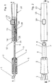
- FIGS. 1 and 2 show a first first embodiment of the handle mounting coupling between a work implement 1 only broken away and a handle, which show the basic idea of the invention schematically
- the implement 1 is connected via a handle 2 with a Traininginsteckzapfen 3, which is in a guide channel 14 of a guide piece 12 can be inserted.
- the guide piece 12 is inserted into the working device adjacent end 11 of a handle tube 10 and secured therein.
- first curved leaf spring 18 which has a protruding into the guide channel 14 locking element 20, which is inserted in device Einsteckzapfen 3 in arranged at the free end of the locking opening 6 engages and thus locks the Adjustinsteckzapfen 3 in the guide piece 12 in the axial direction.
- An unlocking is possible by operating a control knob 19 which is depressibly arranged in a guide bore 17 above the free end of the leaf spring 18.
- a compensation sleeve 4 is preferably arranged on the hand FIGS. 17 to 19 is described in more detail and is used to compensate for axial play between the device and stem.
- the rectangular cross section of the device plug is merely an example; Other cross-sectional shapes could also be used with a corresponding design of the guide channel, wherein the recesses 7 for the or the pressure cams are adapted accordingly.
- the one or more pressure cams 15 can also fulfill another important function. In accidental accidental operation of the control knob, the device insertion pin is still held by the pressure cam. The device will not, for example, in a hacking, in an unintentional and possibly bystanders endangering manner of the stem solve.
- the desired height of the safety holding force can be adjusted via the pressure force of the cam, so the design of the other leaf spring or the elastic element and the shape of the recesses in the device insertion pin.
- each pressure cam 7 are shown, which engage the sides of the device insertion pin 3.
- additional pressure cams above and below the Artificialinsteckzapfens 3 may be arranged to further reduce the radial clearance of the free rear end of the Artificialinsteckzapfens 3.
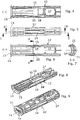
- FIGS. 4 to 9 An embodiment of the guide piece integrally formed with this guide piece pressure cam 15 and the associated, this pressure cam in the radial direction inwardly biasing further flat spring 18 is from the FIGS. 4 to 9 seen.
- the further flat springs 18 and the pressure cams are integrally formed with the guide piece 12 in the form of a plastic injection molded part, which is then inserted into the free end of the stem tube 10 to the limit by a circumferential flange 21, which at the outer end of the guide piece 12 is arranged.
- this guide piece may be formed to simplify the production of two halves, which are held together after insertion into the stem tube.
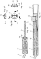
- FIGS. 10 to 12 show in conjunction with the FIGS. 10a to 12a two embodiments of the device insertion pin 3.
- the in FIG. 10 and 10a shown massive embodiment 31 is used for larger devices.
- a sheet-metal shaped part 32 is used, which can be stiffened by indentations 33.
- Both embodiments have the above-mentioned recesses 6, 7 in the same position and in the same size, so that they can be used with the same stems.
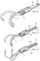
- FIGS. 17 to 19 show an embodiment of an elastic compensation sleeve 41, which is arranged between the outer end of the guide piece 12 and the handle 2.
- the cuff 41 is curved and due to their shape able to ensure a balance of axial play between the device and stem despite the long tolerance chain, as can be seen from a comparison of FIGS. 15 and 16 to recognize ..
- the collar has at its end facing the handle locking means for attachment to the end of the handle 2 and at the end facing the guide piece a conical projection 43 which is insertable into the conical opening 13 of the guide piece.
- the Actinsteckzapfen 3 extends through an opening 42 in this sleeve.
- FIG. 15 This cuff 41 is shown prior to insertion into the guide piece 12, while in FIG. 16 the deformation of the sleeve at the end of insertion into the guide piece 12 can be seen, which eliminates any radial and axial play at the free outer end of the guide piece 12.
Abstract
Eine Stielbefestigungskupplung, insbesondere für Haus- und Gartengeräte, mit einem in ein Stielrohr-Ende eingepressten Führungsstück (12), das einen langestreckten Führungskanal (14) für einen Geräteeinsteckzapfen (3) aufweist, der ein an dem Gerät befestigtes erstes Ende und ein zweites freies Ende aufweist, wobei das zweite Ende eine Verriegelungsöffnung (6) aufweist, und mit einem Riegelelement (20), das durch eine Rastfeder (18) in einer ersten Radialrichtung quer zur Stielachse vorgespannt und zum Einrasten in die Verriegelungsöffnung des Geräteeinsteckzapfens ausgebildet ist, wobei das Riegelelement durch einen Bedienknopf in Radialrichtung aus der Verriegelungsöffnung heraus bewegbar ist, um den Geräteeinsteckzapfen (3) zum Herausziehen aus dem Führungskanal freizugeben, ist dadurch gekennzeichnet, dass benachbart zu der Verriegelungsöffnung (6) in dem Führungskanal (14) des Führungsstückes (12) zumindest ein elastisch in Radialrichtung nach innen vorgespannter Drucknocken (7) angeordnet ist, der zur Ausübung von Radialkräften unter einem Winkel zur ersten Radialrichtung auf einen in den Führungskanal (14) eingesteckten Geräteeinsteckzapfen (3) ausgebildet ist.A handle mounting coupling, in particular for home and garden tools, having a guide piece (12) pressed into a handle end having an elongate guide channel (14) for a device insertion pin (3) having a first end attached to the device and a second free end End having the second end having a locking opening (6), and with a locking element (20) biased by a detent spring (18) in a first radial direction transverse to the stem axis and adapted to engage in the locking hole of the Geräteinzzapfens, wherein the Locking element by a control knob in the radial direction out of the locking hole is movable to release the Geräteinsteckzapfen (3) for pulling out of the guide channel, characterized in that adjacent to the locking opening (6) in the guide channel (14) of the guide piece (12) at least an elastically biased inward in the radial direction Pressure cam (7) is arranged, which is designed for the application of radial forces at an angle to the first radial direction on an inserted into the guide channel (14) Geräteinsteckzapfen (3).
Description
Im Bereich der Gartengeräte haben sich lösbare Stielbefestigungskupplungen durchgesetzt. Damit sind verschiedene Vorteile für den Anwender verbunden: Die Geräte können mit den verschiedenen Stiellängen kombiniert werden. Es muss nicht für jedes Gerät ein Stiel gekauft werden. Insbesondere teure ausziehbare Stiele können für verschiedene Geräte wie Schere oder Säge genutzt werden. Das spart Geld und verringert den erforderlichen Lagerraum. Generell kann bei diesen lösbaren Stielbefestigungskupplungen zwischen den kraftschlüssigen und den formschlüssigen Grundtypen unterschieden werden.In the field of garden tools detachable handle attachment couplings have prevailed. There are several advantages for the user: The devices can be combined with the different stem lengths. There is no need to buy a stalk for each device. In particular, expensive extendable stems can be used for various devices such as scissors or saw. This saves money and reduces the required storage space. Generally can be distinguished in these releasable handle mounting couplings between the non-positive and the positive basic types.
Eine formschlüssige Verbindung zwischen einem Gartengerät und einem Gerätestiel ist beispielweise aus der
Demgegenüber wirken kraftschlüssige Verbindungen, beispielsweise durch Festlegen des Einsteckzapfens in einer Führungsbohrung des Führungsstückes durch eine Schraube, spielfrei. Diese Stielbefestigungskupplung ist jedoch in der Anwendung zeitaufwändig und umständlich.In contrast, frictional connections, for example by setting the Einsteckzapfens in a guide bore of the guide piece by a screw, play free of play. However, this handle mounting coupling is time consuming and cumbersome to use.
Der Erfindung liegt also die Aufgabe zu Grunde, die Vorteile der formschlüssigen Verbindung durch einen geeigneten Toleranzausgleich zu ergänzen, der die Bedienung nicht erschwert, aber dennoch das Spiel derart ausgleicht, dass es nicht mehr negativ in Erscheinung tritt. Ferner soll die Sicherheit der Stielbefestigungskupplung bei zufälliger Betätigung des Bedienknopfes erhöht werden.The invention is therefore based on the object to supplement the advantages of the positive connection by a suitable tolerance compensation, which does not complicate the operation, but still compensates the game so that it no longer appears negative in appearance. Furthermore, the safety of the handle mounting coupling should be increased by accidental operation of the control knob.
Die Aufgabe wird erfindungsgemäß durch die Merkmale des Anspruchs 1 gelöst. Vorteilhafte Ausgestaltungen und Weiterbildungen der Erfindung ergeben sich aus den Unteansprüchen.The object is achieved by the features of
Bei der erfindungsgemäßen Stielbefestigungskupplung ist in dem Führungsstück mindestens eine weitere Blattfeder oder ein anderes elastisches Element integriert, die bzw. das spielausgleichend insbesondere auf das freie Ende des Geräteeinsteckzapfens wirkt.In the handle attachment coupling according to the invention, at least one further leaf spring or another elastic element is integrated in the guide piece, which acts in a play compensating manner, in particular on the free end of the device insertion pin.
Dies wird mittels gemäß einer Ausführungsform durch einen Drucknocken erreicht, der unter Spannung in eine Ausnehmung in der Seitenfläche des vorzugsweise einen rechteckigen Querschnitt aufweisenden Geräteeinsteckzapfens eingreift und den Geräteeinsteckzapfen festklemmt. Auf diese Weise wird das fühlbare Spiel eliminiert.This is achieved by means of an embodiment by a pressure cam, which engages under tension in a recess in the side surface of the preferably having a rectangular cross-section device Einsteckzapfens and clamps the Geräteinsteckzapfen. In this way, the tactile game is eliminated.
Der Drucknocken kann auch eine weitere wichtige Funktion. Bei zufälliger unbeabsichtigter Betätigung des Bedienknopfes, wird der Geräteeinsteckzapfen immer noch von dem Drucknocken gehalten. Das Gerät wird sich also nicht, etwa bei einer Hackbewegung, in ungewollter und eventuell Umstehende gefährdenden Art und Weise von dem Stiel lösen.The pressure cam can also have another important function. In accidental accidental operation of the control knob, the device insertion pin is still held by the pressure cam. The device will not, for example, in a hacking, in an unintentional and possibly bystanders endangering manner of the stem solve.
Die gewünschte Höhe der Sicherheitshaltekraft kann über die Druckkraft des Nockens, also die Gestaltung der weiteren Blattfeder oder des elastischen Elementes und die Form der Ausnehmungen in dem Geräteeinsteckzapfen eingestellt werden.The desired height of the safety holding force can be adjusted via the pressure force of the cam, so the design of the other leaf spring or the elastic element and the shape of the recesses in the device insertion pin.
Die Erfindung wird im Folgenden anhand von in der Zeichnung dargestellten Ausführungsbeispielen noch näher erläutert.The invention will be explained in more detail below with reference to embodiments shown in the drawing.
In der Zeichnung zeigen:
-
Figur 1Figur 2 -
Figur 2Figur 1 -
Figur 3 -
Figur 4Figur 5 -
Figur 5 -
Figur 6Figur 5Figur 5 -
Figur 7Figur 6 -
Figur 8 eine perspektivische Darstellung des Führungsstückes in derDarstellung nach Figur 4 ; -
Figur 9 eine perspektivische Ansicht einer Ausführungsform des Führungsstückes nachden Figuren 4 ;bis 7 -
Figur 10 -
Figur 11 -
Figur 12Figur 11 bei Betrachtung von unten; -
Figuren 10a bis 12a den Figuren 10 entsprechende getrennte Darstellungen des Geräteeinsteckzapfens;bis 12 -
Figur 13 -
Figur 14Figur 13 um 90° gedrehten Schnittansicht des Stiels und des Geräteeinsteckzapfens; -
Figur 15 -
Figur 16 -
Figur 17nach den Figuren 15 ;und 17 -
Figur 18 -
Figur 19Figur 18 .
-
FIG. 1 a sectional side view of an embodiment of the handle mounting coupling when viewed along the section line AA inFIG. 2 ; -
FIG. 2 a plan view of the embodiment of the handle mounting coupling afterFIG. 1 ; -
FIG. 3 a further sectional view taken along the line AA when looking at the embodiment of the handle mounting coupling from above; -
FIG. 4 a sectional view of an embodiment of the guide section along the section line CC afterFIG. 5 ; -
FIG. 5 an external view of the guide piece of the handle mounting coupling; -
FIG. 6 one opposite theFIG. 5 rotated by 90 ° shown sectional view along the line AA toFIG. 5 ; -
FIG. 7 a sectional view taken along the line BBFIG. 6 ; -
FIG. 8 a perspective view of the guide piece in the illustrationFIG. 4 ; -
FIG. 9 a perspective view of an embodiment of the guide piece after theFIGS. 4 to 7 ; -
FIG. 10 a perspective view of a first embodiment of a device with a first embodiment of the device insertion pin; -
FIG. 11 a perspective view of a second embodiment of a device with a second embodiment of the Geräteinzzzffens viewed from above; -
FIG. 12 a perspective view of the second embodiment of the Geräteinzzapfen afterFIG. 11 when viewed from below; -
FIGS. 10a to 12a theFIGS. 10 to 12 corresponding separate representations of the device insertion pin; -
FIG. 13 a vertical sectional view through the free end of the stem and the guide piece with plugged device Einsteckzapfens; -
FIG. 14 a partial sectional view in one oppositeFIG. 13 rotated 90 ° sectional view of the stem and the device insertion pin; -
FIG. 15 a further embodiment of a handle of the device and the Einsteckzapfens; -
FIG. 16 a vertical sectional view of the handle and the Geräteinsteckzapfens in the inserted state in the guide piece; -
FIG. 17 a partial view of the compensating cuff according to the embodiments of theFIGS. 15 and 17 ; -
FIG. 18 a top view of the compensation cuff; -
FIG. 19 a section along the line BB afterFIG. 18 ,
Die
Das Arbeitsgerät 1 ist über ein Griffstück 2 mit einem Geräteeinsteckzapfen 3 verbunden, der in einen Führungskanal 14 eines Führungsstückes 12 einsteckbar ist. Das Führungstück 12 ist in das dem Arbeitsgerät benachbarte Ende 11 eines Stielrohres 10 eingesetzt und in diesem befestigt.The implement 1 is connected via a
In dem Führungsstück 12 oder zwischen diesem und der Innenwand des Endes 11 dies Stielrohres 10 ist eine in Richtung auf die Mitte des Endes 11 vorgespannte erste gebogenen Blattfeder 18 festgelegt, die ein in den Führungskanal 14 vorspringendes Rastelement 20 aufweist, das bei eingestecktem Geräteeinsteckzapfen 3 in eine an dessen freiem Ende angeordnete Verriegelungsöffnung 6 eingreift und damit den Geräteeinsteckzapfen 3 in dem Führungsstück 12 in Axialrichtung verriegelt. Eine Entriegelung ist durch Betätigung eines Bedienknopfes 19 möglich, der in einer Führungsbohrung 17 oberhalb des freien Endes der Blattfeder 18 niederdrückbar angeordnet ist.In the
Zwischen dem Griffstück 2 und dem äußeren Ende des Führungsstückes 12 ist vorzugsweise eine Ausgleichsmanschette 4 angeordnet, die an Hand der
Hierbei verbleibt jedoch noch das Problem eines radialen Spiels, insbesondere am freien Ende des Geräteeinsteckzapfens.However, this still leaves the problem of a radial clearance, especially at the free end of the device insertion pin.
Dieses radiale Spiel wird gemäß einer vorteilhaften Ausführungsform durch mindestens einen Drucknocken 15 beseitigt, der unter elastischer Vorspannung in eine oder mehrere Ausnehmungen 7 in der Seitenfläche des vorzugsweise einen rechteckigen Querschnitt aufweisenden Geräteeinsteckzapfens 3 eingreift und diesen festklemmt, wie dies inbesondere aus den
Auf diese Weise wird das fühlbare Spiel eliminiert.In this way, the tactile game is eliminated.
Der rechteckige Querschnitt des Geräteeinsteckzapfens stellt lediglich ein Beispiel dar; es könnten auch andere Querschnittsformen bei entsprechender Ausgestaltung des Führungskanals verwendet werden, wobei die Ausnehmungen 7 für den oder die Drucknocken entsprechend anzupassen sind.The rectangular cross section of the device plug is merely an example; Other cross-sectional shapes could also be used with a corresponding design of the guide channel, wherein the
Der oder die Drucknocken 15 können auch eine weitere wichtige Funktion erfüllen. Bei zufälliger unbeabsichtigter Betätigung des Bedienknopfes, wird der Geräteeinsteckzapfen immer noch von dem Drucknocken gehalten. Das Gerät wird sich also nicht, etwa bei einer Hackbewegung, in ungewollter und eventuell Umstehende gefährdenden Art und Weise von dem Stiel lösen.The one or
Die gewünschte Höhe der Sicherheitshaltekraft kann über die Druckkraft des Nockens, also die Gestaltung der weiteren Blattfeder oder des elastischen Elementes und die Form der Ausnehmungen in dem Geräteeinsteckzapfen eingestellt werden.The desired height of the safety holding force can be adjusted via the pressure force of the cam, so the design of the other leaf spring or the elastic element and the shape of the recesses in the device insertion pin.
In den Zeichnungen sind jeweils Drucknocken 7 gezeigt, die an den Seiten des Geräteeinsteckzapfens 3 angreifen. In gleicher Weise könnten beispielsweise bei der in
Eine Ausführungsform des Führungsstückes mit einstückig mit diesem Führungsstück ausgebildeten Drucknocken 15 und der zugehörigen, diese Drucknocken in Radialrichtung nach innen vorspannenden weiteren Flachfeder 18 ist aus den
Wie dies insbesondere aus den
In gleicher Weise ist es möglich, die weiteren Flachfedern und die Drucknocken als getrenntes Bauteil auszuführen, die in einer entsprechenden umlaufenden Ausnehmung des Führungsstückes 12 dieses Führungsstück umgreifend angeordnet sind.In the same way, it is possible to perform the other flat springs and the pressure cams as a separate component, which are arranged encompassing in a corresponding circumferential recess of the
Die
Die
Die Manschette weist an ihrem dem Griffstück zugewandten Ende Rasteinrichtungen zur Befestigung an dem Ende des Griffstückes 2 und an dem den Führungsstück zugewandten Ende einen konischen Ansatz 43 auf, der in die konische Öffnung 13 des Führungsstückes einsetzbar ist. Der Geräteeinsteckzapfen 3 erstreckt sich durch eine Öffnung 42 in dieser Manschette.The collar has at its end facing the handle locking means for attachment to the end of the
In
Im Zusammenwirken mit dem Drucknocken ergibt sich damit eine sehr sichere Halterung des Geräteeinsteckzapfens 3 in dem Führungsstück 12 beziehungsweise dem Ende des Stielrohres 10.In cooperation with the pressure cam, this results in a very secure mounting of the
Claims (17)
Applications Claiming Priority (1)
| Application Number | Priority Date | Filing Date | Title |
|---|---|---|---|
| DE102016012586.1A DE102016012586B4 (en) | 2016-10-21 | 2016-10-21 | Detachable handle attachment coupling for tools |
Publications (2)
| Publication Number | Publication Date |
|---|---|
| EP3318368A1 true EP3318368A1 (en) | 2018-05-09 |
| EP3318368B1 EP3318368B1 (en) | 2023-08-23 |
Family
ID=60143465
Family Applications (1)
| Application Number | Title | Priority Date | Filing Date |
|---|---|---|---|
| EP17001716.4A Active EP3318368B1 (en) | 2016-10-21 | 2017-10-17 | Releasable handle fixing coupling for working units |
Country Status (4)
| Country | Link |
|---|---|
| US (1) | US11401964B2 (en) |
| EP (1) | EP3318368B1 (en) |
| CA (1) | CA2983331A1 (en) |
| DE (1) | DE102016012586B4 (en) |
Cited By (1)
| Publication number | Priority date | Publication date | Assignee | Title |
|---|---|---|---|---|
| US10807261B2 (en) | 2017-06-21 | 2020-10-20 | Harry's, Inc. | Razor handle |
Families Citing this family (3)
| Publication number | Priority date | Publication date | Assignee | Title |
|---|---|---|---|---|
| US10688649B1 (en) * | 2017-02-14 | 2020-06-23 | Martinez Tool Company, Inc. | Implement handle grip having an improved handle engaging mechanism |
| US11523815B2 (en) * | 2019-06-13 | 2022-12-13 | Smith & Nephew, Inc. | Side-loading knot cutter |
| BE1029759B1 (en) * | 2021-09-16 | 2023-04-11 | Polet Quality Products | ONE PIECE OF TOOLS |
Citations (3)
| Publication number | Priority date | Publication date | Assignee | Title |
|---|---|---|---|---|
| DE3246887A1 (en) | 1982-02-04 | 1983-08-18 | Wolf-Geräte GmbH, 5240 Betzdorf | Handle-fastening coupling, in particular for household and garden implements |
| WO2003057419A1 (en) * | 2002-01-11 | 2003-07-17 | Johannes Engl | Floor cleaning device |
| US8844942B1 (en) * | 2010-06-25 | 2014-09-30 | Greatbatch Ltd. | Quick-load connector for a surgical tool |
Family Cites Families (23)
| Publication number | Priority date | Publication date | Assignee | Title |
|---|---|---|---|---|
| US825976A (en) * | 1905-12-11 | 1906-07-17 | Anders E Neiglick | Knife. |
| US3774252A (en) * | 1972-03-22 | 1973-11-27 | J Cantales | Spackling knife tool |
| EP0057916B1 (en) * | 1981-02-06 | 1985-06-19 | Wolf-Geräte GmbH | Device for attaching handles to utensils, in particular household utensils and garden tools |
| DE3143080C2 (en) * | 1981-10-30 | 1983-09-29 | Fa. Carl Freudenberg, 6940 Weinheim | Handle attachment, especially for brooms |
| DE3519544A1 (en) * | 1985-05-31 | 1986-12-04 | Rux GmbH, 3013 Barsinghausen | Device for the rapid exchange in particular of garden implements on a handle |
| US4870757A (en) * | 1988-07-05 | 1989-10-03 | Kirkpatrick Hugh J | Drywall Cutting tool |
| US5535484A (en) * | 1993-10-05 | 1996-07-16 | Gibson; Jeremy H. | Utensil handle |
| US5477758A (en) * | 1994-09-19 | 1995-12-26 | Cunningham; Jerry L. | Automotive flywheel and belt tension tool kit |
| US6055733A (en) * | 1999-05-03 | 2000-05-02 | Chen; Yih-Long | Extensible cutlery device |
| US6370990B1 (en) * | 2000-02-24 | 2002-04-16 | Chuck (Chen-Tsai) Chang | Handle structure for adjusting the arm of force of a tool |
| DE20018803U1 (en) * | 2000-11-03 | 2001-01-11 | Chen Kun You | Scraper iron with a practical fastener of a handle |
| DE10225056A1 (en) * | 2002-06-06 | 2003-12-18 | Proxxon Sa | tool handle |
| DE102005048867A1 (en) * | 2005-10-12 | 2007-04-19 | Wolf-Garten Ag | handle mounting |
| US7625033B2 (en) * | 2006-01-30 | 2009-12-01 | Radio Flyer, Inc. | Accessory latching assembly |
| US7805843B2 (en) * | 2006-09-15 | 2010-10-05 | Bel-Art Products, Inc. | Eating utensil |
| US8856995B2 (en) * | 2006-12-01 | 2014-10-14 | A. Richard Tools Co./Outils A. Richard Co. | Screw bit putty knife |
| US8096213B2 (en) * | 2007-11-16 | 2012-01-17 | Neil Miers | Utility insert tool with spherical retaining ball member and torsion bar for securing detachable utility inserts |
| US20100192738A1 (en) * | 2008-10-02 | 2010-08-05 | Fenstemaker Daniel P | Tool with interchangeable work heads |
| DE102009005814B4 (en) * | 2009-01-22 | 2013-02-28 | Jin-Tsai Lai | Detachable handle |
| FR2975033B1 (en) * | 2011-05-13 | 2015-04-24 | Castorama France | HAND TOOL EQUIPPED WITH A DEVICE FOR FASTENING AT LEAST ONE TOOL HEAD AT THE END OF AT LEAST ONE HANDLE |
| EP2946889A1 (en) * | 2014-05-19 | 2015-11-25 | SLS Powerinvest BVBA | A connector assembly for connecting a domestic implement to a handle |
| US10478949B2 (en) * | 2016-01-15 | 2019-11-19 | II John Terrel White | Wrench assemblies |
| US20180178369A1 (en) * | 2016-12-28 | 2018-06-28 | Shou-Hung Chen | Hand tool assembly |
-
2016
- 2016-10-21 DE DE102016012586.1A patent/DE102016012586B4/en active Active
-
2017
- 2017-10-17 EP EP17001716.4A patent/EP3318368B1/en active Active
- 2017-10-23 CA CA2983331A patent/CA2983331A1/en not_active Abandoned
- 2017-10-23 US US15/790,646 patent/US11401964B2/en active Active
Patent Citations (3)
| Publication number | Priority date | Publication date | Assignee | Title |
|---|---|---|---|---|
| DE3246887A1 (en) | 1982-02-04 | 1983-08-18 | Wolf-Geräte GmbH, 5240 Betzdorf | Handle-fastening coupling, in particular for household and garden implements |
| WO2003057419A1 (en) * | 2002-01-11 | 2003-07-17 | Johannes Engl | Floor cleaning device |
| US8844942B1 (en) * | 2010-06-25 | 2014-09-30 | Greatbatch Ltd. | Quick-load connector for a surgical tool |
Cited By (1)
| Publication number | Priority date | Publication date | Assignee | Title |
|---|---|---|---|---|
| US10807261B2 (en) | 2017-06-21 | 2020-10-20 | Harry's, Inc. | Razor handle |
Also Published As
| Publication number | Publication date |
|---|---|
| EP3318368B1 (en) | 2023-08-23 |
| CA2983331A1 (en) | 2018-04-21 |
| US11401964B2 (en) | 2022-08-02 |
| DE102016012586B4 (en) | 2020-02-06 |
| DE102016012586A1 (en) | 2018-04-26 |
| US20180112700A1 (en) | 2018-04-26 |
Similar Documents
| Publication | Publication Date | Title |
|---|---|---|
| EP3318368A1 (en) | Releasable handle fixing coupling for working units | |
| EP1969280B1 (en) | Plug-in part for a plug connector arrangement | |
| EP1166003A1 (en) | Coupling part for a fluid coupling device, especially a hose coupling, as well as a fluid coupling device itself | |
| DE10358683A1 (en) | Device for connecting a carrier part and an attachment | |
| DE102007022186A1 (en) | Adapter for operating a hole saw on a drive machine | |
| DE102007005033A1 (en) | Tool holder for a machine tool, in particular for a hand tool | |
| EP1746244A2 (en) | Closure device for openings in buildings | |
| DE102008059827B4 (en) | Sliding shoe for a switching element of a switching device and switching element with such a sliding shoe | |
| DE102020108073A1 (en) | Connector with pre-assembly lock | |
| DE19941794B4 (en) | Arrangement of a pressure piece in a synchronizer | |
| EP0280180B1 (en) | Detachable plug-in connection for pipes | |
| DE102018128203A1 (en) | Electrical connector part and electrical connector system with lock | |
| EP3742561A1 (en) | Electric plug connector | |
| DE202013105249U1 (en) | Electromotive linear drive | |
| DE202016101842U1 (en) | Connection adapter with the possibility for fast connection with different tools | |
| DE102013106496B3 (en) | Segmented device handle with stem tube connection | |
| DE102006007244A1 (en) | Fastening element has thread section extending along longitudinal axis, which is provided with inside or outside thread, and flange section that has support surface for supporting one of components | |
| DE3246042C2 (en) | Connection device for producing a detachable plug connection | |
| DE202012101417U1 (en) | Schnellwechselbithalter | |
| EP3884197A1 (en) | Coupling | |
| DE102004011579B4 (en) | Chuck for tool inserts | |
| DE102013107469B3 (en) | extension rod | |
| DE10324581B3 (en) | Spreading rivet for fixing components to each other has setting device to enable manual to be withdrawn to initial position after fitting | |
| EP2394088A1 (en) | Connecting device for a guide element and connecting system | |
| DE202015100593U1 (en) | F-shaped hand tool |
Legal Events
| Date | Code | Title | Description |
|---|---|---|---|
| PUAI | Public reference made under article 153(3) epc to a published international application that has entered the european phase |
Free format text: ORIGINAL CODE: 0009012 |
|
| STAA | Information on the status of an ep patent application or granted ep patent |
Free format text: STATUS: THE APPLICATION HAS BEEN PUBLISHED |
|
| AK | Designated contracting states |
Kind code of ref document: A1 Designated state(s): AL AT BE BG CH CY CZ DE DK EE ES FI FR GB GR HR HU IE IS IT LI LT LU LV MC MK MT NL NO PL PT RO RS SE SI SK SM TR |
|
| AX | Request for extension of the european patent |
Extension state: BA ME |
|
| STAA | Information on the status of an ep patent application or granted ep patent |
Free format text: STATUS: REQUEST FOR EXAMINATION WAS MADE |
|
| 17P | Request for examination filed |
Effective date: 20180704 |
|
| RBV | Designated contracting states (corrected) |
Designated state(s): AL AT BE BG CH CY CZ DE DK EE ES FI FR GB GR HR HU IE IS IT LI LT LU LV MC MK MT NL NO PL PT RO RS SE SI SK SM TR |
|
| 19U | Interruption of proceedings before grant |
Effective date: 20190418 |
|
| 19W | Proceedings resumed before grant after interruption of proceedings |
Effective date: 20191202 |
|
| STAA | Information on the status of an ep patent application or granted ep patent |
Free format text: STATUS: EXAMINATION IS IN PROGRESS |
|
| 17Q | First examination report despatched |
Effective date: 20210421 |
|
| STAA | Information on the status of an ep patent application or granted ep patent |
Free format text: STATUS: EXAMINATION IS IN PROGRESS |
|
| GRAP | Despatch of communication of intention to grant a patent |
Free format text: ORIGINAL CODE: EPIDOSNIGR1 |
|
| STAA | Information on the status of an ep patent application or granted ep patent |
Free format text: STATUS: GRANT OF PATENT IS INTENDED |
|
| RAP3 | Party data changed (applicant data changed or rights of an application transferred) |
Owner name: MTD PRODUCTS INC. |
|
| RIN1 | Information on inventor provided before grant (corrected) |
Inventor name: SCHMIDT, PATRICK CHRISTIAN Inventor name: HELD, PETER |
|
| INTG | Intention to grant announced |
Effective date: 20230306 |
|
| GRAS | Grant fee paid |
Free format text: ORIGINAL CODE: EPIDOSNIGR3 |
|
| GRAA | (expected) grant |
Free format text: ORIGINAL CODE: 0009210 |
|
| STAA | Information on the status of an ep patent application or granted ep patent |
Free format text: STATUS: THE PATENT HAS BEEN GRANTED |
|
| AK | Designated contracting states |
Kind code of ref document: B1 Designated state(s): AL AT BE BG CH CY CZ DE DK EE ES FI FR GB GR HR HU IE IS IT LI LT LU LV MC MK MT NL NO PL PT RO RS SE SI SK SM TR |
|
| REG | Reference to a national code |
Ref country code: GB Ref legal event code: FG4D Free format text: NOT ENGLISH |
|
| REG | Reference to a national code |
Ref country code: CH Ref legal event code: EP |
|
| REG | Reference to a national code |
Ref country code: DE Ref legal event code: R096 Ref document number: 502017015248 Country of ref document: DE |
|
| REG | Reference to a national code |
Ref country code: IE Ref legal event code: FG4D Free format text: LANGUAGE OF EP DOCUMENT: GERMAN |
|
| P01 | Opt-out of the competence of the unified patent court (upc) registered |
Effective date: 20230828 |
|
| PGFP | Annual fee paid to national office [announced via postgrant information from national office to epo] |
Ref country code: GB Payment date: 20230824 Year of fee payment: 7 |
|
| PGFP | Annual fee paid to national office [announced via postgrant information from national office to epo] |
Ref country code: FR Payment date: 20230821 Year of fee payment: 7 |
|
| REG | Reference to a national code |
Ref country code: LT Ref legal event code: MG9D |
|
| REG | Reference to a national code |
Ref country code: NL Ref legal event code: MP Effective date: 20230823 |
|
| PG25 | Lapsed in a contracting state [announced via postgrant information from national office to epo] |
Ref country code: GR Free format text: LAPSE BECAUSE OF FAILURE TO SUBMIT A TRANSLATION OF THE DESCRIPTION OR TO PAY THE FEE WITHIN THE PRESCRIBED TIME-LIMIT Effective date: 20231124 |
|
| PG25 | Lapsed in a contracting state [announced via postgrant information from national office to epo] |
Ref country code: IS Free format text: LAPSE BECAUSE OF FAILURE TO SUBMIT A TRANSLATION OF THE DESCRIPTION OR TO PAY THE FEE WITHIN THE PRESCRIBED TIME-LIMIT Effective date: 20231223 |
|
| PG25 | Lapsed in a contracting state [announced via postgrant information from national office to epo] |
Ref country code: SE Free format text: LAPSE BECAUSE OF FAILURE TO SUBMIT A TRANSLATION OF THE DESCRIPTION OR TO PAY THE FEE WITHIN THE PRESCRIBED TIME-LIMIT Effective date: 20230823 Ref country code: RS Free format text: LAPSE BECAUSE OF FAILURE TO SUBMIT A TRANSLATION OF THE DESCRIPTION OR TO PAY THE FEE WITHIN THE PRESCRIBED TIME-LIMIT Effective date: 20230823 Ref country code: PT Free format text: LAPSE BECAUSE OF FAILURE TO SUBMIT A TRANSLATION OF THE DESCRIPTION OR TO PAY THE FEE WITHIN THE PRESCRIBED TIME-LIMIT Effective date: 20231226 Ref country code: NO Free format text: LAPSE BECAUSE OF FAILURE TO SUBMIT A TRANSLATION OF THE DESCRIPTION OR TO PAY THE FEE WITHIN THE PRESCRIBED TIME-LIMIT Effective date: 20231123 Ref country code: NL Free format text: LAPSE BECAUSE OF FAILURE TO SUBMIT A TRANSLATION OF THE DESCRIPTION OR TO PAY THE FEE WITHIN THE PRESCRIBED TIME-LIMIT Effective date: 20230823 Ref country code: LV Free format text: LAPSE BECAUSE OF FAILURE TO SUBMIT A TRANSLATION OF THE DESCRIPTION OR TO PAY THE FEE WITHIN THE PRESCRIBED TIME-LIMIT Effective date: 20230823 Ref country code: LT Free format text: LAPSE BECAUSE OF FAILURE TO SUBMIT A TRANSLATION OF THE DESCRIPTION OR TO PAY THE FEE WITHIN THE PRESCRIBED TIME-LIMIT Effective date: 20230823 Ref country code: IS Free format text: LAPSE BECAUSE OF FAILURE TO SUBMIT A TRANSLATION OF THE DESCRIPTION OR TO PAY THE FEE WITHIN THE PRESCRIBED TIME-LIMIT Effective date: 20231223 Ref country code: HR Free format text: LAPSE BECAUSE OF FAILURE TO SUBMIT A TRANSLATION OF THE DESCRIPTION OR TO PAY THE FEE WITHIN THE PRESCRIBED TIME-LIMIT Effective date: 20230823 Ref country code: GR Free format text: LAPSE BECAUSE OF FAILURE TO SUBMIT A TRANSLATION OF THE DESCRIPTION OR TO PAY THE FEE WITHIN THE PRESCRIBED TIME-LIMIT Effective date: 20231124 Ref country code: FI Free format text: LAPSE BECAUSE OF FAILURE TO SUBMIT A TRANSLATION OF THE DESCRIPTION OR TO PAY THE FEE WITHIN THE PRESCRIBED TIME-LIMIT Effective date: 20230823 |
|
| PGFP | Annual fee paid to national office [announced via postgrant information from national office to epo] |
Ref country code: DE Payment date: 20230822 Year of fee payment: 7 |
|
| PG25 | Lapsed in a contracting state [announced via postgrant information from national office to epo] |
Ref country code: PL Free format text: LAPSE BECAUSE OF FAILURE TO SUBMIT A TRANSLATION OF THE DESCRIPTION OR TO PAY THE FEE WITHIN THE PRESCRIBED TIME-LIMIT Effective date: 20230823 |
|
| PG25 | Lapsed in a contracting state [announced via postgrant information from national office to epo] |
Ref country code: ES Free format text: LAPSE BECAUSE OF FAILURE TO SUBMIT A TRANSLATION OF THE DESCRIPTION OR TO PAY THE FEE WITHIN THE PRESCRIBED TIME-LIMIT Effective date: 20230823 |
|
| PG25 | Lapsed in a contracting state [announced via postgrant information from national office to epo] |
Ref country code: SM Free format text: LAPSE BECAUSE OF FAILURE TO SUBMIT A TRANSLATION OF THE DESCRIPTION OR TO PAY THE FEE WITHIN THE PRESCRIBED TIME-LIMIT Effective date: 20230823 Ref country code: RO Free format text: LAPSE BECAUSE OF FAILURE TO SUBMIT A TRANSLATION OF THE DESCRIPTION OR TO PAY THE FEE WITHIN THE PRESCRIBED TIME-LIMIT Effective date: 20230823 Ref country code: ES Free format text: LAPSE BECAUSE OF FAILURE TO SUBMIT A TRANSLATION OF THE DESCRIPTION OR TO PAY THE FEE WITHIN THE PRESCRIBED TIME-LIMIT Effective date: 20230823 Ref country code: EE Free format text: LAPSE BECAUSE OF FAILURE TO SUBMIT A TRANSLATION OF THE DESCRIPTION OR TO PAY THE FEE WITHIN THE PRESCRIBED TIME-LIMIT Effective date: 20230823 Ref country code: DK Free format text: LAPSE BECAUSE OF FAILURE TO SUBMIT A TRANSLATION OF THE DESCRIPTION OR TO PAY THE FEE WITHIN THE PRESCRIBED TIME-LIMIT Effective date: 20230823 Ref country code: CZ Free format text: LAPSE BECAUSE OF FAILURE TO SUBMIT A TRANSLATION OF THE DESCRIPTION OR TO PAY THE FEE WITHIN THE PRESCRIBED TIME-LIMIT Effective date: 20230823 Ref country code: SK Free format text: LAPSE BECAUSE OF FAILURE TO SUBMIT A TRANSLATION OF THE DESCRIPTION OR TO PAY THE FEE WITHIN THE PRESCRIBED TIME-LIMIT Effective date: 20230823 |