EP3318052B1 - Method and apparatus for conversion of hdr signals - Google Patents
Method and apparatus for conversion of hdr signals Download PDFInfo
- Publication number
- EP3318052B1 EP3318052B1 EP16736590.7A EP16736590A EP3318052B1 EP 3318052 B1 EP3318052 B1 EP 3318052B1 EP 16736590 A EP16736590 A EP 16736590A EP 3318052 B1 EP3318052 B1 EP 3318052B1
- Authority
- EP
- European Patent Office
- Prior art keywords
- display
- signal
- values
- scene
- rendering intent
- Prior art date
- Legal status (The legal status is an assumption and is not a legal conclusion. Google has not performed a legal analysis and makes no representation as to the accuracy of the status listed.)
- Active
Links
Images


Classifications
-
- G—PHYSICS
- G06—COMPUTING OR CALCULATING; COUNTING
- G06T—IMAGE DATA PROCESSING OR GENERATION, IN GENERAL
- G06T5/00—Image enhancement or restoration
- G06T5/40—Image enhancement or restoration using histogram techniques
-
- G—PHYSICS
- G09—EDUCATION; CRYPTOGRAPHY; DISPLAY; ADVERTISING; SEALS
- G09G—ARRANGEMENTS OR CIRCUITS FOR CONTROL OF INDICATING DEVICES USING STATIC MEANS TO PRESENT VARIABLE INFORMATION
- G09G5/00—Control arrangements or circuits for visual indicators common to cathode-ray tube indicators and other visual indicators
- G09G5/02—Control arrangements or circuits for visual indicators common to cathode-ray tube indicators and other visual indicators characterised by the way in which colour is displayed
-
- H—ELECTRICITY
- H04—ELECTRIC COMMUNICATION TECHNIQUE
- H04N—PICTORIAL COMMUNICATION, e.g. TELEVISION
- H04N9/00—Details of colour television systems
- H04N9/77—Circuits for processing the brightness signal and the chrominance signal relative to each other, e.g. adjusting the phase of the brightness signal relative to the colour signal, correcting differential gain or differential phase
-
- G—PHYSICS
- G06—COMPUTING OR CALCULATING; COUNTING
- G06T—IMAGE DATA PROCESSING OR GENERATION, IN GENERAL
- G06T5/00—Image enhancement or restoration
- G06T5/90—Dynamic range modification of images or parts thereof
-
- G—PHYSICS
- G06—COMPUTING OR CALCULATING; COUNTING
- G06T—IMAGE DATA PROCESSING OR GENERATION, IN GENERAL
- G06T5/00—Image enhancement or restoration
- G06T5/90—Dynamic range modification of images or parts thereof
- G06T5/92—Dynamic range modification of images or parts thereof based on global image properties
-
- H—ELECTRICITY
- H04—ELECTRIC COMMUNICATION TECHNIQUE
- H04N—PICTORIAL COMMUNICATION, e.g. TELEVISION
- H04N23/00—Cameras or camera modules comprising electronic image sensors; Control thereof
- H04N23/80—Camera processing pipelines; Components thereof
- H04N23/82—Camera processing pipelines; Components thereof for controlling camera response irrespective of the scene brightness, e.g. gamma correction
-
- H—ELECTRICITY
- H04—ELECTRIC COMMUNICATION TECHNIQUE
- H04N—PICTORIAL COMMUNICATION, e.g. TELEVISION
- H04N23/00—Cameras or camera modules comprising electronic image sensors; Control thereof
- H04N23/80—Camera processing pipelines; Components thereof
- H04N23/84—Camera processing pipelines; Components thereof for processing colour signals
- H04N23/86—Camera processing pipelines; Components thereof for processing colour signals for controlling the colour saturation of colour signals, e.g. automatic chroma control circuits
-
- H—ELECTRICITY
- H04—ELECTRIC COMMUNICATION TECHNIQUE
- H04N—PICTORIAL COMMUNICATION, e.g. TELEVISION
- H04N7/00—Television systems
- H04N7/01—Conversion of standards, e.g. involving analogue television standards or digital television standards processed at pixel level
- H04N7/0125—Conversion of standards, e.g. involving analogue television standards or digital television standards processed at pixel level one of the standards being a high definition standard
-
- G—PHYSICS
- G06—COMPUTING OR CALCULATING; COUNTING
- G06T—IMAGE DATA PROCESSING OR GENERATION, IN GENERAL
- G06T2207/00—Indexing scheme for image analysis or image enhancement
- G06T2207/20—Special algorithmic details
- G06T2207/20172—Image enhancement details
- G06T2207/20208—High dynamic range [HDR] image processing
-
- G—PHYSICS
- G09—EDUCATION; CRYPTOGRAPHY; DISPLAY; ADVERTISING; SEALS
- G09G—ARRANGEMENTS OR CIRCUITS FOR CONTROL OF INDICATING DEVICES USING STATIC MEANS TO PRESENT VARIABLE INFORMATION
- G09G2320/00—Control of display operating conditions
- G09G2320/02—Improving the quality of display appearance
- G09G2320/0271—Adjustment of the gradation levels within the range of the gradation scale, e.g. by redistribution or clipping
- G09G2320/0276—Adjustment of the gradation levels within the range of the gradation scale, e.g. by redistribution or clipping for the purpose of adaptation to the characteristics of a display device, i.e. gamma correction
-
- G—PHYSICS
- G09—EDUCATION; CRYPTOGRAPHY; DISPLAY; ADVERTISING; SEALS
- G09G—ARRANGEMENTS OR CIRCUITS FOR CONTROL OF INDICATING DEVICES USING STATIC MEANS TO PRESENT VARIABLE INFORMATION
- G09G2340/00—Aspects of display data processing
- G09G2340/06—Colour space transformation
-
- G—PHYSICS
- G09—EDUCATION; CRYPTOGRAPHY; DISPLAY; ADVERTISING; SEALS
- G09G—ARRANGEMENTS OR CIRCUITS FOR CONTROL OF INDICATING DEVICES USING STATIC MEANS TO PRESENT VARIABLE INFORMATION
- G09G2360/00—Aspects of the architecture of display systems
- G09G2360/16—Calculation or use of calculated indices related to luminance levels in display data
-
- G—PHYSICS
- G09—EDUCATION; CRYPTOGRAPHY; DISPLAY; ADVERTISING; SEALS
- G09G—ARRANGEMENTS OR CIRCUITS FOR CONTROL OF INDICATING DEVICES USING STATIC MEANS TO PRESENT VARIABLE INFORMATION
- G09G2370/00—Aspects of data communication
- G09G2370/04—Exchange of auxiliary data, i.e. other than image data, between monitor and graphics controller
-
- G—PHYSICS
- G09—EDUCATION; CRYPTOGRAPHY; DISPLAY; ADVERTISING; SEALS
- G09G—ARRANGEMENTS OR CIRCUITS FOR CONTROL OF INDICATING DEVICES USING STATIC MEANS TO PRESENT VARIABLE INFORMATION
- G09G5/00—Control arrangements or circuits for visual indicators common to cathode-ray tube indicators and other visual indicators
- G09G5/10—Intensity circuits
Definitions
- This invention relates to processing a video signal from a source, to convert between a signal produced according to first rendering settings to a signal usable by a display of second rendering settings.
- High dynamic range (HDR) video is starting to become available.
- HDR video has a dynamic range, i.e. the ratio between the brightest and darkest parts of the image, of 10000:1 or more.
- Dynamic range is sometimes expressed as "stops" which is logarithm to the base 2 of the dynamic range.
- a dynamic range of 10000:1 therefore equates to 13.29 stops.
- the best modern cameras can capture a dynamic range of 13.5 stops and this is improving as technology develops.
- SDR standard dynamic range
- HDR video provides a subjectively improved viewing experience. It is sometime described as an increased sense of "being there” or alternatively as providing a more “immersive” experience. For this reason many producers of video would like to produce HDR video rather than SDR video. Furthermore since the industry worldwide is moving to HDR video, productions are already being made with high dynamic range, so that they are more likely to retain their value in a future HDR world Document WO 2015/007505 A1 relates to methods for creating code mapping functions for encoding an HDR image. US 2013/076974 A1 and COTTON A ET AL: "BBC's response to CfE for HDR Video Coding (Category 3a)", 112.
- FIG. 1 shows an example system in which a modified OETF may be used to attempt to provide such conversion.
- An OETF is a function defining conversion of a brightness value from a camera to a "voltage" signal value for subsequent processing.
- a power law with exponent 0.5 i.e. square root
- This opto-electronic transfer function is defined in standard ITU Recommendation BT.709 (hereafter "Rec 709”) as:
- V ⁇ 4.5 L for 0 ⁇ L ⁇ 0.018 1.099 L 0.45 ⁇ 0.099 for 0.018 ⁇ L ⁇ 1 where:
- the arrangement shown in Figure 1 comprises an HDR OETF 10 arranged to convert linear light from a scene into RGB signals. This will typically be provided in a camera.
- the RGB signals may be converted to YCbCr signals in a converter 12 for transmission and then converted from YCbCr back to RGB at converters 14 and 16 at a receiver.
- the RGB signals may then be provided to either an HDR display or SDR display. If the receiver is an HDR display then it will display the full dynamic range of the signal using the HDR EOTF 18 to accurately represent the original signal created by the HDR OETF.
- the EOTF 20 within that display is unable to present the full dynamic range and so will necessarily provide some approximation to the appropriate luminance level for the upper luminance values of the signal.
- the way in which a standard dynamic range display approximates an HDR signal depends upon the relationship between the HDR OETF used at the transmitter side and the standard dynamic range EOTF used at the receiver side.
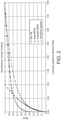
- Figure 2 shows various modifications to OETFs including the OETF of Rec 709 for comparison. These include a known “knee” arrangement favoured by camera makers who modify the OETF by adding a third section near white, by using a "knee", to increase dynamic range and avoid clipping the signal. Also shown is a known “perceptual quantizer” arrangement. Lastly, a proposed arrangement using a curve that includes a power law portion and a log law portion is also shown. The way in which an SDR display using the matched Rec 1886 EOTF represents images produced using one of the HDR OETF depends upon the OETF selected. In the example of the Knee function, the OETF is exactly the same as the Rec 709 for most of the curve and any departs therefrom for upper luminance values. The effect for upper luminance values at an SDR receiver will be some inaccuracy.
- the invention may be embodied in a method of processing video signals to convert between video signals appropriate for one display and signals appropriate for a target display, devices for performing such conversion, transmitters, receivers and systems involving such conversion.
- the component may be referred to as a converter for ease of discussion, but it is to be understood as a functional module that may be implemented in hardware or software within another device or as a standalone component.
- the converter may be within production equipment, a transmitter or a receiver, or within a display.
- the functions may be implemented as a 3D look up table.
- High dynamic range (HDR) television offers the potential for delivering much greater impact than conventional, or "standard”, dynamic range (SDR) television.
- Standards for HDR television signals are needed to support the development and interoperability of the equipment and infrastructure needed to produce and deliver HDR TV.
- Two different approaches to HDR signal standardisation are emerging. These may be referred to as “scene referred” and “display referred” and are described below. It is likely that movies and videos will be produced using both types of signal. We have appreciated the need to interconvert between signals such as these two types of signal. This disclosure describes how to perform such conversions whilst maintaining the image quality and artistic intent embodied in the signals.
- processing is also required to convert between signals intended to be shown on displays with different brightnesses.
- This disclosure also describes now to perform inter-conversions between different "display referred" signals.
- the main embodiment described is for HDR signals but the techniques described also apply to other signals representing moving images.
- a "scene referred" signal represents the relative luminance that would be captured by a camera, that is the light from a scene.
- Such signals typically encode dimensionless (i.e. normalised) values in the range zero to one, where zero represents black and one represents the brightest signal that can be detected without the camera sensor saturating.
- This type of signal is used in conventional television signals, for example as specified in international standard ITU-R BT 709.
- Such signals may be presented on displays with different peak luminance. For example the same signal may be shown on a professional display (used in programme production) with a peak luminance of 100cd/m 2 or a consumer TV with a peak luminance of 400cd/m 2 viewed in a home. This is supported by international standard ITU-R BT 1886.
- EOTF electro-optic transfer function
- ITU-R BT 1886 the EOTF is parameterised by the peak luminance (and black level) of the display, thereby allowing image presentation on displays of different brightness.
- the signal from scanning conventional photo-chemical film stock, or from an electronic "film camera” also represents light from a scene and so is “scene referred”.
- Recently a "scene referred" HDR TV signal was proposed in BBC Research & Development White Paper WHP283. Similar signals have been proposed to the International Telecommunications Union (ITU) for standardisation.
- ITU International Telecommunications Union
- a different type of moving image signal known as "display referred” was defined for HDR movies, in SMPTE standard ST 2084 in 2014, and has also been proposed to the ITU for standardisation.
- This signal represents the light emitted from a display. Therefore this signal represents an absolute luminance level.
- the luminance of a pixel at a specified location on the display may be coded as 2000cd/m 2 .
- the signal range is zero to 10000cd/m 2 . Note that in a display referred signal the values have dimension cd/m 2 (or equivalent), whereas in a "scene referred” signal the values are relative and, therefore, dimensionless.
- a key feature of moving image displays is "rendering intent".
- the need for rendering intent is to ensure the subjective appearance of pictures is close to the appearance of the real scene. Naively one might think that the luminance of an image should be a scaled version of that captured by the camera. For printed photographic images this is approximately correct; “over most of the density range, the points lie near the straight line of unity gamma [described later] passing through the origin” ( Hunt, R.W.G., 2005. The Reproduction of Colour. ISBN 9780470024263, p55 ). But for images displayed in dark surroundings (e.g.
- Rendering intent is typically implemented using "gamma curves", or approximations thereto, in both the camera and the display.
- a gamma curve is simply a power law relationship between the signal values and luminance.
- L c range [0:1]
- V range [0:1]
- Figure 3 illustrates a CRT display gamma of 2.2 and complementary "gamma correction" applied in the camera (that is, another gamma curve with an inverse value of gamma), which together implement a linear system overall.
- system gamma is given by the product of ⁇ c and ⁇ d .
- Colour images consist of three separate colour components, red, green and blue, which affects how rendering intent should be applied.
- a gamma curve to each component separately distorts the colour. It particularly distorts saturation but also, to a lesser extent, the hue.
- red, green and blue components of a pixel have (normalised) values of (0.25, 0.75, 0.25).
- a gamma of 2 i.e. square the component values, we get (0.0625, 0.5625, 0.0625).
- luminance of a pixel is given by a weighted sum of the colour components; the weights depend on the colour primaries and the white point.
- Figure 4 shows a known scene referred signal chain.
- Figure 4 shows processing steps in the signal chain but may equally be considered a block diagram of the functional components.
- the rectangular boxes in Figure 4 may be considered as processing steps or as processors programmed to perform a function or as dedicated hardware arranged to perform that function.
- the rounded boxes describe the meaning of the signals in the processing chain. The same applies to the embodiments shown in Figures 5 to 9 .
- the (normalised) light signal from the scene is first captured by a camera (physical or virtual). It is then "encoded” by applying a non-linear, opto-electric transfer function (OETF), which is typically an approximation to a gamma curve for SDR TV.
- OETF opto-electric transfer function
- the signal, representing scene referred image data, may then be combined and processed to produce a television programme or movie.
- the electro-optical transfer function "decodes” the signal to generate the light presented on the display.
- the EOTF combines two functions, first it inverts the OETF to regenerate the linear light signal captured by the camera. It then applies rendering intent so that the displayed image looks subjectively correct.
- the combination of the OETF and the EOTF, applied in sequence, is the rendering intent and is also known as the opto-optical transfer function (OOTF).
- OOTF opto-optical transfer function
- the OETF is applied independently to the three colour components (although in principle it could be, non-separable, a joint function of them). This allows it to be implemented very simply using three independent 1 dimensional lookup tables (1D LUTs).
- the EOFT has also, conventionally, been implemented independently on the three colour components.
- the EOTF is implemented using three non-linear digital to analogue converters (DACs) immediately prior to the display panel, which is equivalent to using independent 1D LUTs.
- DACs digital to analogue converters
- the display referred signal chain looks superficially similar (and so is not illustrated) but the signal corresponds to display referred image data.
- a crucial difference is that the EOTF is fixed and does not vary with display brightness, display black level or the viewing environment (particularly the luminance surrounding the display).
- Rendering intent, or OOTF must vary with display characteristics and viewing environment to produce a subjectively acceptable picture. Therefore, for a display referred signal, the OOTF, and hence the EOTF, must depend on the specific display on which the signal is to be presented and its viewing environment. For fixed viewing environment, such as viewing movies in a cinema, this is possible. For television, where the display and viewing environment are not known when the programme is produced, this is not practical.
- display referred signals are intended for producing non-live programmes.
- the OETF is largely irrelevant as the image is adjusted by an operator until it looks right on the "mastering" display.
- Figure 5 shows a first arrangement providing conversion from a scene referred signal to a display referred signal.
- a scene referred signal is one in which luminance values are relative and therefore dimensionless. Accordingly, in order to present such a signal on a display expecting a display referred signal using absolute values, a conversion is needed.
- the received display independent signal does not depend on a defined display and so could equally well be rendered to any display.
- Such signals include, for example, proprietary camera manufacturers' signals such as Sony's S-Log, Panasonic's Panalog and Arri's Log C.
- an inverse opto- electric transfer function is used to reverse the effect of the OETF ordinarily used to produce the scene referred signal.
- the output of this processing step is a scene light signal.
- an opto-optical transfer function OOTF is applied in the conversion chain.
- the OOTF used appropriately in the processing chain ensures that the rendering intent of the target display is properly considered in the conversion. This applies to the embodiments of Figures 5 and 6 .
- an inverse OOTF is used to properly take account of the rendering intent in the received signal.
- OETF s -1 is the inverse OETF for the scene referred signal
- OOTF is the desired rendering intent, discussed in more detail below
- EOTF d -1 is the inverse of the display EOTF.
- the design of the OOTF is described using gamma curves, but a similar procedure may be used for an alternative psycho-visual curve to a gamma curve.
- Y d Y s ⁇
- the appropriate gamma may be calculated using the approximate generic formula above, or otherwise.
- calculating gamma we need to choose an intended peak image brightness, L peak , and the luminance surrounding the display, L suround .
- the surrounding luminance may be measured by sensors in the display or otherwise. Alternatively it may be estimated based on the expected, or standardised ("reference"), viewing environment.
- the conversion may be implemented in a variety of ways.
- the individual components may be implemented using lookup tables and the scaling as an arithmetic multiplier.
- the OETF and EOTF may be implemented using 1D LUTs, but the OOTF requires a 3D LUT.
- the conversion may conveniently be implemented using a single 3D LUT that combines all separate components.
- the arrangement applies an opto-optical transfer function (OOTF) as a step in the processing chain to appropriately provide the rendering intent of the target display.
- OOTF opto-optical transfer function
- a scaling step is provided to convert between normalised values and absolute values.
- the OOTF does not alter colour, more specifically it does not alter hue or saturation, and this can be achieved either by conversion of signals from RGB to a separate luminance component against which gamma is then provided.
- the OOTF is provided directly on the RGB components in such a way that the relative values of the RGB components do not change such that colour is not altered. In effect, this applies the OOTF directly to RGB components so as to alter the overall luminance, but not the colour.
- Figure 6 shows a variation of conversion from scene referred signals to display referred signals in which the scene referred signal has some rendering intent inherent in the signal, in spite of having relative values, rather than absolute values.
- Some signals have characteristics of both scene referred and display referred signals. This document refers to such signals as "quasi" scene referred signals. These include conventional SDR signals. For such signals an alternative method of conversion may yield higher quality results.
- the rendering intent is standardised and does not vary with display brightness. This implies the signal has some dependence on the display brightness and viewing environment.
- the rendering intent will be appropriate provided the peak display luminance is constant relative to the surrounding luminance and there is some degree of latitude in this ratio.
- the conditions for the rendering intent to be substantially correct are usually met even though the brightness of displays can vary substantially.
- OOTFs rendering intents, or OOTFs
- Subscript "d” indicates an OOTF used to create the display referred signal.
- Subscript "r” indicates the reference OOTF. That is the OOTF that would be used if the signal were to be rendered onto a "reference” display.
- OOTF r -1 represents the inverse of the reference OOTF r , that is it “undoes” OOTF r .
- Figure 7 shows conversion from display referred signals to scene referred signals. This would commonly, but not exclusively, occur when converting a signal intended for display in the fixed viewing environment of a cinema to a format intended for television, without a fixed viewing environment.
- Display Light is first generated using the display EOTF d . This generates values with units of cd/m 2 . The display light is divided by the peak value of display light to produce a dimensionless normalised value. Then the rendering intent (OOTF d ), that was applied to ensure the pictures looked subjectively correct, is undone by applying the inverse of the rendering intent (OOTF d -1 ). This generates a normalised signal representing the (linear) light that would have been detected by a camera viewing the real scene (“Scene Light”). Finally the linear scene light is encoded using the OETF r of the scene referred signal.
- the peak value of display light may either be provided as an input to the conversion process, or it may be determined by analysing the signal itself. Because the peak value to be displayed may change from frame to frame it is more difficult to estimate the peak value of a live picture sequence (e.g. from a live sporting event) when the complete signal is not, yet, available. Note that when converting from a scene referred signal to a display referred signal the peak signal value must be chosen. In this reverse case, converting from a display referred signal to a scene referred signal, this same piece of information, peak signal value, must be provided or estimated.
- Inverting the OOTF d is the same process as is used in inverting the OOTF, when converting quasi scene referred signals to display referred signals, above.
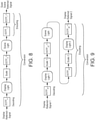
- Figure 8 shows a variation of conversion from display referred signals to scene referred signals. Sometimes it may be desirable to convert a display referred signal to a quasi scene referred signal, such as described in BBC White Paper 283.
- Figure 9 shows conversion from one display referred signal (for one target display) to another display referred signal (for a different display) according to an embodiment of the invention.
- Display referred signals differ in the peak level of signal they hold. Each signal relates to a specific display (hence “display referred”). The signal is incomplete without knowledge of the display, especially its peak level and the luminance level surrounding the display (because these values determine how the pictures should be rendered to achieve high subjective quality). This data may be conveyed with the signal as metadata, or the peak signal level may be measured, or estimated, from the signal itself, and the surounding luminance measured, or inferred from standards documents or from knowledge of current production practice.
- SMPTE ST 2084 provides two "Reference Viewing Environments" in Annex B, for HDTV and Digital Cinema.
- the HDTV environment has "a luminance of background of 8 to 12 cd/m2".
- the Digital Cinema environment only states the light level reflected from the screen and does not, directly, indicate the background illumination, which must be estimated.
- a display referred signal may therefore be considered a "container” for signals produced (or “mastered”) on displays with different brightness and viewing environments.
- This conversion is implemented by concatenating the processing before "Scene Light" of the conversion from display referred to scene referred described above (i.e. a first EOTF d1 , cascaded with a first scaling factor and an inverse first OOTF d1 -1 ), with the processing after "Scene Light" of the conversion from scene referred to display referred (i.e. a second OOTF d2 , cascaded with a second scaling factor and an inverse second EOTF d2 -1 ).
- the peak signal value for display referred signal 1 is needed to normalise the signal ("Scale 1").
- Peak signal 2 is used to multiply (“scale 2") the normalised signal to produce an absolute (linear) signal with the correct magnitude and dimensions cd/m 2 (and with background illumination to calculate a second value of gamma).
- scale 2 the normalised signal to produce an absolute (linear) signal with the correct magnitude and dimensions cd/m 2 (and with background illumination to calculate a second value of gamma).
- a scene referred signal e.g. a proprietary camera response curve such as Sony S-Log
- a quasi scene referred signal e.g. ITU-R BT 709, which uses ITU-R BT 1886 as a reference EOTF
- a display referred signal e.g. SMPTE ST 2084.
- three types of signal 9 types of conversion are possible and only 4 conversions are described above.
- the remaining conversions are between scene referred signals and quasi scene referred signals, which may also be useful. These conversions may be implemented by permuting the processing before and after "Scene Light" in methods above.
- This conversion may be implemented by concatenating the processing before "Scene Light” in Figure 5 (i.e. OETF s -1 ), with the processing after "Scene Light” in Figure 8 (i.e. OOTF r cascaded with EOTF r -1 ).
- This conversion may be implemented by concatenating the processing before "Scene Light” in Figure 6 (i.e. EOTF r cascaded with OOTF r -1 ), with the processing after "Scene Light” in Figure 7 (i.e. OETF s ).
- This conversion may be implemented by concatenating the processing before "Scene Light” in Figure 6 (i.e. a first EOTF r cascaded with a first OOTF r -1 ), with the processing after "Scene Light” in Figure 8 (i.e. a second OOTF r cascaded with a second EOTF r -1 ).
- This conversion may be implemented by concatenating the processing before "Scene Light” in Figure 5 (i.e. a first OETF s -1 ), with the processing after "Scene Light” in Figure 7 (i.e. a second OETF s ). This conversion technique is well known in the current art.
Landscapes
- Engineering & Computer Science (AREA)
- Multimedia (AREA)
- Signal Processing (AREA)
- Physics & Mathematics (AREA)
- General Physics & Mathematics (AREA)
- Theoretical Computer Science (AREA)
- Computer Hardware Design (AREA)
- Processing Of Color Television Signals (AREA)
- Image Processing (AREA)
- Controls And Circuits For Display Device (AREA)
- Picture Signal Circuits (AREA)
- Color Television Systems (AREA)
Applications Claiming Priority (2)
| Application Number | Priority Date | Filing Date | Title |
|---|---|---|---|
| GB1511495.2A GB2539917B (en) | 2015-06-30 | 2015-06-30 | Method and apparatus for conversion of HDR signals |
| PCT/GB2016/051983 WO2017001858A1 (en) | 2015-06-30 | 2016-06-30 | Method and apparatus for conversion of hdr signals |
Publications (2)
| Publication Number | Publication Date |
|---|---|
| EP3318052A1 EP3318052A1 (en) | 2018-05-09 |
| EP3318052B1 true EP3318052B1 (en) | 2022-03-16 |
Family
ID=53872472
Family Applications (1)
| Application Number | Title | Priority Date | Filing Date |
|---|---|---|---|
| EP16736590.7A Active EP3318052B1 (en) | 2015-06-30 | 2016-06-30 | Method and apparatus for conversion of hdr signals |
Country Status (9)
| Country | Link |
|---|---|
| US (2) | US10455209B2 (pl) |
| EP (1) | EP3318052B1 (pl) |
| JP (2) | JP6876007B2 (pl) |
| KR (1) | KR102670327B1 (pl) |
| AU (1) | AU2016285256B2 (pl) |
| ES (1) | ES2912904T3 (pl) |
| GB (1) | GB2539917B (pl) |
| PL (1) | PL3318052T3 (pl) |
| WO (1) | WO2017001858A1 (pl) |
Families Citing this family (59)
| Publication number | Priority date | Publication date | Assignee | Title |
|---|---|---|---|---|
| GB2539917B (en) | 2015-06-30 | 2021-04-07 | British Broadcasting Corp | Method and apparatus for conversion of HDR signals |
| EP3330959A4 (en) * | 2015-07-31 | 2019-07-17 | Sony Corporation | VIDEO SIGNAL PROCESSING DEVICE, METHOD FOR PROCESSING A VIDEO SIGNAL AND DISPLAY DEVICE |
| JP6320440B2 (ja) * | 2015-08-04 | 2018-05-09 | ドルビー ラボラトリーズ ライセンシング コーポレイション | ハイダイナミックレンジ信号のための信号再構成 |
| US10257393B2 (en) | 2016-02-12 | 2019-04-09 | Contrast, Inc. | Devices and methods for high dynamic range video |
| US10264196B2 (en) | 2016-02-12 | 2019-04-16 | Contrast, Inc. | Systems and methods for HDR video capture with a mobile device |
| WO2018031441A1 (en) | 2016-08-09 | 2018-02-15 | Contrast, Inc. | Real-time hdr video for vehicle control |
| KR102340082B1 (ko) * | 2016-09-20 | 2021-12-15 | 소니그룹주식회사 | 영상 신호 처리 장치, 영상 신호 처리 방법 및 영상 신호 처리 시스템 |
| JP6872693B2 (ja) * | 2016-09-28 | 2021-05-19 | パナソニックIpマネジメント株式会社 | 調整装置、調整方法およびプログラム |
| KR102554379B1 (ko) * | 2016-10-31 | 2023-07-11 | 엘지디스플레이 주식회사 | 하이 다이나믹 레인지 영상 처리 방법 및 영상 처리 모듈과 그를 이용한 표시 장치 |
| EP3367689A1 (en) * | 2017-02-24 | 2018-08-29 | Ymagis | Signal encoding and decoding for high contrast theatrical display |
| JP6860415B2 (ja) * | 2017-05-15 | 2021-04-14 | 日本放送協会 | 映像信号変換装置、ダイナミックレンジ変換装置およびそれらのプログラム |
| JP6784643B2 (ja) * | 2017-05-24 | 2020-11-11 | 日本放送協会 | 映像信号変換装置およびそのプログラム、ならびに、映像表示装置 |
| WO2019014057A1 (en) | 2017-07-10 | 2019-01-17 | Contrast, Inc. | Stereoscopic camera |
| CN119629402A (zh) | 2017-10-12 | 2025-03-14 | 索尼公司 | 接收设备和接收方法 |
| US10832613B2 (en) | 2018-03-07 | 2020-11-10 | At&T Intellectual Property I, L.P. | Image format conversion using luminance-adaptive dithering |
| EP3557875A1 (en) * | 2018-04-19 | 2019-10-23 | Ymagis | Multidynamic transport and restitution system for theatrical display |
| US10951888B2 (en) | 2018-06-04 | 2021-03-16 | Contrast, Inc. | Compressed high dynamic range video |
| AU2019232894B2 (en) * | 2018-06-07 | 2020-04-30 | Boris Pavic | A system and methodology for the high-fidelity display of artwork images |
| JP7003304B2 (ja) * | 2018-06-18 | 2022-01-20 | ドルビー ラボラトリーズ ライセンシング コーポレイション | 撮像方法およびシステム |
| CN108900823B (zh) | 2018-07-05 | 2019-07-12 | 华为技术有限公司 | 一种视频信号处理的方法及装置 |
| JP7096731B2 (ja) * | 2018-08-03 | 2022-07-06 | 日本放送協会 | 信号処理装置、表示装置、撮像装置及びプログラム |
| US11303932B2 (en) | 2018-08-14 | 2022-04-12 | Contrast, Inc. | Image compression |
| US11532261B1 (en) | 2018-10-25 | 2022-12-20 | Baylor University | System and method for a multi-primary wide gamut color system |
| US11403987B2 (en) | 2018-10-25 | 2022-08-02 | Baylor University | System and method for a multi-primary wide gamut color system |
| US11488510B2 (en) | 2018-10-25 | 2022-11-01 | Baylor University | System and method for a multi-primary wide gamut color system |
| US10997896B2 (en) | 2018-10-25 | 2021-05-04 | Baylor University | System and method for a six-primary wide gamut color system |
| US11315467B1 (en) | 2018-10-25 | 2022-04-26 | Baylor University | System and method for a multi-primary wide gamut color system |
| US10950162B2 (en) | 2018-10-25 | 2021-03-16 | Baylor University | System and method for a six-primary wide gamut color system |
| US11069279B2 (en) * | 2018-10-25 | 2021-07-20 | Baylor University | System and method for a multi-primary wide gamut color system |
| US11037481B1 (en) | 2018-10-25 | 2021-06-15 | Baylor University | System and method for a multi-primary wide gamut color system |
| US11030934B2 (en) | 2018-10-25 | 2021-06-08 | Baylor University | System and method for a multi-primary wide gamut color system |
| US11289003B2 (en) | 2018-10-25 | 2022-03-29 | Baylor University | System and method for a multi-primary wide gamut color system |
| US11373575B2 (en) | 2018-10-25 | 2022-06-28 | Baylor University | System and method for a multi-primary wide gamut color system |
| US10607527B1 (en) | 2018-10-25 | 2020-03-31 | Baylor University | System and method for a six-primary wide gamut color system |
| US12444337B2 (en) | 2018-10-25 | 2025-10-14 | Baylor University | System and method for a multi-primary wide gamut color system |
| US11069280B2 (en) | 2018-10-25 | 2021-07-20 | Baylor University | System and method for a multi-primary wide gamut color system |
| US12555507B2 (en) | 2018-10-25 | 2026-02-17 | Baylor University | System and method for a multi-primary wide gamut color system |
| US11043157B2 (en) | 2018-10-25 | 2021-06-22 | Baylor University | System and method for a six-primary wide gamut color system |
| US11341890B2 (en) | 2018-10-25 | 2022-05-24 | Baylor University | System and method for a multi-primary wide gamut color system |
| US11062638B2 (en) | 2018-10-25 | 2021-07-13 | Baylor University | System and method for a multi-primary wide gamut color system |
| US11410593B2 (en) | 2018-10-25 | 2022-08-09 | Baylor University | System and method for a multi-primary wide gamut color system |
| US11189210B2 (en) | 2018-10-25 | 2021-11-30 | Baylor University | System and method for a multi-primary wide gamut color system |
| US11475819B2 (en) | 2018-10-25 | 2022-10-18 | Baylor University | System and method for a multi-primary wide gamut color system |
| US10950161B2 (en) | 2018-10-25 | 2021-03-16 | Baylor University | System and method for a six-primary wide gamut color system |
| US11289000B2 (en) | 2018-10-25 | 2022-03-29 | Baylor University | System and method for a multi-primary wide gamut color system |
| US11587491B1 (en) | 2018-10-25 | 2023-02-21 | Baylor University | System and method for a multi-primary wide gamut color system |
| US12444334B2 (en) | 2018-10-25 | 2025-10-14 | Baylor University | System and method for a multi-primary wide gamut color system |
| US12475826B2 (en) | 2018-10-25 | 2025-11-18 | Baylor University | System and method for a multi-primary wide gamut color system |
| KR102794423B1 (ko) * | 2019-11-15 | 2025-04-11 | 삼성전자주식회사 | 영상 제공 장치 및 이에 의한 영상 제공 방법, 및 디스플레이 장치 및 이에 의한 디스플레이 방법 |
| KR102847073B1 (ko) * | 2020-10-21 | 2025-08-19 | 삼성디스플레이 주식회사 | 하이 다이내믹 레인지 후-처리 장치, 및 이를 포함하는 표시 장치 |
| US11302287B1 (en) | 2020-11-10 | 2022-04-12 | Microsoft Technology Licensing, Llc | Color correction in computing systems for color vision deficiency |
| US20220191381A1 (en) * | 2020-12-11 | 2022-06-16 | Contrast, Inc. | Dynamic transfer function for reversible encoding |
| JP2024518827A (ja) * | 2021-05-19 | 2024-05-07 | ドルビー ラボラトリーズ ライセンシング コーポレイション | 周囲光および/または非ディスプレイ由来の表面光に対する位置変化する適応性のあるディスプレイ管理 |
| GB2608990B (en) * | 2021-07-08 | 2024-10-30 | British Broadcasting Corp | Method and apparatus for conversion of HDR signals |
| GB2625218B (en) * | 2021-07-08 | 2024-11-13 | British Broadcasting Corp | Method and apparatus for conversion of HDR signals |
| US11657778B2 (en) | 2021-09-10 | 2023-05-23 | Dell Products L.P. | On demand display source presentation at a partial display area |
| US20250054204A1 (en) * | 2021-10-01 | 2025-02-13 | Dolby Laboratories Licensing Corporation | Encoding and decoding multiple-intent images and video using metadata |
| CN116416344A (zh) * | 2021-12-30 | 2023-07-11 | 北京字跳网络技术有限公司 | 图像处理方法、装置、电子设备及可读存储介质 |
| US12462772B1 (en) | 2024-06-20 | 2025-11-04 | 6P Color, Inc. | System and method for conversion from XYZ to multiple primaries using pseudo white points |
Citations (1)
| Publication number | Priority date | Publication date | Assignee | Title |
|---|---|---|---|---|
| US20130076974A1 (en) * | 2011-09-26 | 2013-03-28 | Dolby Laboratories Licensing Corporation | Image Formats and Related Methods and Apparatuses |
Family Cites Families (8)
| Publication number | Priority date | Publication date | Assignee | Title |
|---|---|---|---|---|
| US7227666B1 (en) * | 2000-09-01 | 2007-06-05 | Adobe Systems Incorporated | Dynamic selection of rendering intent for color proofing transforms |
| US20050117799A1 (en) * | 2003-12-01 | 2005-06-02 | Chiou-Shann Fuh | Method and apparatus for transforming a high dynamic range image into a low dynamic range image |
| JP4145888B2 (ja) * | 2005-03-23 | 2008-09-03 | セイコーエプソン株式会社 | 表示装置および表示方法 |
| US9443327B2 (en) * | 2008-08-06 | 2016-09-13 | Adobe Systems Incorporated | Rendering and un-rendering using profile replacement |
| CN103843058B (zh) * | 2011-09-27 | 2016-11-23 | 皇家飞利浦有限公司 | 用于图像的动态范围变换的装置和方法 |
| RU2633128C2 (ru) * | 2013-02-21 | 2017-10-11 | Конинклейке Филипс Н.В. | Улучшенные способы и устройства кодирования и декодирования hdr изображения |
| RU2670782C9 (ru) * | 2013-07-18 | 2018-11-23 | Конинклейке Филипс Н.В. | Способы и устройства для создания функций отображения кода для кодирования изображения hdr и способы и устройства для использования таких кодированных изображений |
| GB2539917B (en) | 2015-06-30 | 2021-04-07 | British Broadcasting Corp | Method and apparatus for conversion of HDR signals |
-
2015
- 2015-06-30 GB GB1511495.2A patent/GB2539917B/en active Active
-
2016
- 2016-06-29 US US15/196,276 patent/US10455209B2/en active Active
- 2016-06-30 EP EP16736590.7A patent/EP3318052B1/en active Active
- 2016-06-30 WO PCT/GB2016/051983 patent/WO2017001858A1/en not_active Ceased
- 2016-06-30 KR KR1020187002322A patent/KR102670327B1/ko active Active
- 2016-06-30 ES ES16736590T patent/ES2912904T3/es active Active
- 2016-06-30 JP JP2017568260A patent/JP6876007B2/ja active Active
- 2016-06-30 AU AU2016285256A patent/AU2016285256B2/en active Active
- 2016-06-30 PL PL16736590.7T patent/PL3318052T3/pl unknown
-
2019
- 2019-09-27 US US16/585,570 patent/US10848729B2/en active Active
-
2021
- 2021-04-23 JP JP2021073559A patent/JP7101288B2/ja active Active
Patent Citations (1)
| Publication number | Priority date | Publication date | Assignee | Title |
|---|---|---|---|---|
| US20130076974A1 (en) * | 2011-09-26 | 2013-03-28 | Dolby Laboratories Licensing Corporation | Image Formats and Related Methods and Apparatuses |
Non-Patent Citations (1)
| Title |
|---|
| COTTON A ET AL: "BBC's response to CfE for HDR Video Coding (Category 3a)", 112. MPEG MEETING; 22-6-2015 - 26-6-2015; WARSAW; (MOTION PICTURE EXPERT GROUP OR ISO/IEC JTC1/SC29/WG11),, no. m36249, 18 June 2015 (2015-06-18), XP030064617 * |
Also Published As
| Publication number | Publication date |
|---|---|
| US10848729B2 (en) | 2020-11-24 |
| GB2539917B (en) | 2021-04-07 |
| AU2016285256B2 (en) | 2020-09-03 |
| US10455209B2 (en) | 2019-10-22 |
| ES2912904T3 (es) | 2022-05-30 |
| JP6876007B2 (ja) | 2021-05-26 |
| BR112018000078A2 (pt) | 2018-08-28 |
| JP2018526864A (ja) | 2018-09-13 |
| WO2017001858A1 (en) | 2017-01-05 |
| AU2016285256A1 (en) | 2018-02-01 |
| JP7101288B2 (ja) | 2022-07-14 |
| CA2990569A1 (en) | 2017-01-05 |
| PL3318052T3 (pl) | 2022-07-18 |
| GB2539917A (en) | 2017-01-04 |
| US20170006273A1 (en) | 2017-01-05 |
| US20200099909A1 (en) | 2020-03-26 |
| JP2021114327A (ja) | 2021-08-05 |
| KR20180039053A (ko) | 2018-04-17 |
| EP3318052A1 (en) | 2018-05-09 |
| GB201511495D0 (en) | 2015-08-12 |
| KR102670327B1 (ko) | 2024-05-30 |
Similar Documents
| Publication | Publication Date | Title |
|---|---|---|
| US10848729B2 (en) | Method and apparatus for conversion of HDR signals | |
| TWI684166B (zh) | 針對高動態範圍信號的信號重塑形 | |
| RU2592074C1 (ru) | Способ и устройство для преобразования данных изображения | |
| US20180367778A1 (en) | Method And Apparatus For Conversion Of HDR Signals | |
| US20150256860A1 (en) | Graphics Blending for High Dynamic Range Video | |
| EP3446284B1 (en) | Method and apparatus for conversion of dynamic range of video signals | |
| US10645359B2 (en) | Method for processing a digital image, device, terminal equipment and associated computer program | |
| US7656462B2 (en) | Systems and methods for modifying master film for viewing at different viewing locations | |
| JP6742417B2 (ja) | デジタル画像の処理方法、付随する装置、端末機器およびコンピュータプログラム | |
| CA2990569C (en) | Method and apparatus for conversion of hdr signals | |
| US7961939B2 (en) | Color transforming method | |
| KR100461018B1 (ko) | 디지털 텔레비젼의 자연영상 생성장치 및 방법 | |
| Sharma | Exploring the basic concepts of HDR: dynamic range, gamma curves, and wide color gamut | |
| Thompson | Conversion of Conventional Video Display for High Dynamic Range Televisions | |
| CN118044189A (zh) | 使用元数据编码和解码多意图图像和视频 | |
| BR112018000078B1 (pt) | Método e aparelho para conversão de sinais de hdr |
Legal Events
| Date | Code | Title | Description |
|---|---|---|---|
| STAA | Information on the status of an ep patent application or granted ep patent |
Free format text: STATUS: THE INTERNATIONAL PUBLICATION HAS BEEN MADE |
|
| PUAI | Public reference made under article 153(3) epc to a published international application that has entered the european phase |
Free format text: ORIGINAL CODE: 0009012 |
|
| STAA | Information on the status of an ep patent application or granted ep patent |
Free format text: STATUS: REQUEST FOR EXAMINATION WAS MADE |
|
| 17P | Request for examination filed |
Effective date: 20180124 |
|
| AK | Designated contracting states |
Kind code of ref document: A1 Designated state(s): AL AT BE BG CH CY CZ DE DK EE ES FI FR GB GR HR HU IE IS IT LI LT LU LV MC MK MT NL NO PL PT RO RS SE SI SK SM TR |
|
| AX | Request for extension of the european patent |
Extension state: BA ME |
|
| DAV | Request for validation of the european patent (deleted) | ||
| DAX | Request for extension of the european patent (deleted) | ||
| STAA | Information on the status of an ep patent application or granted ep patent |
Free format text: STATUS: EXAMINATION IS IN PROGRESS |
|
| 17Q | First examination report despatched |
Effective date: 20190521 |
|
| GRAP | Despatch of communication of intention to grant a patent |
Free format text: ORIGINAL CODE: EPIDOSNIGR1 |
|
| STAA | Information on the status of an ep patent application or granted ep patent |
Free format text: STATUS: GRANT OF PATENT IS INTENDED |
|
| RIC1 | Information provided on ipc code assigned before grant |
Ipc: H04N 9/68 20060101ALI20210916BHEP Ipc: G09G 5/10 20060101ALI20210916BHEP Ipc: G06T 5/00 20060101ALI20210916BHEP Ipc: G09G 5/02 20060101ALI20210916BHEP Ipc: H04N 19/00 20140101ALI20210916BHEP Ipc: H04N 5/202 20060101AFI20210916BHEP |
|
| INTG | Intention to grant announced |
Effective date: 20211007 |
|
| GRAS | Grant fee paid |
Free format text: ORIGINAL CODE: EPIDOSNIGR3 |
|
| GRAA | (expected) grant |
Free format text: ORIGINAL CODE: 0009210 |
|
| STAA | Information on the status of an ep patent application or granted ep patent |
Free format text: STATUS: THE PATENT HAS BEEN GRANTED |
|
| RBV | Designated contracting states (corrected) |
Designated state(s): AL AT BE BG CH CY CZ DE DK EE ES FI FR GR HR HU IE IS IT LI LT LU LV MC MK MT NL NO PL PT RO RS SE SI SK SM TR |
|
| AK | Designated contracting states |
Kind code of ref document: B1 Designated state(s): AL AT BE BG CH CY CZ DE DK EE ES FI FR GR HR HU IE IS IT LI LT LU LV MC MK MT NL NO PL PT RO RS SE SI SK SM TR |
|
| REG | Reference to a national code |
Ref country code: CH Ref legal event code: EP Ref country code: DE Ref legal event code: R096 Ref document number: 602016070054 Country of ref document: DE |
|
| REG | Reference to a national code |
Ref country code: IE Ref legal event code: FG4D |
|
| REG | Reference to a national code |
Ref country code: AT Ref legal event code: REF Ref document number: 1476687 Country of ref document: AT Kind code of ref document: T Effective date: 20220415 |
|
| REG | Reference to a national code |
Ref country code: NL Ref legal event code: FP |
|
| REG | Reference to a national code |
Ref country code: ES Ref legal event code: FG2A Ref document number: 2912904 Country of ref document: ES Kind code of ref document: T3 Effective date: 20220530 |
|
| REG | Reference to a national code |
Ref country code: GR Ref legal event code: EP Ref document number: 20220400955 Country of ref document: GR Effective date: 20220608 |
|
| REG | Reference to a national code |
Ref country code: LT Ref legal event code: MG9D |
|
| PG25 | Lapsed in a contracting state [announced via postgrant information from national office to epo] |
Ref country code: SE Free format text: LAPSE BECAUSE OF FAILURE TO SUBMIT A TRANSLATION OF THE DESCRIPTION OR TO PAY THE FEE WITHIN THE PRESCRIBED TIME-LIMIT Effective date: 20220316 Ref country code: RS Free format text: LAPSE BECAUSE OF FAILURE TO SUBMIT A TRANSLATION OF THE DESCRIPTION OR TO PAY THE FEE WITHIN THE PRESCRIBED TIME-LIMIT Effective date: 20220316 Ref country code: NO Free format text: LAPSE BECAUSE OF FAILURE TO SUBMIT A TRANSLATION OF THE DESCRIPTION OR TO PAY THE FEE WITHIN THE PRESCRIBED TIME-LIMIT Effective date: 20220616 Ref country code: LT Free format text: LAPSE BECAUSE OF FAILURE TO SUBMIT A TRANSLATION OF THE DESCRIPTION OR TO PAY THE FEE WITHIN THE PRESCRIBED TIME-LIMIT Effective date: 20220316 Ref country code: HR Free format text: LAPSE BECAUSE OF FAILURE TO SUBMIT A TRANSLATION OF THE DESCRIPTION OR TO PAY THE FEE WITHIN THE PRESCRIBED TIME-LIMIT Effective date: 20220316 Ref country code: BG Free format text: LAPSE BECAUSE OF FAILURE TO SUBMIT A TRANSLATION OF THE DESCRIPTION OR TO PAY THE FEE WITHIN THE PRESCRIBED TIME-LIMIT Effective date: 20220616 |
|
| REG | Reference to a national code |
Ref country code: AT Ref legal event code: MK05 Ref document number: 1476687 Country of ref document: AT Kind code of ref document: T Effective date: 20220316 |
|
| PG25 | Lapsed in a contracting state [announced via postgrant information from national office to epo] |
Ref country code: LV Free format text: LAPSE BECAUSE OF FAILURE TO SUBMIT A TRANSLATION OF THE DESCRIPTION OR TO PAY THE FEE WITHIN THE PRESCRIBED TIME-LIMIT Effective date: 20220316 Ref country code: FI Free format text: LAPSE BECAUSE OF FAILURE TO SUBMIT A TRANSLATION OF THE DESCRIPTION OR TO PAY THE FEE WITHIN THE PRESCRIBED TIME-LIMIT Effective date: 20220316 |
|
| PG25 | Lapsed in a contracting state [announced via postgrant information from national office to epo] |
Ref country code: SM Free format text: LAPSE BECAUSE OF FAILURE TO SUBMIT A TRANSLATION OF THE DESCRIPTION OR TO PAY THE FEE WITHIN THE PRESCRIBED TIME-LIMIT Effective date: 20220316 Ref country code: SK Free format text: LAPSE BECAUSE OF FAILURE TO SUBMIT A TRANSLATION OF THE DESCRIPTION OR TO PAY THE FEE WITHIN THE PRESCRIBED TIME-LIMIT Effective date: 20220316 Ref country code: RO Free format text: LAPSE BECAUSE OF FAILURE TO SUBMIT A TRANSLATION OF THE DESCRIPTION OR TO PAY THE FEE WITHIN THE PRESCRIBED TIME-LIMIT Effective date: 20220316 Ref country code: PT Free format text: LAPSE BECAUSE OF FAILURE TO SUBMIT A TRANSLATION OF THE DESCRIPTION OR TO PAY THE FEE WITHIN THE PRESCRIBED TIME-LIMIT Effective date: 20220718 Ref country code: EE Free format text: LAPSE BECAUSE OF FAILURE TO SUBMIT A TRANSLATION OF THE DESCRIPTION OR TO PAY THE FEE WITHIN THE PRESCRIBED TIME-LIMIT Effective date: 20220316 Ref country code: AT Free format text: LAPSE BECAUSE OF FAILURE TO SUBMIT A TRANSLATION OF THE DESCRIPTION OR TO PAY THE FEE WITHIN THE PRESCRIBED TIME-LIMIT Effective date: 20220316 |
|
| PG25 | Lapsed in a contracting state [announced via postgrant information from national office to epo] |
Ref country code: IS Free format text: LAPSE BECAUSE OF FAILURE TO SUBMIT A TRANSLATION OF THE DESCRIPTION OR TO PAY THE FEE WITHIN THE PRESCRIBED TIME-LIMIT Effective date: 20220716 Ref country code: AL Free format text: LAPSE BECAUSE OF FAILURE TO SUBMIT A TRANSLATION OF THE DESCRIPTION OR TO PAY THE FEE WITHIN THE PRESCRIBED TIME-LIMIT Effective date: 20220316 |
|
| REG | Reference to a national code |
Ref country code: DE Ref legal event code: R097 Ref document number: 602016070054 Country of ref document: DE |
|
| PLBE | No opposition filed within time limit |
Free format text: ORIGINAL CODE: 0009261 |
|
| STAA | Information on the status of an ep patent application or granted ep patent |
Free format text: STATUS: NO OPPOSITION FILED WITHIN TIME LIMIT |
|
| PG25 | Lapsed in a contracting state [announced via postgrant information from national office to epo] |
Ref country code: MC Free format text: LAPSE BECAUSE OF FAILURE TO SUBMIT A TRANSLATION OF THE DESCRIPTION OR TO PAY THE FEE WITHIN THE PRESCRIBED TIME-LIMIT Effective date: 20220316 Ref country code: DK Free format text: LAPSE BECAUSE OF FAILURE TO SUBMIT A TRANSLATION OF THE DESCRIPTION OR TO PAY THE FEE WITHIN THE PRESCRIBED TIME-LIMIT Effective date: 20220316 |
|
| REG | Reference to a national code |
Ref country code: CH Ref legal event code: PL |
|
| REG | Reference to a national code |
Ref country code: BE Ref legal event code: MM Effective date: 20220630 |
|
| 26N | No opposition filed |
Effective date: 20221219 |
|
| PG25 | Lapsed in a contracting state [announced via postgrant information from national office to epo] |
Ref country code: SI Free format text: LAPSE BECAUSE OF FAILURE TO SUBMIT A TRANSLATION OF THE DESCRIPTION OR TO PAY THE FEE WITHIN THE PRESCRIBED TIME-LIMIT Effective date: 20220316 |
|
| PG25 | Lapsed in a contracting state [announced via postgrant information from national office to epo] |
Ref country code: LU Free format text: LAPSE BECAUSE OF NON-PAYMENT OF DUE FEES Effective date: 20220630 Ref country code: LI Free format text: LAPSE BECAUSE OF NON-PAYMENT OF DUE FEES Effective date: 20220630 Ref country code: IE Free format text: LAPSE BECAUSE OF NON-PAYMENT OF DUE FEES Effective date: 20220630 Ref country code: CH Free format text: LAPSE BECAUSE OF NON-PAYMENT OF DUE FEES Effective date: 20220630 |
|
| PG25 | Lapsed in a contracting state [announced via postgrant information from national office to epo] |
Ref country code: BE Free format text: LAPSE BECAUSE OF NON-PAYMENT OF DUE FEES Effective date: 20220630 |
|
| P01 | Opt-out of the competence of the unified patent court (upc) registered |
Effective date: 20230330 |
|
| PG25 | Lapsed in a contracting state [announced via postgrant information from national office to epo] |
Ref country code: HU Free format text: LAPSE BECAUSE OF FAILURE TO SUBMIT A TRANSLATION OF THE DESCRIPTION OR TO PAY THE FEE WITHIN THE PRESCRIBED TIME-LIMIT; INVALID AB INITIO Effective date: 20160630 |
|
| PG25 | Lapsed in a contracting state [announced via postgrant information from national office to epo] |
Ref country code: MK Free format text: LAPSE BECAUSE OF FAILURE TO SUBMIT A TRANSLATION OF THE DESCRIPTION OR TO PAY THE FEE WITHIN THE PRESCRIBED TIME-LIMIT Effective date: 20220316 Ref country code: CY Free format text: LAPSE BECAUSE OF FAILURE TO SUBMIT A TRANSLATION OF THE DESCRIPTION OR TO PAY THE FEE WITHIN THE PRESCRIBED TIME-LIMIT Effective date: 20220316 |
|
| PG25 | Lapsed in a contracting state [announced via postgrant information from national office to epo] |
Ref country code: MT Free format text: LAPSE BECAUSE OF FAILURE TO SUBMIT A TRANSLATION OF THE DESCRIPTION OR TO PAY THE FEE WITHIN THE PRESCRIBED TIME-LIMIT Effective date: 20220316 |
|
| PGFP | Annual fee paid to national office [announced via postgrant information from national office to epo] |
Ref country code: NL Payment date: 20250516 Year of fee payment: 10 |
|
| PGFP | Annual fee paid to national office [announced via postgrant information from national office to epo] |
Ref country code: DE Payment date: 20250507 Year of fee payment: 10 Ref country code: PL Payment date: 20250414 Year of fee payment: 10 |
|
| PGFP | Annual fee paid to national office [announced via postgrant information from national office to epo] |
Ref country code: IT Payment date: 20250522 Year of fee payment: 10 |
|
| PGFP | Annual fee paid to national office [announced via postgrant information from national office to epo] |
Ref country code: FR Payment date: 20250508 Year of fee payment: 10 |
|
| PGFP | Annual fee paid to national office [announced via postgrant information from national office to epo] |
Ref country code: GR Payment date: 20250516 Year of fee payment: 10 |
|
| PGFP | Annual fee paid to national office [announced via postgrant information from national office to epo] |
Ref country code: TR Payment date: 20250626 Year of fee payment: 10 |
|
| PGFP | Annual fee paid to national office [announced via postgrant information from national office to epo] |
Ref country code: CZ Payment date: 20250618 Year of fee payment: 10 |
|
| PGFP | Annual fee paid to national office [announced via postgrant information from national office to epo] |
Ref country code: ES Payment date: 20250707 Year of fee payment: 10 |