EP3316643A2 - Systèmes et procédés de programmation semi-persistante de communications sans fil - Google Patents
Systèmes et procédés de programmation semi-persistante de communications sans fil Download PDFInfo
- Publication number
- EP3316643A2 EP3316643A2 EP17196578.3A EP17196578A EP3316643A2 EP 3316643 A2 EP3316643 A2 EP 3316643A2 EP 17196578 A EP17196578 A EP 17196578A EP 3316643 A2 EP3316643 A2 EP 3316643A2
- Authority
- EP
- European Patent Office
- Prior art keywords
- sps
- pdsch
- transmission
- pdcch
- reference signal
- Prior art date
- Legal status (The legal status is an assumption and is not a legal conclusion. Google has not performed a legal analysis and makes no representation as to the accuracy of the status listed.)
- Granted
Links
- 238000004891 communication Methods 0.000 title claims abstract description 182
- 238000000034 method Methods 0.000 title claims abstract description 119
- 230000005540 biological transmission Effects 0.000 claims abstract description 174
- 230000004913 activation Effects 0.000 claims abstract description 114
- 108010076504 Protein Sorting Signals Proteins 0.000 claims abstract description 54
- 230000008569 process Effects 0.000 claims abstract description 52
- 238000012545 processing Methods 0.000 claims description 64
- 230000011664 signaling Effects 0.000 claims description 58
- 238000013507 mapping Methods 0.000 claims description 21
- 238000010586 diagram Methods 0.000 description 15
- 230000006870 function Effects 0.000 description 4
- 238000003491 array Methods 0.000 description 3
- 125000004122 cyclic group Chemical group 0.000 description 3
- 230000004048 modification Effects 0.000 description 3
- 238000012986 modification Methods 0.000 description 3
- 238000010200 validation analysis Methods 0.000 description 3
- 238000005516 engineering process Methods 0.000 description 2
- 230000007274 generation of a signal involved in cell-cell signaling Effects 0.000 description 2
- 238000010295 mobile communication Methods 0.000 description 2
- 238000012544 monitoring process Methods 0.000 description 2
- 230000003287 optical effect Effects 0.000 description 2
- 208000032369 Primary transmission Diseases 0.000 description 1
- 230000003213 activating effect Effects 0.000 description 1
- 230000004075 alteration Effects 0.000 description 1
- 230000002238 attenuated effect Effects 0.000 description 1
- 230000001413 cellular effect Effects 0.000 description 1
- 239000003795 chemical substances by application Substances 0.000 description 1
- 239000004973 liquid crystal related substance Substances 0.000 description 1
- 230000007774 longterm Effects 0.000 description 1
- 238000004519 manufacturing process Methods 0.000 description 1
- 239000000463 material Substances 0.000 description 1
- 230000007246 mechanism Effects 0.000 description 1
- 239000013307 optical fiber Substances 0.000 description 1
- 230000009467 reduction Effects 0.000 description 1
- 238000013468 resource allocation Methods 0.000 description 1
- 239000004065 semiconductor Substances 0.000 description 1
- 230000008054 signal transmission Effects 0.000 description 1
- 238000001228 spectrum Methods 0.000 description 1
- 239000004557 technical material Substances 0.000 description 1
- 238000000411 transmission spectrum Methods 0.000 description 1
Images


Classifications
-
- H—ELECTRICITY
- H04—ELECTRIC COMMUNICATION TECHNIQUE
- H04W—WIRELESS COMMUNICATION NETWORKS
- H04W28/00—Network traffic management; Network resource management
- H04W28/16—Central resource management; Negotiation of resources or communication parameters, e.g. negotiating bandwidth or QoS [Quality of Service]
- H04W28/24—Negotiating SLA [Service Level Agreement]; Negotiating QoS [Quality of Service]
-
- H—ELECTRICITY
- H04—ELECTRIC COMMUNICATION TECHNIQUE
- H04W—WIRELESS COMMUNICATION NETWORKS
- H04W72/00—Local resource management
- H04W72/04—Wireless resource allocation
- H04W72/11—Semi-persistent scheduling
-
- H—ELECTRICITY
- H04—ELECTRIC COMMUNICATION TECHNIQUE
- H04L—TRANSMISSION OF DIGITAL INFORMATION, e.g. TELEGRAPHIC COMMUNICATION
- H04L5/00—Arrangements affording multiple use of the transmission path
- H04L5/003—Arrangements for allocating sub-channels of the transmission path
- H04L5/0053—Allocation of signaling, i.e. of overhead other than pilot signals
-
- H—ELECTRICITY
- H04—ELECTRIC COMMUNICATION TECHNIQUE
- H04B—TRANSMISSION
- H04B7/00—Radio transmission systems, i.e. using radiation field
- H04B7/02—Diversity systems; Multi-antenna system, i.e. transmission or reception using multiple antennas
- H04B7/022—Site diversity; Macro-diversity
- H04B7/024—Co-operative use of antennas of several sites, e.g. in co-ordinated multipoint or co-operative multiple-input multiple-output [MIMO] systems
-
- H—ELECTRICITY
- H04—ELECTRIC COMMUNICATION TECHNIQUE
- H04J—MULTIPLEX COMMUNICATION
- H04J11/00—Orthogonal multiplex systems, e.g. using WALSH codes
- H04J11/0069—Cell search, i.e. determining cell identity [cell-ID]
-
- H—ELECTRICITY
- H04—ELECTRIC COMMUNICATION TECHNIQUE
- H04L—TRANSMISSION OF DIGITAL INFORMATION, e.g. TELEGRAPHIC COMMUNICATION
- H04L5/00—Arrangements affording multiple use of the transmission path
- H04L5/003—Arrangements for allocating sub-channels of the transmission path
- H04L5/0032—Distributed allocation, i.e. involving a plurality of allocating devices, each making partial allocation
- H04L5/0035—Resource allocation in a cooperative multipoint environment
-
- H—ELECTRICITY
- H04—ELECTRIC COMMUNICATION TECHNIQUE
- H04L—TRANSMISSION OF DIGITAL INFORMATION, e.g. TELEGRAPHIC COMMUNICATION
- H04L5/00—Arrangements affording multiple use of the transmission path
- H04L5/0091—Signaling for the administration of the divided path
- H04L5/0096—Indication of changes in allocation
- H04L5/0098—Signalling of the activation or deactivation of component carriers, subcarriers or frequency bands
-
- H—ELECTRICITY
- H04—ELECTRIC COMMUNICATION TECHNIQUE
- H04W—WIRELESS COMMUNICATION NETWORKS
- H04W4/00—Services specially adapted for wireless communication networks; Facilities therefor
- H04W4/70—Services for machine-to-machine communication [M2M] or machine type communication [MTC]
-
- H—ELECTRICITY
- H04—ELECTRIC COMMUNICATION TECHNIQUE
- H04W—WIRELESS COMMUNICATION NETWORKS
- H04W52/00—Power management, e.g. TPC [Transmission Power Control], power saving or power classes
- H04W52/02—Power saving arrangements
- H04W52/0209—Power saving arrangements in terminal devices
- H04W52/0212—Power saving arrangements in terminal devices managed by the network, e.g. network or access point is master and terminal is slave
- H04W52/0216—Power saving arrangements in terminal devices managed by the network, e.g. network or access point is master and terminal is slave using a pre-established activity schedule, e.g. traffic indication frame
-
- H—ELECTRICITY
- H04—ELECTRIC COMMUNICATION TECHNIQUE
- H04W—WIRELESS COMMUNICATION NETWORKS
- H04W52/00—Power management, e.g. TPC [Transmission Power Control], power saving or power classes
- H04W52/02—Power saving arrangements
- H04W52/0209—Power saving arrangements in terminal devices
- H04W52/0225—Power saving arrangements in terminal devices using monitoring of external events, e.g. the presence of a signal
- H04W52/0235—Power saving arrangements in terminal devices using monitoring of external events, e.g. the presence of a signal where the received signal is a power saving command
-
- H—ELECTRICITY
- H04—ELECTRIC COMMUNICATION TECHNIQUE
- H04W—WIRELESS COMMUNICATION NETWORKS
- H04W72/00—Local resource management
- H04W72/20—Control channels or signalling for resource management
- H04W72/23—Control channels or signalling for resource management in the downlink direction of a wireless link, i.e. towards a terminal
- H04W72/231—Control channels or signalling for resource management in the downlink direction of a wireless link, i.e. towards a terminal the control data signalling from the layers above the physical layer, e.g. RRC or MAC-CE signalling
-
- H—ELECTRICITY
- H04—ELECTRIC COMMUNICATION TECHNIQUE
- H04W—WIRELESS COMMUNICATION NETWORKS
- H04W72/00—Local resource management
- H04W72/20—Control channels or signalling for resource management
- H04W72/23—Control channels or signalling for resource management in the downlink direction of a wireless link, i.e. towards a terminal
- H04W72/232—Control channels or signalling for resource management in the downlink direction of a wireless link, i.e. towards a terminal the control data signalling from the physical layer, e.g. DCI signalling
-
- H—ELECTRICITY
- H04—ELECTRIC COMMUNICATION TECHNIQUE
- H04L—TRANSMISSION OF DIGITAL INFORMATION, e.g. TELEGRAPHIC COMMUNICATION
- H04L27/00—Modulated-carrier systems
- H04L27/26—Systems using multi-frequency codes
- H04L27/2601—Multicarrier modulation systems
- H04L27/2602—Signal structure
- H04L27/261—Details of reference signals
- H04L27/2613—Structure of the reference signals
-
- H—ELECTRICITY
- H04—ELECTRIC COMMUNICATION TECHNIQUE
- H04L—TRANSMISSION OF DIGITAL INFORMATION, e.g. TELEGRAPHIC COMMUNICATION
- H04L5/00—Arrangements affording multiple use of the transmission path
- H04L5/003—Arrangements for allocating sub-channels of the transmission path
- H04L5/0048—Allocation of pilot signals, i.e. of signals known to the receiver
- H04L5/005—Allocation of pilot signals, i.e. of signals known to the receiver of common pilots, i.e. pilots destined for multiple users or terminals
-
- H—ELECTRICITY
- H04—ELECTRIC COMMUNICATION TECHNIQUE
- H04L—TRANSMISSION OF DIGITAL INFORMATION, e.g. TELEGRAPHIC COMMUNICATION
- H04L5/00—Arrangements affording multiple use of the transmission path
- H04L5/003—Arrangements for allocating sub-channels of the transmission path
- H04L5/0048—Allocation of pilot signals, i.e. of signals known to the receiver
- H04L5/0051—Allocation of pilot signals, i.e. of signals known to the receiver of dedicated pilots, i.e. pilots destined for a single user or terminal
-
- Y—GENERAL TAGGING OF NEW TECHNOLOGICAL DEVELOPMENTS; GENERAL TAGGING OF CROSS-SECTIONAL TECHNOLOGIES SPANNING OVER SEVERAL SECTIONS OF THE IPC; TECHNICAL SUBJECTS COVERED BY FORMER USPC CROSS-REFERENCE ART COLLECTIONS [XRACs] AND DIGESTS
- Y02—TECHNOLOGIES OR APPLICATIONS FOR MITIGATION OR ADAPTATION AGAINST CLIMATE CHANGE
- Y02D—CLIMATE CHANGE MITIGATION TECHNOLOGIES IN INFORMATION AND COMMUNICATION TECHNOLOGIES [ICT], I.E. INFORMATION AND COMMUNICATION TECHNOLOGIES AIMING AT THE REDUCTION OF THEIR OWN ENERGY USE
- Y02D30/00—Reducing energy consumption in communication networks
- Y02D30/70—Reducing energy consumption in communication networks in wireless communication networks
Definitions
- the present disclosure relates to wireless communication networks. Specifically, this disclosure relates to systems and methods for semi-persistent scheduling in wireless communication systems.
- Wireless mobile communication technology uses various standards and protocols to transmit data between a base station and a wireless mobile device.
- Wireless communication system standards and protocols can include the 3rd Generation Partnership Project (3GPP) long term evolution (LTE); the Institute of Electrical and Electronics Engineers (IEEE) 802.16 standard, which is commonly known to industry groups as WiMAX (Worldwide Interoperability for Microwave Access); and the IEEE 802.11 standard, which is commonly known to industry groups as WiFi.
- 3GPP 3rd Generation Partnership Project
- LTE long term evolution
- IEEE 802.16 Institute of Electrical and Electronics Engineers
- WiMAX Worldwide Interoperability for Microwave Access
- WiFi Wireless mobile communication technology
- the base station can be a combination of Evolved Universal Terrestrial Radio Access Network (E-UTRAN) Node Bs (also commonly denoted as evolved Node Bs, enhanced Node Bs, eNodeBs, or eNBs) and Radio Network Controllers (RNCs) in an UTRAN or E-UTRAN, which communicates with the wireless mobile device, known as user equipment (UE).
- E-UTRAN Evolved Universal Terrestrial Radio Access Network
- Node Bs also commonly denoted as evolved Node Bs, enhanced Node Bs, eNodeBs, or eNBs
- RNCs Radio Network Controllers
- a downlink (or DL) transmission can be a communication from the base station (or eNB) to the wireless mobile device (or UE)
- an uplink (or UL) transmission can be a communication from the wireless mobile device to the base station.
- SPS semi-persistent scheduling
- a UE may not be able to receive transmitted data and an eNB may not be able to transmit data in a manner receivable by the UE.
- control information that is important to proper transmission and/or reception of data in the downlink direction are parameters and indicators for generation of a reference signal.
- demodulation reference signals DM-RS
- DM-RS demodulation reference signals
- the UE receives a control signal with parameters indicating how the data was scrambled, the UE can properly receive and utilize the DM-RS for channel estimation (etc.), and properly demodulate the downlink data.
- the UE does not know how the reference signals are scrambled, the UE will not be able to correctly receive the reference signals and/or demodulate data.
- a UE is configured to receive physical layer data communications without corresponding physical layer control communications based on control information used to receive SPS activation information.
- the UE is configured to receive physical layer data communications without corresponding physical layer control communications based on values configured using signaling above the physical layer, such as radio resource configuration (RRC) layer signaling.
- RRC radio resource configuration
- the UE is configured to receive physical layer data communications without corresponding physical layer control communications based on predetermined fixed values for SPS communications.
- the term physical layer control communications is given to encompass control signaling at a physical layer (e.g. layer 1) of a communication protocol.
- Examples of physical layer control communications in 3GPP LTE include physical uplink control channel (PUCCH) communications and physical downlink control channel (PDCCH) communications.
- PDCCH includes either legacy PDCCH or Enhanced PDCCH (EPDCCH).
- EPDCCH Enhanced PDCCH
- the term PDCCH/EPDCCH may be used herein to reference a control channel that includes either an PDCCH or an EPDCCH.
- the terms PDCCH, EPDCCH, PDSCH, or the like may refer to the channel and/or a transmission on the channel.
- the term PDCCH may refer to a PDCCH transmission, PDCCH signal, or other message or signal on the PDCCH.
- the term "physical layer data communications" is given to encompass data signaling or shared layer signaling at the physical layer (layer 1) of a communication protocol.
- the data signaling may include application data, higher layer control data, or other data which is not used for controlling the physical layer, but may be used by a higher layer or application.
- Examples of physical layer data communications in 3GPP LTE include physical uplink shared channel (PUSCH) communications and physical downlink shared channel (PDSCH) communications.
- PUSCH physical uplink shared channel
- PDSCH physical downlink shared channel
- FIG. 1 illustrates one embodiment of a communication system 100 for providing communication services to a UE 102.
- the communication system 100 includes an E-UTRAN 104, that includes eNBs 106, and an evolved packet core (EPC) 108.
- the communication system 100 is configured to provide SPS communications to the UE 102 via eNBs 106.
- the SPS communications are sent from both eNBs 106 such that the UE 102 receives the communications from two different transmission points, according to CoMP transmission.
- the UE 102 may include any type of communications and/or computing device.
- Example UE 102 includes phones, smartphones, personal digital assistants (PDAs), tablet computers, notebook computers, ultrabook computers, or the like.
- the UE 102 may include devices configured to communicate using a 3GPP standard such as universal mobile telecommunication system (UMTS), LTE, LTE-Advanced (LTE-A), or the like.
- UMTS universal mobile telecommunication system
- LTE-A LTE-Advanced
- the UE 102 may include a mobile wireless device configured to communicate based on any wireless communication standard.
- the E-UTRAN 104 is configured to provide wireless data access to the UE 102 and/or a plurality of other wireless mobile devices.
- the E-UTRAN 104 provides wireless data, voice, and/or other communications available through the EPC 108 to the UE 102.
- the E-UTRAN 104 operates according to a wireless protocol, such as a wireless protocol that the UE 102 is capable of using.
- the eNBs 106 may implement transmission point and RNC functions.
- the eNBs 106 are configured to communicate with each other via an X2 interface, as depicted.
- the eNBs 106 are both depicted in communication 110 with the UE 102. According to one embodiment, the eNBs 106 provide the same signals and/or data to arrive at the UE 102 at approximately the same time, or within a threshold time, as in CoMP transmission. In one embodiment, the UE 102 receives both of the signals. The UE 102 may be configured to receive CoMP transmissions and process the separate transmission as a single data transmission. In one embodiment, the UE 102 may be capable of receiving CoMP transmissions simply because it is capable of receiving multipath signals. Thus, no special processing at the UE 102, besides processing for multipath signals, may be required to receive CoMP transmissions. In another embodiment, the UE 102 may be configured to receive signals from separate transmission points at approximately the same time. Although the UE 102 is shown in communication with two eNBs 106, some embodiments may be capable of CoMP transmissions using three or more transmission points.
- TM10 enables CoMP transmission to a UE 102 and/or reception by the UE 102.
- CoMP is helpful for transmitting to a UE 102 located at cell boundaries, where received power from a transmitting cell can be low. Low received power can increase loss of packets and/or require retransmission of messages. Lost packets and retransmissions can cause reduce data rates as well as reduced efficient use of processing power and energy at the UE 102 and the eNB 106.
- CoMP transmission can increase the total received power for the UE 102 because the same data is sent from multiple transmission points, even if none of them are near the UE 102.
- Figures 2A-2C are schematic diagrams illustrating example transmission point arrangements in which CoMP transmissions may be used.
- Figure 2A illustrates a homogenous network 200a with multiple eNBs 106.
- the eNBs 102 each cover different regions to create adjacently covered cells 202.
- a wireless mobile device located near one of the boundaries between cells 202 may suffer from low signal strength from a primary cell, or primary serving eNB 106.
- signals from both the primary serving cell and a neighboring cell may be transmitted to boost the overall signal strength received by the UE and reduce data loss and/or required retransmissions.
- FIG. 2B illustrates a homogeneous network 200b, similar to the homogenous network 200a of Figure 2A .
- the high Tx power RRHs 204 include radios capable of covering a similar size area as the eNB 106 but allow much of the processing and/or control to be performed elsewhere, such as at the eNB 106.
- An optical fiber connection 206 between the eNB 106 and each high Tx power RRH 204 provides communication between the eNB 106 and high Tx power RRHs 204.
- the eNB 106 can instruct a high Tx power RRH 204 to transmit the same or similar signal as the eNB 106 in order to perform a CoMP transmission.
- FIG. 2C illustrates a non-homogenous network 200c with a single eNB 106 and multiple low Tx power RRHs 208 each providing coverage within a macro cell 210 covered by the eNB 106.
- Each low Tx power RRH 208 has a coverage area 212 at least partially within the macro cell 210.
- the low Tx power RRHs 208 may have either the same or different cell IDs as the macro cell 210.
- a UE 102 may operate as if it were connected to the same cell regardless of whether a low Rx power RRH 208 or the eNB 106 is used as a primary transmission point.
- CoMP transmission may be used to transmit to a UE 102 near a boundary of the macro cell 210 and/or the RRH coverage areas 212.
- CoMP transmission may be used even at locations not near a boundary, for example, if reduced received power is experienced by the UE 102.
- Control data may be used to inform a mobile station or radio network controller of the settings used to transmit data and/or the timing to transmit the data.
- the control data is necessary for the mobile station or the base station to be able to receive and/or process the signal.
- control data is needed to control how and/or when a mobile station receives data signals. Often, traditionally dynamically scheduled data items tend to be larger, less frequent, and/or unpredictable. Because dynamically scheduled items tend to be larger, the amount of control data per amount of higher layer data tends to be quite small.
- control signaling can amount to a large proportional overhead for the amount of data being sent. This can be the case with data requiring real-time communications. For example, with VoIP a small amount of voice data may be sent every 10 or 20 milliseconds. If each of these packets is sent dynamically, the control data can constitute a large overhead. In other words, the amount of control data sent per amount of VoIP data can be quite high.
- Figure 3 illustrates a resource grid 300 of a DL primary resource block pair during one subframe 302 with a normal cyclic prefix.
- the subframe 302 is divided into two slots 304 and 14 symbols 306.
- Each resource block includes 12 subcarriers 310 during one slot 304.
- the intersection of a single subcarrier 310 and single symbol 306 is referred to as a resource element 308.
- One of skill in the art will understand that the structure of the resource block pair is given by way of example only and can vary significantly between different standards, versions of standards, and/or other common wireless communication methods.
- the resource grid 300 illustrates a configuration for control signals 314 (PDCCH), reference signals 312 (DM-RS), and resource elements 308 which may be available for physical layer data signals (such as PDSCH).
- PDCCH communications are transmitted at the beginning of a slot and PDSCH communications may be assigned later in the slot.
- PDSCH is given to broadly mean any signal mapped to a resource element 308 and/or subframe 302 that includes physical layer data, such as PDSCH data. Blank (X) resource elements 308 are also illustrated.
- reference signals 312 are only transmitted in resource blocks in which a corresponding PDSCH is mapped.
- SPS SPS
- the sending of information is scheduled for specific times and/or intervals.
- the SPS allows the UE 102 and the eNB 106 to have an understanding about when and how data will be sent so that the control signaling (such as the PDCCH of Figure 3 ) can be reduced or omitted. For example, a control signal may not need to be sent each time data needs to be sent. This can significantly reduce the control overhead.
- an eNB 106 When transmitting DL data, an eNB 106 often includes a UE-specific reference signal (such as a DM-RS of Figure 3 ) within the DL transmission.
- the reference signal is a signal with a sequence and/or signature that is known to, or can be determined by, the UE 102. Because the reference signal is known, the UE 102 can estimate a channel and/or determine how best to receive data signals based on how the reference signal actually appears to the UE 102 upon reception. For example, if the reference signal is distorted or attenuated when received, the UE 102 can determine that the data signals are similarly affected and demodulate the data signals accordingly.
- the UE 102 and the eNB 106 must communicate so that both know the sequence and/or signature of the reference signal.
- the eNB 106 In the DL direction, the eNB 106 must know the reference signal sequence in order to transmit it and the UE 102 must know the reference signal sequence in order to use it as a reference.
- FIG. 4 is a block diagram illustrating example components of a UE 102.
- the UE 102 includes a transceiver component 402, a scheduling component 404, a reference signal component 406, an initialization component 408, an RRC component 410, a signal processing component 412, and a transmission mode component 414.
- the UE 102 is configured to receive physical layer data signals without physical layer control signals transmitted using CoMP transmission.
- the transceiver component 402 is configured to communicate with an eNB 106 or other radio.
- the transceiver component 402 may include one or more antennas and/or processing circuitry to send and receive messages wirelessly.
- the transceiver component 402 may operate to send and receive messages on behalf of other components or a processor of the UE 102.
- the transceiver component 402 is configured to receive PDCCH communications.
- the PDCCH communications may include downlink control information (DCI) to inform the UE how to receive PDSCH and/or reference signals corresponding to the PDSCH.
- DCI downlink control information
- UE-specific reference signals are present and are a valid reference for PDSCH demodulation only if the PDSCH transmission is associated with the corresponding antenna port.
- 3GPP TS 36.211, Section 7.1 defines PDSCH transmissions that are associated with a specific antenna port. UE-specific reference signals are transmitted only on the resource blocks upon which the corresponding PDSCH is mapped.
- the UE-specific reference signal is not transmitted in resource elements with the same index as resource elements in which one of the physical channels or physical signals other than UE-specific reference signals are transmitted, regardless of their antenna port p.
- blank resource elements 308 (indicated by an "X") in the resource map 300 indicate locations where transmissions are not allowed.
- UE-specific references signals may be scrambled. Because the reference signal is scrambled, the UE 102 and transmission point (such as an eNB 106) must be configured to transmit/receive a reference signal that has been initialized in the same way.
- the pseudo-random sequence c ( i ) is defined in Section 7.2 of 3GPP TS 36.211.
- RNTI radio network temporary identifier
- n SCID is zero unless specified otherwise.
- n SCID is given by the DCI format 2B or 2C associated with the PDSCH transmission.
- n SCID is indicated by the scrambling identity field according to Table 1.
- Table 1 Mapping of scrambling identity field in DCI format 2B to n SCID values for antenna ports 7 and 8 Scrambling identity field in DCI format 2B n SCID 0 0 1 1
- n SCID is given by Table 2.
- Table 2 Antenna port(s), scrambling identity, and number of layers indication
- One Codeword Codeword 0 enabled, Codeword 1 disabled
- a parameter set indicator such as PDSCH resource element (RE) Mapping and Quasi-Co-Location Indicator (PQI), may be used to configure transmissions.
- RE resource element
- PQI Quasi-Co-Location Indicator
- the PQI may be included in DCI signaling.
- a new DCI bit for PQI may be added to format 2C for CoMP (TM10). This new bit, together with n SCID , may be used to select a PQI parameter set from four parameter sets that may be configured by higher layers, such as RRC signaling.
- two new DCI bits may be added to format 2C for CoMP transmissions (such as in TM10).
- a UE 102 configured in TM10 for a given serving cell can be configured with up to 4 parameter sets by higher layer signaling to decode PDSCH according to a detected PDCCH/EPDCCH with DCI format 2D intended for the UE 102 and the given serving cell.
- the UE 102 may use the parameter set according to the value of the PQI field in the detected PDCCH/EPDCCH with DCI format 2D for determining the PDSCH RE mapping and PDSCH antenna port quasi co-location.
- the UE 102 may use the parameter set indicated in the PDCCH/EPDCCH with DCI format 2D corresponding to the associated SPS activation for determining the PDSCH RE mapping and PDSCH antenna port quasi co-location.
- the PQI may be given by Table 3.
- Table 3 PDSCH RE Mapping and Quasi-Co-Location Indicator (PQI) Field in DCI Format 2D Value of PQI field Description '00' Parameter set 1 configured by higher layers '01' Parameter set 2 configured by higher layers '10' Parameter set 3 configured by higher layers '11' Parameter set 4 configured by higher layers
- the following parameters for determining PDSCH RE mapping and PDSCH antenna port quasi co-location may be configured via higher layer signaling for each parameter set:
- a UE 102 configured in TM10 for a given serving cell can be configured with a parameter set selected from the four parameter sets in Table 2 by higher layer signaling for determining the PDSCH RE mapping and PDSCH antenna port quasi co-location to decode PDSCH according to a detected PDCCH/EPDCCH with DCI format 1A intended for the UE and the given serving cell.
- the UE 102 may use the configured parameter set, determining the PDSCH RE mapping and PDSCH antenna port quasi co-location for decoding PDSCH corresponding to detected PDCCH/EPDCCH with DCI format 1A and PDSCH without a corresponding PDCCH associated with SPS activation indicated in PDCCH/EPDCCH with DCI format 1A.
- the UE 102 configured in any of transmission modes 1-10 for a serving cell may assume the antenna ports 0-3 of the serving cell are quasi co-located with respect to delay spread, Doppler spread, Doppler shift, average gain, and average delay.
- a UE 102 configured in transmission mode 8-10 for a serving cell may assume the antenna ports 7-14 of the serving cell are quasi co-located for a given subframe with respect to delay spread, Doppler spread, Doppler shift, average gain, and average delay.
- a UE 102 configured in transmission mode 1-9 for a serving cell may assume the antenna ports 0-3, 5, 7-22 of the serving cell are quasi co-located with respect to Doppler shift, Doppler spread, average delay, and delay spread.
- a UE 102 configured in TM10 for a serving cell may be configured with one of two quasi co-location types for the serving cell by a higher layer parameter "qcl-Operation" to decode PDSCH according to transmission scheme associated with antenna ports 7-14.
- the UE 102 may assume the antenna ports 0-3, 7-22 of a serving cell are quasi co-located with respect to delay spread, Doppler spread, Doppler shift, and average delay.
- the UE 102 may assume the antenna ports 15-22 corresponding to the CSI-RS resource configuration identified by the higher layer parameter "qcl-CSI-RS-ConfigNZPld-r11" and the antenna ports 7 - 14 associated with the PDSCH are quasi co-located with respect to Doppler shift, Doppler spread, average delay, and delay spread.
- DCI format 2D may be used.
- DCI format 2D may convey values for both n SCID and for PQI.
- the contents of different DCI formats are set forth in 3GPP TS 36.212, Section 5.3.3.1.
- DCI format 2D the following may be transmitted: a carrier indicator, a resource allocation header, a resource block assignment, a transmit power control command for PUCCH, a downlink assignment index, a HARQ process number, antenna ports, a scrambling identity, a number of layers, a sounding reference signal request, and/or other data or information fields.
- the transceiver component 402 may receive PDCCH including any of the above parameters.
- the DCI includes transmission parameters to configure how information in a following PDSCH should be received.
- the DCI may include a scrambling identity (n SCID ) for a corresponding PDSCH.
- the DCI may include a PQI value for selecting transmission parameters for a corresponding PDSCH.
- the DCI may then be used to configure the UE 102 to receive and/or process the corresponding PDSCH.
- a PDCCH may be used to activate a SPS process.
- SPS process and SPS session may be used interchangeably to indicate the configuration, transmission, and/or reception of SPS communications.
- SPS configuration information may be sent at a higher layer, such as over PDSCH and a PDCCH may be used to activate an SPS process.
- the transceiver component 402 is configured to receive PDSCH communications which include user data, control data for higher layers (such as RRC layer signaling), or the like.
- the transceiver component 402 receives SPS configuration information.
- SPS may be enabled by RRC signaling at the RRC signaling layer.
- the RRC information may include uplink SPS configuration information including: a cell radio network temporary identifier (C-RNTI) for the UE; an uplink SPS interval (semiPersistSchedIntervalUL); a number of empty transmissions before implicit release (implicitReleaseAfter), if SPS is enabled for the uplink; and/or whether twolntervalsConfi is enabled or disabled for the uplink in time division duplex (TDD).
- C-RNTI cell radio network temporary identifier
- the RRC information may also include downlink SPS configuration information including: a downlink SPS interval (semiPersistentSchedIntervalDL); and/or a number of configured hybrid automatic repeat request (HARQ) processes for SPS (numberOfConfSPS-Processes), if SPS is enabled for the downlink.
- a downlink SPS interval (semiPersistentSchedIntervalDL); and/or a number of configured hybrid automatic repeat request (HARQ) processes for SPS (numberOfConfSPS-Processes), if SPS is enabled for the downlink.
- HARQ hybrid automatic repeat request
- the UE 102 and the base station may communicate without sending control data for communications scheduled for an SPS session.
- SPS for uplink or downlink is disabled by RRC, the corresponding configured grant or configured assignment is discarded.
- SPS is supported on a primary cell (PCell) only.
- PCell primary cell
- SPS may not be supported for radio network communication with the E-UTRAN in combination with an radio network subframe configuration.
- the transceiver component 402 receives a PDSCH communication that includes the above configuration information.
- the PDSCH communication may include information required to receive PDSCH communications which do not have a corresponding PDCCH communication.
- a PDSCH communication may include a scrambling identity n SCID value, virtual cell identity N ID i , and/or a transmission parameter set indicator (such as PQI) value.
- the values may be included in higher layer signaling such as in RRC layer signaling to configure these values or parameters for PDSCH that will be received during an SPS session without a corresponding PDCCH.
- the scheduling component 404 configures the UE 102 for an SPS session.
- the scheduling component 404 may configure the UE 102 for the SPS session based on SPS activation information received by the transceiver component.
- the SPS activation information may be received by the transceiver component 402 during a PDSCH communication with a corresponding PDCCH communication.
- the PDSCH communication comprises a communication dynamically scheduled based on the corresponding PDCCH communication.
- SFN start time and subframe start time are the system frame number and the subframe number, respectively, at the time the configured downlink SPS assignment was initialized or reinitialized.
- the scheduling component 404 configures the UE 102 for the SPS session based on SPS-radio network temporary identifier (SPS-RNTI) activation. For example, the scheduling component 404 may activate an SPS session based on an SPS-RNTI received from the eNB 106. In one embodiment, the scheduling component 404 configures the UE 102 for the SPS session based on a cell-RNTI (C-RNTI). For example, the scheduling component 404 may activate an SPS session based on a C-RNTI received from the eNB 106. The scheduling component 404 may configure the UE 102 for the SPS session based on SPS validation.
- SPS-RNTI SPS-radio network temporary identifier
- the UE 102 may validate the PDCCH corresponding to the PDSCH where SPS activation information is received.
- the RNTI (such as the C-RNTI or an SPS-RNTI) may be used to scramble signals meant for the specific UE 102.
- the scheduling component 404 may configure the UE 102 for the SPS session by scheduling one or more SPS communications, such as an SPS PDSCH (i.e. PDSCH without a corresponding PDCCH/EPDCCH).
- the scheduling component 404 may schedule the SPS communications based on the SPS activation information as indicated above.
- the scheduling component 404 may schedule a future SPS communication based on equation (5) above.
- Each SPS communication may include a physical layer data signal (such as PDSCH) without a corresponding control signal (PDCCH).
- PDSCH physical layer data signal
- PDCCH control signal
- an SPS communication may include a subframe where physical layer data is transmitted but there may be no corresponding physical layer control signals transmitted within the same subframe.
- the reference signal component 406 determines a reference signal sequence for processing an SPS PDSCH communication.
- the SPS PDSCH communication may include a PDSCH communication scheduled based on the SPS activation information and that does not have a corresponding PDCCH communication.
- the reference signal component 406 may determine a UE-specific reference signal sequence for a reference signal such as a DM-RS.
- the reference signal component 406 determines the reference signal sequence based on control information provided in DCI in a PDCCH communication.
- the DCI may include DCI format 1A, 2, 2A, 2B, 2C, or 2D.
- the reference signal component 406 may determine the reference signal sequence based on a scrambling identity value ( n SCID ) in the DCI corresponding to a PDSCH where SPS activation information was communicated.
- n SCID scrambling identity value
- the reference signal sequence for the SPS communication may be identical to a reference signal corresponding to PDSCH where the SPS activation information was received.
- the virtual cell identity is selected from a plurality of virtual cell identities based on the scrambling identity.
- the reference signal component 406 determines the reference signal sequence based on parameters or values communicated via signaling above the physical layer. For example, the reference signal component 406 may determine the reference signal based on a scrambling identity value ( n SCID ) and/or virtual cell identity n ID i configured using RRC signaling. In one embodiment, the virtual cell identity is selected from a plurality of virtual cell identities n ID i based on the scrambling identity.
- the reference signal component 406 determines the reference signal sequence based on predetermined values for parameters needed for the reference signal generation. For example, values for scrambling identities and/or virtual cell identities may be configured and/or stored on a UE 102 and eNB 106 which are used for SPS communications. In one embodiment, the virtual cell identity is selected from a plurality of virtual cell identities based on the scrambling identity. In one embodiment, the reference signal component 406 determines the reference signal sequence based on initialized values determined by another component, such as the initialization component 408. The reference signal sequence determined by the reference signal component 406 may be for a UE-specific reference signal that may be used by the UE 102 for signal estimation and/or demodulation of data signals within a PDSCH.
- the initialization component 408 initializes a scrambling sequence used to determine or otherwise generate a reference signal or reference signal sequence.
- the initialization component 408 may be used to determine an initial value ( c init ) for a pseudo-random sequence generator as indicated by equation (4).
- the values n SCID and n ID i may be derived in a variety of manners.
- the initialization component 408 may initialize the sequence generator using the values from DCI corresponding to SPS activation information, values configured using RRC layer signaling, and/or predetermined values for SPS communications.
- the DCI corresponding to the SPS activation information may be DCI format 1A, 2, 2A, 2B, 2C, or 2D.
- the SPS activation may occur in a PDSCH communication corresponding to a PDCCH communication that includes DCI format 2D.
- the initialization component 408 initializes the sequence generator based on a cell identifier (e.g., n ID cell ) of a serving cell. However, it may be necessary to have other transmission points use the same cell identifier in order to allow the UE 102 to receive a CoMP transmission message. For example, if one transmission point transmits a reference signal initialized with a first cell identifier and another transmission point transmits a reference signal initialized with a different cell identifier, the UE 102 may not be able to receive both signals.
- the initialization component 408 initializes the sequence generator based on a virtual cell identifier.
- the virtual cell identifier may be used by all transmission points participating in a CoMP transmission.
- the virtual cell identifier may be configured based on higher layer signaling or may be a fixed value for SPS communications.
- a fixed value for the virtual cell identifier may be defined within a standard for all SPS communications or may be a value specific to a UE 102 or eNB 106 which is communicated through higher layer signaling.
- the RRC component 410 sends and receives information at the RRC layer.
- the RRC component 410 may communicate with an eNB 106 to configure a scrambling identity, virtual cell identity, and/or parameter set indicator (PQI).
- PQI parameter set indicator
- RRC signaling may be used to configure these values in advance of an SPS session or may be provided during an SPS session to configure receipt of a future SPS communication.
- RRC signaling may be used to make changes to how SPS communications are transmitted or received.
- the signal processing component 412 processes physical layer PDSCH and/or PDCCH communications. In one embodiment, the signal processing component 412 processes PDSCH without corresponding PDCCH based on a reference signal sequence determined by the reference signal component 406.
- the PDSCH may include one or more demodulation reference signals which are processed by the signal processing component 412 based on a reference signal sequence determined by the reference signal component 406.
- the signal processing component 412 may process a PDSCH based on a parameter set indicator (such as PQI) that indicates a transmission parameter set for receiving a signal from a serving transmission point.
- the transmission parameter set may configure rate matching or other parameters for receiving or processing a PDSCH communication.
- the signal processing component 412 may use a parameter set indicator that was signaled in a PDCCH corresponding to SPS activation.
- the signal processing component 412 may use a parameter set indicator that includes a predetermined fixed value.
- the parameter set indicator may be based on a specific value used for all SPS communications.
- the signal processing component 412 may use a parameter set indicator configured by the RRC component 410 via RRC signaling.
- the signal processing component 412 may include the reference signal component 406 and/or the initialization component 408.
- the signal processing component 412 may process a received SPS PDSCH communication based on a scrambling identity, virtual cell identifier, and/or parameter set indicator. Each of these values may be based on values for SPS activation, values configured through RRC signaling, and/or predetermined fixed values for SPS communications.
- the transmission mode component 414 configures the UE 102 for one of a plurality of transmission modes. For example, releases of LTE include a variety of transmission modes which enable different types of communication modes. Release 12 of LTE is scheduled to include TM10 which allows for CoMP transmission/reception. In one embodiment, the transmission mode component 414 configures the UE 102 for reception of CoMP transmission based on signaling received from the eNB 106 or other transmission point. The UE 102 configured for CoMP may be capable of receiving SPS communications that are transmitted by two or more transmission points. In TM10, PDCCH/EPDCCH communications may include DCI that is transmitted based on DCI formats 1A and/or 2D.
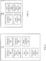
- FIG. 5 is a block diagram illustrating example components of an eNB 106.
- the eNB 106 includes a transceiver component 502, an SPS configuration component 504, a CoMP component 506, and a reference signal component 508.
- the eNB 106 determines and transmits the signals and information as discussed in relation to the UE 102 above.
- the eNB 106 configures the eNB 106 and/or one or more transmission points to transmit the signals and information as discussed above.
- the transceiver component 502 transmits and/or receives information sent between the UE 102 and the eNB 106.
- the transceiver component 502 transmits PDCCH communications to the UE 102 to control a physical communication layer with the UE 102.
- the transceiver component 502 transmits PDSCH communications based on information in the PDCCH communications.
- the transceiver component 502 transmits PDSCH without corresponding PDCCH. For example, following configuration and/or activation of an SPS session, the transceiver component 502 may transmit scheduled PDSCH communications without transmitting corresponding PDCCH communications.
- the SPS configuration component 504 configures the UE 102 for an SPS session.
- the SPS configuration component 504 may send activation information for an SPS session and provide the activation information to the transceiver component 502 for transmission to the UE 102.
- the activation information may include the parameters needed to calculate when a next SPS communication (SPS downlink assignment) will occur.
- the SPS configuration component 504 may also determine additional information to be transmitted to the UE 102 for controlling an SPS session. For example, the SPS configuration component 504 may determine a scrambling identity, a virtual cell identifier, and/or parameter set indicator for use during an SPS session. The SPS configuration component 504 may provide determined values to the transceiver component 502 to be communicated to the UE 102. For example, the scrambling identity, virtual cell identifier, and/or parameter set indicator may be provided to the UE 102 via RRC signaling prior to the beginning and/or during an SPS session.
- the CoMP component 506 configures a transmission mode of the eNB 106 and/or the UE 102 for CoMP transmissions/receptions. In one embodiment, the CoMP component 506 configures the UE 102 for TM10 in LTE so that the UE 102 can receive CoMP transmission. In one embodiment, the CoMP component 506 determines information to be transmitted to another transmission point to allow the eNB 106 and the other transmission point to coordinate to transmit a signal to the UE 102.
- the reference signal component 508 generates a reference signal for transmission by the transceiver component 502 to the UE 102.
- the reference signal component 508 may generate a reference signal based on a scrambling identity and/or a virtual cell identity as discussed above in relation to the reference signal component 406 of the UE 102.
- the reference signal component 508 generates a reference signal based on the same values for a scrambling identity and virtual cell identifier as the UE 102.
- the reference signal component 508 may generate a reference signal with the same reference signal sequence as determined by the reference signal component 406 of the UE 102.
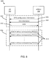
- Figure 6 is a communication timeline 600 illustrating communication between a UE 102 and the one or more eNB(s) 106 during SPS activation/configuration 602 and an during SPS session 604.
- the eNB(s) 106 may include two or more eNBs 106 or transmission points used to coordinate transmission of signals to the UE 102 using CoMP transmission (e.g. using TM10).
- CoMP transmission e.g. using TM10
- TM10 CoMP transmission
- SPS activation/configuration 602 includes the eNB(s) 106 sending 606 SPS configuration information to the UE 102 to configure the UE 102 for an SPS session.
- the configuration information may include downlink SPS configuration information such as a downlink SPS interval and/or a number of HARQ processes.
- DCI is sent 608 to activate SPS on the UE 102 so that the UE is prepared to receive a message on a DL channel.
- the DCI may include a scrambling identity ( n SCID ) and/or a parameter set indicator (PQI).
- the DCI may be sent 608 in a PDCCH communication.
- the DCI may be sent 608 in an SPS activation PDCCH.
- the UE 102 may acknowledge 610 receipt of the SPS configuration information and/or the DCI to confirm that the SPS session 604 will begin.
- the eNB(s) 106 send 612 a plurality of PDSCH without corresponding PDCCH.
- the PDSCH are sent 612 at times indicated by the SPS configuration information and/or based on PDCCH in a subframe where the SPS activated, such as when the DCI 608 was sent 608.
- the PDSCH may be sent 612 at times determined based on equation (5) above.
- the UE 102 receives and/or processes the PDSCH without corresponding PDCCH based on one or more SPS parameters.
- the SPS parameters may be determined based on the DCI sent 606 by the UE 102 during SPS activation/configuration 602, based on values configured through RRC signaling, and/or based on predetermined fixed values for the SPS parameters. For example, a scrambling identity, virtual cell identity, and/or parameter set indicator may be configured in any of the above manners.
- the UE 102 may receive and/or process the PDSCH without corresponding PDCCH based on these parameters.
- Figure 7 is a flow chart illustrating a method 700 for receiving SPS communications.
- the method 700 may be performed by a UE 102 or other wireless mobile device.
- a UE 102 is configured for TM10 during the method 700.
- the transceiver component 402 receives 702 a PDCCH/EPDCCH corresponding to SPS activation.
- the PDCCH/EPDCCH conveys a value for n SCID .
- the PDCCH/EPDCCH conveys a value for n SCID based on DCI format 2D.
- the PDCCH/EPDCCH may include an SPS activation PDCCH/EPDCH.
- the scheduling component 404 configures 704 a DL assignment for receiving SPS PDSCH without a corresponding PDCCH/EPDCCH.
- the DL assignment is configure 704 based on the received 702 PDCCH/EPDCCH corresponding to SPS activation.
- the scheduling component 404 may configure 704 the DL assignment based on the subframe in which the PDCCH/EPDCCH was received and/or based on SPS configuration information transmitted by higher layer signaling.
- the scheduling component 400 configures 704 a DL assignment in a resource element based on equation (5) above.
- the reference signal component 406 generates 706 a reference signal sequence corresponding to the SPS PDSCH.
- the reference signal component 406 generates 706 the reference signal sequence based on the value for n SCID that corresponds to the subframe for SPS activation.
- the value for n SCID may correspond to the value received 702 in the PDCCH/EPDCCH in the SPS activation subframe.
- the signal processing component 412 processes 708 the SPS PDSCH based on the generated reference signal sequence. For example, the signal processing component 412 may process 708 the SPS PDSCH based on a DM-RS with the same sequence as the generated 70 reference signal sequence. Based on processing of the DM-RS, the signal processing component 412 may process 708 the SPS PDSCH to retrieve and/or demodulate data in the SPS PDSCH.
- Figure 8 is a flow chart illustrating a method 800 for receiving SPS communications.
- the method 800 may be performed by a UE 102 or other wireless mobile device.
- a UE 102 is configured for TM10 during the method 800.
- the method 800 begins and the transceiver component 402 receives 802 an SPS activation PDCCH/EPDCCH that conveys a PQI value.
- the SPS activation PDCCH/EPDCCH includes a control communication in which SPS is activated.
- the PDCCH/EPDCCH may include the PQI value based on a DCI format, such as DCI format 2D.
- the PQI value may be used for rate matching in the SPS activation subframe.
- the scheduling component 404 schedules 804 reception of an SPS PDSCH.
- the SPS PDSCH includes a PDSCH without a corresponding PDCCH.
- the scheduling component 404 schedules 804 reception of the SPS PDSCH for one or more resource elements in a later subframe based on equation (5).
- the signal processing component 412 processes 806 the SPS PDSCH based on the PQI value corresponding to SPS activation. For example, the signal processing component 412 may assume that the PQI value for the SPS PDSCH is the same as for SPS activation. Thus, the UE 102 may be able to retrieve data in the SPS PDSCH even though no control signal corresponding to the SPS PDSCH conveying the PQI value was received.
- Figure 9 is a flow chart illustrating a method 900 for providing SPS communications.
- the method 900 may be performed by an eNB 106 or other RNC or transmission point.
- the eNB 106 provides information to a UE 102 based on CoMP during the method 900.
- the CoMP component 506 configures 902 a UE 102 for receiving CoMP transmissions.
- the CoMP component 506 may configure 902 the UE 102 for TM10 so that the UE 102 receives transmissions of the same or similar signal from multiple transmission points.
- the transceiver component 502 transmits 904, in a second subframe, an SPS activation control channel signal.
- the SPS activation control channel signal activates SPS on the UE 102.
- the SPS activation control channel signal may configure the UE 102 to receive SPS shared data channel signals without corresponding control channel signals.
- the SPS activation control channel signal conveys DCI for the UE to receive signals during the subframe where the SPS activation control channel signal was sent.
- PDSCH within the same subframe as SPS activation may be transmitted and/or received based on the DCI in the SPS activation control channel signal.
- the transceiver component 502 transmits 906, during a second subframe, a shared data channel signal without a corresponding control channel signal.
- the transceiver component 502 transmits 906 the shared data channel signal based on SPS configuration information determined by the SPS configuration component 504 and/or the SPS activation control channel signal.
- the SPS configuration information may transmit 908 the shared data channel signal without a corresponding control channel signal in a subframe and or RE determined based on equation (5).
- the eNB 16 reuses parameters in the SPS activation control channel signal for the subframe for the shared data channel signal.
- the transmitted 906 shared data channel signal and/or DM-RS corresponding to the same subframe as the shared data channel signal are transmitted based on one or more of an n SCID and PQI in the SPS activation control channel subframe.
- Figure 10 is a flow chart illustrating a method 800 for receiving SPS communications.
- the method 600 may be performed by a UE 102 or other wireless mobile device.
- the scheduling component 404 schedules 1002 one or more SPS communications based on received SPS activation information.
- the scheduling component 404 may schedule 1002 a PDSCH based on equation (5).
- the SPS communications each include a physical layer data communication without a corresponding physical layer control communication.
- SPS activation information may be received form an eNB 106, another transmission point, or a plurality of eNBs 106 or transmission points.
- the transceiver component 404 receives 1004 an SPS communication.
- the SPS communication may include a physical layer data signal (such as a PDSCH communication) without a corresponding physical layer control signal (such as a PDCCH communication).
- the SPS communication may include a subframe that includes PDSCH information, a reference signal, and/or no PDCCH information.
- the SPS communication includes a communication assigned based on the SPS activation information.
- the initialization component 408 initializes 1006 a scrambling sequence based on a fixed value.
- the fixed value includes a scrambling identity used for all SPS communications.
- the initialization component 408 may initialize 1006 the scrambling initialization sequence based on a fixed value for a virtual cell identifier.
- a value for a virtual cell identifier may be a cell identifier for a serving cell or other cell involved in CoMP transmission to the UE or the virtual cell identifier may include a virtual cell identifier using higher layer signaling (such as RRC layer signaling).
- the reference signal component 406 generates 1008 a reference signal sequence based on the scrambling sequence as initialized 1006 by the initialization component.
- the reference signal sequence generated 1008 by the reference signal component 406 may include a UE-specific reference signal, such as a demodulation reference signal.
- the signal processing component 412 processes 1010 a reference signal of the received 1004 SPS communication based on the generated reference signal sequence. In one embodiment, the signal processing component 412 processes the reference signal for channel estimation or other channel attributes based on the generated reference signal sequence. In one embodiment, the signal processing component 412 may also process 1010 physical layer data signals (such as PDSCH) based on the generated reference signal sequence. For example, the signal processing component 412 may estimate a downlink channel based on the generated reference signal and process a PDSCH based on the channel estimation. The signal processing component 412 may also process 1010 the PDSCH based on a parameter set indicator.
- PDSCH physical layer data signals
- Figure 11 is a flow chart illustrating a method 900 for receiving SPS communications.
- the method 900 may be performed by a UE 102 or other wireless mobile device.
- the scheduling component 404 receives 1102 SPS activation information in a PDSCH communication.
- the scheduling component 404 may configure the UE 102 for SPS by assigning one or more DL resource elements for receipt of an SPS PDSCH communication without a corresponding PDCCH communication based on the SPS activation information.
- the PDSCH communication has a corresponding PDCCH communication for assigning the PDSCH for transmission on the DL channel and for providing DCI configuring the UE 102 to receive the PDSCH.
- the transceiver component 402 receives 1104 an SPS PDSCH communication that does not have a corresponding PDCCH communication.
- the transceiver component 402 may receive 1104 an SPS PDSCH communication that was scheduled for receipt during an SPS session.
- the RRC component 410 receives 1106 one or more DL channel parameters for receiving the SPS PDSCH.
- the RRC component 410 receives 1106 the DL channel parameters including one or more of a scrambling identity, virtual cell identity, and parameter set identifier for receiving and/or processing any SPS PDSCH.
- one or more of the scrambling identity, virtual cell identity, and parameter set identifier may be a predetermined fixed value or a value corresponding to SPS activation.
- the scrambling identity and virtual cell identity may be received 1106 via RRC signaling while the parameter set identifier may have a predetermined fixed value.
- the signal processing component 412 processes 1108 the SPS PDSCH based on the DL channel parameters configured through RRC signaling. For example, the signal processing component 412 may process 1108 the SPS PDSCH based on channel estimation determined from a demodulation reference signal. The channel estimation may be determined based on a scrambling identity configured 1106 through RRC signaling and the signal processing component 412 may process 1108 the SPS PDSCH based on the determined channel estimation. Similarly, the signal processing component 412 may process 1108 the SPS PDSCH based on a parameter set indicator that is configured via RRC signaling, is a predetermined fixed value, or is the same as a value corresponding to SPS activation.
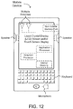
- FIG 11 provides an example illustration of a mobile device, such as a UE, a mobile station (MS), a mobile wireless device, a mobile communication device, a tablet, a handset, or another type of mobile device.
- the mobile device can include one or more antennas configured to communicate with a transmission station, such as a base station (BS), an eNB, a base band unit (BBU), an RRH, a remote radio equipment (RRE), a relay station (RS), a radio equipment, or another type of wireless wide area network (WWAN) access point.
- the mobile device can be configured to communicate using at least one wireless communication standard including 3GPP LTE, WiMAX, High Speed Packet Access (HSPA), Bluetooth, and WiFi.
- the mobile device can communicate using separate antennas for each wireless communication standard or shared antennas for multiple wireless communication standards.
- the mobile device can communicate in a wireless local area network (WLAN), a wireless personal area network (WPAN), and/or a WWAN.
- WLAN wireless local area network
- FIG 11 also provides an illustration of a microphone and one or more speakers that can be used for audio input and output from the mobile device.
- the display screen may be a liquid crystal display (LCD) screen or other type of display screen, such as an organic light emitting diode (OLED) display.
- the display screen can be configured as a touch screen.
- the touch screen may use capacitive, resistive, or another type of touch screen technology.
- An application processor and a graphics processor can be coupled to internal memory to provide processing and display capabilities.
- a non-volatile memory port can also be used to provide data input/output options to a user.
- the non-volatile memory port may also be used to expand the memory capabilities of the mobile device.
- a keyboard may be integrated with the mobile device or wirelessly connected to the mobile device to provide additional user input.
- a virtual keyboard may also be provided using the touch screen.
- the present disclosure provides a method for usage of DM-RS for SPS PDSCH transmission (i.e. PDSCH without PDCCH).
- PDSCH i.e. PDSCH without PDCCH.
- n SCID for DM-RS sequence initialization is given by DCI format 2C.
- Another parameter n ID n SCID is determined by a function of n SCID .
- the parameter n ID i can be used as virtual cell ID having the range of 0 to 503. This can facilitate CoMP operation regardless of physical cell ID.
- a UE can receive the DM-RS from cell B while the serving cell is cell A.
- DCI format 2C or 2D can be used for SPS activation.
- the DCI includes n SCID so that the UE can be aware of the DM-RS sequence initialization value. However, for the following SPS PDSCH transmission, the UE would not know the DM-RS sequence initialization value since there is no PDCCH carrying n SCID .
- a new DCI signaling can be introduced for PQI.
- PQI PQI bit
- a new DCI bit PQI is added to the contents of DCI format 2C to form the DCI format for TM10.
- n ID i n ID DMRS i is used for DM-RS sequence generation and n SCID uses the same one signaled in PDCCH for SPS activation (i.e. by SPS-RNTI or by C-RNTI with SPS-activation validation). And/or, the same PQI can be assumed for PDSCH without the corresponding PDCCH/EPDCCH in a subframe as that given in PDCCH for SPS activation.
- the same parameters of DM-RS for sequence initialization applies in the case that a PDSCH is transmitted without a corresponding PDCCH/EPDCCH.
- the parameter n SCID of PDSCH without a corresponding PDCCH/EPDCCH uses that in PDCCH/EPDCCH for SPS-activation.
- n SCID 0 ⁇ n ID 0 is used in a certain subframe #a
- DM-RS is transmitted from cell#A in subframe#a and DM-RS is transmitted from cell#B in subframe#b.
- the DM-RS sequence in the subframe for SPS activation needs to be same as in the subframe for SPS-PDSCH (i.e. PDSCH without a corresponding PDCCH).
- the same PQI as the serving cell or the cell having n ID cell can be assumed for PDSCH without the corresponding PDCCH/EPDCCH in a subframe.
- n ID i and n SCID are used for DM-RS sequence generation.
- the PQI to be assumed for PDSCH without the corresponding PDCCH/EPDCCH can be predetermined.
- PQI 0, 1, 2, or 3.
- the eNB independently configures ⁇ n SCID ⁇ or ⁇ n SCID and/or n ID i ⁇ for all SPS transmission (including SPS activation). And/or, the PQI to be assumed for PDSCH without the corresponding PDCCH/EPDCCH can be configured by RRC signaling. By doing this, the reception from same TP during a SPS session can be assured.
- n ID i n ID DMRS i is used for DM-RS sequence generation and n SCID uses the same one signaled in PDCCH for SPS-activation (i.e. by SPS-RNTI or by C-RNTI with SPS-activation validation).
- the PQI to be assumed for PDSCH without the corresponding PDCCH/EPDCCH can be predetermined.
- Example 1 is a UE that receives, in a first subframe, a PDCCH/EPDCCH corresponding to SPS activation.
- the PDCCH/EPDCCH conveys a value of n SCID .
- the UE configures, based on the SPS activation, a DL assignment in a second subframe for receivng an SPS PDSCH without a corresponding PDCCH/EPDCCH.
- the UE determines a reference signal sequence corresponding to the SPS PDSCH using n SCID derived from the PDCCH/EPDCCH corresponding to the associated SPS activation.
- the UE receives the SPS PDSCH in a second subframe and processes the SPS PDSCH based on the reference signal sequence for the SPS PDSCH in the second subframe using the n SCID derived from the PDCCH/EPDCCH corresponding to the associated SPS activation.
- the UE is configured for TM10.
- TM10 of Example 1 can optionally include CoMP transmission or reception and one or more of the PDSCH and the PDCCH/EPDCCH comprise CoMP transmissions.
- Example 3 the UE of Examples 1-2 is optionally configured to monitor a DCI format and the value of n SCID is conveyed according to DCI format 2D.
- Example 4 the UE of Examples 1-3 can optionally determine the reference signal sequence by determining the reference signal sequence based on a virtual cell identity of n ID n SCID .
- the virtual cell identity may be selected based on the value for n SCID and may correspond to SPS activation.
- Example 5 the n ID n SCID of Example 4 is configured by signaling on a layer above the physical layer.
- Example 6 the PDCCH/EPDCCH of Examples 1-5 can optionally convey a value for PQI.
- the processing of the SPS PDSCH may include processing based on a transmission parameter set indicated by the value for the PQI.
- Example 7 the UE of Examples 1-6 can optionally process the SPS PDSCH by processing based on a transmission parameter set indicated by a value for PQI configured based on RRC layer signaling.
- Example 8 is a UE that includes a transceiver component, a scheduling component, and a signal processing component.
- the transceiver component is configured to receive, in a first subframe, an SPS activation PDCCH/EPDCCH transmission.
- the SPS activation PDCCH/EPDCCH transmission conveys a value for a PQI.
- the scheduling component is configured to schedule reception of an SPS PDSCH transmission.
- the SPS PDSCH transmission includes a PDSCH transmission without a corresponding PDCCH/EPDCCH transmission.
- the signal processing component is configured to process the SPS PDSCH transmission based on the value for the PQI corresponding to SPS activation.
- the SPS PDSCH is received by the transceiver component during a second subframe and the UE is configured for TM10.
- Example 9 the TM10 of Example 8 includes CoMP transmission or reception and one or more of the SPS PDSCH and the SPS activation PDCCH/EPDCCH comprise CoMP transmissions.
- Example 10 the UE of Examples 8-9 can be optionally configured to monitor a DCI format and wherein the value for the PQI is conveyed according to DCI format 2D.
- Example 11 the SPS activation PDCCH/EPDCCH of Examples 8-10 further conveys a value for a scrambling identity.
- the signal processing component may process the SPS PDSCH based on a reference signal sequence initiated using the value for the scrambling identity.
- Example 12 the UE of Examples 8-11 can optionally include a reference signal component that determines a reference signal sequence based on a scrambling identity and a virtual cell identity.
- Example 13 the UE of Examples 8-12 can optionally include an RRC component configured to configure one or more of the scrambling identity and the virtual cell identity using RRC layer signaling.
- Example 14 is an eNB that configures a UE for CoMP transmission.
- the eNB transmits, in a first subframe, an SPS activation control channel signal.
- the SPS activation control channel signal conveys DCI for the UE to receive signals in the first subframe.
- the eNB transmits a shared data channel signal without a corresponding control channel signal based on the DCI corresponding to the SPS activation control channel signal.
- the shared data channel signal is transmitted in a second subframe.
- Example 15 the DCI of Example 14 conveys one or more of a scrambling identity (n SCID ) and a PQI based on format 2D.
- the shared data channel signal is transmitted based on one or more of the n SCID and the PQI.
- Example 16 is a mobile wireless device that includes a transceiver component, an initialization component, a reference signal component, and a signal processing component.
- the transceiver component is configured to receive a scheduled communication on a shared channel without a corresponding control communication on a control channel.
- the scheduled communication comprises a CoMP transmission.
- the initialization component is configured to initialize a pseudo-random sequence based on a scrambling identity.
- the scrambling identity includes a predetermined fixed value.
- the reference signal component is configured to determine a reference signal sequence based on the pseudo-random sequence.
- the signal processing component is configured to process a demodulation reference signal corresponding to the scheduled communication based on the determined reference signal sequence.
- Example 17 initializing the pseudo-random sequence in Example 16 is optionally further based on a cell identifier of a serving cell.
- initializing the pseudo-random sequence in Example 16 optionally is further based on a virtual cell identifier.
- the virtual cell identifier includes a predetermined fixed value for scheduled communications.
- Example 19 the pseudo-random sequence of Example 16 is optionally initialized based on a virtual cell identifier configured by higher layer signaling.
- receiving the scheduled communication in Examples 16-19 optionally include receiving based on a parameter set indicator that indicates a transmission parameter set for receiving a signal from a serving transmission point.
- the parameter set indicator includes a predetermined fixed value for scheduled communications.
- processing the demodulation reference signal in Examples 16-20 optionally includes estimating a channel (channel estimation) for the demodulation reference signal.
- the signal processing component can optionaly process the scheduled communication based on the channel estimation.
- Example 22 is a method for an SPS process.
- the method includes receiving, in a first subframe, a PDCCH/EPDCCH corresponding to SPS activation.
- the PDCCH/EPDCCH conveys a value of n SCID .
- the method includes configuring, based on the SPS activation, a DL assignment in a second subframe for receivng an SPS PDSCH without a corresponding PDCCH/EPDCCH.
- the method further includes determines a reference signal sequence corresponding to the SPS PDSCH using n SCID derived from the PDCCH/EPDCCH corresponding to the associated SPS activation.
- the method further includes receiving the SPS PDSCH in a second subframe and processes the SPS PDSCH based on the reference signal sequence for the SPS PDSCH in the second subframe using the n SCID derived from the PDCCH/EPDCCH corresponding to the associated SPS activation.
- the UE is configured for TM10.
- TM10 of Example 22 can optionally include CoMP transmission or reception and one or more of the PDSCH and the PDCCH/EPDCCH comprise CoMP transmissions.
- Example 24 the method of Examples 22-23 can optionally include monitoring a DCI format and the value of n SCID is conveyed according to DCI format 2D.
- Example 25 the method of Examples 22-24 can optionally include determining the reference signal sequence by determining the reference signal sequence based on a virtual cell identity of n ID n SCID .
- the virtual cell identity may be selected based on the value for n SCID and may correspond to SPS activation.
- Example 26 the n ID n SCID of Example 25 is configured by signaling on a layer above the physical layer.
- Example 27 the PDCCH/EPDCCH of Examples 22-26 can optionally convey a value for PQI.
- the processing of the SPS PDSCH may include processing based on a transmission parameter set indicated by the value for the PQI.
- Example 28 the method of Examples 22-27 can optionally include processing the SPS PDSCH by processing based on a transmission parameter set indicated by a value for PQI configured based on RRC layer signaling.
- Example 29 a method for an SPS process includes receiving, in a first subframe, an SPS activation PDCCH/EPDCCH transmission.
- the SPS activation PDCCH/EPDCCH transmission conveys a value for a PQI.
- the method includes scheduling reception of an SPS PDSCH transmission.
- the SPS PDSCH transmission includes a PDSCH transmission without a corresponding PDCCH/EPDCCH transmission.
- the method includes processing the SPS PDSCH transmission based on the value for the PQI corresponding to SPS activation.
- the SPS PDSCH is received during a second subframe and the UE is configured for TM10.
- Example 30 the TM10 of Example 29 includes CoMP transmission or reception and one or more of the SPS PDSCH and the SPS activation PDCCH/EPDCCH comprise CoMP transmissions.
- Example 31 the method of Examples 29-30 can optionally includee monitoring a DCI format and wherein the value for the PQI is conveyed according to DCI format 2D.
- Example 32 the SPS activation PDCCH/EPDCCH of Examples 29-31 further conveys a value for a scrambling identity.
- the method may include processing the SPS PDSCH based on a reference signal sequence initiated using the value for the scrambling identity.
- Example 33 the method of Examples 29-32 can optionally include determining a reference signal sequence based on a scrambling identity and a virtual cell identity.
- Example 34 the method of Examples 29-33 can optionally include configuring one or more of the scrambling identity and the virtual cell identity using RRC layer signaling.
- Example 35 is a method for an SPS process that includes configuring a UE for CoMP transmission.
- the method includes transmitting, in a first subframe, an SPS activation control channel signal.
- the SPS activation control channel signal conveys DCI for the UE to receive signals in the first subframe.
- the method includes transmitting a shared data channel signal without a corresponding control channel signal based on the DCI corresponding to the SPS activation control channel signal.
- the shared data channel signal is transmitted in a second subframe.
- Example 36 the DCI of Example 35 conveys one or more of a scrambling identity (n SCID ) and a PQI based on format 2D.
- the shared data channel signal is transmitted based on one or more of the n SCID and the PQI.
- Example 37 is a method for an SPS process that includes receiving a scheduled communication on a shared channel without a corresponding control communication on a control channel.
- the scheduled communication comprises a CoMP transmission.
- the method includes initializing a pseudo-random sequence based on a scrambling identity.
- the scrambling identity includes a predetermined fixed value.
- the method includes determining a reference signal sequence based on the pseudo-random sequence.
- the method further includes processing a demodulation reference signal corresponding to the scheduled communication based on the determined reference signal sequence.
- Example 38 initializing the pseudo-random sequence in Example 39 is optionally further based on a cell identifier of a serving cell.
- initializing the pseudo-random sequence in Example 39 optionally is further based on a virtual cell identifier.
- the virtual cell identifier includes a predetermined fixed value for scheduled communications.
- Example 40 the pseudo-random sequence of Example 39 is optionally initialized based on a virtual cell identifier configured by higher layer signaling.
- receiving the scheduled communication in Examples 37-40 can optionally include receiving based on a parameter set indicator that indicates a transmission parameter set for receiving a signal from a serving transmission point.
- the parameter set indicator includes a predetermined fixed value for scheduled communications.
- processing the demodulation reference signal in Examples 37-41 optionally includes estimating a channel (channel estimation) for the demodulation reference signal.
- the signal processing component can optionally process the scheduled communication based on the channel estimation.
- Example 43 is an apparatus comprising means to perform a method of any of Examples 22-42.
- Example 44 is a machine readable storage including machine-readable instructions, when executed, to implement a method or realize an apparatus of any of Examples 27-43.
- Example 45 is a User equipment (UE) configured to receive, in a first subframe, a physical downlink control channel or enhanced physical downlink control channel (PDCCH/EPDCCH) corresponding to semi-persistent scheduling (SPS) activation, wherein the PDCCH/EPDCCH conveys a value of nSCID; configure, based on the SPS activation, a downlink (DL) assignment in a second subframe; receive, in the second subframe, an SPS physical downlink shared channel (PDSCH) without a corresponding PDCCH/EPDCCH; determine a reference signal sequence corresponding to the SPS PDSCH using the value of nSCID derived from the PDCCH/EPDCCH corresponding to the associated SPS activation; and process the SPS PDSCH based on the reference signal sequence determined using the value of nSCID derived from the PDCCH/EPDCCH corresponding to the associated SPS activation.
- UE User equipment
- Example 46 is the UE of Example 45, wherein the UE is configured for transmission mode 10 (TM10) for coordinated multipoint (CoMP) transmission or reception, and wherein one or more of the PDSCH and the PDCCH/EPDCCH corresponding to the associated SPS activation comprise CoMP transmissions.
- TM10 transmission mode 10
- CoMP coordinated multipoint
- Example 47 is the UE of Example 45, wherein the UE is further configured to monitor a downlink control information (DCI) format and wherein the value of nSCID is conveyed according to DCI format 2D.
- DCI downlink control information
- Example 48 is the UE of Example 45, wherein to determine the reference signal sequence, the UE is configured to generate the reference signal sequence based on a virtual cell identity of n ID n SCID selected based on the value for nSCID, the virtual cell identity corresponding to the SPS activation.
- Example 49 is the UE of Example 48, wherein the n ID n SCID is configured by signaling on a layer above the physical layer.
- Example 50 is the UE of Example 45, wherein the PDCCH/EPDCCH corresponding to the associated SPS activation further conveys a value for a PDSCH resource element (RE) mapping quasi co-location indicator (PQI), and wherein the UE is further configured to process the SPS PDSCH based on a transmission parameter set indicated by the value for the PQI.
- the PDCCH/EPDCCH corresponding to the associated SPS activation further conveys a value for a PDSCH resource element (RE) mapping quasi co-location indicator (PQI)
- the UE is further configured to process the SPS PDSCH based on a transmission parameter set indicated by the value for the PQI.
- RE resource element
- Example 51 is the UE of Example 45, wherein the UE is further configured to process the SPS PDSCH based on a transmission parameter set indicated by a value for a PDSCH resource element (RE) mapping quasi co-location indicator (PQI), wherein the value for the PQI is configured based on RRC layer signaling.
- RE resource element
- PQI quasi co-location indicator
- Example 52 is a User equipment (UE) comprising a transceiver component configured to receive a semi-persistent scheduling (SPS) activation physical downlink control channel or enhanced physical downlink control channel (PDCCH/EPDCCH) transmission, wherein the SPS activation PDCCH/EPDCCH transmission conveys a value for a physical downlink shared channel (PDSCH) resource element (RE) mapping and quasi co-location indicator (PQI); a scheduling component configured to schedule reception of an SPS PDSCH transmission, the SPS PDSCH transmission comprising a PDSCH transmission without a corresponding PDCCH/EPDCCH transmission; and a signal processing component configured to process the SPS PDSCH transmission based on the value for the PQI corresponding to SPS activation, wherein the SPS PDSCH is received by the transceiver component, and wherein the UE is configured for transmission mode 10 (TM10).
- SPS semi-persistent scheduling
- PDCCH/EPDCCH enhanced physical downlink control channel
- TM10 transmission
- Example 53 is the UE of Example 52, wherein TM10 is configured for coordinated multipoint (CoMP) transmission or reception and wherein one or more of the SPS PDSCH and the SPS activation PDCCH/EPDCCH comprise CoMP transmissions.
- TM10 is configured for coordinated multipoint (CoMP) transmission or reception and wherein one or more of the SPS PDSCH and the SPS activation PDCCH/EPDCCH comprise CoMP transmissions.
- CoMP coordinated multipoint
- Example 54 is the UE of Example 52, wherein the UE is configured to monitor a downlink control information (DCI) format and wherein the value for the PQI is conveyed according to DCI format 2D.
- DCI downlink control information
- Example 55 is the UE of Example 52, wherein the SPS activation PDCCH/EPDCCH further conveys a value for a scrambling identity and wherein the signal processing component processes the SPS PDSCH based on a reference signal sequence initiated using the value for the scrambling identity.
- Example 56 is the UE of Example 52, further comprising a reference signal component that determines a reference signal sequence based on a scrambling identity and a virtual cell identity, and further comprising a radio resource configuration (RRC) component configured to configure one or more of the scrambling identity and the virtual cell identity using RRC layer signaling.
- RRC radio resource configuration
- Example 57 is an evolved universal terrestrial radio access network (E-UTRAN) node B (eNB) configured to configure user equipment (UE) for coordinated multi-point (CoMP) transmission; transmit, in a first subframe, a semi-persistent scheduling (SPS) activation control channel signal, wherein the SPS activation control channel signal conveys downlink control information (DCI) for the UE to receive signals in the first subframe; and transmit a shared data channel signal without a corresponding control channel signal based on the DCI corresponding to the SPS activation control channel signal, wherein the shared data channel signal is transmitted in a second subframe.
- E-UTRAN evolved universal terrestrial radio access network
- eNB evolved universal terrestrial radio access network
- UE user equipment
- CoMP coordinated multi-point
- Example 58 is the eNB of Example 57, wherein the DCI conveys one or more of a scrambling identity (nSCID) and a physical downlink shared channel (PDSCH) resource element (RE) mapping and quasi co-location indicator (PQI) based on format 2D and wherein the shared data channel signal is transmitted based on one or more of the nSCID and the PQI.
- nSCID scrambling identity
- PDSCH physical downlink shared channel
- RE resource element mapping and quasi co-location indicator
- PQI quasi co-location indicator
- Example 59 is a mobile wireless device comprising a transceiver component configured to receive a scheduled communication on a shared channel without a corresponding control communication on a control channel, wherein the scheduled communication comprises a coordinated multipoint transmission; an initialization component configured to initialize a pseudo-random sequence based on a scrambling identity, the scrambling identity comprising a predetermined fixed value; a reference signal component configured to determine a reference signal sequence based on the pseudo-random sequence; and a signal processing component configured to process a demodulation reference signal corresponding to the scheduled communication based on the determined reference signal sequence.
- Example 60 is the mobile wireless device of Example 59, wherein initializing the pseudo-random sequence is further based on a cell identifier of a serving cell.
- Example 61 is the mobile wireless device of Example 59, wherein initializing the pseudo-random sequence is further based on a virtual cell identifier, the virtual cell identifier comprising a predetermined fixed value for scheduled communications.
- Example 62 is the mobile wireless device of Example 59, wherein the pseudo-random sequence is initialized based on a predetermined virtual cell identifier.
- Example 63 is the mobile wireless device of Example 59, wherein receiving the scheduled communication comprises receiving based on a parameter set indicator that indicates a transmission parameter set for receiving a signal from a serving transmission point, wherein the parameter set indicator comprises a predetermined fixed value for scheduled communications.
- Example 64 is the mobile wireless device of Example 59, wherein processing the demodulation reference signal comprises estimating a channel (channel estimation) for the demodulation reference signal and wherein the signal processing component further processes the scheduled communication based on the channel estimation.
- ASICs application-specific integrated circuits
- PLDs programmable logic devices
- FPGAs field-programmable gate arrays
- Machine-readable medium includes any mechanism that can store information in a form that is accessible by a machine (a machine may be, for example, a computer, a network device, a cellular phone, a PDA, a manufacturing tool, any device with one or more processors, etc.).
- a machine-accessible medium includes recordable/non-recordable media (e.g., read-only memory (ROM), random access memory (RAM), magnetic disk storage media, optical storage media, flash memory devices, etc.).
- logic can include, for example, special-purpose hardwired circuitry, software and/or firmware in conjunction with programmable circuitry, or a combination thereof.
- Various techniques, or certain aspects or portions thereof, may take the form of program code (i.e., instructions) embodied in tangible media, such as floppy diskettes, CD-ROMs, hard drives, a non-transitory computer readable storage medium, or any other machine-readable storage medium wherein, when the program code is loaded into and executed by a machine, such as a computer, the machine becomes an apparatus for practicing the various techniques.
- the computing device may include a processor, a storage medium readable by the processor (including volatile and non-volatile memory and/or storage elements), at least one input device, and at least one output device.
- the volatile and non-volatile memory and/or storage elements may be a RAM, EPROM, flash drive, optical drive, magnetic hard drive, or other medium for storing electronic data.
- the eNodeB (or other base station) and UE (or other mobile station) may also include a transceiver component, a counter component, a processing component, and/or a clock component or timer component.
- One or more programs that may implement or utilize the various techniques described herein may use an application programming interface (API), reusable controls, and the like. Such programs may be implemented in a high level procedural or object oriented programming language to communicate with a computer system. However, the program(s) may be implemented in assembly or machine language, if desired. In any case, the language may be a compiled or interpreted language, and combined with hardware implementations.
- API application programming interface
- a component may be implemented as a hardware circuit comprising custom VLSI circuits or gate arrays, off-the-shelf semiconductors such as logic chips, transistors, or other discrete components.
- a component may also be implemented in programmable hardware devices such as field programmable gate arrays, programmable array logic, programmable logic devices, or the like.
- Components may also be implemented in software for execution by various types of processors.
- An identified component of executable code may, for instance, comprise one or more physical or logical blocks of computer instructions, which may, for instance, be organized as an object, procedure, or function. Nevertheless, the executables of an identified component need not be physically located together, but may comprise disparate instructions stored in different locations which, when joined logically together, comprise the component and achieve the stated purpose for the component.
- a component of executable code may be a single instruction, or many instructions, and may even be distributed over several different code segments, among different programs, and across several memory devices.
- operational data may be identified and illustrated herein within components, and may be embodied in any suitable form and organized within any suitable type of data structure. The operational data may be collected as a single data set, or may be distributed over different locations including over different storage devices, and may exist, at least partially, merely as electronic signals on a system or network.
- the components may be passive or active, including agents operable to perform desired functions.
Landscapes
- Engineering & Computer Science (AREA)
- Signal Processing (AREA)
- Computer Networks & Wireless Communication (AREA)
- Quality & Reliability (AREA)
- Databases & Information Systems (AREA)
- Mobile Radio Communication Systems (AREA)
Applications Claiming Priority (5)
| Application Number | Priority Date | Filing Date | Title |
|---|---|---|---|
| US201261707784P | 2012-09-28 | 2012-09-28 | |
| US201261721436P | 2012-11-01 | 2012-11-01 | |
| US13/928,722 US9973315B2 (en) | 2012-09-28 | 2013-06-27 | Systems and methods for semi-persistent scheduling of wireless communications |
| PCT/US2013/061761 WO2014052499A1 (fr) | 2012-09-28 | 2013-09-25 | Systèmes et procédés pour une programmation semi-persistante de communications sans fil |
| EP13841098.0A EP2901788B1 (fr) | 2012-09-28 | 2013-09-25 | Systèmes et procédés pour une programmation semi-persistante de communications sans fil |
Related Parent Applications (2)
| Application Number | Title | Priority Date | Filing Date |
|---|---|---|---|
| EP13841098.0A Division EP2901788B1 (fr) | 2012-09-28 | 2013-09-25 | Systèmes et procédés pour une programmation semi-persistante de communications sans fil |
| EP13841098.0A Division-Into EP2901788B1 (fr) | 2012-09-28 | 2013-09-25 | Systèmes et procédés pour une programmation semi-persistante de communications sans fil |
Publications (3)
| Publication Number | Publication Date |
|---|---|
| EP3316643A2 true EP3316643A2 (fr) | 2018-05-02 |
| EP3316643A3 EP3316643A3 (fr) | 2018-08-29 |
| EP3316643B1 EP3316643B1 (fr) | 2019-09-04 |
Family
ID=50385115
Family Applications (2)
| Application Number | Title | Priority Date | Filing Date |
|---|---|---|---|
| EP17196578.3A Active EP3316643B1 (fr) | 2012-09-28 | 2013-09-25 | Systèmes et procédés de programmation semi-persistante de communications sans fil |
| EP13841098.0A Active EP2901788B1 (fr) | 2012-09-28 | 2013-09-25 | Systèmes et procédés pour une programmation semi-persistante de communications sans fil |
Family Applications After (1)
| Application Number | Title | Priority Date | Filing Date |
|---|---|---|---|
| EP13841098.0A Active EP2901788B1 (fr) | 2012-09-28 | 2013-09-25 | Systèmes et procédés pour une programmation semi-persistante de communications sans fil |
Country Status (14)
| Country | Link |
|---|---|
| US (2) | US9973315B2 (fr) |
| EP (2) | EP3316643B1 (fr) |
| JP (3) | JP2015532822A (fr) |
| KR (3) | KR101786435B1 (fr) |
| CN (2) | CN109246807B (fr) |
| AU (3) | AU2013323624B2 (fr) |
| BR (2) | BR122022013196B1 (fr) |
| CA (1) | CA2882353C (fr) |
| ES (1) | ES2656900T3 (fr) |
| HK (1) | HK1210353A1 (fr) |
| HU (1) | HUE036442T2 (fr) |
| MX (2) | MX351625B (fr) |
| MY (1) | MY172884A (fr) |
| WO (1) | WO2014052499A1 (fr) |
Families Citing this family (76)
| Publication number | Priority date | Publication date | Assignee | Title |
|---|---|---|---|---|
| US8948097B2 (en) * | 2009-09-30 | 2015-02-03 | Qualcomm Incorporated | UE-RS sequence initialization for wireless communication systems |
| US8923905B2 (en) | 2009-09-30 | 2014-12-30 | Qualcomm Incorporated | Scrambling sequence initialization for coordinated multi-point transmissions |
| US9432164B2 (en) | 2009-10-15 | 2016-08-30 | Qualcomm Incorporated | Method and apparatus for reference signal sequence mapping in wireless communication |
| JP5271373B2 (ja) * | 2011-03-24 | 2013-08-21 | シャープ株式会社 | 基地局、端末、通信システム、通信方法、および集積回路 |
| KR102186240B1 (ko) * | 2012-08-31 | 2020-12-03 | 엘지전자 주식회사 | 무선 통신 시스템에서 하향링크 신호 수신 방법 및 장치 |
| EP2903174B1 (fr) * | 2012-09-27 | 2019-11-13 | Electronics and Telecommunications Research Institute | Procédé de signalisation d'informations de commande pour transmission coordonnée multipoint dans un système de communication sans fil |
| US9973315B2 (en) | 2012-09-28 | 2018-05-15 | Intel Corporation | Systems and methods for semi-persistent scheduling of wireless communications |
| CN107872257B (zh) * | 2012-10-04 | 2021-03-16 | Lg 电子株式会社 | 在无线通信系统中通过考虑天线端口关系收发下行链路信号的方法和设备 |
| EP2905915B1 (fr) * | 2012-10-04 | 2018-09-12 | LG Electronics Inc. | Procédé et appareil de réception de pdsch |
| CN104737479B (zh) | 2012-10-18 | 2018-07-06 | Lg电子株式会社 | 通信系统中接收或发送下行链路控制信号的方法及设备 |
| KR102086518B1 (ko) * | 2012-10-25 | 2020-03-09 | 엘지전자 주식회사 | 무선 통신 시스템에서 하향링크 신호 송수신 방법 및 이를 위한 장치 |
| US11139862B2 (en) * | 2012-11-02 | 2021-10-05 | Samsung Electronics Co., Ltd. | Configuration of rate matching and interference measurement resources for coordinated multi-point transmission |
| US9572159B2 (en) * | 2012-11-09 | 2017-02-14 | Sharp Kabushiki Kaisha | Terminal device, communication method and integrated circuit |
| US9635657B2 (en) | 2012-12-21 | 2017-04-25 | Blackberry Limited | Resource scheduling in direct device to device communications systems |
| US9699589B2 (en) | 2012-12-21 | 2017-07-04 | Blackberry Limited | Managing sessions for direct device to device communications |
| US9271302B2 (en) | 2012-12-21 | 2016-02-23 | Blackberry Limited | Network-managed direct device to device communications |
| US9295044B2 (en) * | 2012-12-21 | 2016-03-22 | Blackberry Limited | Resource scheduling in direct device to device communications systems |
| CN104904150B (zh) | 2013-01-07 | 2018-01-16 | Lg电子株式会社 | 发送/接收信号的方法和设备 |
| US11005613B2 (en) * | 2013-01-24 | 2021-05-11 | Qualcomm Incorporated | Multiple power control and timing advance loops during wireless communication |
| US10263741B2 (en) * | 2013-05-10 | 2019-04-16 | Qualcomm Incorporated | Coordinated multipoint (CoMP) and network assisted interference suppression/cancellation |
| EP3021629B1 (fr) * | 2013-07-11 | 2021-03-10 | Sharp Kabushiki Kaisha | Appareil terminal, appareil station de base et procédés de communication pour transmettre et recevoir des signaux de référence |
| US20150085796A1 (en) * | 2013-09-20 | 2015-03-26 | Qualcomm Incorporated | Flexible operation of enhanced tti-bundling modes in lte |
| US9462627B2 (en) | 2013-09-25 | 2016-10-04 | Apple Inc. | Uplink and downlink semi-persistent scheduling alignment |
| CN104683990B (zh) * | 2013-11-28 | 2019-04-05 | 北京信威通信技术股份有限公司 | 一种无线覆盖的方法、装置和系统 |
| US10256855B2 (en) * | 2014-01-31 | 2019-04-09 | Qualcomm Incorporated | Interference management information signaling |
| WO2015180175A1 (fr) * | 2014-05-30 | 2015-12-03 | 华为技术有限公司 | Procédé et dispositif pour envoyer et recevoir des informations de commande de liaison descendante |
| JP6688745B2 (ja) * | 2015-01-30 | 2020-04-28 | 京セラ株式会社 | 基地局及びユーザ端末 |
| CN107852205B (zh) * | 2015-08-12 | 2021-06-04 | 苹果公司 | 多用户多输入多输出通信系统和方法 |
| US10285168B2 (en) * | 2015-09-16 | 2019-05-07 | Intel Corporation | Systems and methods for elimination of PDCCH in resource allocation signaling for MTC devices |
| US9832747B2 (en) | 2015-09-21 | 2017-11-28 | Intel IP Corporation | Mobile terminal device, mobile processing circuit and method of processing signals |
| WO2017052170A1 (fr) * | 2015-09-21 | 2017-03-30 | Lg Electronics Inc. | Procédé de gestion d'une retransmission adaptative dans un système de communication sans fil et dispositif afférent |
| US10158464B2 (en) | 2015-09-25 | 2018-12-18 | Intel IP Corporation | Mobile terminal devices, mobile processing circuits, and methods of processing signals |
| US11277235B2 (en) * | 2015-11-23 | 2022-03-15 | Qualcomm Incorporated | Techniques for multiplexing or cascading control information and data within a transmission time interval |
| WO2017095470A1 (fr) * | 2015-12-02 | 2017-06-08 | Intel IP Corporation | Système et procédé de conception d'indicateur de commande de liaison descendante dans un système d'agrégation de faisceaux |
| EP4167673A1 (fr) * | 2016-02-03 | 2023-04-19 | LG Electronics Inc. | Procédé et appareil pour effectuer une activation de planification semi-persistante déclenchée par un équipement utilisateur dans un système de communication sans fil |
| WO2017138772A2 (fr) * | 2016-02-12 | 2017-08-17 | 엘지전자 주식회사 | Procédé d'émission et de réception de signaux entre une station de base et un terminal dans un système de communication sans fil, et dispositif le prenant en charge |
| WO2017171923A1 (fr) * | 2016-04-01 | 2017-10-05 | Intel Corporation | Configuration de communication v2x sur la base d'un emplacement géographique |
| US10349440B2 (en) * | 2016-04-11 | 2019-07-09 | Qualcomm Incorporated | Feedback mechanism to activate and/or deactivate a semi-persistent scheduling grant |
| EP3455970B1 (fr) * | 2016-05-12 | 2022-09-28 | Apple Inc. | Systèmes, procédés et dispositifs de retransmission non adaptative utilisant des ressources de programmation semi-persistantes |
| US10462739B2 (en) | 2016-06-21 | 2019-10-29 | Samsung Electronics Co., Ltd. | Transmissions of physical downlink control channels in a communication system |
| WO2018031816A1 (fr) * | 2016-08-10 | 2018-02-15 | Ofinno Technologies, Llc | Configuration de programmation semi-persistante, et communications v2x, dans un réseau sans fil |
| TWI683561B (zh) | 2016-08-11 | 2020-01-21 | 弗勞恩霍夫爾協會 | 用於潛時受限及可靠之無線通訊系統之排程增強技術 |
| EP3487230B1 (fr) * | 2016-08-12 | 2021-06-09 | Huawei Technologies Co., Ltd. | L'envoi et la réception d'informations programmes de la liaison montante |
| KR102684277B1 (ko) * | 2016-08-24 | 2024-07-11 | 삼성전자 주식회사 | 이동 통신 시스템에서의 기준 신호 송신을 위한 방법 및 장치 |
| WO2018038556A1 (fr) | 2016-08-24 | 2018-03-01 | 삼성전자 주식회사 | Procédé et appareil permettant d'émettre un signal de référence dans un système de communication mobile |
| CN110401521B (zh) * | 2016-09-30 | 2020-11-06 | 中兴通讯股份有限公司 | 表征准共位置参数配置的方法和装置、发射及接收设备 |
| US20180132223A1 (en) * | 2016-11-04 | 2018-05-10 | Qualcomm Incorporated | Techniques for configuring reference signal patterns in wireless communications |
| US10333595B2 (en) * | 2017-02-21 | 2019-06-25 | Qualcomm Incorporated | Reference signal and Tx/Rx precoding for UE multiplexing in NR SS |
| CN109391445B (zh) | 2017-08-11 | 2021-08-20 | 华为技术有限公司 | 一种pdsch接收信息的指示方法、数据接收方法及装置 |
| CN118201100A (zh) * | 2017-09-28 | 2024-06-14 | 三星电子株式会社 | 用于在多个带宽部分上执行数据发射和测量的方法和网络节点 |
| US11025372B2 (en) | 2017-10-26 | 2021-06-01 | Qualcomm Incorporated | Semi-persistent scheduling management in new radio |
| WO2019098892A1 (fr) | 2017-11-14 | 2019-05-23 | Telefonaktiebolaget Lm Ericsson (Publ) | Processus de signalisation d'accusé de réception de réseaux d'accès radio |
| US11290957B2 (en) * | 2017-11-17 | 2022-03-29 | Samsung Electronics Co., Ltd. | Sequence design of wake-up signals and resynchronization sequence |
| US10924245B2 (en) * | 2017-12-06 | 2021-02-16 | Qualcomm Incorporated | DMRS design for SPS assigned traffic |
| US10897766B2 (en) * | 2018-01-12 | 2021-01-19 | Telefonaktiebolaget Lm Ericsson (Publ) | Scrambling of physical channels and reference signals in wireless communication networks |
| US11356311B2 (en) | 2018-01-12 | 2022-06-07 | Telefonaktiebolaget Lm Ericsson (Publ) | Scrambling of physical channels and reference signals in wireless communication networks |
| WO2019157761A1 (fr) * | 2018-02-15 | 2019-08-22 | Qualcomm Incorporated | Techniques d'activation de configuration semi-persistante pour ensembles de ressources d'indicateur d'état de canal |
| WO2019193727A1 (fr) * | 2018-04-05 | 2019-10-10 | 株式会社Nttドコモ | Dispositif utilisateur |
| CN110380834B (zh) | 2018-04-13 | 2022-02-22 | 华硕电脑股份有限公司 | 无线通信系统中用于数据传送的波束指示的方法和设备 |
| WO2019206432A1 (fr) * | 2018-04-27 | 2019-10-31 | Telefonaktiebolaget Lm Ericsson (Publ) | Technique de brouillage de signaux de référence |
| TWI708517B (zh) * | 2018-05-06 | 2020-10-21 | 南韓商Lg電子股份有限公司 | 用於傳輸和接收下行鏈路資料的方法及裝置 |
| US11523419B2 (en) * | 2018-06-18 | 2022-12-06 | Ntt Docomo, Inc. | User terminal |
| CN112840612B (zh) * | 2018-08-09 | 2024-03-01 | 株式会社Ntt都科摩 | 终端、无线通信方法、基站以及系统 |
| CN112771960A (zh) * | 2018-09-26 | 2021-05-07 | 苹果公司 | 用于半持久调度(sps)数据传输的增强型混合自动重传请求(harq) |
| CN113315618B (zh) * | 2018-11-01 | 2022-10-11 | Oppo广东移动通信有限公司 | 一种数据加扰方法及装置、通信设备 |
| WO2020145800A1 (fr) * | 2019-01-11 | 2020-07-16 | 엘지전자 주식회사 | Procédé de transmission/réception de données dans un système de communication sans fil, et dispositif associé |
| US11546911B2 (en) | 2019-01-24 | 2023-01-03 | Qualcomm Incorporated | Enhancements to support multiple semi-persistent resource allocations per serving cell |
| US11652526B2 (en) * | 2019-04-30 | 2023-05-16 | Ofinno, Llc | Channel state information feedback for multiple transmission reception points |
| US11350419B2 (en) * | 2019-06-28 | 2022-05-31 | Qualcomm Incorporated | Semi-persistent scheduling (SPS) for multi-DCI based multi-transmitter receiver point (TRP) |
| WO2021026903A1 (fr) * | 2019-08-15 | 2021-02-18 | 富士通株式会社 | Procédé et appareil d'envoi de signal, procédé et appareil de réception de signal et système de communication |
| CN112804033B (zh) * | 2019-11-14 | 2023-05-26 | 维沃移动通信有限公司 | 一种harq-ack处理方法及相关设备 |
| KR102534482B1 (ko) * | 2020-04-27 | 2023-05-26 | 엘지전자 주식회사 | 하향링크 채널을 수신하는 방법, 사용자기기, 프로세싱 장치, 저장 매체 및 컴퓨터 프로그램, 그리고 하향링크 채널을 전송하는 방법 및 기지국 |
| US11825321B2 (en) * | 2020-09-23 | 2023-11-21 | Qualcomm Incorporated | Beam failure detection using mixed downlink reference signal |
| US11956798B2 (en) * | 2020-10-19 | 2024-04-09 | Samsung Electronics Co., Ltd. | Method and apparatus for grant-free data transmission in wireless communication system |
| US20220124775A1 (en) * | 2020-10-20 | 2022-04-21 | Samsung Electronics Co., Ltd. | Method and device for uplink transmission |
| WO2022265626A1 (fr) * | 2021-06-15 | 2022-12-22 | Zeku, Inc. | Appareil et procédé d'économie d'énergie pour équipement utilisateur lors d'une transmission à programmation semi-persistante |
Family Cites Families (36)
| Publication number | Priority date | Publication date | Assignee | Title |
|---|---|---|---|---|
| KR101192625B1 (ko) | 2008-03-20 | 2012-10-18 | 노키아 코포레이션 | 모바일 통신 시스템에서 반영구적으로 할당된 패킷 전송 자원들에 대한 새 데이터 표시자 플래그 |
| US8520747B2 (en) | 2008-03-20 | 2013-08-27 | Qualcomm Incorporated | Channel estimation in wireless systems with impulsive interference |
| CN101646239B (zh) | 2008-08-06 | 2012-05-09 | 中兴通讯股份有限公司 | 一种半持久调度的方法 |
| US8649320B2 (en) * | 2008-09-22 | 2014-02-11 | Htc Corporation | Method and related device of scheduling request behavior in a wireless communication system |
| CN101790150B (zh) | 2009-01-23 | 2012-01-25 | 华为技术有限公司 | 一种更新接入点名称签约配置的方法及装置 |
| US8537724B2 (en) * | 2009-03-17 | 2013-09-17 | Motorola Mobility Llc | Relay operation in a wireless communication system |
| EP2424126B1 (fr) | 2009-04-22 | 2017-07-05 | LG Electronics Inc. | Procédé et appareil de transmission d'un signal de référence dans un système de communication par relais |
| KR101663616B1 (ko) * | 2009-04-29 | 2016-10-07 | 엘지전자 주식회사 | 다중 안테나 무선 통신 시스템에서 참조 신호 시퀀스 생성 방법 및 이를 위한 장치 |
| US8260356B2 (en) | 2009-06-18 | 2012-09-04 | Samsung Electronics Co., Ltd. | Method and system for indicating method used to scramble dedicated reference signals |
| EP2465317B1 (fr) | 2009-08-14 | 2014-08-06 | BlackBerry Limited | Structure de trame et signalisation de commande pour une transmission multipoint coordonnée (comp) de liaison descendante |
| US8300587B2 (en) | 2009-08-17 | 2012-10-30 | Nokia Corporation | Initialization of reference signal scrambling |
| US8804645B2 (en) * | 2009-09-16 | 2014-08-12 | Lg Electronics Inc. | Apparatus and method for transmitting uplink control information |
| KR101167939B1 (ko) | 2010-01-08 | 2012-08-02 | 엘지전자 주식회사 | 이동통신 시스템에서의 mtc 장치의 모니터링 방법 |
| WO2011089464A1 (fr) | 2010-01-22 | 2011-07-28 | Huawei Technologies Co. Ltd. | Procédé et appareil de connexion à un réseau de communication |
| US8423856B2 (en) | 2010-03-26 | 2013-04-16 | Research In Motion Limited | Method and apparatus for semi-persistent scheduling activation detection |
| US8438278B2 (en) | 2010-05-03 | 2013-05-07 | Htc Corporation | Methods for monitoring and reporting MTC events |
| US8504052B2 (en) | 2010-05-06 | 2013-08-06 | Nokia Corporation | Measurements and fast power adjustments in D2D communications |
| EP2385647A3 (fr) | 2010-05-06 | 2012-07-25 | HTC Corporation | Procédé de multiplexage et transmission d'informations de contrôle de liaison montante et dispositif de communication associé |
| US8934421B2 (en) * | 2010-05-12 | 2015-01-13 | Qualcomm Incorporated | Acknowledgment transmissions under cross-subframe resource allocation in LTE-A |
| KR20120009772A (ko) | 2010-07-21 | 2012-02-02 | 삼성전자주식회사 | M2m 통신 시스템에서의 간섭 완화를 위한 시그널링 방법 및 디바이스 |
| EP2421191A3 (fr) | 2010-08-19 | 2012-08-08 | HTC Corporation | Procédé de traitement de déclenchement de rapport de liaison montante et configuration et dispositif de communication associé |
| KR101780503B1 (ko) * | 2010-10-06 | 2017-09-21 | 언와이어드 플래넷 인터내셔널 리미티드 | 데이터 송수신 방법 및 장치 |
| CN103262455B (zh) | 2010-12-13 | 2016-01-06 | Lg电子株式会社 | 在基于tdd的无线通信系统中发射ack/nack的方法和设备 |
| CN102056174B (zh) | 2010-12-16 | 2014-03-12 | 大唐移动通信设备有限公司 | 一种资源调度的方法、装置和基站 |
| KR101879593B1 (ko) | 2010-12-27 | 2018-07-19 | 한국전자통신연구원 | 단말간 직접 통신 및 단말 릴레잉 방법 |
| US8842622B2 (en) * | 2011-01-07 | 2014-09-23 | Interdigital Patent Holdings, Inc. | Method, system and apparatus for downlink shared channel reception in cooperative multipoint transmissions |
| WO2012108912A1 (fr) * | 2011-02-07 | 2012-08-16 | Intel Corporation | Cophasage des émissions à partir de multiples nœuds d'infrastructure |
| JP5784152B2 (ja) | 2011-02-11 | 2015-09-24 | インターデイジタル パテント ホールディングス インコーポレイテッド | 拡張された制御チャネルのシステムおよび方法 |
| KR101741059B1 (ko) * | 2011-06-27 | 2017-06-15 | 삼성전자 주식회사 | CoMP 단말의 스케줄링 방법 및 장치 |
| CN107579809B (zh) * | 2011-08-12 | 2021-04-02 | 交互数字专利控股公司 | 用于无线系统中灵活的带宽操作的下行链路资源分配 |
| CN102340382A (zh) * | 2011-10-28 | 2012-02-01 | 电信科学技术研究院 | 一种dmrs扰码序列的配置方法及装置 |
| WO2013070051A1 (fr) | 2011-11-13 | 2013-05-16 | 엘지전자 주식회사 | Procédé et dispositif pour déclencher une communication de type machine (mtc) dans système de communication sans fil |
| CN108234103B (zh) * | 2012-01-11 | 2023-06-20 | 三星电子株式会社 | 用于无线通信的方法和装置 |
| US9526091B2 (en) * | 2012-03-16 | 2016-12-20 | Intel Corporation | Method and apparatus for coordination of self-optimization functions in a wireless network |
| US8923880B2 (en) | 2012-09-28 | 2014-12-30 | Intel Corporation | Selective joinder of user equipment with wireless cell |
| US9973315B2 (en) | 2012-09-28 | 2018-05-15 | Intel Corporation | Systems and methods for semi-persistent scheduling of wireless communications |
-
2013
- 2013-06-27 US US13/928,722 patent/US9973315B2/en active Active
- 2013-09-25 EP EP17196578.3A patent/EP3316643B1/fr active Active
- 2013-09-25 AU AU2013323624A patent/AU2013323624B2/en active Active
- 2013-09-25 JP JP2015531347A patent/JP2015532822A/ja active Pending
- 2013-09-25 BR BR122022013196-4A patent/BR122022013196B1/pt active IP Right Grant
- 2013-09-25 MX MX2015001104A patent/MX351625B/es active IP Right Grant
- 2013-09-25 MX MX2017012882A patent/MX364238B/es unknown
- 2013-09-25 HU HUE13841098A patent/HUE036442T2/hu unknown
- 2013-09-25 KR KR1020177009344A patent/KR101786435B1/ko active IP Right Grant
- 2013-09-25 MY MYPI2015700566A patent/MY172884A/en unknown
- 2013-09-25 EP EP13841098.0A patent/EP2901788B1/fr active Active
- 2013-09-25 BR BR112015004584-7A patent/BR112015004584B1/pt active IP Right Grant
- 2013-09-25 CN CN201811209054.3A patent/CN109246807B/zh active Active
- 2013-09-25 CN CN201380045062.8A patent/CN104604314B/zh active Active
- 2013-09-25 CA CA2882353A patent/CA2882353C/fr active Active
- 2013-09-25 KR KR1020157005081A patent/KR101726961B1/ko active IP Right Grant
- 2013-09-25 KR KR1020177027842A patent/KR101988788B1/ko active IP Right Grant
- 2013-09-25 WO PCT/US2013/061761 patent/WO2014052499A1/fr active Application Filing
- 2013-09-25 ES ES13841098.0T patent/ES2656900T3/es active Active
-
2015
- 2015-11-05 HK HK15110913.6A patent/HK1210353A1/xx unknown
-
2016
- 2016-06-17 AU AU2016204096A patent/AU2016204096B2/en active Active
-
2017
- 2017-04-24 JP JP2017085429A patent/JP2017153134A/ja active Pending
- 2017-08-23 AU AU2017219013A patent/AU2017219013B2/en active Active
-
2018
- 2018-03-30 US US15/941,504 patent/US10917215B2/en active Active
-
2020
- 2020-02-10 JP JP2020020317A patent/JP7248611B2/ja active Active
Non-Patent Citations (1)
| Title |
|---|
| None |
Also Published As
Similar Documents
| Publication | Publication Date | Title |
|---|---|---|
| US10917215B2 (en) | Systems and methods for semi-persistent scheduling of wireless communications | |
| EP3180952B1 (fr) | Amélioration de couverture pour duplex par répartition en temps et atténuation d'interférences et adaptation de trafic améliorées dans les systèmes long term evolution | |
| US20150257130A1 (en) | Method and device for transmitting and receiving downlink signal in wireless communication system | |
| US9860007B2 (en) | User terminal, radio base station, and radio communication method | |
| JP5722471B2 (ja) | 無線通信システムのチャネル状態情報を測定する方法および装置 | |
| EP3422623B1 (fr) | Procédé destiné à la transmission de liaison descendante cyclique cellulaire dans un système de communication sans fil et appareil associé | |
| EP3128800B1 (fr) | Procédé pour émettre et recevoir un signal pour une communication de dispositif à dispositif dans un système de communication sans fil et dispositif associé | |
| US9706547B2 (en) | Method of handling communication operations and related communication device | |
| KR20180036909A (ko) | 커버리지 확장을 위한 상향링크 데이터 채널 송수신 방법 및 장치 |
Legal Events
| Date | Code | Title | Description |
|---|---|---|---|
| PUAI | Public reference made under article 153(3) epc to a published international application that has entered the european phase |
Free format text: ORIGINAL CODE: 0009012 |
|
| STAA | Information on the status of an ep patent application or granted ep patent |
Free format text: STATUS: THE APPLICATION HAS BEEN PUBLISHED |
|
| AC | Divisional application: reference to earlier application |
Ref document number: 2901788 Country of ref document: EP Kind code of ref document: P |
|
| AK | Designated contracting states |
Kind code of ref document: A2 Designated state(s): AL AT BE BG CH CY CZ DE DK EE ES FI FR GB GR HR HU IE IS IT LI LT LU LV MC MK MT NL NO PL PT RO RS SE SI SK SM TR |
|
| PUAL | Search report despatched |
Free format text: ORIGINAL CODE: 0009013 |
|
| AK | Designated contracting states |
Kind code of ref document: A3 Designated state(s): AL AT BE BG CH CY CZ DE DK EE ES FI FR GB GR HR HU IE IS IT LI LT LU LV MC MK MT NL NO PL PT RO RS SE SI SK SM TR |
|
| RIC1 | Information provided on ipc code assigned before grant |
Ipc: H04W 72/12 20090101ALI20180723BHEP Ipc: H04W 72/04 20090101AFI20180723BHEP Ipc: H04L 5/00 20060101ALI20180723BHEP |
|
| STAA | Information on the status of an ep patent application or granted ep patent |
Free format text: STATUS: REQUEST FOR EXAMINATION WAS MADE |
|
| 17P | Request for examination filed |
Effective date: 20190227 |
|
| RBV | Designated contracting states (corrected) |
Designated state(s): AL AT BE BG CH CY CZ DE DK EE ES FI FR GB GR HR HU IE IS IT LI LT LU LV MC MK MT NL NO PL PT RO RS SE SI SK SM TR |
|
| GRAP | Despatch of communication of intention to grant a patent |
Free format text: ORIGINAL CODE: EPIDOSNIGR1 |
|
| STAA | Information on the status of an ep patent application or granted ep patent |
Free format text: STATUS: GRANT OF PATENT IS INTENDED |
|
| INTG | Intention to grant announced |
Effective date: 20190416 |
|
| GRAS | Grant fee paid |
Free format text: ORIGINAL CODE: EPIDOSNIGR3 |
|
| GRAA | (expected) grant |
Free format text: ORIGINAL CODE: 0009210 |
|
| STAA | Information on the status of an ep patent application or granted ep patent |
Free format text: STATUS: THE PATENT HAS BEEN GRANTED |
|
| AC | Divisional application: reference to earlier application |
Ref document number: 2901788 Country of ref document: EP Kind code of ref document: P |
|
| AK | Designated contracting states |
Kind code of ref document: B1 Designated state(s): AL AT BE BG CH CY CZ DE DK EE ES FI FR GB GR HR HU IE IS IT LI LT LU LV MC MK MT NL NO PL PT RO RS SE SI SK SM TR |
|
| REG | Reference to a national code |
Ref country code: GB Ref legal event code: FG4D |
|
| REG | Reference to a national code |
Ref country code: CH Ref legal event code: EP |
|
| REG | Reference to a national code |
Ref country code: AT Ref legal event code: REF Ref document number: 1177214 Country of ref document: AT Kind code of ref document: T Effective date: 20190915 |
|
| REG | Reference to a national code |
Ref country code: DE Ref legal event code: R096 Ref document number: 602013060235 Country of ref document: DE |
|
| REG | Reference to a national code |
Ref country code: IE Ref legal event code: FG4D |
|
| REG | Reference to a national code |
Ref country code: NL Ref legal event code: FP |
|
| REG | Reference to a national code |
Ref country code: LT Ref legal event code: MG4D |
|
| PG25 | Lapsed in a contracting state [announced via postgrant information from national office to epo] |
Ref country code: SE Free format text: LAPSE BECAUSE OF FAILURE TO SUBMIT A TRANSLATION OF THE DESCRIPTION OR TO PAY THE FEE WITHIN THE PRESCRIBED TIME-LIMIT Effective date: 20190904 Ref country code: HR Free format text: LAPSE BECAUSE OF FAILURE TO SUBMIT A TRANSLATION OF THE DESCRIPTION OR TO PAY THE FEE WITHIN THE PRESCRIBED TIME-LIMIT Effective date: 20190904 Ref country code: NO Free format text: LAPSE BECAUSE OF FAILURE TO SUBMIT A TRANSLATION OF THE DESCRIPTION OR TO PAY THE FEE WITHIN THE PRESCRIBED TIME-LIMIT Effective date: 20191204 Ref country code: LT Free format text: LAPSE BECAUSE OF FAILURE TO SUBMIT A TRANSLATION OF THE DESCRIPTION OR TO PAY THE FEE WITHIN THE PRESCRIBED TIME-LIMIT Effective date: 20190904 Ref country code: BG Free format text: LAPSE BECAUSE OF FAILURE TO SUBMIT A TRANSLATION OF THE DESCRIPTION OR TO PAY THE FEE WITHIN THE PRESCRIBED TIME-LIMIT Effective date: 20191204 Ref country code: FI Free format text: LAPSE BECAUSE OF FAILURE TO SUBMIT A TRANSLATION OF THE DESCRIPTION OR TO PAY THE FEE WITHIN THE PRESCRIBED TIME-LIMIT Effective date: 20190904 |
|
| PG25 | Lapsed in a contracting state [announced via postgrant information from national office to epo] |
Ref country code: GR Free format text: LAPSE BECAUSE OF FAILURE TO SUBMIT A TRANSLATION OF THE DESCRIPTION OR TO PAY THE FEE WITHIN THE PRESCRIBED TIME-LIMIT Effective date: 20191205 Ref country code: LV Free format text: LAPSE BECAUSE OF FAILURE TO SUBMIT A TRANSLATION OF THE DESCRIPTION OR TO PAY THE FEE WITHIN THE PRESCRIBED TIME-LIMIT Effective date: 20190904 Ref country code: AL Free format text: LAPSE BECAUSE OF FAILURE TO SUBMIT A TRANSLATION OF THE DESCRIPTION OR TO PAY THE FEE WITHIN THE PRESCRIBED TIME-LIMIT Effective date: 20190904 Ref country code: ES Free format text: LAPSE BECAUSE OF FAILURE TO SUBMIT A TRANSLATION OF THE DESCRIPTION OR TO PAY THE FEE WITHIN THE PRESCRIBED TIME-LIMIT Effective date: 20190904 Ref country code: RS Free format text: LAPSE BECAUSE OF FAILURE TO SUBMIT A TRANSLATION OF THE DESCRIPTION OR TO PAY THE FEE WITHIN THE PRESCRIBED TIME-LIMIT Effective date: 20190904 |
|
| REG | Reference to a national code |
Ref country code: AT Ref legal event code: MK05 Ref document number: 1177214 Country of ref document: AT Kind code of ref document: T Effective date: 20190904 |
|
| PG25 | Lapsed in a contracting state [announced via postgrant information from national office to epo] |
Ref country code: AT Free format text: LAPSE BECAUSE OF FAILURE TO SUBMIT A TRANSLATION OF THE DESCRIPTION OR TO PAY THE FEE WITHIN THE PRESCRIBED TIME-LIMIT Effective date: 20190904 Ref country code: EE Free format text: LAPSE BECAUSE OF FAILURE TO SUBMIT A TRANSLATION OF THE DESCRIPTION OR TO PAY THE FEE WITHIN THE PRESCRIBED TIME-LIMIT Effective date: 20190904 Ref country code: IT Free format text: LAPSE BECAUSE OF FAILURE TO SUBMIT A TRANSLATION OF THE DESCRIPTION OR TO PAY THE FEE WITHIN THE PRESCRIBED TIME-LIMIT Effective date: 20190904 Ref country code: RO Free format text: LAPSE BECAUSE OF FAILURE TO SUBMIT A TRANSLATION OF THE DESCRIPTION OR TO PAY THE FEE WITHIN THE PRESCRIBED TIME-LIMIT Effective date: 20190904 Ref country code: PL Free format text: LAPSE BECAUSE OF FAILURE TO SUBMIT A TRANSLATION OF THE DESCRIPTION OR TO PAY THE FEE WITHIN THE PRESCRIBED TIME-LIMIT Effective date: 20190904 Ref country code: PT Free format text: LAPSE BECAUSE OF FAILURE TO SUBMIT A TRANSLATION OF THE DESCRIPTION OR TO PAY THE FEE WITHIN THE PRESCRIBED TIME-LIMIT Effective date: 20200106 |
|
| PG25 | Lapsed in a contracting state [announced via postgrant information from national office to epo] |
Ref country code: IS Free format text: LAPSE BECAUSE OF FAILURE TO SUBMIT A TRANSLATION OF THE DESCRIPTION OR TO PAY THE FEE WITHIN THE PRESCRIBED TIME-LIMIT Effective date: 20200224 Ref country code: SK Free format text: LAPSE BECAUSE OF FAILURE TO SUBMIT A TRANSLATION OF THE DESCRIPTION OR TO PAY THE FEE WITHIN THE PRESCRIBED TIME-LIMIT Effective date: 20190904 Ref country code: CZ Free format text: LAPSE BECAUSE OF FAILURE TO SUBMIT A TRANSLATION OF THE DESCRIPTION OR TO PAY THE FEE WITHIN THE PRESCRIBED TIME-LIMIT Effective date: 20190904 Ref country code: SM Free format text: LAPSE BECAUSE OF FAILURE TO SUBMIT A TRANSLATION OF THE DESCRIPTION OR TO PAY THE FEE WITHIN THE PRESCRIBED TIME-LIMIT Effective date: 20190904 |
|
| REG | Reference to a national code |
Ref country code: CH Ref legal event code: PL |
|
| REG | Reference to a national code |
Ref country code: DE Ref legal event code: R097 Ref document number: 602013060235 Country of ref document: DE |
|
| REG | Reference to a national code |
Ref country code: NL Ref legal event code: PD Owner name: APPLE INC.; US Free format text: DETAILS ASSIGNMENT: CHANGE OF OWNER(S), ASSIGNMENT; FORMER OWNER NAME: INTEL CORPORATION Effective date: 20200527 Ref country code: DE Ref legal event code: R081 Ref document number: 602013060235 Country of ref document: DE Owner name: APPLE INC., CUPERTINO, US Free format text: FORMER OWNER: INTEL CORPORATION, SANTA CLARA, CALIF., US |
|
| PLBE | No opposition filed within time limit |
Free format text: ORIGINAL CODE: 0009261 |
|
| STAA | Information on the status of an ep patent application or granted ep patent |
Free format text: STATUS: NO OPPOSITION FILED WITHIN TIME LIMIT |
|
| PG2D | Information on lapse in contracting state deleted |
Ref country code: IS |
|
| PG25 | Lapsed in a contracting state [announced via postgrant information from national office to epo] |
Ref country code: LU Free format text: LAPSE BECAUSE OF NON-PAYMENT OF DUE FEES Effective date: 20190925 Ref country code: CH Free format text: LAPSE BECAUSE OF NON-PAYMENT OF DUE FEES Effective date: 20190930 Ref country code: IE Free format text: LAPSE BECAUSE OF NON-PAYMENT OF DUE FEES Effective date: 20190925 Ref country code: LI Free format text: LAPSE BECAUSE OF NON-PAYMENT OF DUE FEES Effective date: 20190930 Ref country code: DK Free format text: LAPSE BECAUSE OF FAILURE TO SUBMIT A TRANSLATION OF THE DESCRIPTION OR TO PAY THE FEE WITHIN THE PRESCRIBED TIME-LIMIT Effective date: 20190904 Ref country code: IS Free format text: LAPSE BECAUSE OF FAILURE TO SUBMIT A TRANSLATION OF THE DESCRIPTION OR TO PAY THE FEE WITHIN THE PRESCRIBED TIME-LIMIT Effective date: 20200105 |
|
| REG | Reference to a national code |
Ref country code: BE Ref legal event code: MM Effective date: 20190930 |
|
| 26N | No opposition filed |
Effective date: 20200605 |
|
| PG25 | Lapsed in a contracting state [announced via postgrant information from national office to epo] |
Ref country code: SI Free format text: LAPSE BECAUSE OF FAILURE TO SUBMIT A TRANSLATION OF THE DESCRIPTION OR TO PAY THE FEE WITHIN THE PRESCRIBED TIME-LIMIT Effective date: 20190904 Ref country code: BE Free format text: LAPSE BECAUSE OF NON-PAYMENT OF DUE FEES Effective date: 20190930 Ref country code: MC Free format text: LAPSE BECAUSE OF FAILURE TO SUBMIT A TRANSLATION OF THE DESCRIPTION OR TO PAY THE FEE WITHIN THE PRESCRIBED TIME-LIMIT Effective date: 20190904 |
|
| PG25 | Lapsed in a contracting state [announced via postgrant information from national office to epo] |
Ref country code: CY Free format text: LAPSE BECAUSE OF FAILURE TO SUBMIT A TRANSLATION OF THE DESCRIPTION OR TO PAY THE FEE WITHIN THE PRESCRIBED TIME-LIMIT Effective date: 20190904 |
|
| PG25 | Lapsed in a contracting state [announced via postgrant information from national office to epo] |
Ref country code: HU Free format text: LAPSE BECAUSE OF FAILURE TO SUBMIT A TRANSLATION OF THE DESCRIPTION OR TO PAY THE FEE WITHIN THE PRESCRIBED TIME-LIMIT; INVALID AB INITIO Effective date: 20130925 Ref country code: MT Free format text: LAPSE BECAUSE OF FAILURE TO SUBMIT A TRANSLATION OF THE DESCRIPTION OR TO PAY THE FEE WITHIN THE PRESCRIBED TIME-LIMIT Effective date: 20190904 |
|
| PG25 | Lapsed in a contracting state [announced via postgrant information from national office to epo] |
Ref country code: TR Free format text: LAPSE BECAUSE OF FAILURE TO SUBMIT A TRANSLATION OF THE DESCRIPTION OR TO PAY THE FEE WITHIN THE PRESCRIBED TIME-LIMIT Effective date: 20190904 |
|
| PG25 | Lapsed in a contracting state [announced via postgrant information from national office to epo] |
Ref country code: MK Free format text: LAPSE BECAUSE OF FAILURE TO SUBMIT A TRANSLATION OF THE DESCRIPTION OR TO PAY THE FEE WITHIN THE PRESCRIBED TIME-LIMIT Effective date: 20190904 |
|
| P01 | Opt-out of the competence of the unified patent court (upc) registered |
Effective date: 20230526 |
|
| PGFP | Annual fee paid to national office [announced via postgrant information from national office to epo] |
Ref country code: GB Payment date: 20230803 Year of fee payment: 11 |
|
| PGFP | Annual fee paid to national office [announced via postgrant information from national office to epo] |
Ref country code: FR Payment date: 20230808 Year of fee payment: 11 Ref country code: DE Payment date: 20230802 Year of fee payment: 11 |
|
| PGFP | Annual fee paid to national office [announced via postgrant information from national office to epo] |
Ref country code: NL Payment date: 20240705 Year of fee payment: 12 |