EP3316261B1 - Control system for the safety of nuclear power plant - Google Patents
Control system for the safety of nuclear power plant Download PDFInfo
- Publication number
- EP3316261B1 EP3316261B1 EP16814795.7A EP16814795A EP3316261B1 EP 3316261 B1 EP3316261 B1 EP 3316261B1 EP 16814795 A EP16814795 A EP 16814795A EP 3316261 B1 EP3316261 B1 EP 3316261B1
- Authority
- EP
- European Patent Office
- Prior art keywords
- stations
- normal operation
- safety
- communication
- pcs
- Prior art date
- Legal status (The legal status is an assumption and is not a legal conclusion. Google has not performed a legal analysis and makes no representation as to the accuracy of the status listed.)
- Active
Links
- 238000004891 communication Methods 0.000 claims description 139
- 238000000034 method Methods 0.000 claims description 38
- 230000008569 process Effects 0.000 claims description 30
- 230000007246 mechanism Effects 0.000 claims description 23
- 238000012544 monitoring process Methods 0.000 claims description 13
- 239000013307 optical fiber Substances 0.000 claims description 6
- 238000012360 testing method Methods 0.000 claims description 5
- 238000012545 processing Methods 0.000 description 19
- 230000005540 biological transmission Effects 0.000 description 11
- 238000010586 diagram Methods 0.000 description 6
- 238000006243 chemical reaction Methods 0.000 description 3
- 238000011156 evaluation Methods 0.000 description 3
- 230000000977 initiatory effect Effects 0.000 description 3
- 238000007781 pre-processing Methods 0.000 description 3
- 238000011084 recovery Methods 0.000 description 3
- 238000011144 upstream manufacturing Methods 0.000 description 3
- 238000001514 detection method Methods 0.000 description 2
- 230000004807 localization Effects 0.000 description 2
- 238000005457 optimization Methods 0.000 description 2
- 230000001681 protective effect Effects 0.000 description 2
- 230000009471 action Effects 0.000 description 1
- 239000012141 concentrate Substances 0.000 description 1
- 230000001419 dependent effect Effects 0.000 description 1
- 238000011161 development Methods 0.000 description 1
- 230000007717 exclusion Effects 0.000 description 1
- 238000012905 input function Methods 0.000 description 1
- 230000007257 malfunction Effects 0.000 description 1
- 230000003287 optical effect Effects 0.000 description 1
- 230000009467 reduction Effects 0.000 description 1
- 230000000246 remedial effect Effects 0.000 description 1
- 102200052313 rs9282831 Human genes 0.000 description 1
Images


Classifications
-
- G—PHYSICS
- G21—NUCLEAR PHYSICS; NUCLEAR ENGINEERING
- G21C—NUCLEAR REACTORS
- G21C7/00—Control of nuclear reaction
- G21C7/36—Control circuits
-
- G—PHYSICS
- G05—CONTROLLING; REGULATING
- G05B—CONTROL OR REGULATING SYSTEMS IN GENERAL; FUNCTIONAL ELEMENTS OF SUCH SYSTEMS; MONITORING OR TESTING ARRANGEMENTS FOR SUCH SYSTEMS OR ELEMENTS
- G05B9/00—Safety arrangements
- G05B9/02—Safety arrangements electric
- G05B9/03—Safety arrangements electric with multiple-channel loop, i.e. redundant control systems
-
- G—PHYSICS
- G21—NUCLEAR PHYSICS; NUCLEAR ENGINEERING
- G21D—NUCLEAR POWER PLANT
- G21D3/00—Control of nuclear power plant
- G21D3/001—Computer implemented control
-
- G—PHYSICS
- G21—NUCLEAR PHYSICS; NUCLEAR ENGINEERING
- G21D—NUCLEAR POWER PLANT
- G21D3/00—Control of nuclear power plant
- G21D3/04—Safety arrangements
-
- Y—GENERAL TAGGING OF NEW TECHNOLOGICAL DEVELOPMENTS; GENERAL TAGGING OF CROSS-SECTIONAL TECHNOLOGIES SPANNING OVER SEVERAL SECTIONS OF THE IPC; TECHNICAL SUBJECTS COVERED BY FORMER USPC CROSS-REFERENCE ART COLLECTIONS [XRACs] AND DIGESTS
- Y02—TECHNOLOGIES OR APPLICATIONS FOR MITIGATION OR ADAPTATION AGAINST CLIMATE CHANGE
- Y02E—REDUCTION OF GREENHOUSE GAS [GHG] EMISSIONS, RELATED TO ENERGY GENERATION, TRANSMISSION OR DISTRIBUTION
- Y02E30/00—Energy generation of nuclear origin
- Y02E30/30—Nuclear fission reactors
Definitions
- the invention relates to automatics and computer engineering, and can be used in I&C systems of nuclear power plants (NPP) for constructing control safety systems (CSS) of NPP.
- NPP nuclear power plants
- CSS control safety systems
- a digital plant protection system is known ( U.S. Patent No. 6049578, IPC G21C 7/36, published on April 11, 2000 , analog), which consists of four identical processing & control channels that provide detection of a trip condition at a facility by means of comparison of measured parameter values with predetermined setpoints and execution of user-specified remedial actions in case the parameters are out-of-specification.
- Safety channels physically separated from one another, are cross-connected with each other by optical fiber communication paths. Each channel includes analog and digital sensors associated with this channel; analog-to-digital converters that provide at the output digital representation of the measured analog signals; a bistable processor; a coincidence logic processor, and a logic processor initiating actuation mechanisms (AM) and automatic safety features of a reactor.
- AM actuation mechanisms
- the bistable processor accepts digital values of measured signals of its own channel, convert them into the process-dependent parameters, checks measured parameters for deviation beyond the predetermined limits, generates for each parameter a binary sign of deviation, transmits these signs via optical fiber lines to other processing & control channels.
- the coincidence logic processor receives from the bistable processor of its channel the binary signs of parameters deviation for the signals of this channel, and receives via optical fiber lines from the other channels the binary signs of deviation for the respective parameters. For every parameter the coincidence logic processor checks receipt of signs of beyond-limit deviation of 2 out of 4 channels. If the coincidence processor detects deviation from the permissible values of the parameters for 2 out of 4 channels, then initiation logic processor generates needed signals for reactor trip and for actuation of digital safety features.
- the protection system has the following disadvantages.
- US 2011/313580 A1 discloses a method of monitoring and controlling plant operations, which receive input signals from sensors monitoring parameters of plant operation to generate output signals to actuators. This method comprises: reducing the input signals to a selected group of input functions; reducing the output signals to a selected group of output functions; processing the input signals using FPGA to generate the output signals.
- the invention also relates to the platform and system embodying the method.
- US 2011/209021 A1 discloses methods of monitoring logic circuits for failures. These methods are directed toward establishing parallel logic cores where failures are detected by comparing the parallel paths for equivalence at key locations by a redundancy checker. Any mismatch will result in a predetermined failsafe operational mode. In addition, important techniques are applied to periodically exercise individual parallel paths to ensure that logic cores are verified in a way that does not disturb any process being monitored or controlled. The invention also relates to a high integrity logic circuits embodying the methods.
- a digital control safety system (DCSS) of nuclear power plant together with a method of safety parameters provision is known ( RU patent No. 2356111, IPC G21C7/36, published in 2009 , prototype), which consists of three separate identical safety channels executing evaluation of a facility state by means of the analysis of the parameter values received from the process sensors, and generating control protective actions in case of emergency situation.
- Physically separated safety channels are cross-connected with each other by optical fiber communication paths.
- Each channel includes an input device, comparator, control action generating device, lockout selection device, and actuation mechanisms control device.
- the input device executes input of analog signals of the process and their conversion into digital form.
- the comparator compares read out parameter values with pre-determined digital values and starts the device generating control signals, based on which the lockout selection device initiates generation of actuation mechanism control signals.
- Each digital processing device of the safety channel is cross-connected via interchannel optical lines with each respective device in other channels, forming 4 levels of interchannel communication paths and majority redundancy according to ⁇ 2 out of 3' principle.
- Majority processing of control commands from the 3 safety channels is also implemented by hardware at the inputs of devices controlling actuation mechanisms AM.
- the prototype DCSS contains wire lines of communication of safety channel AM control devices with the main control room (MCR) and emergency control room (ECR), via which remote control of actuation mechanisms from MCR and ECR as well as transmission of data on the state of these mechanisms to MCR and ECR is implemented.
- MCR main control room
- ECR emergency control room
- the prototype has the following disadvantages.
- Technical result of the invention includes reduction of inputs for monitoring and automatic control of general NPP equipment from the side of the safety and normal operation systems owing to normal operation features integrated in safety channels, enhancement of safety system reliability and protection against common cause failures by means of constructing safety features and normal operation features based on different software & hardware platforms, extension of CSS diagnostic capabilities owing to implementation by a normal operation automation controller of additional functions of evaluating safety channel operation using NPP state-of-health data received by the controller from the process and from the automation controllers of safety channels, extension of CSS diagnostic capabilities owing to equipment state-of-health control features integrated into CSS generating special fault signals, and their input, processing and transmission by the normal operation automation controller to the upper level of the normal operation system control.
- each channel includes process signal I/O stations IOS 1 - n , actuation mechanism priority control stations PCS 1-m connected with the main control room MCR and emergency control room ECR, safety features automation controller (SF AC), safety feature I/O bus SF IOB for data exchange between SF AC and IOS/PCS stations, and is cross-connected with other safety channels by means of duplex optical fiber communication paths;
- the IOS station contains modules of communication with the process MCP 1 - k and communication module - converter of communication interfaces CIC of SF IOB bus;
- the PCS station contains actuation mechanism priority control modules PCM 1 - e and communication modules: voting communication module VCM and voting module VM of SF IOB bus;
- the automation controller SF AC contains safety feature automation processor module SF APM and communication modules - branching modules BM-4 1 - p of SF IOB bus; automation controllers SF AC of all safety channels are connected to the normal operation system
- IOS station communication module CIC of SF IOB bus via separate SF IOB communication lines is connected with automation controller SF AC of safety channel and with each MCP 1 - k module of this station.
- Each IOS station contains two redundant interface modules IMN of normal operation connected to normal operation automation controller NO AC via redundant bus ENL; an individual normal operation processor is built in each MCP 1 - k module, which is connected with each of the 2 IMN modules via separate line of a serial duplex 'point-to-point'-type interface of the normal operation bus NO IOB.
- each safety channel PCS stations are combined into groups of N stations, a number of PCS stations is determined by a number of safety channels; the first station of the group PCS 1 via SF IOB communication line is connected with SF AC controller of its safety channel, other stations PCS 2-N of the group are connected with SF AC controllers of the other safety channels 2-N; communication module VCM of each station PCS is connected with communication module of voting according to '2 out of N' majority algorithm VM of its PCS station and communication modules VM of other PCS stations of the group; communication module VM of each PCS station is connected via SF IOB communication lines with priority control modules PCM 1 - e of this station.
- Each PCS station contains two redundant interface modules IMN of normal operation connected to normal operation automation controller NO AC via redundant bus ENL; an individual normal operation processor is built in each PCM 1 - e module, which is connected with each of the 2 IMN modules via separate line of serial duplex 'point-to-point'-type interface of the normal operation bus NO IOB.
- Connection of SF AC and AC controllers to the normal operation bus EN ensures transmission to the upper control level of the normal operation system of diagnostic information about execution of safety and normal operation functions of the CSS and about the state-of-health of the equipment within the CSS, which extends diagnostic capabilities for timely detection of fault conditions and restoration of the CSS.
- Normal operation software & hardware additionally included into the CSS configuration are built based on processors, programmable logic circuits PLC, basic and system software, and development tools meeting diversity requirements for software & hardware safety features. This ensures exclusion of simultaneous common cause failure of safety and normal operation software & hardware features of the CSS. In case of common cause failure of safety channels, including an accident, the normal operation system detects this event and stops NPP.
- I/O stations IOS 1-n of each safety channel receive analog and binary signals of the process, convert them into digital form, and transmit via safety I/O bus SF IOB 9 to safety channel automation controller SF AC 2 .
- IOS stations Following commands of SF AC controller 2 , IOS stations generate and send control signals for CPS as shown in Figure 1 .
- SF AC controller 2 converts received digital values of analog and binary signals into process parameters, transmits them via interprocessor interface IPI 8 to automation controllers SF AC 2 of other safety channels, receives process parameters from these safety channels, and executes software-based selection of parameters for further processing according to majority algorithm '2 out of 4' at the first level of interchannel communications and majority redundancy.
- Automation controller SF AC 2 compares process parameters, selected according to the majority algorithm, with the predetermined limits of nuclear power plant safety operation. Further processing of the received process parameters is executed at several stages of implementation of protection algorithms, including intermediate conversion of the results of processing, interchannel communications via IPI interfaces 8 , and majority processing at every stage.
- SF AC controller 2 If SF AC controller 2 detects an emergency situation as a result of analysis of input process parameters, it generates and sends via SF IOB bus 9 protection commands to the priority control stations PCS 1 - m 3 of its own safety channel and to PCS stations 3 of other safety channels at the second level of interchannel communications.
- SF AC 2 sends via SF IOB bus to respective IOS stations control commands for CPS.
- Automation controller SF AC 2 in the process of operation generates and sends to the upper level of the normal operation system via normal operation bus EN 5 diagnostic information about execution of protection functions and about the state of SF AC and IOS/PCS stations. Reception of information in SF AC 2 via EN bus from the normal operation system is blocked.
- Priority control stations PCS 1 - m 3 receive actuation mechanism control commands from SF AC controller 2 of their own channel and from SF AC 2 of the other safety channels, and execute their hardware-based processing according to redundancy principle '2 out of 4' at the second level of interchannel communications and majority redundancy.
- PCS 1 - m stations 3 based on the commands selected according to majority principle, generate control signals for actuation mechanisms AM 11.
- PCS 1 - m stations 3 of the safety channel receive also control commands from other control centers: main control room MCR, emergency control room ECR, and normal operation system, and generate control signals for AM 11 according to priorities of the control centers.
- the MCR and ECR are connected directly to PCS 1 - m stations 3 of each safety channel via wire lines, and to SF AC controllers 2 via communication lines of buses IPI 1 14 1 , IPI 2 14 2 of Ethernet 'point-to-point'-type interface with specific data-level communications protocol.
- Access to CSS sensors and actuation mechanisms from the side of the normal operation system is implemented via redundant bus EN 5 through normal operation automation controllers AC 1 - s 4 ( Figure 1 ) being part of the CSS, and through normal operation software & hardware of IOS and PCS stations.
- Normal operation automation controllers AC 1 - s 4 of the CSS configuration are connected with IOS 1 - n 1 and PCS 1 - m stations 3 , and respectively, with CSS sensors and actuation mechanisms via redundant bus ENL 10 , similarly to the connection of AC controllers, being part of the normal operation system, with their stations, and execute normal operation system functions of processing data coming from CSS sensors if there is no emergency situation, and function of collecting data needed for evaluation of NPP state.
- Controllers AC 1-s 4 exchange data with AC controllers being part of the normal operation system and with the upper level system in accordance with the purposes of the normal operation system, and transmit information about the performance of normal operation functions to the upper control level via redundant bus EN 5. Controllers AC 1 - s 4 also implement additional functions of collecting, analysis and transmission to the upper level of the state of binary fault signals 7 ( Figure 1 ) generated by hardware means of CSS equipment, including safety features and normal operation means built in IOS, PCS stations, as well as CSS power supply and communications equipment.
- SF AC controller 2 is connected with IOS 1 - n 1 and PCS 1 - m 3 stations via specific I/O bus SF IOB 9.
- SF IOB bus 9 is implemented using duplex serial interfaces of 'point-to-point' type and has 'tree'-type structure, in the upper root node of which an automation processor module SF APM is connected to the bus, and in the bottom nodes - MCP and PCM modules are connected. In the intermediate nodes of the structure communication modules of automation controller, I/O stations and priority control stations are placed.
- the bus has two groups of 'point-to-point'-type communication lines: lines of downstream data and commands from SF APM processor module to MCP input/output modules and priority control modules PCM, and upstream data lines from MCP and PCM modules to SF APM processor module.
- the communication module implements branching of data, coming via one of the 'tree' lines from the upper bus node, to several communication lines to the low bus nodes; and for the upstream data it implements concentration of data, coming to the module via several communication lines of the 'tree' from low bus nodes, to one communication line to the upper bus nodes.
- Communication modules VM in the priority control stations PCS execute also majority processing according to ⁇ 2 out of N' principle of downstream commands and data from all safety channels at the second level of inter-channel communications.
- IOS station which structure is shown in Figure 3 using the example of IOS 1 station of channel 1, contains: communication module CIC 16 of SF IOB bus 9 , modules of communication with the process MCP 15 1 - 15 k .
- CIC module is connected via separate communication lines of SF IOB 17 of 'point-to-point' type of serial duplex interface with each MCP module 15 1 - 15 k , and via communication line of SF IOB bus 18 1 - with automation controller SF AC.
- Communication module CIC 16 distributes commands and data coming via SF IOB line 23 1 from SF AC controller 2 , to SF IOB lines 17 of communication with MCP modules, and concentrates data coming via lines 17 from MCP modules to SF IOB line 18 1 of IOS station communication with SF AC. Via communication line 18 1 an access to each MCP module of I/O station from the side of SF AC for data transmission and reception is implemented.
- IOS station additionally contains independent software & hardware of normal operation that ensure access to sensors and actuation mechanisms from the side of the normal operation system: normal operation processors integrated into MCP modules that implement preprocessing of the process signals according to normal operation algorithms, and means of their communication with normal operation controllers AC of the CSS configuration.
- NO IOB bus consists of 'point-to-point'-type lines of serial duplex interface connecting each redundant module IMN 1 20 1 , IMN 2 20 2 with each MCP module 15 1 - 15 k .
- Redundant modules IMN 1 20 1 , IMN 2 20 2 implement functions of redundant bus ENL 1 10 1 , ENL 2 10 2 interfacing with intra-station redundant I/O bus NO IOB 1 19 1 , NO IOB 2 19 2 through which commands for inputting the values of the input signals or for reproducing the output process signals are transmitted to the input / output modules and the state-of-health status of the input / output modules is polled. Based on the results of the polling, modules IMN 1 20 1 , IMN 2 20 2 generate generalized discrete state-of-health signals of the IOS station through the contacts of signal relays.
- Modules of communication with the process MCP 15 1 - 15 k execute reception and reproduction of analog and binary signals of the process, conversion of input signals of the process into digital form and digital values of output signals into analog form, preprocessing of input signals, communication with SF AC controllers via communication lines 17 , 18 1 of SF IOB bus 9 , and communications with normal operation controllers AC via redundant bus NO IOB 1 , NO IOB 2 , and further via redundant bus ENL (ENL 1 , ENL 2 ) 10 1 , 10 2 .
- FIG. 4 shows the structure of MCP module of analog signal input.
- Safety feature processor SF CPU 21 Process signal input and processing functions according to safety algorithms are implemented by safety feature processor SF CPU 21 .
- Process signal input and processing functions according to normal operation algorithms are implemented by individual normal operation processor 22 meeting diversity requirements relative to safety feature processor SF CPU 21 .
- Process signal comes in analog signal input module MCP via input circuits 22 a to the input of analog-to-digital converter ADC 22 b that converts the signal into digital form.
- Processor SF CPU 21 receives digital signal from ADC 22 b output, executes its preprocessing according to safety algorithm, and transmits it, respectively, via communication line 17 of SF IOB bus to communication module CIC of IOS station.
- Normal operation processor 22 implements processing of digital signal received from ADC 22 b output according to normal operation algorithm, and transmits the result of processing via redundant intra-station bus NO IOB 1 19 1 , NO IOB 2 19 2 to redundant interface modules IMN 1 20 1 , IMN 2 20 2 for further transmission via redundant bus ENL 1 10 1 , ENL 2 10 2 ( Figure 3 ) to normal operation controller AC.
- Binary signal input modules and analog and binary signal output modules operate according to similar scheme.
- Figure 5 shows the structure of a priority control station PCS using the example of PCS station of channel 1 being part of a group of 4 stations PCS 1 - 4 , with which automation controller SF AC of each channel implements data exchange via one communication line of SF IOB bus.
- IOS station contains: communication module VCM 25 , voting communication module VM 24 , priority control modules PCM 23 1 - 23 e .
- VM module is connected: via individual communication lines 28 of SF IOB 9 of 'point-to-point' type of serial duplex interface with each PCM module 23 1 - 23 e ; via 3 communication lines 27 of SF IOB bus 9 with communication modules VCM 25 of the other 3 stations PCS.
- Voting communication module VM 24 implements functions of branching downstream commands and data from SF AC to PCM modules 23 1 - 23 e and concentrating upstream data from PCM modules 23 1 - 23 e to SF AC, and functions of hardware-based majority selection of downstream commands and data from 4 safety channels received via communication lines 29 , 27 of SF IOB 9 according to majority processing algorithm '2 out of 4' for transmission to PCM modules 23 1 - 23 e .
- Communication module VCM 25 is linked: via line 29 of SF IOB with VM communication module 24 of its PCS station; via 3 communication lines 27 of SF IOB - with VM communication modules of the other 3 stations of safety channel 1; via communication line 26 of SF IOB bus 9 in PCS 1 station - with SF AC of its own safety channel 1 and in the other 3 PCS stations - with SF AC of the other 3 safety channels.
- Figure 6 shows structure of links via SF IOB bus of a group of 4 stations PCS 1 - 4 of safety channel 1 (4-channel safety system) with SF AC controller of this safety channel and with SF AC controllers of the other 3 safety channels.
- Communications of PCM modules 23 1 - 23 e with the normal operation system is implemented using redundant interface modules IMN 1 20 1 , IMN 2 20 2 , redundant bus NO IOB 1 19 1 , NO IOB 2 , via which modules IMN 1 , IMN 2 send commands to the PCM modules for generating the AM actuator control signals and reading the AM status received from the AC controller, and poll the "good / bad" status of the PCM modules. Based on the results of the polling, modules IMN 1 20 1 , IMN 2 20 2 generate generalized discrete state-of-health signals of the IOS station through the contacts of signal relays.
- Figure 7 shows arrangement of safety feature hardware, normal operation hardware and communication with AM control centers in PCM modules using block diagram of PCM module.
- PCM module executes AM control following initiating commands from several control centers: from SF AC controller via communication lines 28 of SF IOB bus; from normal operation controller AC via redundant buses ENL 1 10 1 , ENL 2 10 2 and NO IOB 1 19 1 , NO IOB 2 19 2 ( Figures 5 and 7 ); from MCR via wire lines 13 1 and from ECR via wire lines 13 2 . Via said links, transmission of PCM and AM state is executed, respectively, to SF AC, AC, MCR and ECR.
- AM control commands when initiated by commands from SF AC, MCR and ECR - in safety feature programmable logic circuits SF PLC 30 , and when initiated by commands from AC, MCR and ECR - in normal operation processor CPU 31.
- AM control commands from SF PLC 30, CPU processor 31 come to PLC of priority control logic PCL PLC 32 , where a command to be sent to AM is generated.
- Normal operation processor CPU 31 executes based on commands from normal operation automation controller AC and together with it the functions of automatic control of actuation mechanisms in the normal operation system if there is no emergency situation, and functions of controlling the commands sent to AM from SF AC, receiving data of state of AM controlled from SF AC, and transmitting this data to AC normal operation controller via NO IOB and ENL buses for evaluation by it of NPP and safety channel state.
- SF AC and AC interrogate the state of commands sent to AM. And here AC controller inquires for the state of its commands sent to AM, and of commands sent to AM by SF AC controller.
- the AM state signals come to MCR, ECR, and via PCL PLC 32 , SF PLC 30 and CPU processor 31 - to automation controllers, respectively, SF AC and AC.
- AC controller receives the AM state signals both when sending to AM its own commands, and when the commands are sent to AM by SF AC controller.
- Figure 8 shows structure of SF AC automation controller using the example of channel 1 of 4-channel safety system and scheme of communications of this controller and SF AC controllers of other safety channels with the IOS and PCS stations.
- the IOS and PCS stations In order to optimize the communications of SF AC with the IOS and PCS stations, they are combined into groups of 4 stations of the same name per group in accordance with the placement of these stations made in the form of standard crates, in instrument cabinets, 4 stations per cabinet.
- Automation controllers SF AC of 4 safety channels are located in 4 separate cabinets.
- Automation controller SF AC is comprised of automation processor module SF APM 35 and 11 communication modules - branch modules BM-4 36 1-11 , each having 4 branches.
- Three first modules BM-4 36 1-3 provide connection to the SF AC controller of up to 3 groups of IOB stations in each safety channel, or of up to 12 IOB stations.
- Eight next modules BM-4 4-11 in each safety channel provide connection to the SF AC controller of up to 32 groups of PCS stations or of up to 128 PCS stations.
- Each BM-4 module provides connection of up to 4 groups of PCS stations.
- Automation processor module SF APM 35 of controller SF AC receives via bus SF IOB 9 digital values of process parameters from MCP modules of IOB 1-n stations of its safety channel, processes them and, when an emergency is detected, in accordance with safety algorithms, generates and outputs via bus SF IOB 9 into PCM modules of PCS 1 - m stations of its own and other safety channels commands for controlling the protective actions to be selected for execution by the VM voting communication modules according to the voting principle '2 out of 4', Figure 6 , 8 .
- the SF APM 35 module exchanges data with the SF APM modules of the 2nd, 3rd and 4th safety channels, respectively, via the IPI 8 12 , 8 13 , 8 14 interprocessor interfaces and performs majority processing of data received from the IOS stations of all safety channels according to the '2 of 4' rule.
- the processor module Via the communication interfaces of the SF APM module of the 1st safety channel with the MCR - IPI 1 14 11 and with ECR - IPI 2 14 21 , the processor module receives remote control commands from the MCR and ECR and transmits to the the MCR and ECR diagnostic information about execution of protection algorithms and status of priority control equipment and actuation mechanisms.
- the SF APM module transmits the diagnostic information of the safety system to the normal operation system.
- the processor module APM executes reception of data from IOS stations and transmission of commands and data to PCS stations: via lines of bus SF IOB 37 1 - 37 11 communication, respectively, with communication modules BM-4 36 1 - 36 11 , and further via 4 communication lines 18 1 - 18 4 3 of 3 modules BM-4 1-3 with IOB stations 1-4 of 3 groups or with 12 IOB stations and via 4 sets of communication lines 26 11 - 26 14 , 26 21 - 26 24 , 26 31 - 26 34 , 26 41 - 26 44 of 8 modules BM-4 4-11 of all safety channels with 32 groups of CSS 1-4 stations or with 128 PCS stations.
- Layout of CSS stations by 4 stations per cabinet in accordance with the number of safety channels ensures optimization of a large number of channel and inter-channel communications via the input / output bus SF IOB between the SF AC controllers and the PCS stations in connection with the fundamental decision to architect the bus based on 'point-to-point' interfaces with full-duplex command and data transmission mode and locate VM voting communication modules in the lower end nodes of the bus.
- Optimization consists in reducing the cable connections between the SF AC cabinets of four channels and each of the 32 PCS cabinets to 4 minimum required, and in implementing inter-channel communications for voting in each of a cabinet's 4 PCS stations according to the '2 out of 4' principle by means of communication modules VCM , VM and additional 'point-to-point' type cable connections inside the cabinets according to the scheme, Fig. 6 , which are shorter and better protected than the cable connections between the cabinets.
Description
- The invention relates to automatics and computer engineering, and can be used in I&C systems of nuclear power plants (NPP) for constructing control safety systems (CSS) of NPP.
- A digital plant protection system is known (
U.S. Patent No. 6049578, IPC , analog), which consists of four identical processing & control channels that provide detection of a trip condition at a facility by means of comparison of measured parameter values with predetermined setpoints and execution of user-specified remedial actions in case the parameters are out-of-specification. Safety channels, physically separated from one another, are cross-connected with each other by optical fiber communication paths. Each channel includes analog and digital sensors associated with this channel; analog-to-digital converters that provide at the output digital representation of the measured analog signals; a bistable processor; a coincidence logic processor, and a logic processor initiating actuation mechanisms (AM) and automatic safety features of a reactor. The bistable processor accepts digital values of measured signals of its own channel, convert them into the process-dependent parameters, checks measured parameters for deviation beyond the predetermined limits, generates for each parameter a binary sign of deviation, transmits these signs via optical fiber lines to other processing & control channels. The coincidence logic processor receives from the bistable processor of its channel the binary signs of parameters deviation for the signals of this channel, and receives via optical fiber lines from the other channels the binary signs of deviation for the respective parameters. For every parameter the coincidence logic processor checks receipt of signs of beyond-limit deviation of 2 out of 4 channels. If the coincidence processor detects deviation from the permissible values of the parameters for 2 out of 4 channels, then initiation logic processor generates needed signals for reactor trip and for actuation of digital safety features.G21C 7/36, published on April 11, 2000 - The protection system has the following disadvantages.
- There is no possibility of access from the side of the normal operation system to the safety system sensors and actuation mechanisms, which requires additional inputs for monitoring of state and for control of general NPP equipment by the normal operation and safety systems. The protection system equipment does not have means for self-checking with external monitoring of its results, which complicates localization of failures and increases recovery time.
-
US 2011/313580 A1 discloses a method of monitoring and controlling plant operations, which receive input signals from sensors monitoring parameters of plant operation to generate output signals to actuators. This method comprises: reducing the input signals to a selected group of input functions; reducing the output signals to a selected group of output functions; processing the input signals using FPGA to generate the output signals. The invention also relates to the platform and system embodying the method. -
US 2011/209021 A1 discloses methods of monitoring logic circuits for failures. These methods are directed toward establishing parallel logic cores where failures are detected by comparing the parallel paths for equivalence at key locations by a redundancy checker. Any mismatch will result in a predetermined failsafe operational mode. In addition, important techniques are applied to periodically exercise individual parallel paths to ensure that logic cores are verified in a way that does not disturb any process being monitored or controlled. The invention also relates to a high integrity logic circuits embodying the methods. - A digital control safety system (DCSS) of nuclear power plant together with a method of safety parameters provision is known (
RU patent No. 2356111, IPC G21C7/36, published in 2009 - The prototype DCSS contains wire lines of communication of safety channel AM control devices with the main control room (MCR) and emergency control room (ECR), via which remote control of actuation mechanisms from MCR and ECR as well as transmission of data on the state of these mechanisms to MCR and ECR is implemented.
- The prototype has the following disadvantages.
- There is no hardware & software means of access to sensors and actuation mechanisms from the side of the normal operation system. Because of this additional inputs are required for monitoring of state and for control of general NPP equipment by the normal operation and safety systems. The safety system equipment does not have means for self-testing with external monitoring of self-testing results, which complicates localization of failures and increases recovery time. This invention eliminates mentioned disadvantages.
- Technical result of the invention includes reduction of inputs for monitoring and automatic control of general NPP equipment from the side of the safety and normal operation systems owing to normal operation features integrated in safety channels, enhancement of safety system reliability and protection against common cause failures by means of constructing safety features and normal operation features based on different software & hardware platforms, extension of CSS diagnostic capabilities owing to implementation by a normal operation automation controller of additional functions of evaluating safety channel operation using NPP state-of-health data received by the controller from the process and from the automation controllers of safety channels, extension of CSS diagnostic capabilities owing to equipment state-of-health control features integrated into CSS generating special fault signals, and their input, processing and transmission by the normal operation automation controller to the upper level of the normal operation system control.
- Technical result is achieved by the fact that in the control safety system of a nuclear plant, which contains multiple identical safety channels, each channel includes process signal I/O stations IOS1 - n, actuation mechanism priority control stations PCS1-m connected with the main control room MCR and emergency control room ECR, safety features automation controller (SF AC), safety feature I/O bus SF IOB for data exchange between SF AC and IOS/PCS stations, and is cross-connected with other safety channels by means of duplex optical fiber communication paths; the IOS station contains modules of communication with the process MCP1 - k and communication module - converter of communication interfaces CIC of SF IOB bus; the PCS station contains actuation mechanism priority control modules PCM1 - e and communication modules: voting communication module VCM and voting module VM of SF IOB bus; the automation controller SF AC contains safety feature automation processor module SF APM and communication modules - branching modules BM-41 - p of SF IOB bus; automation controllers SF AC of all safety channels are connected to the normal operation system via redundant bus EN; each safety channel additionally contains normal operation automation controllers AC1 - s that are connected with IOS1 - n stations and PCS1 - m stations via redundant buses ENL of normal operation built based on switched Ethernet interface, radial structure of net switch connection and specific data-level communications protocol, and with the normal operation system via redundant bus EN of normal operation built based on switched Ethernet interface, ring structure of net switch connection and specific data-level communications protocol; normal operation automation processors AC, means of AC communication with MCP and PCM modules integrated into IOS and PCS stations, and normal operation software & hardware built in MCP and PCM modules are built based on different hardware & software platforms; IOS and PCS stations, SF AC controller, and power supply and communications equipment of the safety system contain built-in self-testing and self-monitoring means that generate at special outputs binary signals of state of the respective equipment 'operative/inoperative' coming to NO AC, where signals are processed and transmitted to the upper level of the normal operation system control via EN bus. In IOS station, communication module CIC of SF IOB bus via separate SF IOB communication lines is connected with automation controller SF AC of safety channel and with each MCP1 - k module of this station. Each IOS station contains two redundant interface modules IMN of normal operation connected to normal operation automation controller NO AC via redundant bus ENL; an individual normal operation processor is built in each MCP1 - k module, which is connected with each of the 2 IMN modules via separate line of a serial duplex 'point-to-point'-type interface of the normal operation bus NO IOB. In each safety channel, PCS stations are combined into groups of N stations, a number of PCS stations is determined by a number of safety channels; the first station of the group PCS1 via SF IOB communication line is connected with SF AC controller of its safety channel, other stations PCS2-N of the group are connected with SF AC controllers of the other safety channels 2-N; communication module VCM of each station PCS is connected with communication module of voting according to '2 out of N' majority algorithm VM of its PCS station and communication modules VM of other PCS stations of the group; communication module VM of each PCS station is connected via SF IOB communication lines with priority control modules PCM1 - e of this station. Each PCS station contains two redundant interface modules IMN of normal operation connected to normal operation automation controller NO AC via redundant bus ENL; an individual normal operation processor is built in each PCM1 - e module, which is connected with each of the 2 IMN modules via separate line of serial duplex 'point-to-point'-type interface of the normal operation bus NO IOB.
- Additional normal operation hardware and software built in the safety channels, which provide access to sensors and actuation mechanisms of the CSS from the side of the normal operation system, reduce expenditure for implementation of NPP general equipment monitoring and control.
- Individual normal operation processor built in MCP modules executes, following the commands from normal operation automation controller AC, all functions of input/output module of the normal operation system if there is no emergency situation at NPP, and functions of acquisition of process data about NPP state and of this data transmission to normal operation controller AC via NO IOB and ENL buses.
- Individual normal operation processor integrated in PCM modules executes, following the commands from the normal operation automation controller AC and together with it, functions of automatic control of actuation mechanisms in the normal operation system if there is no emergency situation at the NPP.
- Connection of SF AC and AC controllers to the normal operation bus EN ensures transmission to the upper control level of the normal operation system of diagnostic information about execution of safety and normal operation functions of the CSS and about the state-of-health of the equipment within the CSS, which extends diagnostic capabilities for timely detection of fault conditions and restoration of the CSS.
- Normal operation software & hardware additionally included into the CSS configuration are built based on processors, programmable logic circuits PLC, basic and system software, and development tools meeting diversity requirements for software & hardware safety features. This ensures exclusion of simultaneous common cause failure of safety and normal operation software & hardware features of the CSS. In case of common cause failure of safety channels, including an accident, the normal operation system detects this event and stops NPP.
- Self-testing and self-monitoring features of the CSS equipment, and, being external relative to monitored CSS equipment, means of CSS equipment monitoring implemented in AC controller ensure CSS equipment diagnostics with registration at the upper control level, even if the controlled devices cannot transmit appropriate message of failure to the upper level due to their failure or due to the fact that they have no such function. This extends diagnosing capabilities, reduces recovery time, and enhances availability of the CSS.
- The matter of the invention is elucidated in
Figures 1 - 8 . -
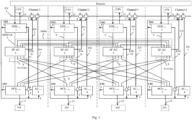
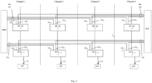
Figures 1 and2 show block diagram of the four-channel control safety system CSS structure, where: 1 are I/O stations IOS1 - n, n is a number of IOS stations in one CSS channel; 2 is safety system automation controller SF AC; 3 are priority control stations PCS1 - m, m is a number of PCS stations in one CSS channel; 4 are normal operation automation controllers AC1 - s, s is a number of controllers in one CSS channel; 5 is redundant bus EN of normal operation; 6 are net switches of EN and ENL buses; 7 are binary signals of CSS channels equipment state (operative/inoperative); 8 is interprocessor interface IPI of communication of each safety channel SF AC controllers with SF AC of other safety channels; 9 is a safety I/O bus SF IOB; 10 is redundant bus ENL of normal operation; 11 are control signals for actuation mechanisms AM; 12 are control signals for control and protection system CPS; 13 1 are wire lines of communication of PCS stations of each CSS channel with the MCR; 13 2 are wire lines of communication of PCS stations of each CSS channel with the ECR; 14 1 are IPI1 buses of communication of each safety channel SF AC controllers with the MCR; 14 2 are IPI2 buses of communication of each safety channel SF AC controllers with the ECR. -
Figure 3 shows block diagram of I/O station IOS (using the example of IOS1 station of channel 1), where: 9 is a segment of I/O bus SF IOB; 10 (10 1, 10 2) is redundant bus ENL (ENL1, ENL2); 15 1 - 15 k are modules of communication with the process MCP, k is a number of MCP modules in IOS station; 16 is communication module CIC; 17 are lines ofCIC module 16 communication with MCP modules 15 1 - 15 k via SF IOBbus 9; 18 1 is communication line ofCIC module 16 of IOS1 station with automation controller SF AC via SF IOBbus 9; 19 (19 1, 19 2) is redundant I/O bus of normal operation NO IOB (NO IOB1, NO IOB2); 20 (20 1, 20 2) are redundant interface modules IMN (IMN1, IMN2) of NO IOB bus interfacing with ENL bus. -
Figure 4 shows block diagram of MCP module of analog signal input, where 17 is a line of SFCPU processor 21 communication via SF IOB bus with CIC module; 19 (19 1, 19 2) are lines of normaloperation processor CPU 22 communication with redundant modules IMN1 and IMN2 via redundant bus NO IOB (NO IOB1, NO IOB2); 21 is a safety feature processor SF CPU; 21a is a safety feature analog-to digital converter ADC, 22 is a normal operation processor NO CPU; 22 a is a normal operation analog-to digital converter ADC; 22 b are input circuits of MCP module. -
Figure 5 shows the structure of a priority control station PCS using the example of PCS station being part of a group of 4 stations of a 4-channel CSS, with which automation controller SF AC of each channel implements data exchange via one communication line of SF IOB bus, where: 7 (71, 72) are generalized discrete fault signals ERR of safety and normal operation equipment of IOS station, 9 is a segment of I/O bus SF IOB; 10 (10 1, 10 2) is redundant bus ENL (ENL1, ENL2); 19 (19 1, 19 2) is redundant I/O bus of normal operation NO IOB (NO IOB1, NO IOB2); 20 (20 1, 20 2) are redundant interface modules IMN (IMN1, IMN2) of NO IOB bus interfacing with ENL bus; 23 1 - 23 e are priority control modules PCM, e is a number of PCM modules in PCS station; 24 is communication module of voting according to '2 out of 4' VM principle; 25 is communication module VCM; 26 is a line of communication ofVCM 25 with SF AC controller of its own or other safety channel via SF IOBbus 9; 27 are interstation lines of communication of VCM (VM) modules of PCS station of the group of PCS1 - 4 stations with VM (VCM) modules of the other 3 stations of the group via SF IOBbus 9; 28 are lines of communication ofVM module 24 via SF IOBbus 9 with PCM modules 23 1 - 23 e; 29 is a line of communication ofVCM module 25 withVM module 24 of its PCS station. -
Figure 6 shows the structure of links via SF IOB bus of agroup 1 of 4 stations PCS1 - 4 of safety channel 1-4 of a 4-channel CSS with SF AC controllers of 4 safety channels, where: 9 is a segment of SF IOB bus; 24 is communication module of voting VM; 25 is communication module VCM; 26 (26 11, 26 22, 26 33, 26 44) are lines of communication via bus SF IOB of VCM modules of PCS stations ofgroup 1 with controllers SF AC of, respectively, channels 1 - 4; 27 (27 12, 27 13, 27 14, 27 21, 27 23, 27 24, 27 31, 27 32, 27 34, 27 41, 27 42, 27 43) are inter-station (inter-channel) lines of communication of VCM module of each PCS1-4 station with VM modules of 3 other 3 stations via SF IOB bus; 28 are communication lines ofVM module 24 via SF IOBbus 9 with PCM modules 23 1 - 23 e; 29 is a intra-station (channel) line of communication ofmodule VCM 25 withVM module 24 of PCS station of its channel. -
Figure 7 provides block diagram of priority control module PCM, where: 13 1 are wire lines of AM remote control from the MCR; 13 2 are wire lines of AM remote control from the ECR; 19 1, 19 2 are communication lines of redundant bus NO IOB1, NO IOB2; 28 is communication line of SF IOB bus; 30 is programmable logic circuit SF PLC; 31 is normal operation processor CPU; 32 is programmable logic circuit of priority control logic PCL PLC; 33 is AM state inputs line; 34 is a feedback link for interrogation of a state of control command sent to AM. -
Figure 8 shows a block diagram of SF AC automation controller (using the example ofchannel 1 SF AC), where: 5 1, 52 is redundant bus EN of normal operation; 812, 8 13, 8 14 are interprocessor interfaces IPI ofchannel 1 SF AC communication with SF AC ofchannels channel 1 via buses IPI1, IPI2, respectively, with MCR and ECR; 18 1, 18 2, 18 3, 18 4 are communication links of communication module BM-4 361-3 of channels 1 - 4, respectively, with groups 1 - 4, 5 - 8, 9 - 12 of stations IOS1, IOS2, IOS3, IOS4 channels 1 - 4 via SF IOB bus (Figure 8 shows only IOS groups 1 - 4, connected to module BM-41 361); 26 11, 26 12, 26 13, 26 14 are communication lines of module BM-4 364 , respectively, with stations PCS 1-4 of group via SF IOB (to each module BM-4 5-11 according to the same scheme, respectively, modules of stations PCS 1-4 are connected with 7 more groups of stations: 5 - 8, 9 -12, 13 - 16, 17 - 20, 21 - 24, 25 - 28, 29 - 32); 35 is automation processor module SF APM; 36 1 - 36 p are communication modules BM-4; 37 1 - 37 p are are communication lines of module SF APM 35 with communication modules BM-4 via bus SF IOB. - CSS software & hardware complex, schematically represented in
Figures 1 and2 using the example of 4-channel control safety system CSS, operates in the following way. - I/O stations IOS1-n of each safety channel receive analog and binary signals of the process, convert them into digital form, and transmit via safety I/O bus SF IOB 9 to safety channel automation controller SF AC 2. Following commands of SF
AC controller 2, IOS stations generate and send control signals for CPS as shown inFigure 1 . - SF
AC controller 2 converts received digital values of analog and binary signals into process parameters, transmits them via interprocessor interface IPI 8 to automation controllers SF AC 2 of other safety channels, receives process parameters from these safety channels, and executes software-based selection of parameters for further processing according to majority algorithm '2 out of 4' at the first level of interchannel communications and majority redundancy. Automation controller SF AC 2 compares process parameters, selected according to the majority algorithm, with the predetermined limits of nuclear power plant safety operation. Further processing of the received process parameters is executed at several stages of implementation of protection algorithms, including intermediate conversion of the results of processing, interchannel communications viaIPI interfaces 8, and majority processing at every stage. - If SF AC controller 2 detects an emergency situation as a result of analysis of input process parameters, it generates and sends via SF IOB
bus 9 protection commands to the priority control stations PCS1 - m 3 of its own safety channel and toPCS stations 3 of other safety channels at the second level of interchannel communications. - If the emergency situation requires reactor trip, then SF AC 2 sends via SF IOB bus to respective IOS stations control commands for CPS.
- Automation controller SF AC 2 in the process of operation generates and sends to the upper level of the normal operation system via normal operation bus EN 5 diagnostic information about execution of protection functions and about the state of SF AC and IOS/PCS stations. Reception of information in SF AC 2 via EN bus from the normal operation system is blocked.
- Priority
control stations PCS 1 - m 3 receive actuation mechanism control commands fromSF AC controller 2 of their own channel and fromSF AC 2 of the other safety channels, and execute their hardware-based processing according to redundancy principle '2 out of 4' at the second level of interchannel communications and majority redundancy. - PCS1 - m stations 3, based on the commands selected according to majority principle, generate control signals for actuation mechanisms AM 11.
- PCS1 - m stations 3 of the safety channel receive also control commands from other control centers: main control room MCR, emergency control room ECR, and normal operation system, and generate control signals for
AM 11 according to priorities of the control centers. - According to
Figure 2 the MCR and ECR are connected directly to PCS1 - m stations 3 of each safety channel via wire lines, and toSF AC controllers 2 via communication lines of buses IPI1 14 1, IPI2 14 2 of Ethernet 'point-to-point'-type interface with specific data-level communications protocol. - Via wire communication lines 13 1 , 13 2 , from MCR and ECR to
PCS 1 - m 3 binary control signals are transmitted, and fromPCS 1 - m 3 to MCR and ECR signals reflecting the state of priority control stations andAM 11 are transmitted to be displayed on safety panels. - Via communication lines IPI1 14 1, IPI2 14 2, from SF AC controller of 2 safety channels to MCR and ECR diagnostic information about execution of protection algorithms and extended diagnostic information about the state of actuation mechanisms and priority control modules is transmitted.
- Access to CSS sensors and actuation mechanisms from the side of the normal operation system is implemented via redundant bus EN 5 through normal operation automation controllers AC1 - s 4 (
Figure 1 ) being part of the CSS, and through normal operation software & hardware of IOS and PCS stations. - Normal operation
automation controllers AC 1 - s 4 of the CSS configuration are connected withIOS 1 - n 1 and PCS1 - m stations 3, and respectively, with CSS sensors and actuation mechanisms viaredundant bus ENL 10, similarly to the connection of AC controllers, being part of the normal operation system, with their stations, and execute normal operation system functions of processing data coming from CSS sensors if there is no emergency situation, and function of collecting data needed for evaluation of NPP state. -
Controllers AC 1-s 4 exchange data with AC controllers being part of the normal operation system and with the upper level system in accordance with the purposes of the normal operation system, and transmit information about the performance of normal operation functions to the upper control level viaredundant bus EN 5.Controllers AC 1 - s 4 also implement additional functions of collecting, analysis and transmission to the upper level of the state of binary fault signals 7 (Figure 1 ) generated by hardware means of CSS equipment, including safety features and normal operation means built in IOS, PCS stations, as well as CSS power supply and communications equipment. These signals are generated by self-monitoring software and hardware of the corresponding CSS equipment using the contacts of signal relays, are received bycontrollers AC 1 - s 4 via discrete signal input channels and are transmitted to the upper control level even if the controlled CSS device itself cannot perform this functionally or due to a malfunction. -
SF AC controller 2 is connected withIOS 1 - n 1 andPCS 1 - m 3 stations via specific I/Obus SF IOB 9. -
SF IOB bus 9 is implemented using duplex serial interfaces of 'point-to-point' type and has 'tree'-type structure, in the upper root node of which an automation processor module SF APM is connected to the bus, and in the bottom nodes - MCP and PCM modules are connected. In the intermediate nodes of the structure communication modules of automation controller, I/O stations and priority control stations are placed. - The bus has two groups of 'point-to-point'-type communication lines: lines of downstream data and commands from SF APM processor module to MCP input/output modules and priority control modules PCM, and upstream data lines from MCP and PCM modules to SF APM processor module. For downstream data the communication module implements branching of data, coming via one of the 'tree' lines from the upper bus node, to several communication lines to the low bus nodes; and for the upstream data it implements concentration of data, coming to the module via several communication lines of the 'tree' from low bus nodes, to one communication line to the upper bus nodes. Communication modules VM in the priority control stations PCS execute also majority processing according to `2 out of N' principle of downstream commands and data from all safety channels at the second level of inter-channel communications.
- IOS station, which structure is shown in
Figure 3 using the example of IOS1 station ofchannel 1, contains:communication module CIC 16 ofSF IOB bus 9, modules of communication with the process MCP 15 1 - 15 k . CIC module is connected via separate communication lines ofSF IOB 17 of 'point-to-point' type of serial duplex interface with each MCP module 15 1 - 15 k, and via communication line of SF IOB bus 18 1 - with automation controller SF AC. -
Communication module CIC 16 distributes commands and data coming via SF IOB line 23 1 fromSF AC controller 2, to SF IOB lines 17 of communication with MCP modules, and concentrates data coming vialines 17 from MCP modules to SF IOB line 18 1 of IOS station communication with SF AC. Via communication line 18 1 an access to each MCP module of I/O station from the side of SF AC for data transmission and reception is implemented. - IOS station additionally contains independent software & hardware of normal operation that ensure access to sensors and actuation mechanisms from the side of the normal operation system: normal operation processors integrated into MCP modules that implement preprocessing of the process signals according to normal operation algorithms, and means of their communication with normal operation controllers AC of the CSS configuration.
- Communication of MCP modules and, respectively, of integrated into them normal operation processors with the normal operation system is implemented using redundant interface modules IMN1 20 1, IMN2 20 2 and redundant I/O bus of normal operation NO IOB1 19 1, NO IOB2 19 2. NO IOB bus consists of 'point-to-point'-type lines of serial duplex interface connecting each redundant module IMN1 20 1, IMN2 20 2 with each MCP module 15 1 - 15 k.
- Redundant modules IMN1 20 1, IMN2 20 2 implement functions of
redundant bus ENL 1 10 1,ENL 2 10 2 interfacing with intra-station redundant I/O bus NO IOB1 19 1, NO IOB2 19 2 through which commands for inputting the values of the input signals or for reproducing the output process signals are transmitted to the input / output modules and the state-of-health status of the input / output modules is polled. Based on the results of the polling, modules IMN1 201, IMN2 202 generate generalized discrete state-of-health signals of the IOS station through the contacts of signal relays. - Modules of communication with the process MCP 15 1 - 15 k execute reception and reproduction of analog and binary signals of the process, conversion of input signals of the process into digital form and digital values of output signals into analog form, preprocessing of input signals, communication with SF AC controllers via
communication lines 17, 18 1 ofSF IOB bus 9, and communications with normal operation controllers AC via redundant bus NO IOB1, NO IOB2, and further via redundant bus ENL (ENL1, ENL2) 10 1, 102. -
Figure 4 shows the structure of MCP module of analog signal input. - Process signal input and processing functions according to safety algorithms are implemented by safety feature
processor SF CPU 21. - Process signal input and processing functions according to normal operation algorithms are implemented by individual
normal operation processor 22 meeting diversity requirements relative to safety featureprocessor SF CPU 21. - Process signal comes in analog signal input module MCP via
input circuits 22a to the input of analog-to-digital converter ADC 22 b that converts the signal into digital form.Processor SF CPU 21 receives digital signal fromADC 22 b output, executes its preprocessing according to safety algorithm, and transmits it, respectively, viacommunication line 17 of SF IOB bus to communication module CIC of IOS station. -
Normal operation processor 22 implements processing of digital signal received fromADC 22 b output according to normal operation algorithm, and transmits the result of processing via redundant intra-station bus NO IOB1 19 1, NO IOB2 19 2 to redundant interface modules IMN1 20 1, IMN2 202 for further transmission viaredundant bus ENL 1 10 1, ENL 2 102 (Figure 3 ) to normal operation controller AC. - Binary signal input modules and analog and binary signal output modules operate according to similar scheme.
-
Figure 5 shows the structure of a priority control station PCS using the example of PCS station ofchannel 1 being part of a group of 4 stations PCS1 - 4, with which automation controller SF AC of each channel implements data exchange via one communication line of SF IOB bus. IOS station contains:communication module VCM 25, votingcommunication module VM 24, priority control modules PCM 23 1 - 23 e. VM module is connected: viaindividual communication lines 28 ofSF IOB 9 of 'point-to-point' type of serial duplex interface with each PCM module 23 1 - 23 e; via 3communication lines 27 ofSF IOB bus 9 withcommunication modules VCM 25 of the other 3 stations PCS. - Voting
communication module VM 24 implements functions of branching downstream commands and data from SF AC to PCM modules 231 - 23 e and concentrating upstream data from PCM modules 23 1 - 23 e to SF AC, and functions of hardware-based majority selection of downstream commands and data from 4 safety channels received viacommunication lines SF IOB 9 according to majority processing algorithm '2 out of 4' for transmission to PCM modules 23 1 - 23 e. -
Communication module VCM 25 is linked: vialine 29 of SF IOB withVM communication module 24 of its PCS station; via 3communication lines 27 of SF IOB - with VM communication modules of the other 3 stations ofsafety channel 1; viacommunication line 26 ofSF IOB bus 9 in PCS1 station - with SF AC of itsown safety channel 1 and in the other 3 PCS stations - with SF AC of the other 3 safety channels. -
Figure 6 shows structure of links via SF IOB bus of a group of 4 stations PCS1 - 4 of safety channel 1 (4-channel safety system) with SF AC controller of this safety channel and with SF AC controllers of the other 3 safety channels. - Communications of PCM modules 231 - 23 e with the normal operation system (
Figure 5 ) is implemented using redundant interface modules IMN1 20 1, IMN2 20 2, redundant bus NO IOB1 19 1, NO IOB2 , via which modules IMN1, IMN2 send commands to the PCM modules for generating the AM actuator control signals and reading the AM status received from the AC controller, and poll the "good / bad" status of the PCM modules. Based on the results of the polling, modules IMN1 20 1 , IMN2 202 generate generalized discrete state-of-health signals of the IOS station through the contacts of signal relays. -
Figure 7 shows arrangement of safety feature hardware, normal operation hardware and communication with AM control centers in PCM modules using block diagram of PCM module. - PCM module executes AM control following initiating commands from several control centers: from SF AC controller via
communication lines 28 of SF IOB bus; from normal operation controller AC viaredundant buses ENL 1 10 1,ENL 2 10 2 and NO IOB1 19 1, NO IOB2 19 2 (Figures 5 and7 ); from MCR via wire lines 13 1 and from ECR via wire lines 13 2. Via said links, transmission of PCM and AM state is executed, respectively, to SF AC, AC, MCR and ECR. - Generation of AM control commands is implemented: when initiated by commands from SF AC, MCR and ECR - in safety feature programmable logic
circuits SF PLC 30, and when initiated by commands from AC, MCR and ECR - in normaloperation processor CPU 31. - AM control commands from
SF PLC 30,CPU processor 31 come to PLC of priority controllogic PCL PLC 32, where a command to be sent to AM is generated. - Normal
operation processor CPU 31 executes based on commands from normal operation automation controller AC and together with it the functions of automatic control of actuation mechanisms in the normal operation system if there is no emergency situation, and functions of controlling the commands sent to AM from SF AC, receiving data of state of AM controlled from SF AC, and transmitting this data to AC normal operation controller via NO IOB and ENL buses for evaluation by it of NPP and safety channel state. - Via feedback link 34 from PCL PLC output,
line 28 of SF IOB bus, and redundant bus NO IOB1 19 1, NO IOB2 19 2 the controllers, respectively, SF AC and AC interrogate the state of commands sent to AM. And here AC controller inquires for the state of its commands sent to AM, and of commands sent to AM by SF AC controller. - Via
input line 33 the AM state signals come to MCR, ECR, and viaPCL PLC 32,SF PLC 30 and CPU processor 31 - to automation controllers, respectively, SF AC and AC. Here AC controller receives the AM state signals both when sending to AM its own commands, and when the commands are sent to AM by SF AC controller. -
Figure 8 shows structure of SF AC automation controller using the example ofchannel 1 of 4-channel safety system and scheme of communications of this controller and SF AC controllers of other safety channels with the IOS and PCS stations. In order to optimize the communications of SF AC with the IOS and PCS stations, they are combined into groups of 4 stations of the same name per group in accordance with the placement of these stations made in the form of standard crates, in instrument cabinets, 4 stations per cabinet. Automation controllers SF AC of 4 safety channels are located in 4 separate cabinets. - Automation controller SF AC is comprised of automation processor
module SF APM - Automation processor
module SF APM 35 of controller SF AC receives viabus SF IOB 9 digital values of process parameters from MCP modules of IOB1-n stations of its safety channel, processes them and, when an emergency is detected, in accordance with safety algorithms, generates and outputs viabus SF IOB 9 into PCM modules of PCS 1 - m stations of its own and other safety channels commands for controlling the protective actions to be selected for execution by the VM voting communication modules according to the voting principle '2 out of 4',Figure 6 ,8 . In the process of executing safety algorithms, theSF APM 35 module exchanges data with the SF APM modules of the 2nd, 3rd and 4th safety channels, respectively, via theIPI redundant bus EN - As shown in
Figure 8 , the SF AC controller setup for communications with IOS, PCS stations in a four-channel control safety system, the processor module APM executes reception of data from IOS stations and transmission of commands and data to PCS stations: via lines of bus SF IOB 371 - 3711 communication, respectively, with communication modules BM-4 361 - 3611, and further via 4 communication lines 181 - 184 3 of 3 modules BM-4 1-3 with IOB stations 1-4 of 3 groups or with 12 IOB stations and via 4 sets of communication lines 2611 - 2614, 2621 - 2624, 2631 - 2634, 2641 - 2644 of 8 modules BM-4 4-11 of all safety channels with 32 groups of CSS 1-4 stations or with 128 PCS stations. - Layout of CSS stations by 4 stations per cabinet in accordance with the number of safety channels ensures optimization of a large number of channel and inter-channel communications via the input / output bus SF IOB between the SF AC controllers and the PCS stations in connection with the fundamental decision to architect the bus based on 'point-to-point' interfaces with full-duplex command and data transmission mode and locate VM voting communication modules in the lower end nodes of the bus.
- Optimization consists in reducing the cable connections between the SF AC cabinets of four channels and each of the 32 PCS cabinets to 4 minimum required, and in implementing inter-channel communications for voting in each of a cabinet's 4 PCS stations according to the '2 out of 4' principle by means of communication modules VCM , VM and additional 'point-to-point' type cable connections inside the cabinets according to the scheme,
Fig. 6 , which are shorter and better protected than the cable connections between the cabinets.
Claims (4)
- Control safety system for use in nuclear plants, comprising:
a plurality of identical safety channels, each said channel includes process signal input/output stations IOS1-n (1), actuation mechanism priority control stations PCS1-m (3) that are connected with the main control room MCR and emergency control room ECR, safety features automation controller SF AC (2), safety features input/output bus SF IOB (9) for SF AC controller data exchange with the IOS1-n stations (1) and PCS1-m (3) stations, and is cross-connected with other safety channels by means of duplex optical fiber communication paths, characterized in that the said IOS1-n stations (1) contains modules of communication with the process and communication module MCP1-k (15) - converter of communication interfaces CIC (16) of SF IOB bus (9); said PCS1-m station (3) contains actuation mechanism priority control modules PCM1-e (23) and communication modules: voting communication module VCM (25) and voting module VM (24) of SF IOB bus (9); said SF AC (2) contains safety feature automation processor module SF APM (35) and communication modules - branching modules BM-41-p (36) of SF IOB bus (9); automation controllers SF AC (2) of all safety channels are connected to the normal operation system via redundant bus EN (5) built based on switched Ethernet interface, ring structure of net switches connection and data-level communication protocol; each safety channel contains additionally normal operation automation controllers AC1 - s (4) that are connected with IOS1 - n stations (1), PCS1 - m stations (3) via redundant buses ENL of normal operation (10) built based on switched Ethernet interface, radial structure of net switch connection and data-level communication protocol, and with the normal operation system via redundant bus EN (5) of normal operation; normal operation automation controllers AC (4), integrated into IOS1-n stations (1) and PCS1-m stations (3) means of AC communication with MCP1 - k module (15) and PCM (23) modules, and integrated into MCP1 - k module (15) and PCM (23) modules normal operation software & hardware are built based on different hardware & software platforms; IOS1-n stations (1) and PCS1-m stations (3), automation controller SF AC (2), and power supply and communication equipment of the safety system include built-in self-testing and self-monitoring features that generate at the outputs the binary signals of the respective equipment state 'operative/inoperative' coming to NO AC, where the signals are processed and transmitted to the upper level of the normal operation system control via EN bus (5)wherein the communication module CIC (16) of SF IOB bus (9) in IOS1-n stations (1) is connected via separate SF IOB communication lines with automation controller SF AC (2) of the safety channel and with each MCP1 - k module (15) of this station. - Control safety system for use in nuclear power plants according to claim 1, characterized in that each IOS1-n station (1) includes two redundant interface modules IMN (20) of normal operation connected to normal operation automation controller NO AC (4) via redundant bus ENL (10); each MCP1 - k module (15) includes integrated individual normal operation processor connected with each of the 2 modules IMN (20) via separate line of a serial duplex 'point-to-point'-type interface of normal operation bus NO IOB (19).
- Control safety system for use in nuclear power plant according to claim 1, characterized in that the PCS1-m stations (3) in each safety channel are combined into groups of N stations, a number of PCS stations (3) is determined by a number of safety channels, the first PCS1 station (3) of the group is connected via SF IOB communication line with automation controller SF AC (2) of its safety channel, the other PCS2 - N stations (3) of the group are connected with automation controllers SF AC (2) of the other 2-N safety channels; communication module VCM (25) of each PCS1-m station (3) is connected with communication module of voting according to `2 out of N' majority algorithm VM (24) of its own PCS1-m station (3) and with communication modules VM (24) of the other PCS1-m stations (3) of the group; communication module VM (24) of each PCS1-m station (3) is connected via SF IOB communication lines with priority control modules PCM1-e (23).
- Control safety system for use in nuclear power plant according to claim 3, characterized in that each PCS1-m station (3) contains two redundant interface modules IMN (20) of normal operation connected to normal operation automation controller NO AC (4) via redundant bus ENL (10); each PCM1 - e module (23) includes integrated individual normal operation processor connected with each of the 2 modules IMN (20) via separate line of a serial duplex 'point-to-point'-type interface of normal operation bus NO IOB (19).
Applications Claiming Priority (2)
| Application Number | Priority Date | Filing Date | Title |
|---|---|---|---|
| RU2015125046/08A RU2598599C1 (en) | 2015-06-25 | 2015-06-25 | Control system for safety of nuclear power plant |
| PCT/RU2016/000356 WO2016209114A1 (en) | 2015-06-25 | 2016-06-10 | Control system for the safety of nuclear power plant |
Publications (3)
| Publication Number | Publication Date |
|---|---|
| EP3316261A1 EP3316261A1 (en) | 2018-05-02 |
| EP3316261A4 EP3316261A4 (en) | 2019-04-17 |
| EP3316261B1 true EP3316261B1 (en) | 2023-12-27 |
Family
ID=57018427
Family Applications (1)
| Application Number | Title | Priority Date | Filing Date |
|---|---|---|---|
| EP16814795.7A Active EP3316261B1 (en) | 2015-06-25 | 2016-06-10 | Control system for the safety of nuclear power plant |
Country Status (5)
| Country | Link |
|---|---|
| EP (1) | EP3316261B1 (en) |
| KR (1) | KR102333907B1 (en) |
| CN (1) | CN107924722B (en) |
| RU (1) | RU2598599C1 (en) |
| WO (1) | WO2016209114A1 (en) |
Families Citing this family (3)
| Publication number | Priority date | Publication date | Assignee | Title |
|---|---|---|---|---|
| EP3576103A4 (en) * | 2017-01-24 | 2020-08-19 | China Techenergy Co., Ltd | Nuclear power plant priority management system |
| CN110398901B (en) * | 2019-04-28 | 2023-04-18 | 北京广利核系统工程有限公司 | Power-loss simulation method and device for DCS (distributed control System) simulator of nuclear power station |
| CN111555941B (en) * | 2020-04-30 | 2021-12-17 | 中国科学院长春光学精密机械与物理研究所 | Automatic generation method of communication protocol test driving data |
Family Cites Families (16)
| Publication number | Priority date | Publication date | Assignee | Title |
|---|---|---|---|---|
| US5745539A (en) * | 1995-11-14 | 1998-04-28 | Westinghouse Electric Corporation | Apparatus and method for prioritization of multiple commands in an instrumentation and control system |
| US6049578A (en) * | 1997-06-06 | 2000-04-11 | Abb Combustion Engineering Nuclear Power, Inc. | Digital plant protection system |
| US5984504A (en) * | 1997-06-11 | 1999-11-16 | Westinghouse Electric Company Llc | Safety or protection system employing reflective memory and/or diverse processors and communications |
| KR100265321B1 (en) | 1997-11-28 | 2000-09-15 | 윤덕용 | Dynamic safety system in a programmable logic controller for pressurized water reactor |
| RU2150756C1 (en) * | 1999-01-28 | 2000-06-10 | Грибов Алексей Алексеевич | Method for gathering and processing signals in nuclear reactor core monitoring system, and device for its embodiment |
| CN1119819C (en) * | 2000-11-10 | 2003-08-27 | 清华大学 | Digital reactor protecting system based on parallel hardware and software treatment |
| KR100848881B1 (en) * | 2006-08-07 | 2008-07-29 | 삼창기업 주식회사 | Digital Security System for Nuclear Power Plant |
| UA78477C2 (en) * | 2006-08-28 | 2007-03-15 | Yevhenii Stepanovych Bakhmach | Control digital safety system of nuclear station and method for providing the safety system parameters |
| KR100857145B1 (en) * | 2007-02-08 | 2008-09-05 | 한국원자력연구원 | Integrated Digital Engineered Safety Feature - Component Control System AND METHOD THEREOF |
| US8117512B2 (en) * | 2008-02-06 | 2012-02-14 | Westinghouse Electric Company Llc | Failure detection and mitigation in logic circuits |
| US20110313580A1 (en) * | 2010-06-17 | 2011-12-22 | Levgenii Bakhmach | Method and platform to implement safety critical systems |
| RU2431174C1 (en) * | 2010-08-20 | 2011-10-10 | Федеральное государственное унитарное предприятие "Всероссийский научно-исследовательский институт автоматики им. Н.Л. Духова" (ФГУП "ВНИИА") | Backup software-hardware system for automatic monitoring and control |
| KR101244015B1 (en) | 2011-09-09 | 2013-03-15 | 한국수력원자력 주식회사 | Nuclear power plant safety systems having indefendent multiplex structure and composition method |
| CN102426863B (en) * | 2011-10-31 | 2015-12-16 | 中广核工程有限公司 | Nuclear power plant reactor shutdown signal transmission system and method |
| RU2487372C1 (en) * | 2012-01-10 | 2013-07-10 | Федеральное государственное унитарное предприятие "Научно-исследовательский технологический институт имени А.П. Александрова" | Remote radiation monitoring system |
| CN104409123B (en) * | 2014-11-15 | 2017-06-16 | 北京广利核系统工程有限公司 | A kind of nuclear power station priority management system |
-
2015
- 2015-06-25 RU RU2015125046/08A patent/RU2598599C1/en active
-
2016
- 2016-06-10 WO PCT/RU2016/000356 patent/WO2016209114A1/en active Application Filing
- 2016-06-10 CN CN201680037434.6A patent/CN107924722B/en active Active
- 2016-06-10 KR KR1020177037691A patent/KR102333907B1/en active IP Right Grant
- 2016-06-10 EP EP16814795.7A patent/EP3316261B1/en active Active
Also Published As
| Publication number | Publication date |
|---|---|
| CN107924722A (en) | 2018-04-17 |
| KR102333907B1 (en) | 2021-12-03 |
| EP3316261A4 (en) | 2019-04-17 |
| WO2016209114A1 (en) | 2016-12-29 |
| KR20180036920A (en) | 2018-04-10 |
| EP3316261A1 (en) | 2018-05-02 |
| RU2598599C1 (en) | 2016-09-27 |
| CN107924722B (en) | 2021-11-23 |
| WO2016209114A9 (en) | 2017-02-02 |
Similar Documents
| Publication | Publication Date | Title |
|---|---|---|
| EP3316262B1 (en) | Safety control system for a nuclear power plant | |
| EP1010044B1 (en) | Safety or protection system employing reflective memory and/or diverse processors and communications | |
| CN102096401B (en) | Redundant and fault-tolerant safety instrument control system based on fieldbus and ARM (advanced RISC machines) | |
| US20180211734A1 (en) | Reactor protection-processor-to-reactor-trip breaker interface and method for operating the same | |
| CN105575448A (en) | Nuclear power station reactor protection system and safety control method therein | |
| EP3316261B1 (en) | Control system for the safety of nuclear power plant | |
| KR100848881B1 (en) | Digital Security System for Nuclear Power Plant | |
| CN108287519B (en) | Logical construction and implementation method for proton therapy equipment safety interlocking | |
| EP3316260A1 (en) | Safety control system for nuclear power plant | |
| US6473479B1 (en) | Dual optical communication network for class 1E reactor protection systems | |
| CN111681792B (en) | ATWT control device and nuclear power equipment | |
| KR20230064270A (en) | Apparatus, method and system for high-speed control platform for voltage direct current transmission network | |
| KR101298459B1 (en) | Bus structure of fpga based controler | |
| Lee et al. | Risk assessment of safety-critical data communication in digital safety feature control system | |
| Suh et al. | Developing architecture for upgrading I&C systems of an operating nuclear power plant using a quality attribute-driven design method | |
| CN105867316B (en) | The integritied monitoring and controling system of power station steam turbine electrohydraulic control system based on Modbus agreements | |
| CN211529626U (en) | DCS (distributed control system) architecture for nuclear power reactor | |
| CA2304438C (en) | Safety or protection system employing reflective memory and/or diverse processors and communications | |
| Kim et al. | Implementation of Multiloop Control for the Plant Control System in Improved Korean Standard Nuclear Power Plant (KSNP+) | |
| Gomez et al. | Application of DCS to new build CANDU designs using the G-HIACS vSAFE platform |
Legal Events
| Date | Code | Title | Description |
|---|---|---|---|
| STAA | Information on the status of an ep patent application or granted ep patent |
Free format text: STATUS: THE INTERNATIONAL PUBLICATION HAS BEEN MADE |
|
| PUAI | Public reference made under article 153(3) epc to a published international application that has entered the european phase |
Free format text: ORIGINAL CODE: 0009012 |
|
| STAA | Information on the status of an ep patent application or granted ep patent |
Free format text: STATUS: REQUEST FOR EXAMINATION WAS MADE |
|
| 17P | Request for examination filed |
Effective date: 20171227 |
|
| AK | Designated contracting states |
Kind code of ref document: A1 Designated state(s): AL AT BE BG CH CY CZ DE DK EE ES FI FR GB GR HR HU IE IS IT LI LT LU LV MC MK MT NL NO PL PT RO RS SE SI SK SM TR |
|
| AX | Request for extension of the european patent |
Extension state: BA ME |
|
| DAV | Request for validation of the european patent (deleted) | ||
| DAX | Request for extension of the european patent (deleted) | ||
| A4 | Supplementary search report drawn up and despatched |
Effective date: 20190315 |
|
| RIC1 | Information provided on ipc code assigned before grant |
Ipc: G05B 9/03 20060101ALI20190311BHEP Ipc: G21C 7/36 20060101AFI20190311BHEP Ipc: G21D 3/04 20060101ALI20190311BHEP |
|
| STAA | Information on the status of an ep patent application or granted ep patent |
Free format text: STATUS: EXAMINATION IS IN PROGRESS |
|
| 17Q | First examination report despatched |
Effective date: 20200717 |
|
| STAA | Information on the status of an ep patent application or granted ep patent |
Free format text: STATUS: EXAMINATION IS IN PROGRESS |
|
| STAA | Information on the status of an ep patent application or granted ep patent |
Free format text: STATUS: EXAMINATION IS IN PROGRESS |
|
| REG | Reference to a national code |
Ref country code: DE Ref legal event code: R079 Ref document number: 602016085022 Country of ref document: DE Free format text: PREVIOUS MAIN CLASS: G21C0007360000 Ipc: G05B0009030000 Ref country code: DE Ref legal event code: R079 Free format text: PREVIOUS MAIN CLASS: G21C0007360000 Ipc: G05B0009030000 |
|
| GRAP | Despatch of communication of intention to grant a patent |
Free format text: ORIGINAL CODE: EPIDOSNIGR1 |
|
| STAA | Information on the status of an ep patent application or granted ep patent |
Free format text: STATUS: GRANT OF PATENT IS INTENDED |
|
| RIC1 | Information provided on ipc code assigned before grant |
Ipc: G21D 3/04 20060101ALI20230707BHEP Ipc: G21C 7/36 20060101ALI20230707BHEP Ipc: G05B 9/03 20060101AFI20230707BHEP |
|
| INTG | Intention to grant announced |
Effective date: 20230728 |
|
| GRAS | Grant fee paid |
Free format text: ORIGINAL CODE: EPIDOSNIGR3 |
|
| GRAA | (expected) grant |
Free format text: ORIGINAL CODE: 0009210 |
|
| STAA | Information on the status of an ep patent application or granted ep patent |
Free format text: STATUS: THE PATENT HAS BEEN GRANTED |
|
| AK | Designated contracting states |
Kind code of ref document: B1 Designated state(s): AL AT BE BG CH CY CZ DE DK EE ES FI FR GB GR HR HU IE IS IT LI LT LU LV MC MK MT NL NO PL PT RO RS SE SI SK SM TR |
|
| REG | Reference to a national code |
Ref country code: GB Ref legal event code: FG4D |
|
| REG | Reference to a national code |
Ref country code: CH Ref legal event code: EP |
|
| REG | Reference to a national code |
Ref country code: DE Ref legal event code: R096 Ref document number: 602016085022 Country of ref document: DE |
|
| REG | Reference to a national code |
Ref country code: IE Ref legal event code: FG4D |
|
| PG25 | Lapsed in a contracting state [announced via postgrant information from national office to epo] |
Ref country code: GR Free format text: LAPSE BECAUSE OF FAILURE TO SUBMIT A TRANSLATION OF THE DESCRIPTION OR TO PAY THE FEE WITHIN THE PRESCRIBED TIME-LIMIT Effective date: 20240328 |
|
| REG | Reference to a national code |
Ref country code: LT Ref legal event code: MG9D |
|
| PG25 | Lapsed in a contracting state [announced via postgrant information from national office to epo] |
Ref country code: LT Free format text: LAPSE BECAUSE OF FAILURE TO SUBMIT A TRANSLATION OF THE DESCRIPTION OR TO PAY THE FEE WITHIN THE PRESCRIBED TIME-LIMIT Effective date: 20231227 |