EP3316261B1 - Steuerungssystem zur sicherheit eines kernkraftwerks - Google Patents
Steuerungssystem zur sicherheit eines kernkraftwerks Download PDFInfo
- Publication number
- EP3316261B1 EP3316261B1 EP16814795.7A EP16814795A EP3316261B1 EP 3316261 B1 EP3316261 B1 EP 3316261B1 EP 16814795 A EP16814795 A EP 16814795A EP 3316261 B1 EP3316261 B1 EP 3316261B1
- Authority
- EP
- European Patent Office
- Prior art keywords
- stations
- normal operation
- safety
- communication
- pcs
- Prior art date
- Legal status (The legal status is an assumption and is not a legal conclusion. Google has not performed a legal analysis and makes no representation as to the accuracy of the status listed.)
- Active
Links
- 238000004891 communication Methods 0.000 claims description 139
- 238000000034 method Methods 0.000 claims description 38
- 230000008569 process Effects 0.000 claims description 30
- 230000007246 mechanism Effects 0.000 claims description 23
- 238000012544 monitoring process Methods 0.000 claims description 13
- 239000013307 optical fiber Substances 0.000 claims description 6
- 238000012360 testing method Methods 0.000 claims description 5
- 238000012545 processing Methods 0.000 description 19
- 230000005540 biological transmission Effects 0.000 description 11
- 238000010586 diagram Methods 0.000 description 6
- 238000006243 chemical reaction Methods 0.000 description 3
- 238000011156 evaluation Methods 0.000 description 3
- 230000000977 initiatory effect Effects 0.000 description 3
- 238000007781 pre-processing Methods 0.000 description 3
- 238000011084 recovery Methods 0.000 description 3
- 238000011144 upstream manufacturing Methods 0.000 description 3
- 238000001514 detection method Methods 0.000 description 2
- 230000004807 localization Effects 0.000 description 2
- 238000005457 optimization Methods 0.000 description 2
- 230000001681 protective effect Effects 0.000 description 2
- 230000009471 action Effects 0.000 description 1
- 239000012141 concentrate Substances 0.000 description 1
- 230000001419 dependent effect Effects 0.000 description 1
- 238000011161 development Methods 0.000 description 1
- 230000007717 exclusion Effects 0.000 description 1
- 238000012905 input function Methods 0.000 description 1
- 230000007257 malfunction Effects 0.000 description 1
- 230000003287 optical effect Effects 0.000 description 1
- 230000009467 reduction Effects 0.000 description 1
- 230000000246 remedial effect Effects 0.000 description 1
- 102200052313 rs9282831 Human genes 0.000 description 1
Images


Classifications
-
- G—PHYSICS
- G21—NUCLEAR PHYSICS; NUCLEAR ENGINEERING
- G21C—NUCLEAR REACTORS
- G21C7/00—Control of nuclear reaction
- G21C7/36—Control circuits
-
- G—PHYSICS
- G05—CONTROLLING; REGULATING
- G05B—CONTROL OR REGULATING SYSTEMS IN GENERAL; FUNCTIONAL ELEMENTS OF SUCH SYSTEMS; MONITORING OR TESTING ARRANGEMENTS FOR SUCH SYSTEMS OR ELEMENTS
- G05B9/00—Safety arrangements
- G05B9/02—Safety arrangements electric
- G05B9/03—Safety arrangements electric with multiple-channel loop, i.e. redundant control systems
-
- G—PHYSICS
- G21—NUCLEAR PHYSICS; NUCLEAR ENGINEERING
- G21D—NUCLEAR POWER PLANT
- G21D3/00—Control of nuclear power plant
- G21D3/001—Computer implemented control
-
- G—PHYSICS
- G21—NUCLEAR PHYSICS; NUCLEAR ENGINEERING
- G21D—NUCLEAR POWER PLANT
- G21D3/00—Control of nuclear power plant
- G21D3/04—Safety arrangements
-
- Y—GENERAL TAGGING OF NEW TECHNOLOGICAL DEVELOPMENTS; GENERAL TAGGING OF CROSS-SECTIONAL TECHNOLOGIES SPANNING OVER SEVERAL SECTIONS OF THE IPC; TECHNICAL SUBJECTS COVERED BY FORMER USPC CROSS-REFERENCE ART COLLECTIONS [XRACs] AND DIGESTS
- Y02—TECHNOLOGIES OR APPLICATIONS FOR MITIGATION OR ADAPTATION AGAINST CLIMATE CHANGE
- Y02E—REDUCTION OF GREENHOUSE GAS [GHG] EMISSIONS, RELATED TO ENERGY GENERATION, TRANSMISSION OR DISTRIBUTION
- Y02E30/00—Energy generation of nuclear origin
- Y02E30/30—Nuclear fission reactors
Definitions
- the invention relates to automatics and computer engineering, and can be used in I&C systems of nuclear power plants (NPP) for constructing control safety systems (CSS) of NPP.
- NPP nuclear power plants
- CSS control safety systems
- a digital plant protection system is known ( U.S. Patent No. 6049578, IPC G21C 7/36, published on April 11, 2000 , analog), which consists of four identical processing & control channels that provide detection of a trip condition at a facility by means of comparison of measured parameter values with predetermined setpoints and execution of user-specified remedial actions in case the parameters are out-of-specification.
- Safety channels physically separated from one another, are cross-connected with each other by optical fiber communication paths. Each channel includes analog and digital sensors associated with this channel; analog-to-digital converters that provide at the output digital representation of the measured analog signals; a bistable processor; a coincidence logic processor, and a logic processor initiating actuation mechanisms (AM) and automatic safety features of a reactor.
- AM actuation mechanisms
- the bistable processor accepts digital values of measured signals of its own channel, convert them into the process-dependent parameters, checks measured parameters for deviation beyond the predetermined limits, generates for each parameter a binary sign of deviation, transmits these signs via optical fiber lines to other processing & control channels.
- the coincidence logic processor receives from the bistable processor of its channel the binary signs of parameters deviation for the signals of this channel, and receives via optical fiber lines from the other channels the binary signs of deviation for the respective parameters. For every parameter the coincidence logic processor checks receipt of signs of beyond-limit deviation of 2 out of 4 channels. If the coincidence processor detects deviation from the permissible values of the parameters for 2 out of 4 channels, then initiation logic processor generates needed signals for reactor trip and for actuation of digital safety features.
- the protection system has the following disadvantages.
- US 2011/313580 A1 discloses a method of monitoring and controlling plant operations, which receive input signals from sensors monitoring parameters of plant operation to generate output signals to actuators. This method comprises: reducing the input signals to a selected group of input functions; reducing the output signals to a selected group of output functions; processing the input signals using FPGA to generate the output signals.
- the invention also relates to the platform and system embodying the method.
- US 2011/209021 A1 discloses methods of monitoring logic circuits for failures. These methods are directed toward establishing parallel logic cores where failures are detected by comparing the parallel paths for equivalence at key locations by a redundancy checker. Any mismatch will result in a predetermined failsafe operational mode. In addition, important techniques are applied to periodically exercise individual parallel paths to ensure that logic cores are verified in a way that does not disturb any process being monitored or controlled. The invention also relates to a high integrity logic circuits embodying the methods.
- a digital control safety system (DCSS) of nuclear power plant together with a method of safety parameters provision is known ( RU patent No. 2356111, IPC G21C7/36, published in 2009 , prototype), which consists of three separate identical safety channels executing evaluation of a facility state by means of the analysis of the parameter values received from the process sensors, and generating control protective actions in case of emergency situation.
- Physically separated safety channels are cross-connected with each other by optical fiber communication paths.
- Each channel includes an input device, comparator, control action generating device, lockout selection device, and actuation mechanisms control device.
- the input device executes input of analog signals of the process and their conversion into digital form.
- the comparator compares read out parameter values with pre-determined digital values and starts the device generating control signals, based on which the lockout selection device initiates generation of actuation mechanism control signals.
- Each digital processing device of the safety channel is cross-connected via interchannel optical lines with each respective device in other channels, forming 4 levels of interchannel communication paths and majority redundancy according to ⁇ 2 out of 3' principle.
- Majority processing of control commands from the 3 safety channels is also implemented by hardware at the inputs of devices controlling actuation mechanisms AM.
- the prototype DCSS contains wire lines of communication of safety channel AM control devices with the main control room (MCR) and emergency control room (ECR), via which remote control of actuation mechanisms from MCR and ECR as well as transmission of data on the state of these mechanisms to MCR and ECR is implemented.
- MCR main control room
- ECR emergency control room
- the prototype has the following disadvantages.
- Technical result of the invention includes reduction of inputs for monitoring and automatic control of general NPP equipment from the side of the safety and normal operation systems owing to normal operation features integrated in safety channels, enhancement of safety system reliability and protection against common cause failures by means of constructing safety features and normal operation features based on different software & hardware platforms, extension of CSS diagnostic capabilities owing to implementation by a normal operation automation controller of additional functions of evaluating safety channel operation using NPP state-of-health data received by the controller from the process and from the automation controllers of safety channels, extension of CSS diagnostic capabilities owing to equipment state-of-health control features integrated into CSS generating special fault signals, and their input, processing and transmission by the normal operation automation controller to the upper level of the normal operation system control.
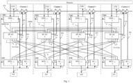
- each channel includes process signal I/O stations IOS 1 - n , actuation mechanism priority control stations PCS 1-m connected with the main control room MCR and emergency control room ECR, safety features automation controller (SF AC), safety feature I/O bus SF IOB for data exchange between SF AC and IOS/PCS stations, and is cross-connected with other safety channels by means of duplex optical fiber communication paths;
- the IOS station contains modules of communication with the process MCP 1 - k and communication module - converter of communication interfaces CIC of SF IOB bus;
- the PCS station contains actuation mechanism priority control modules PCM 1 - e and communication modules: voting communication module VCM and voting module VM of SF IOB bus;
- the automation controller SF AC contains safety feature automation processor module SF APM and communication modules - branching modules BM-4 1 - p of SF IOB bus; automation controllers SF AC of all safety channels are connected to the normal operation system
- IOS station communication module CIC of SF IOB bus via separate SF IOB communication lines is connected with automation controller SF AC of safety channel and with each MCP 1 - k module of this station.
- Each IOS station contains two redundant interface modules IMN of normal operation connected to normal operation automation controller NO AC via redundant bus ENL; an individual normal operation processor is built in each MCP 1 - k module, which is connected with each of the 2 IMN modules via separate line of a serial duplex 'point-to-point'-type interface of the normal operation bus NO IOB.
- each safety channel PCS stations are combined into groups of N stations, a number of PCS stations is determined by a number of safety channels; the first station of the group PCS 1 via SF IOB communication line is connected with SF AC controller of its safety channel, other stations PCS 2-N of the group are connected with SF AC controllers of the other safety channels 2-N; communication module VCM of each station PCS is connected with communication module of voting according to '2 out of N' majority algorithm VM of its PCS station and communication modules VM of other PCS stations of the group; communication module VM of each PCS station is connected via SF IOB communication lines with priority control modules PCM 1 - e of this station.
- Each PCS station contains two redundant interface modules IMN of normal operation connected to normal operation automation controller NO AC via redundant bus ENL; an individual normal operation processor is built in each PCM 1 - e module, which is connected with each of the 2 IMN modules via separate line of serial duplex 'point-to-point'-type interface of the normal operation bus NO IOB.
- Connection of SF AC and AC controllers to the normal operation bus EN ensures transmission to the upper control level of the normal operation system of diagnostic information about execution of safety and normal operation functions of the CSS and about the state-of-health of the equipment within the CSS, which extends diagnostic capabilities for timely detection of fault conditions and restoration of the CSS.
- Normal operation software & hardware additionally included into the CSS configuration are built based on processors, programmable logic circuits PLC, basic and system software, and development tools meeting diversity requirements for software & hardware safety features. This ensures exclusion of simultaneous common cause failure of safety and normal operation software & hardware features of the CSS. In case of common cause failure of safety channels, including an accident, the normal operation system detects this event and stops NPP.
- I/O stations IOS 1-n of each safety channel receive analog and binary signals of the process, convert them into digital form, and transmit via safety I/O bus SF IOB 9 to safety channel automation controller SF AC 2 .
- IOS stations Following commands of SF AC controller 2 , IOS stations generate and send control signals for CPS as shown in Figure 1 .
- SF AC controller 2 converts received digital values of analog and binary signals into process parameters, transmits them via interprocessor interface IPI 8 to automation controllers SF AC 2 of other safety channels, receives process parameters from these safety channels, and executes software-based selection of parameters for further processing according to majority algorithm '2 out of 4' at the first level of interchannel communications and majority redundancy.
- Automation controller SF AC 2 compares process parameters, selected according to the majority algorithm, with the predetermined limits of nuclear power plant safety operation. Further processing of the received process parameters is executed at several stages of implementation of protection algorithms, including intermediate conversion of the results of processing, interchannel communications via IPI interfaces 8 , and majority processing at every stage.
- SF AC controller 2 If SF AC controller 2 detects an emergency situation as a result of analysis of input process parameters, it generates and sends via SF IOB bus 9 protection commands to the priority control stations PCS 1 - m 3 of its own safety channel and to PCS stations 3 of other safety channels at the second level of interchannel communications.
- SF AC 2 sends via SF IOB bus to respective IOS stations control commands for CPS.
- Automation controller SF AC 2 in the process of operation generates and sends to the upper level of the normal operation system via normal operation bus EN 5 diagnostic information about execution of protection functions and about the state of SF AC and IOS/PCS stations. Reception of information in SF AC 2 via EN bus from the normal operation system is blocked.
- Priority control stations PCS 1 - m 3 receive actuation mechanism control commands from SF AC controller 2 of their own channel and from SF AC 2 of the other safety channels, and execute their hardware-based processing according to redundancy principle '2 out of 4' at the second level of interchannel communications and majority redundancy.
- PCS 1 - m stations 3 based on the commands selected according to majority principle, generate control signals for actuation mechanisms AM 11.
- PCS 1 - m stations 3 of the safety channel receive also control commands from other control centers: main control room MCR, emergency control room ECR, and normal operation system, and generate control signals for AM 11 according to priorities of the control centers.
- the MCR and ECR are connected directly to PCS 1 - m stations 3 of each safety channel via wire lines, and to SF AC controllers 2 via communication lines of buses IPI 1 14 1 , IPI 2 14 2 of Ethernet 'point-to-point'-type interface with specific data-level communications protocol.
- Access to CSS sensors and actuation mechanisms from the side of the normal operation system is implemented via redundant bus EN 5 through normal operation automation controllers AC 1 - s 4 ( Figure 1 ) being part of the CSS, and through normal operation software & hardware of IOS and PCS stations.
- Normal operation automation controllers AC 1 - s 4 of the CSS configuration are connected with IOS 1 - n 1 and PCS 1 - m stations 3 , and respectively, with CSS sensors and actuation mechanisms via redundant bus ENL 10 , similarly to the connection of AC controllers, being part of the normal operation system, with their stations, and execute normal operation system functions of processing data coming from CSS sensors if there is no emergency situation, and function of collecting data needed for evaluation of NPP state.
- Controllers AC 1-s 4 exchange data with AC controllers being part of the normal operation system and with the upper level system in accordance with the purposes of the normal operation system, and transmit information about the performance of normal operation functions to the upper control level via redundant bus EN 5. Controllers AC 1 - s 4 also implement additional functions of collecting, analysis and transmission to the upper level of the state of binary fault signals 7 ( Figure 1 ) generated by hardware means of CSS equipment, including safety features and normal operation means built in IOS, PCS stations, as well as CSS power supply and communications equipment.
- SF AC controller 2 is connected with IOS 1 - n 1 and PCS 1 - m 3 stations via specific I/O bus SF IOB 9.
- SF IOB bus 9 is implemented using duplex serial interfaces of 'point-to-point' type and has 'tree'-type structure, in the upper root node of which an automation processor module SF APM is connected to the bus, and in the bottom nodes - MCP and PCM modules are connected. In the intermediate nodes of the structure communication modules of automation controller, I/O stations and priority control stations are placed.
- the bus has two groups of 'point-to-point'-type communication lines: lines of downstream data and commands from SF APM processor module to MCP input/output modules and priority control modules PCM, and upstream data lines from MCP and PCM modules to SF APM processor module.
- the communication module implements branching of data, coming via one of the 'tree' lines from the upper bus node, to several communication lines to the low bus nodes; and for the upstream data it implements concentration of data, coming to the module via several communication lines of the 'tree' from low bus nodes, to one communication line to the upper bus nodes.
- Communication modules VM in the priority control stations PCS execute also majority processing according to ⁇ 2 out of N' principle of downstream commands and data from all safety channels at the second level of inter-channel communications.
- IOS station which structure is shown in Figure 3 using the example of IOS 1 station of channel 1, contains: communication module CIC 16 of SF IOB bus 9 , modules of communication with the process MCP 15 1 - 15 k .
- CIC module is connected via separate communication lines of SF IOB 17 of 'point-to-point' type of serial duplex interface with each MCP module 15 1 - 15 k , and via communication line of SF IOB bus 18 1 - with automation controller SF AC.
- Communication module CIC 16 distributes commands and data coming via SF IOB line 23 1 from SF AC controller 2 , to SF IOB lines 17 of communication with MCP modules, and concentrates data coming via lines 17 from MCP modules to SF IOB line 18 1 of IOS station communication with SF AC. Via communication line 18 1 an access to each MCP module of I/O station from the side of SF AC for data transmission and reception is implemented.
- IOS station additionally contains independent software & hardware of normal operation that ensure access to sensors and actuation mechanisms from the side of the normal operation system: normal operation processors integrated into MCP modules that implement preprocessing of the process signals according to normal operation algorithms, and means of their communication with normal operation controllers AC of the CSS configuration.
- NO IOB bus consists of 'point-to-point'-type lines of serial duplex interface connecting each redundant module IMN 1 20 1 , IMN 2 20 2 with each MCP module 15 1 - 15 k .
- Redundant modules IMN 1 20 1 , IMN 2 20 2 implement functions of redundant bus ENL 1 10 1 , ENL 2 10 2 interfacing with intra-station redundant I/O bus NO IOB 1 19 1 , NO IOB 2 19 2 through which commands for inputting the values of the input signals or for reproducing the output process signals are transmitted to the input / output modules and the state-of-health status of the input / output modules is polled. Based on the results of the polling, modules IMN 1 20 1 , IMN 2 20 2 generate generalized discrete state-of-health signals of the IOS station through the contacts of signal relays.
- Modules of communication with the process MCP 15 1 - 15 k execute reception and reproduction of analog and binary signals of the process, conversion of input signals of the process into digital form and digital values of output signals into analog form, preprocessing of input signals, communication with SF AC controllers via communication lines 17 , 18 1 of SF IOB bus 9 , and communications with normal operation controllers AC via redundant bus NO IOB 1 , NO IOB 2 , and further via redundant bus ENL (ENL 1 , ENL 2 ) 10 1 , 10 2 .
- FIG. 4 shows the structure of MCP module of analog signal input.
- Safety feature processor SF CPU 21 Process signal input and processing functions according to safety algorithms are implemented by safety feature processor SF CPU 21 .
- Process signal input and processing functions according to normal operation algorithms are implemented by individual normal operation processor 22 meeting diversity requirements relative to safety feature processor SF CPU 21 .
- Process signal comes in analog signal input module MCP via input circuits 22 a to the input of analog-to-digital converter ADC 22 b that converts the signal into digital form.
- Processor SF CPU 21 receives digital signal from ADC 22 b output, executes its preprocessing according to safety algorithm, and transmits it, respectively, via communication line 17 of SF IOB bus to communication module CIC of IOS station.
- Normal operation processor 22 implements processing of digital signal received from ADC 22 b output according to normal operation algorithm, and transmits the result of processing via redundant intra-station bus NO IOB 1 19 1 , NO IOB 2 19 2 to redundant interface modules IMN 1 20 1 , IMN 2 20 2 for further transmission via redundant bus ENL 1 10 1 , ENL 2 10 2 ( Figure 3 ) to normal operation controller AC.
- Binary signal input modules and analog and binary signal output modules operate according to similar scheme.
- Figure 5 shows the structure of a priority control station PCS using the example of PCS station of channel 1 being part of a group of 4 stations PCS 1 - 4 , with which automation controller SF AC of each channel implements data exchange via one communication line of SF IOB bus.
- IOS station contains: communication module VCM 25 , voting communication module VM 24 , priority control modules PCM 23 1 - 23 e .
- VM module is connected: via individual communication lines 28 of SF IOB 9 of 'point-to-point' type of serial duplex interface with each PCM module 23 1 - 23 e ; via 3 communication lines 27 of SF IOB bus 9 with communication modules VCM 25 of the other 3 stations PCS.
- Voting communication module VM 24 implements functions of branching downstream commands and data from SF AC to PCM modules 23 1 - 23 e and concentrating upstream data from PCM modules 23 1 - 23 e to SF AC, and functions of hardware-based majority selection of downstream commands and data from 4 safety channels received via communication lines 29 , 27 of SF IOB 9 according to majority processing algorithm '2 out of 4' for transmission to PCM modules 23 1 - 23 e .
- Communication module VCM 25 is linked: via line 29 of SF IOB with VM communication module 24 of its PCS station; via 3 communication lines 27 of SF IOB - with VM communication modules of the other 3 stations of safety channel 1; via communication line 26 of SF IOB bus 9 in PCS 1 station - with SF AC of its own safety channel 1 and in the other 3 PCS stations - with SF AC of the other 3 safety channels.
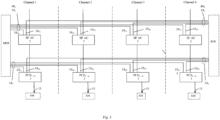
- Figure 6 shows structure of links via SF IOB bus of a group of 4 stations PCS 1 - 4 of safety channel 1 (4-channel safety system) with SF AC controller of this safety channel and with SF AC controllers of the other 3 safety channels.
- Communications of PCM modules 23 1 - 23 e with the normal operation system is implemented using redundant interface modules IMN 1 20 1 , IMN 2 20 2 , redundant bus NO IOB 1 19 1 , NO IOB 2 , via which modules IMN 1 , IMN 2 send commands to the PCM modules for generating the AM actuator control signals and reading the AM status received from the AC controller, and poll the "good / bad" status of the PCM modules. Based on the results of the polling, modules IMN 1 20 1 , IMN 2 20 2 generate generalized discrete state-of-health signals of the IOS station through the contacts of signal relays.
- Figure 7 shows arrangement of safety feature hardware, normal operation hardware and communication with AM control centers in PCM modules using block diagram of PCM module.
- PCM module executes AM control following initiating commands from several control centers: from SF AC controller via communication lines 28 of SF IOB bus; from normal operation controller AC via redundant buses ENL 1 10 1 , ENL 2 10 2 and NO IOB 1 19 1 , NO IOB 2 19 2 ( Figures 5 and 7 ); from MCR via wire lines 13 1 and from ECR via wire lines 13 2 . Via said links, transmission of PCM and AM state is executed, respectively, to SF AC, AC, MCR and ECR.
- AM control commands when initiated by commands from SF AC, MCR and ECR - in safety feature programmable logic circuits SF PLC 30 , and when initiated by commands from AC, MCR and ECR - in normal operation processor CPU 31.
- AM control commands from SF PLC 30, CPU processor 31 come to PLC of priority control logic PCL PLC 32 , where a command to be sent to AM is generated.
- Normal operation processor CPU 31 executes based on commands from normal operation automation controller AC and together with it the functions of automatic control of actuation mechanisms in the normal operation system if there is no emergency situation, and functions of controlling the commands sent to AM from SF AC, receiving data of state of AM controlled from SF AC, and transmitting this data to AC normal operation controller via NO IOB and ENL buses for evaluation by it of NPP and safety channel state.
- SF AC and AC interrogate the state of commands sent to AM. And here AC controller inquires for the state of its commands sent to AM, and of commands sent to AM by SF AC controller.
- the AM state signals come to MCR, ECR, and via PCL PLC 32 , SF PLC 30 and CPU processor 31 - to automation controllers, respectively, SF AC and AC.
- AC controller receives the AM state signals both when sending to AM its own commands, and when the commands are sent to AM by SF AC controller.
- Figure 8 shows structure of SF AC automation controller using the example of channel 1 of 4-channel safety system and scheme of communications of this controller and SF AC controllers of other safety channels with the IOS and PCS stations.
- the IOS and PCS stations In order to optimize the communications of SF AC with the IOS and PCS stations, they are combined into groups of 4 stations of the same name per group in accordance with the placement of these stations made in the form of standard crates, in instrument cabinets, 4 stations per cabinet.
- Automation controllers SF AC of 4 safety channels are located in 4 separate cabinets.
- Automation controller SF AC is comprised of automation processor module SF APM 35 and 11 communication modules - branch modules BM-4 36 1-11 , each having 4 branches.
- Three first modules BM-4 36 1-3 provide connection to the SF AC controller of up to 3 groups of IOB stations in each safety channel, or of up to 12 IOB stations.
- Eight next modules BM-4 4-11 in each safety channel provide connection to the SF AC controller of up to 32 groups of PCS stations or of up to 128 PCS stations.
- Each BM-4 module provides connection of up to 4 groups of PCS stations.
- Automation processor module SF APM 35 of controller SF AC receives via bus SF IOB 9 digital values of process parameters from MCP modules of IOB 1-n stations of its safety channel, processes them and, when an emergency is detected, in accordance with safety algorithms, generates and outputs via bus SF IOB 9 into PCM modules of PCS 1 - m stations of its own and other safety channels commands for controlling the protective actions to be selected for execution by the VM voting communication modules according to the voting principle '2 out of 4', Figure 6 , 8 .
- the SF APM 35 module exchanges data with the SF APM modules of the 2nd, 3rd and 4th safety channels, respectively, via the IPI 8 12 , 8 13 , 8 14 interprocessor interfaces and performs majority processing of data received from the IOS stations of all safety channels according to the '2 of 4' rule.
- the processor module Via the communication interfaces of the SF APM module of the 1st safety channel with the MCR - IPI 1 14 11 and with ECR - IPI 2 14 21 , the processor module receives remote control commands from the MCR and ECR and transmits to the the MCR and ECR diagnostic information about execution of protection algorithms and status of priority control equipment and actuation mechanisms.
- the SF APM module transmits the diagnostic information of the safety system to the normal operation system.
- the processor module APM executes reception of data from IOS stations and transmission of commands and data to PCS stations: via lines of bus SF IOB 37 1 - 37 11 communication, respectively, with communication modules BM-4 36 1 - 36 11 , and further via 4 communication lines 18 1 - 18 4 3 of 3 modules BM-4 1-3 with IOB stations 1-4 of 3 groups or with 12 IOB stations and via 4 sets of communication lines 26 11 - 26 14 , 26 21 - 26 24 , 26 31 - 26 34 , 26 41 - 26 44 of 8 modules BM-4 4-11 of all safety channels with 32 groups of CSS 1-4 stations or with 128 PCS stations.
- Layout of CSS stations by 4 stations per cabinet in accordance with the number of safety channels ensures optimization of a large number of channel and inter-channel communications via the input / output bus SF IOB between the SF AC controllers and the PCS stations in connection with the fundamental decision to architect the bus based on 'point-to-point' interfaces with full-duplex command and data transmission mode and locate VM voting communication modules in the lower end nodes of the bus.
- Optimization consists in reducing the cable connections between the SF AC cabinets of four channels and each of the 32 PCS cabinets to 4 minimum required, and in implementing inter-channel communications for voting in each of a cabinet's 4 PCS stations according to the '2 out of 4' principle by means of communication modules VCM , VM and additional 'point-to-point' type cable connections inside the cabinets according to the scheme, Fig. 6 , which are shorter and better protected than the cable connections between the cabinets.
Landscapes
- Engineering & Computer Science (AREA)
- Physics & Mathematics (AREA)
- General Engineering & Computer Science (AREA)
- Plasma & Fusion (AREA)
- High Energy & Nuclear Physics (AREA)
- Chemical & Material Sciences (AREA)
- Chemical Kinetics & Catalysis (AREA)
- Business, Economics & Management (AREA)
- Emergency Management (AREA)
- General Physics & Mathematics (AREA)
- Automation & Control Theory (AREA)
- Safety Devices In Control Systems (AREA)
Claims (4)
- Sicherheitssteuerungssystem zur Verwendung in Kernkraftwerken, umfassend:
eine Vielzahl von identischen Sicherheitskanälen, wobei jeder Kanal Eingangs-Ausgangsstationen von Prozesssignalen EAS1-n (1), Prioritätssteuerungsstationen von Aktoren PSS1-m (3), die mit der Hauptsteuerzentrale HSZ und der Ersatzsteuerzentrale ESZ verbunden sind, die Sicherheitsautomatisierungssteuerung SAS (2), einen Sicherheits-Eingangs-Ausgangsbus SEAB (9) zum Datenaustausch der SAS mit den Stationen EAS1-n (1) und PSS1-m (3) und mit anderen Sicherheitskanälen über Duplex-Lichtwellenleiterverbindungen querverbunden ist, dadurch gekennzeichnet, dass die Station EASi-n (1) Module zur Kommunikation mit dem Prozess und ein Kommunikationsmodul MSP1-k (15) - einen Kommunikationsschnittstellenkonverter KSK (16) des Busses SEAB (9) enthält; die Station PSS1-m (3) Prioritätssteuerungsmodule der Aktoren PSM1-e (23) und Kommunikationsmodulen enthält: ein Votierungskommunikationsmodul VKM (25) und ein Votierungsmodul VM (24) des Busses SEAB (9); SAS (2) ein Sicherheitsautomatisierungsprozessormodul SAPM (35) und Kommunikationsmodule - Verzweigungsmodule VM1-p (36) des Busses SEAB (9) enthält; Automatisierungssteuerungen SAS (2) aller Sicherheitskanäle über den auf der Basis einer geschalteten Ethernet-Schnittstelle, der Ringstruktur der Netzwerk-Switch-Verbindung und des Kommunikationsprotokolls der Datenebene aufgebauten redundanten Bus EN (5) mit dem Normalbetriebssystem verbunden sind; jeder Sicherheitskanal zusätzlich Normalbetrieb-Automatisierungssteuerungen AS1-s (4) enthält, die über die auf der Basis einer geschalteten Ethernet-Schnittstelle, der Ringstruktur der Netzwerk-Switch-Verbindung und des Kommunikationsprotokolls der Datenebene aufgebauten redundanten Normalbetrieb-Busse ENL (10) mit den Stationen EASi-n (1), PSS1-m (3) und über den redundanten Normalbetrieb-Bus EN (5) mit dem Normalbetriebssystem verbunden sind; die Normalbetrieb-Automatisierungssteuerungen AS (4), die in die Stationen EAS1-n (1) und PSS1-m (3) eingebaute Kommunikationsmittel AS mit dem Modul MSP1-k (15) und den Modulen PSM (23) sowie die in das Modul MSP1-k (15) und die Module PSM (23) eingebaute Normalbetrieb-Software und -Hardware auf der Grundlage unterschiedlicher Hardware- und Softwareplattformen aufgebaut sind; die Stationen EAS1-n (1), PSS1-m (3), die Automatisierungssteuerung SAS (2) und die Stromversorgungs- und Kommunikationseinrichtungen des Sicherheitssystems eingebaute Selbsttest- und Selbstüberwachungswerkzeuge enthalten, die an den Ausgängen binäre Signale des Zustands der entsprechenden Einrichtungen "fehlerfrei/fehlerhaft" erzeugen, die am NB AS ankommen, wo die Signale verarbeitet und über den Bus EN (5) an die obere Steuerungsebene des Normalbetriebssystems übertragen werden, wobei in den Stationen EAS1-n (1) das Kommunikationsmodul PIK (16) des Busses SEAB (9) über separate Kommunikationsleitungen des SEAB mit der Automatisierungssteuerung SAS (2) des Sicherheitskanals und jedem Modul MSP1-k (15) dieser Station verbunden ist. - Sicherheitssteuerungssystem zur Verwendung in Kernkraftwerken nach Anspruch 1, dadurch gekennzeichnet, dass jede Station EASi-n (1) zwei redundante Normalbetrieb-Schnittstellenmodule NSM (20) umfasst, die über einen redundanten Bus ENL (10) mit der Normalbetrieb-Automatisierungssteuerung NB AS (4) verbunden sind; jedes Modul MSP1-k (15) einen integrierten separaten Normalbetriebsprozessor umfasst, der über eine separate Punkt-zu-Punkt-Seriell-Duplex-Schnittstellenleitung des Normalbetrieb-Busses NB EAB (19) mit jedem der 2 Normalbetrieb-Module NSM (20) verbunden ist.
- Sicherheitssteuerungssystem zur Verwendung in Kernkraftwerken nach Anspruch 1, dadurch gekennzeichnet, dass die Stationen PSS1-m (3) in jedem Sicherheitskanal zu Gruppen von N Stationen zusammengefasst sind; die Anzahl der Stationen PSS (3) durch die Anzahl der Sicherheitskanäle bestimmt ist; die erste Station PSS1 (3) der Gruppe über die Kommunikationsleitung SEAB mit der Automatisierungssteuerung SAS (2) ihres Sicherheitskanals verbunden ist; die anderen Stationen PSS2-N (3) der Gruppe mit den Automatisierungssteuerungen SAS (2) anderer Sicherheitskanäle 2-N verbunden sind; das Kommunikationsmodul VKM (25) jeder Station PSS1-m (3) mit dem Votierungskommunikationsmodul durch den Mehrheitsalgorithmus "2 aus N" des VM (24) seiner Station PSS1-m (3) und den Kommunikationsmodulen VG (24) anderer Stationen PSS1-m (3) der Gruppe verbunden ist; das Kommunikationsmodul VM (24) jeder Station PSS1-m (3) über die Kommunikationsleitungen SEAB mit den Prioritätssteuerungsmodulen PSM1-e (23) verbunden ist.
- Sicherheitssteuerungssystem zur Verwendung in Kernkraftwerken nach Anspruch 3, dadurch gekennzeichnet, dass jede Station PSS1-m (3) zwei redundante Normalbetrieb-Schnittstellenmodule NSM (20) umfasst, die über den redundanten Bus ENL (10) mit der Normalbetriebs-Automatisierungssteuerung NB AS (4) verbunden sind; jedes Modul PSM1-e (23) einen integrierten separaten Normalbetriebsprozessor umfasst, der über eine separate Punkt-zu-Punkt-Seriell-Duplex-Schnittstellenleitung des Normalbetrieb-Busses NB EAB (19) mit jedem der 2 Normalbetrieb-Module NSM (20) verbunden ist.
Applications Claiming Priority (2)
| Application Number | Priority Date | Filing Date | Title |
|---|---|---|---|
| RU2015125046/08A RU2598599C1 (ru) | 2015-06-25 | 2015-06-25 | Управляющая система безопасности атомной электростанции |
| PCT/RU2016/000356 WO2016209114A1 (ru) | 2015-06-25 | 2016-06-10 | Управляющая система безопасности атомной электростанции |
Publications (3)
| Publication Number | Publication Date |
|---|---|
| EP3316261A1 EP3316261A1 (de) | 2018-05-02 |
| EP3316261A4 EP3316261A4 (de) | 2019-04-17 |
| EP3316261B1 true EP3316261B1 (de) | 2023-12-27 |
Family
ID=57018427
Family Applications (1)
| Application Number | Title | Priority Date | Filing Date |
|---|---|---|---|
| EP16814795.7A Active EP3316261B1 (de) | 2015-06-25 | 2016-06-10 | Steuerungssystem zur sicherheit eines kernkraftwerks |
Country Status (6)
| Country | Link |
|---|---|
| EP (1) | EP3316261B1 (de) |
| KR (1) | KR102333907B1 (de) |
| CN (1) | CN107924722B (de) |
| HU (1) | HUE066091T2 (de) |
| RU (1) | RU2598599C1 (de) |
| WO (1) | WO2016209114A1 (de) |
Families Citing this family (3)
| Publication number | Priority date | Publication date | Assignee | Title |
|---|---|---|---|---|
| EP3576103A4 (de) * | 2017-01-24 | 2020-08-19 | China Techenergy Co., Ltd | Verfahren zur verwaltung der priorität eines kernkraftwerks |
| CN110398901B (zh) * | 2019-04-28 | 2023-04-18 | 北京广利核系统工程有限公司 | 核电站dcs仿真机失电仿真方法及装置 |
| CN111555941B (zh) * | 2020-04-30 | 2021-12-17 | 中国科学院长春光学精密机械与物理研究所 | 一种通信协议测试驱动数据自动生成方法 |
Family Cites Families (16)
| Publication number | Priority date | Publication date | Assignee | Title |
|---|---|---|---|---|
| US5745539A (en) * | 1995-11-14 | 1998-04-28 | Westinghouse Electric Corporation | Apparatus and method for prioritization of multiple commands in an instrumentation and control system |
| US6049578A (en) * | 1997-06-06 | 2000-04-11 | Abb Combustion Engineering Nuclear Power, Inc. | Digital plant protection system |
| US5984504A (en) * | 1997-06-11 | 1999-11-16 | Westinghouse Electric Company Llc | Safety or protection system employing reflective memory and/or diverse processors and communications |
| KR100265321B1 (ko) * | 1997-11-28 | 2000-09-15 | 윤덕용 | 가압경수로형원자로보호계통용동적안전시스템 |
| RU2150756C1 (ru) * | 1999-01-28 | 2000-06-10 | Грибов Алексей Алексеевич | Способ сбора и обработки сигналов в системе контроля активной зоны ядерного реактора и система для его осуществления |
| CN1119819C (zh) * | 2000-11-10 | 2003-08-27 | 清华大学 | 基于硬件和软件并行处理的反应堆数字化保护系统 |
| KR100848881B1 (ko) * | 2006-08-07 | 2008-07-29 | 삼창기업 주식회사 | 디지털 원자로 보호 시스템 |
| UA78477C2 (en) * | 2006-08-28 | 2007-03-15 | Yevhenii Stepanovych Bakhmach | Control digital safety system of nuclear station and method for providing the safety system parameters |
| KR100857145B1 (ko) * | 2007-02-08 | 2008-09-05 | 한국원자력연구원 | 통합 디지털 공학적 안전설비-기기제어계통 및 그 방법 |
| US8117512B2 (en) * | 2008-02-06 | 2012-02-14 | Westinghouse Electric Company Llc | Failure detection and mitigation in logic circuits |
| US20110313580A1 (en) * | 2010-06-17 | 2011-12-22 | Levgenii Bakhmach | Method and platform to implement safety critical systems |
| RU2431174C1 (ru) * | 2010-08-20 | 2011-10-10 | Федеральное государственное унитарное предприятие "Всероссийский научно-исследовательский институт автоматики им. Н.Л. Духова" (ФГУП "ВНИИА") | Комплекс резервируемых программно-аппаратных средств автоматизации контроля и управления |
| KR101244015B1 (ko) * | 2011-09-09 | 2013-03-15 | 한국수력원자력 주식회사 | 독립적 다중화 구조를 갖는 통합원전안전계통 및 구성 방법 |
| CN102426863B (zh) * | 2011-10-31 | 2015-12-16 | 中广核工程有限公司 | 核电站反应堆停堆信号传输系统和方法 |
| RU2487372C1 (ru) * | 2012-01-10 | 2013-07-10 | Федеральное государственное унитарное предприятие "Научно-исследовательский технологический институт имени А.П. Александрова" | Система дистанционного радиационного контроля |
| CN104409123B (zh) * | 2014-11-15 | 2017-06-16 | 北京广利核系统工程有限公司 | 一种核电站优先级管理系统 |
-
2015
- 2015-06-25 RU RU2015125046/08A patent/RU2598599C1/ru active
-
2016
- 2016-06-10 HU HUE16814795A patent/HUE066091T2/hu unknown
- 2016-06-10 KR KR1020177037691A patent/KR102333907B1/ko active IP Right Grant
- 2016-06-10 CN CN201680037434.6A patent/CN107924722B/zh active Active
- 2016-06-10 EP EP16814795.7A patent/EP3316261B1/de active Active
- 2016-06-10 WO PCT/RU2016/000356 patent/WO2016209114A1/ru active Application Filing
Also Published As
| Publication number | Publication date |
|---|---|
| KR20180036920A (ko) | 2018-04-10 |
| RU2598599C1 (ru) | 2016-09-27 |
| EP3316261A4 (de) | 2019-04-17 |
| EP3316261A1 (de) | 2018-05-02 |
| WO2016209114A1 (ru) | 2016-12-29 |
| CN107924722A (zh) | 2018-04-17 |
| WO2016209114A9 (ru) | 2017-02-02 |
| KR102333907B1 (ko) | 2021-12-03 |
| HUE066091T2 (hu) | 2024-07-28 |
| CN107924722B (zh) | 2021-11-23 |
Similar Documents
| Publication | Publication Date | Title |
|---|---|---|
| EP3316262B1 (de) | Sicherheitssteuerungssystem für ein kernkraftwerk | |
| EP1010044B1 (de) | Sicherheits- oder schutzsystem mit gespiegeltem speicher und/oder diversen prozessoren und übertragungen | |
| CN102096401B (zh) | 基于现场总线和arm处理器的冗余容错安全仪表系统 | |
| US20180211734A1 (en) | Reactor protection-processor-to-reactor-trip breaker interface and method for operating the same | |
| CN105575448A (zh) | 核电站反应堆保护系统及其中的安全控制方法 | |
| EP3316261B1 (de) | Steuerungssystem zur sicherheit eines kernkraftwerks | |
| KR100848881B1 (ko) | 디지털 원자로 보호 시스템 | |
| EP3316260A1 (de) | Sicherheitskontrollsystem für kernkraftwerk | |
| CN108287519B (zh) | 用于质子治疗设备安全联锁的逻辑结构和实现方法 | |
| CN111681792B (zh) | Atwt控制装置及核电设备 | |
| US6473479B1 (en) | Dual optical communication network for class 1E reactor protection systems | |
| KR101298459B1 (ko) | Fpga 기반 제어기의 버스 구조 | |
| Suh et al. | Developing architecture for upgrading I&C systems of an operating nuclear power plant using a quality attribute-driven design method | |
| Lee et al. | Risk assessment of safety-critical data communication in digital safety feature control system | |
| CN105867316B (zh) | 基于Modbus协议的电站汽机电液控制系统的整体监控系统 | |
| CN211529626U (zh) | 一种核动力堆dcs架构 | |
| CA2304438C (en) | Safety or protection system employing reflective memory and/or diverse processors and communications | |
| Kim et al. | Implementation of Multiloop Control for the Plant Control System in Improved Korean Standard Nuclear Power Plant (KSNP+) | |
| Gomez et al. | Application of DCS to new build CANDU designs using the G-HIACS vSAFE platform |
Legal Events
| Date | Code | Title | Description |
|---|---|---|---|
| STAA | Information on the status of an ep patent application or granted ep patent |
Free format text: STATUS: THE INTERNATIONAL PUBLICATION HAS BEEN MADE |
|
| PUAI | Public reference made under article 153(3) epc to a published international application that has entered the european phase |
Free format text: ORIGINAL CODE: 0009012 |
|
| STAA | Information on the status of an ep patent application or granted ep patent |
Free format text: STATUS: REQUEST FOR EXAMINATION WAS MADE |
|
| 17P | Request for examination filed |
Effective date: 20171227 |
|
| AK | Designated contracting states |
Kind code of ref document: A1 Designated state(s): AL AT BE BG CH CY CZ DE DK EE ES FI FR GB GR HR HU IE IS IT LI LT LU LV MC MK MT NL NO PL PT RO RS SE SI SK SM TR |
|
| AX | Request for extension of the european patent |
Extension state: BA ME |
|
| DAV | Request for validation of the european patent (deleted) | ||
| DAX | Request for extension of the european patent (deleted) | ||
| A4 | Supplementary search report drawn up and despatched |
Effective date: 20190315 |
|
| RIC1 | Information provided on ipc code assigned before grant |
Ipc: G05B 9/03 20060101ALI20190311BHEP Ipc: G21C 7/36 20060101AFI20190311BHEP Ipc: G21D 3/04 20060101ALI20190311BHEP |
|
| STAA | Information on the status of an ep patent application or granted ep patent |
Free format text: STATUS: EXAMINATION IS IN PROGRESS |
|
| 17Q | First examination report despatched |
Effective date: 20200717 |
|
| STAA | Information on the status of an ep patent application or granted ep patent |
Free format text: STATUS: EXAMINATION IS IN PROGRESS |
|
| STAA | Information on the status of an ep patent application or granted ep patent |
Free format text: STATUS: EXAMINATION IS IN PROGRESS |
|
| REG | Reference to a national code |
Ref document number: 602016085022 Country of ref document: DE Ref country code: DE Ref legal event code: R079 Free format text: PREVIOUS MAIN CLASS: G21C0007360000 Ipc: G05B0009030000 |
|
| GRAP | Despatch of communication of intention to grant a patent |
Free format text: ORIGINAL CODE: EPIDOSNIGR1 |
|
| STAA | Information on the status of an ep patent application or granted ep patent |
Free format text: STATUS: GRANT OF PATENT IS INTENDED |
|
| RIC1 | Information provided on ipc code assigned before grant |
Ipc: G21D 3/04 20060101ALI20230707BHEP Ipc: G21C 7/36 20060101ALI20230707BHEP Ipc: G05B 9/03 20060101AFI20230707BHEP |
|
| INTG | Intention to grant announced |
Effective date: 20230728 |
|
| GRAS | Grant fee paid |
Free format text: ORIGINAL CODE: EPIDOSNIGR3 |
|
| GRAA | (expected) grant |
Free format text: ORIGINAL CODE: 0009210 |
|
| STAA | Information on the status of an ep patent application or granted ep patent |
Free format text: STATUS: THE PATENT HAS BEEN GRANTED |
|
| AK | Designated contracting states |
Kind code of ref document: B1 Designated state(s): AL AT BE BG CH CY CZ DE DK EE ES FI FR GB GR HR HU IE IS IT LI LT LU LV MC MK MT NL NO PL PT RO RS SE SI SK SM TR |
|
| REG | Reference to a national code |
Ref country code: GB Ref legal event code: FG4D |
|
| REG | Reference to a national code |
Ref country code: CH Ref legal event code: EP |
|
| REG | Reference to a national code |
Ref country code: DE Ref legal event code: R096 Ref document number: 602016085022 Country of ref document: DE |
|
| REG | Reference to a national code |
Ref country code: IE Ref legal event code: FG4D |
|
| PG25 | Lapsed in a contracting state [announced via postgrant information from national office to epo] |
Ref country code: GR Free format text: LAPSE BECAUSE OF FAILURE TO SUBMIT A TRANSLATION OF THE DESCRIPTION OR TO PAY THE FEE WITHIN THE PRESCRIBED TIME-LIMIT Effective date: 20240328 |
|
| REG | Reference to a national code |
Ref country code: LT Ref legal event code: MG9D |
|
| PG25 | Lapsed in a contracting state [announced via postgrant information from national office to epo] |
Ref country code: LT Free format text: LAPSE BECAUSE OF FAILURE TO SUBMIT A TRANSLATION OF THE DESCRIPTION OR TO PAY THE FEE WITHIN THE PRESCRIBED TIME-LIMIT Effective date: 20231227 |
|
| PG25 | Lapsed in a contracting state [announced via postgrant information from national office to epo] |
Ref country code: ES Free format text: LAPSE BECAUSE OF FAILURE TO SUBMIT A TRANSLATION OF THE DESCRIPTION OR TO PAY THE FEE WITHIN THE PRESCRIBED TIME-LIMIT Effective date: 20231227 |
|
| PG25 | Lapsed in a contracting state [announced via postgrant information from national office to epo] |
Ref country code: LT Free format text: LAPSE BECAUSE OF FAILURE TO SUBMIT A TRANSLATION OF THE DESCRIPTION OR TO PAY THE FEE WITHIN THE PRESCRIBED TIME-LIMIT Effective date: 20231227 Ref country code: GR Free format text: LAPSE BECAUSE OF FAILURE TO SUBMIT A TRANSLATION OF THE DESCRIPTION OR TO PAY THE FEE WITHIN THE PRESCRIBED TIME-LIMIT Effective date: 20240328 Ref country code: FI Free format text: LAPSE BECAUSE OF FAILURE TO SUBMIT A TRANSLATION OF THE DESCRIPTION OR TO PAY THE FEE WITHIN THE PRESCRIBED TIME-LIMIT Effective date: 20231227 Ref country code: ES Free format text: LAPSE BECAUSE OF FAILURE TO SUBMIT A TRANSLATION OF THE DESCRIPTION OR TO PAY THE FEE WITHIN THE PRESCRIBED TIME-LIMIT Effective date: 20231227 Ref country code: BG Free format text: LAPSE BECAUSE OF FAILURE TO SUBMIT A TRANSLATION OF THE DESCRIPTION OR TO PAY THE FEE WITHIN THE PRESCRIBED TIME-LIMIT Effective date: 20240327 |
|
| REG | Reference to a national code |
Ref country code: NL Ref legal event code: MP Effective date: 20231227 |
|
| REG | Reference to a national code |
Ref country code: AT Ref legal event code: MK05 Ref document number: 1645096 Country of ref document: AT Kind code of ref document: T Effective date: 20231227 |
|
| PG25 | Lapsed in a contracting state [announced via postgrant information from national office to epo] |
Ref country code: NL Free format text: LAPSE BECAUSE OF FAILURE TO SUBMIT A TRANSLATION OF THE DESCRIPTION OR TO PAY THE FEE WITHIN THE PRESCRIBED TIME-LIMIT Effective date: 20231227 |
|
| PG25 | Lapsed in a contracting state [announced via postgrant information from national office to epo] |
Ref country code: SE Free format text: LAPSE BECAUSE OF FAILURE TO SUBMIT A TRANSLATION OF THE DESCRIPTION OR TO PAY THE FEE WITHIN THE PRESCRIBED TIME-LIMIT Effective date: 20231227 Ref country code: RS Free format text: LAPSE BECAUSE OF FAILURE TO SUBMIT A TRANSLATION OF THE DESCRIPTION OR TO PAY THE FEE WITHIN THE PRESCRIBED TIME-LIMIT Effective date: 20231227 Ref country code: NO Free format text: LAPSE BECAUSE OF FAILURE TO SUBMIT A TRANSLATION OF THE DESCRIPTION OR TO PAY THE FEE WITHIN THE PRESCRIBED TIME-LIMIT Effective date: 20240327 Ref country code: NL Free format text: LAPSE BECAUSE OF FAILURE TO SUBMIT A TRANSLATION OF THE DESCRIPTION OR TO PAY THE FEE WITHIN THE PRESCRIBED TIME-LIMIT Effective date: 20231227 Ref country code: LV Free format text: LAPSE BECAUSE OF FAILURE TO SUBMIT A TRANSLATION OF THE DESCRIPTION OR TO PAY THE FEE WITHIN THE PRESCRIBED TIME-LIMIT Effective date: 20231227 Ref country code: HR Free format text: LAPSE BECAUSE OF FAILURE TO SUBMIT A TRANSLATION OF THE DESCRIPTION OR TO PAY THE FEE WITHIN THE PRESCRIBED TIME-LIMIT Effective date: 20231227 |
|
| PG25 | Lapsed in a contracting state [announced via postgrant information from national office to epo] |
Ref country code: IS Free format text: LAPSE BECAUSE OF FAILURE TO SUBMIT A TRANSLATION OF THE DESCRIPTION OR TO PAY THE FEE WITHIN THE PRESCRIBED TIME-LIMIT Effective date: 20240427 |
|
| PG25 | Lapsed in a contracting state [announced via postgrant information from national office to epo] |
Ref country code: AT Free format text: LAPSE BECAUSE OF FAILURE TO SUBMIT A TRANSLATION OF THE DESCRIPTION OR TO PAY THE FEE WITHIN THE PRESCRIBED TIME-LIMIT Effective date: 20231227 Ref country code: CZ Free format text: LAPSE BECAUSE OF FAILURE TO SUBMIT A TRANSLATION OF THE DESCRIPTION OR TO PAY THE FEE WITHIN THE PRESCRIBED TIME-LIMIT Effective date: 20231227 |
|
| REG | Reference to a national code |
Ref country code: HU Ref legal event code: AG4A Ref document number: E066091 Country of ref document: HU |
|
| PG25 | Lapsed in a contracting state [announced via postgrant information from national office to epo] |
Ref country code: SK Free format text: LAPSE BECAUSE OF FAILURE TO SUBMIT A TRANSLATION OF THE DESCRIPTION OR TO PAY THE FEE WITHIN THE PRESCRIBED TIME-LIMIT Effective date: 20231227 |
|
| PG25 | Lapsed in a contracting state [announced via postgrant information from national office to epo] |
Ref country code: SM Free format text: LAPSE BECAUSE OF FAILURE TO SUBMIT A TRANSLATION OF THE DESCRIPTION OR TO PAY THE FEE WITHIN THE PRESCRIBED TIME-LIMIT Effective date: 20231227 Ref country code: SK Free format text: LAPSE BECAUSE OF FAILURE TO SUBMIT A TRANSLATION OF THE DESCRIPTION OR TO PAY THE FEE WITHIN THE PRESCRIBED TIME-LIMIT Effective date: 20231227 Ref country code: RO Free format text: LAPSE BECAUSE OF FAILURE TO SUBMIT A TRANSLATION OF THE DESCRIPTION OR TO PAY THE FEE WITHIN THE PRESCRIBED TIME-LIMIT Effective date: 20231227 Ref country code: IT Free format text: LAPSE BECAUSE OF FAILURE TO SUBMIT A TRANSLATION OF THE DESCRIPTION OR TO PAY THE FEE WITHIN THE PRESCRIBED TIME-LIMIT Effective date: 20231227 Ref country code: IS Free format text: LAPSE BECAUSE OF FAILURE TO SUBMIT A TRANSLATION OF THE DESCRIPTION OR TO PAY THE FEE WITHIN THE PRESCRIBED TIME-LIMIT Effective date: 20240427 Ref country code: EE Free format text: LAPSE BECAUSE OF FAILURE TO SUBMIT A TRANSLATION OF THE DESCRIPTION OR TO PAY THE FEE WITHIN THE PRESCRIBED TIME-LIMIT Effective date: 20231227 Ref country code: CZ Free format text: LAPSE BECAUSE OF FAILURE TO SUBMIT A TRANSLATION OF THE DESCRIPTION OR TO PAY THE FEE WITHIN THE PRESCRIBED TIME-LIMIT Effective date: 20231227 Ref country code: AT Free format text: LAPSE BECAUSE OF FAILURE TO SUBMIT A TRANSLATION OF THE DESCRIPTION OR TO PAY THE FEE WITHIN THE PRESCRIBED TIME-LIMIT Effective date: 20231227 |
|
| PG25 | Lapsed in a contracting state [announced via postgrant information from national office to epo] |
Ref country code: PT Free format text: LAPSE BECAUSE OF FAILURE TO SUBMIT A TRANSLATION OF THE DESCRIPTION OR TO PAY THE FEE WITHIN THE PRESCRIBED TIME-LIMIT Effective date: 20240429 Ref country code: PL Free format text: LAPSE BECAUSE OF FAILURE TO SUBMIT A TRANSLATION OF THE DESCRIPTION OR TO PAY THE FEE WITHIN THE PRESCRIBED TIME-LIMIT Effective date: 20231227 |
|
| PGFP | Annual fee paid to national office [announced via postgrant information from national office to epo] |
Ref country code: TR Payment date: 20240607 Year of fee payment: 9 Ref country code: HU Payment date: 20240605 Year of fee payment: 9 |