EP3316260A1 - Safety control system for nuclear power plant - Google Patents
Safety control system for nuclear power plant Download PDFInfo
- Publication number
- EP3316260A1 EP3316260A1 EP16814794.0A EP16814794A EP3316260A1 EP 3316260 A1 EP3316260 A1 EP 3316260A1 EP 16814794 A EP16814794 A EP 16814794A EP 3316260 A1 EP3316260 A1 EP 3316260A1
- Authority
- EP
- European Patent Office
- Prior art keywords
- subchannel
- iob
- communication
- safety
- stations
- Prior art date
- Legal status (The legal status is an assumption and is not a legal conclusion. Google has not performed a legal analysis and makes no representation as to the accuracy of the status listed.)
- Granted
Links
Images





Classifications
-
- G—PHYSICS
- G05—CONTROLLING; REGULATING
- G05B—CONTROL OR REGULATING SYSTEMS IN GENERAL; FUNCTIONAL ELEMENTS OF SUCH SYSTEMS; MONITORING OR TESTING ARRANGEMENTS FOR SUCH SYSTEMS OR ELEMENTS
- G05B19/00—Program-control systems
- G05B19/02—Program-control systems electric
- G05B19/04—Program control other than numerical control, i.e. in sequence controllers or logic controllers
- G05B19/048—Monitoring; Safety
-
- G—PHYSICS
- G21—NUCLEAR PHYSICS; NUCLEAR ENGINEERING
- G21C—NUCLEAR REACTORS
- G21C7/00—Control of nuclear reaction
- G21C7/36—Control circuits
-
- G—PHYSICS
- G05—CONTROLLING; REGULATING
- G05B—CONTROL OR REGULATING SYSTEMS IN GENERAL; FUNCTIONAL ELEMENTS OF SUCH SYSTEMS; MONITORING OR TESTING ARRANGEMENTS FOR SUCH SYSTEMS OR ELEMENTS
- G05B9/00—Safety arrangements
- G05B9/02—Safety arrangements electric
- G05B9/03—Safety arrangements electric with multiple-channel loop, i.e. redundant control systems
-
- G—PHYSICS
- G21—NUCLEAR PHYSICS; NUCLEAR ENGINEERING
- G21D—NUCLEAR POWER PLANT
- G21D3/00—Control of nuclear power plant
-
- Y—GENERAL TAGGING OF NEW TECHNOLOGICAL DEVELOPMENTS; GENERAL TAGGING OF CROSS-SECTIONAL TECHNOLOGIES SPANNING OVER SEVERAL SECTIONS OF THE IPC; TECHNICAL SUBJECTS COVERED BY FORMER USPC CROSS-REFERENCE ART COLLECTIONS [XRACs] AND DIGESTS
- Y02—TECHNOLOGIES OR APPLICATIONS FOR MITIGATION OR ADAPTATION AGAINST CLIMATE CHANGE
- Y02E—REDUCTION OF GREENHOUSE GAS [GHG] EMISSIONS, RELATED TO ENERGY GENERATION, TRANSMISSION OR DISTRIBUTION
- Y02E30/00—Energy generation of nuclear origin
- Y02E30/30—Nuclear fission reactors
Definitions
- the invention relates to automatics and computer engineering, and can be used in I&C systems of nuclear power plants (NPP) for constructing control safety systems (CSS) of NPP.
- NPP nuclear power plants
- CSS control safety systems
- a digital plant protection system is known ( U.S. Patent No. 6049578 , IPC G21C 7/36, published on April 11, 2000, analog), which consists of four identical processing & control channels that provide detection of a trip condition at a facility by means of comparison of measured parameter values with predetermined setpoints and execution of user-specified remedial actions in case the parameters are out-of-specification.
- Safety channels physically separated from one another, are cross-connected with each other by optical fiber communication paths. Each channel includes analog and digital sensors associated with this channel; analog-to-digital converters that provide at the output digital representation of the measured analog signals; a bistable processor; a coincidence logic processor, and a logic processor initiating actuation mechanisms (AM) and automatic safety features of a reactor.
- AM actuation mechanisms
- the bistable processor accepts digital values of measured signals of its own channel, convert them into the process-dependent parameters, checks measured parameters for deviation beyond the predetermined limits, generates for each parameter a binary sign of deviation, transmits these signs via optical fiber lines to other processing & control channels.
- the coincidence logic processor receives from the bistable processor of its channel the binary signs of parameters deviation for the signals of this channel, and receives via optical fiber lines from the other channels the binary signs of deviation for the respective parameters. For every parameter the coincidence logic processor checks receipt of signs of beyond-limit deviation of 2 out of 4 channels. If the coincidence processor detects deviation from the permissible values of the parameters for 2 out of 4 channels, then initiation logic processor generates needed signals for reactor trip and for actuation of digital safety features.
- the protection system has a major disadvantage due to the fact that safety channels are built using the same digital processing & control hardware and basic & system software. This can lead to common cause failures of all the channels of the protection system due to latent faults in programmable equipment and encapsulated errors of basic and system software.
- a digital control safety system (DCSS) of nuclear power plant together with a method of safety parameters provision is known ( RU patent No. 2356111 , IPC G21C7/36, published in 2009, prototype), which consists of three separate identical safety channels executing evaluation of a facility state by means of the analysis of the parameter values received from the process sensors and forming control protective actions in case of emergency situation.
- Physically separated safety channels are cross-connected with each other by optical fiber communication paths.
- Each channel includes an input device, comparator, control action generating device, lockout selection device, and actuation mechanisms control device.
- the input device executes input of analog signals of the process and their conversion into digital form.
- the comparator compares read out parameter values with pre-determined digital values and starts the device generating control signals, based on which the lockout selection device initiates generation of actuation mechanism control signals.
- This control safety system has a major disadvantage that consists in the fact that the safety channels have similar structure and are implemented using the same software & hardware, which can lead to common cause failure due to latent faults of digital equipment and encapsulated errors in basic and system software.
- This invention eliminates mentioned disadvantages.
- each channel includes process signal I/O stations IOS 1-n , actuation mechanism priority control stations PCS 1-m connected with the main control room MCR and emergency control room ECR, safety features automation controller (SF AC), safety feature I/O bus SF IOB for data exchange between SF AC and IOS/PCS stations, and is cross-connected with other safety channels by means of duplex optical fiber communication paths; I/O stations IOS; priority control stations PCS and safety feature automation controller SF AC of each safety channel contain two mutually independent software & hardware sets that form subchannel A and subchannel B built based on different hardware & software platforms; each subchannel executes all functions of a safety channel, each CSS channel contains controller SF AC A of subchannel A and controller SF AC B of subchannel B, each of which is connected, respectively, with SF AC A and SF AC B controllers of other safety channels via interprocessor interfaces IPI A and IPI B of 'point-to point'
- I/O station IOS contains modules of communication with the process MCP 1-k , and two communication modules - converters of interfaces: CIC A of SF IOB A bus and CIC B of SF IOB B bus, and here CIC A module, CIC B module are connected via one communication line of the module with its automation controller SF AC A,SF AC B and via separate communication lines with each MCP 1-k module; modules of communication with the process MCP 1-k of IOS station include processor of subchannel A and processor of subchannel B that are connected, respectively, via intra-station lines of SF IOB A and SF IOB B buses with communication modules CIC A and CIC B and via SF IOB A and SF IOB B buses are connected, respectively, to SF AC A controller of subchannel A and SF AC B controller of subchannel B.
- Each priority control station PCS contains priority control modules PCM 1-e , communication modules of SF IOB A bus of subchannel A and SF IOB B bus of subchannel B: voting communication modules VCM A, VCM B and voting modules VM A, VM B of input commands from N channels according to '2 out of 4' principle.
- each subchannel of a safety channel PCS stations are combined into groups of N stations; the number of PCS stations is determined by the number of safety channels; in subchannel A of each safety channel the first station of the group PCS 1 is connected by the SF IOB A communication line with SF AC A controller of its safety channel; the other stations PCS 2-N of the group are connected with SF AC A controllers of the other N-1 safety channels; communication module VCM A of each PCS station is connected with the voting communication module VM A of its PCS station and with communication modules VM A of the other PCS stations of the group; communication module VM A of each PCS station is connected via SF IOB A communication lines with priority control modules PCM 1-e ; and in subchannel B of each safety channel communication links of PCM modules of PCS stations of the group with automation controllers SF AC B of each safety channel are implemented similarly to communication links of subchannel A.
- Priority control modules PCM 1-e of PCS station contain safety feature programmable logic circuits (PLC) - SF PLC A of subchannel A and SF PLC B of subchannel B that are connected, respectively, via intra-station lines of SF IOB A and SF IOB B buses with communication modules VM A of subchannel A and VM B of subchannel B and via SF IOB A and SF IOB B buses are connected, respectively, to controllers SF AC A of subchannel A and SF AC B of subchannel B.
- PLC safety feature programmable logic circuits
- Automation controller SF AC A of subchannel A of each safety channel includes automation processor module APM A and p communication modules BM-4 A of SF IOB A bus connected via SF IOB A communication lines with processor modules SF APM A, with communication modules CIC A of I/O stations IOS 1-n and communication modules VCM A of priority control stations of their own safety channel and with communication modules VCM A of priority control stations PCS 1-m of the other safety channels; automation controller SF AC B of subchannel B of each safety channel is similar to subchannel A as to its configuration and links.
- Hardware & software sets of subchannel A and subchannel B that implement all functions of the safety channel are built based on processors and programmable logic circuits (PLC) differing in architecture, basic and system software, programming and hardware logic development tools, and meeting diversity requirements excluding common cause failures of all CSS channels due to encapsulated errors of software and latent defects of hardware.
- PLC programmable logic circuits
- Two hardware & software sets in each safety channel enhance system reliability also due to double redundancy of each channel equipment.
- I/O stations IOS 1-n of each safety channel receive analog and binary signals of the process, convert them into digital form, and transmit via safety I/O buses SF IOB A 7 a of subchannel A and SF IOB B 7 b of subchannel B to automation controllers of the safety channel, respectively, SF AC A 2 a of subchannel A and SF AC B 2 b of subchannel B.
- stations IOS Following commands of SF AC A 2 a and SF AC B 2 b , stations IOS also generate and send control signals for CPS.
- SF AC A 2 a and SF AC B 2 b controllers convert received digital values of analog and binary signals into the process parameters, transmit them via interprocessor interfaces, respectively, IPI 4 a and IPI 4 b to automation controllers SF AC A 2 a and SF AC B 2 b of the other safety channels, receive process parameters from these safety channels, and execute software-based selection of parameters for further processing according to majority algorithm '2 out of 4' at the first level of interchannel communications and majority redundancy.
- Automation controllers SF AC A 2 a and SF AC B 2 b compare selected according to the majority algorithm process parameters with the predetermined limits of nuclear power plant safe operation. Further processing of the process parameters received is executed at several stages of implementation of protection algorithms, including intermediate conversion of the results of processing, interchannel communications via IPI 4 a and IPI 4 b interfaces, and majority processing at every stage.
- SF AC A 2 a and SF AC B 2 b controllers detect an emergency situation as a result of analysis of input process parameters, they generate and send via SF IOB A 7 a and SF IOB A 7 b buses protective commands of AM control to the priority control stations PCS 1-m 3 of their safety channel and to PCS stations 3 of other safety channels at the second level of interchannel communications. If emergency situation requires reactor trip, then SF AC A 2 a and SF AC B 2 b generate and send via I/O buses, respectively, SF IOB A 7 a and SF IOB A 7 b to respective IOS stations control commands for CPS.
- Automation controllers SF AC A 2 a and SF AC B 2 b in the process of operation generate and send to the upper level of the normal operation system via redundant switched bus EN 5 of normal operation diagnostic information about execution of protection functions and the state of SF AC A 2 a and SF AC B 2 b , and IOS/PCS stations. Reception of information in SF AC A 2 a and SF AC B 2 b via EN bus from normal operation system is blocked.
- Priority control stations PCS 1-m 3 receive actuation mechanism control commands from SF AC A 2 a and SF AC B 2 b controllers of their own channel and of other safety channels via I/O buses SF IOB A 7 a and SF IOB A 7 b , and execute their hardware-based processing according to redundancy principle '2 out of 4' at the second level of interchannel communications.
- PCS 1-m stations 3 based on the commands selected according to majority algorithm '2 out of 4', generate control signals for actuation mechanisms AM 8 according to priorities of the control centers SF AC A 2 a and SF AC B 2 b .
- Control commands for AM 8 come to actuation mechanisms via gating circuits of PCS 1-m looped following the commands from automation controllers SF AC A 2 a and SF AC B 2 b .
- Automation controllers read generated for AM 8 commands and output control signals for AM 8 via feedback links of priority control logic of PC S 1-m stations and check whether prepared for sending to AM 8 and sent to AM 8 commands comply with the preset commands in order to exclude possibility of sending false control signals to actuation mechanisms AM 8 due to PCS faults.
- Safety channel stations PCS 1-m 3 also receive control commands from other control centers: the main control room MCR and emergency control room ECR, and generate control signals for AM 8 according to the priorities of the control centers.
- MCR and ECR are connected directly to PCS 1-m stations 3 of each safety channel via wire lines, and to SF AC A 2 a and SF AC B 2 b controllers via bus communication lines IPI 1 A 11 a1 , IPI 1 B 11 b1 and IPI 2 A 11 a2 , IPI 2 B 11 b2 built based on Ethernet 'point-to-point'-type interface and specific data-level communications protocol.
- Stations IOS 1-n 1 and PCS 1-m 3 contain two independent sets of subchannel A and subchannel B software & hardware meeting diversity principle and implementing together with the two automation controllers SF AC A 2 a of subchannel A and SF AC B 2 b of subchannel B separately all functions of the safety system channel.
- subchannels A and B are implemented in the form of two communication modules: CIC A 13 of SF IOB A bus 7 a of subchannel A and CIC B 13 of SF IOB B bus 7 b of subchannel B, and software & hardware of subchannels A and B integrated into MCP modules 12 1 - 12 k .
- CIC A and CIC B modules are connected, respectively, via communication lines of SF IOB A 13 and SF IOB B 17 of 'point-to-point' type of serial duplex interface with each MCP module 12 1 - 12 k , and via communication lines of SF IOB A bus 15 1 and SF IOB B 18 1 of 'point-to-point' type - with automation controllers, respectively, SF AC A of subchannel A and SF AC B of subchannel B.
- Communication modules CIC A 13 and CIC B 16 distribute commands and data coming via lines 15 1 and 18 1 from SF AC A and SF AC B controllers, respectively, to communication lines 14 and 17 with MCP modules, and concentrate data coming via lines 14 and 17 from MCP modules in lines 15 1 and 18 1 of IOS station communication with SF AC A and SF AC B. It means that via communication lines 15 1 and 18 1 of SF IOB A and SF IOB B an access to each MCP module of I/O station is implemented for data transmission and reception from SF AC.
- Modules of communication with the process MCP 12 1 - 12 k execute reception and reproduction of analog and binary signals of the process, conversion of input signals of the process into digital form and digital values of output signals into analog form, preprocessing of input signals, communication with SF AC A and SF AC B controllers via communication lines, respectively, 14 , 15 1 and 17 , 18 1 of buses SF IOB A 7 a and SF IOB B 7 b .
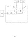
- FIG 4 shows block diagram of analog signal input module MCP demonstrating arrangement of subchannels A and B hardware in MCP modules.
- Built-in hardware of subchannels is implemented in the module in the form of two processors SF CPU A 21 of subchannel A and SF CPU B 22 of subchannel B connected, respectively, via buses SF IOB A 14 and SF IOB B 17 with communication modules CIC A 13 and CIC B 16 ( Figure 3 ), through which the access to these processors 21 and 22 from the side of SF AC A and SF AC B controllers is implemented via communication lines 15 and 18 ( Figure 3 ) for data exchange.
- Process signal comes in the analog signal input module MCP via input circuits 19 to the input of analog-to-digital converter ADC 20 that implements signal conversion into digital form.
- Processors SF CPU A 21 of subchannel A and SF CPU B 22 of subchannel B receive digital signal from ADC 20 output, execute its preprocessing and transmit it, respectively, via communication lines of SF IOB A 14 and SF IOB B 17 buses to communication modules CIC A 13 and CIC B 16 ( Figures 3 and 4 ).
- Binary signal input modules and analog and binary signal output modules operate according to similar scheme ( Figure 4 ).
- Safety features of subchannels A and B of PCS station are represented using a variant of PCS station structure ( Figure 5 ) being part of a group of 4 stations PCS 1-4 , with which automation controller SF AC of each channel executes data exchange via one communication line of the SF IOB bus.
- Safety features of subchannels A and B of the PCS station are implemented in the form of: two communication modules of majority voting according to '2 out of 4' algorithm VM A 24 of subchannel A and VM B 28 of subchannel B, two communication modules VCM A 25 of subchannel A and VCM B 29 of subchannel B, and hardware & software of subchannels A and B integrated into PCM modules 23 1 - 23 e .
- Modules VM A and VM B are connected: via 'e' communication lines, respectively, 32 of SF IOB A 7 a and 33 of SF IOB B 7 b of 'point-to-point' type of serial duplex interface with each MCP module 23 1 -23 e ; via communication lines 27 of SF IOB A 7 a of subchannel A and 31 of SF IOB B 7 b of subchannel B - with communication modules VCM A and VCM B of the 3 other PCS stations.
- Communication modules VM A 24 and VM B 28 implement functions of branching of downstream commands and data, respectively, from SF AC A and SF AC B to PCM modules 23 1 - 23 e , and concentrating of upstream data from PCM modules 23 1 - 23 e to SF AC A and SF AC B, and also functions of hardware-based majority selection of downstream commands and data from 4 safety channels received via communication lines 34 , 27 of SF IOB A 7 a and via communication lines 35 , 31 of SF IOB B 7 b according to majority processing algorithm '2 out of 4' for transmission to PCM modules 23 1 - 23 e .
- Communication modules VCM A 25 of subchannel A and VCM B 29 of subchannel B are connected, respectively: via lines 34 of SF IOB A and 35 of SF IOB B with VM A communication modules 24 and VM B 28 of their PCS station; via communication lines 27 of SF IOB A and 31 of SF IOB B - with communication modules VM A and VM B of the other 3 stations of safety channel 1; via communication lines 26 and 30 , respectively, of buses SF IOB A 7 a and SF IOB B 7 b in PCS 1 station - with SF AC A and SF AC B of their own safety channel 1, and in the other 3 PCS stations - with SF AC A and SF AC B of the other 3 safety channels.
- Figure 6 shows structure of links via SF IOB A bus of subchannel A of a group of 4 stations PCS 1-4 of safety channel 1 with SF AC A controller of this safety channel and with SF AC A controllers of the other 3 safety channels.
- VCM A module of PCS 1 station via communication line 26 11 is connected with SF AC A controller of its channel 1
- VCM A module of PCS 2 station via communication line 26 22 is connected with SF AC A controller of channel 2
- VCM A module of PCS 3 station via communication line 26 33 is connected with SF AC A controller of channel 3
- VCM A module of PCS 4 station via communication line 26 44 is connected with SF AC A controller of channel 4.
- VCM A module in each PCS 1-4 station is connected with VM A modules of the other 3 PCS stations of the group: via communication lines 27 12 , 27 13 , 27 14 in PCS 1 station, via communication lines 27 21 , 27 23 , 27 24 in PCS 2 station, via communication lines 27 31 , 27 32 , 27 34 in PCS 3 station, via communication lines 27 41 , 27 42 , 27 43 in PCS 4 station.
- PCM module executes control of AM following initiating commands from several control centers: from SF AC A controller of subchannel A via VM A modules and via communication line 32 of SF IOB A bus; from SF AC B controller of subchannel B via communication line 33 of SF IOB B bus ( Figures 5 and 7 ); from the MCR via wire lines 10 1 and from the ECR via wire lines 10 2 .
- Transmission of PCM and AM state data is implemented via said links, respectively, to SF AC A, SF AC B, AC, MCR, and ECR.
- Control commands for AM are generated: following initiating commands from SF AC A, MCR, and ECR in programmable logic circuit SF PLC A 36 of subchannel A, and following initiating commands from SF AC B, MCR, and ECR in programmable logic circuit SF PLC B 37 of subchannel B.
- AM control commands from SF PLC A 36 and SF PLC B 37 come to PLC of priority control logic - PCL PLC 38 , where selection of command is executed according to the priorities of the control centers, and its transmission to the AM via communication line 40.
- SF AC A and SF AC B controllers inquire for the state of the command sent to AM and compare it with the preset command in order to control the command transmission channel from the controllers to the AM.
- SF AC A and SF AC B controllers read AM state signals.
- Each safety channel contains 2 independent automation controllers: SF AC A of subchannel A and SF AC B of subchannel B.
- Figure 8 shows block diagram of SF AC A of subchannel A of safety channel 1.
- SF AC B controller is built according to the same scheme.
- Automation processor module SF APM A 42 of SF AC A controller receives via SF IOB A bus 7 a digital values of the process parameters from MCP modules of IOS 1-n stations of its safety channel, executes their processing, and in case of detecting emergency situation, in compliance with safety algorithms, generates and transmits via SF IOB A bus 7 a to PCM modules of PCS 1-m stations of its own and other safety channels protective action control commands.
- SF APM A 42 implements data exchange with SF APM A of safety channels 2, 3, and 4, respectively, via interprocessor interfaces IPI 4 a12 , 4 a13 , 4 a14 and executes majority processing of data from all safety channels according to '2 out of 4' algorithm.
- processor module Via interfaces of communication of SF APM A of safety channel 1 with MCR - IPI 1a A 11 a1 and with ECR - IPI 2a A 11 a2 , processor module receives remote control commands from the MCR and ECR and transmits to the MCR and ECR diagnostic information about execution of protection algorithms. Via redundant bus EN 5 a1 , 5 a2 SF APM A module 42 transmits diagnostic information of the safety system to the normal operation system.
- each communication module BM-4 A in Figure 8 can be linked via 4 branching lines with 4 IOS stations, for instance, with IOS 1-4 of its own safety channel, or with 4 groups of 4 PCS stations, for instance, PCS 1-4 , of its own and 3 other safety channels.
- Figure 8 shows, as an example, connections of BM-4 41 p-1 of SF APM A module 42 of safety channel 1 to 4 IOS 1-4 stations of this channel, and connections of BM-4 module 41 2 of safety channel 1 to groups of PCS 1-4 stations of this channel and of the 3 other safety channels.
- Communication module BM-4 41 p-1 is connected via communication line 15 1 to IOS 1 , via communication line 15 2 - to IOS 2 , via communication line 15 3 - to IOS 3 , and via communication line 15 4 - to IOS 4 of its own (1 st ) safety channel.
- Communication module BM-4 A 41 2 is connected via communication line 26 11 to 4 stations PCS 1-4 of its own, i.e. 1 st , safety channel, via communication line 26 12 - to 4 stations PCS 1-4 of safety channel 2, via communication line 26 13 - to 4 stations PCS 1-4 of safety channel 3, and via communication line 26 14 - to 4 stations PCS 1-4 of safety channel 4.
Landscapes
- Engineering & Computer Science (AREA)
- Physics & Mathematics (AREA)
- General Engineering & Computer Science (AREA)
- High Energy & Nuclear Physics (AREA)
- Chemical & Material Sciences (AREA)
- Chemical Kinetics & Catalysis (AREA)
- Plasma & Fusion (AREA)
- Automation & Control Theory (AREA)
- General Physics & Mathematics (AREA)
- Safety Devices In Control Systems (AREA)
- Bus Control (AREA)
- Hardware Redundancy (AREA)
- Control By Computers (AREA)
Abstract
Description
- The invention relates to automatics and computer engineering, and can be used in I&C systems of nuclear power plants (NPP) for constructing control safety systems (CSS) of NPP.
- A digital plant protection system is known (
U.S. Patent No. 6049578 , IPCG21C 7/36, published on April 11, 2000, analog), which consists of four identical processing & control channels that provide detection of a trip condition at a facility by means of comparison of measured parameter values with predetermined setpoints and execution of user-specified remedial actions in case the parameters are out-of-specification. Safety channels, physically separated from one another, are cross-connected with each other by optical fiber communication paths. Each channel includes analog and digital sensors associated with this channel; analog-to-digital converters that provide at the output digital representation of the measured analog signals; a bistable processor; a coincidence logic processor, and a logic processor initiating actuation mechanisms (AM) and automatic safety features of a reactor. The bistable processor accepts digital values of measured signals of its own channel, convert them into the process-dependent parameters, checks measured parameters for deviation beyond the predetermined limits, generates for each parameter a binary sign of deviation, transmits these signs via optical fiber lines to other processing & control channels. The coincidence logic processor receives from the bistable processor of its channel the binary signs of parameters deviation for the signals of this channel, and receives via optical fiber lines from the other channels the binary signs of deviation for the respective parameters. For every parameter the coincidence logic processor checks receipt of signs of beyond-limit deviation of 2 out of 4 channels. If the coincidence processor detects deviation from the permissible values of the parameters for 2 out of 4 channels, then initiation logic processor generates needed signals for reactor trip and for actuation of digital safety features. - The protection system has a major disadvantage due to the fact that safety channels are built using the same digital processing & control hardware and basic & system software. This can lead to common cause failures of all the channels of the protection system due to latent faults in programmable equipment and encapsulated errors of basic and system software.
- A digital control safety system (DCSS) of nuclear power plant together with a method of safety parameters provision is known (
RU patent No. 2356111 - This control safety system has a major disadvantage that consists in the fact that the safety channels have similar structure and are implemented using the same software & hardware, which can lead to common cause failure due to latent faults of digital equipment and encapsulated errors in basic and system software.
- This invention eliminates mentioned disadvantages.
- Technical result of the invention is exclusion of common cause failures of all safety channels owing to including in each safety channel of the two mutually independent hardware and software sets built based on different hardware and software platforms and executing all functions of the safety channel, and enhancement of multichannel control safety system (CSS) reliability due to double redundancy of each channel equipment.
- Technical result is achieved by the fact that in the digital control safety system of a nuclear plant that contains multiple identical safety channels, each channel includes process signal I/O stations IOS1-n, actuation mechanism priority control stations PCS1-m connected with the main control room MCR and emergency control room ECR, safety features automation controller (SF AC), safety feature I/O bus SF IOB for data exchange between SF AC and IOS/PCS stations, and is cross-connected with other safety channels by means of duplex optical fiber communication paths; I/O stations IOS; priority control stations PCS and safety feature automation controller SF AC of each safety channel contain two mutually independent software & hardware sets that form subchannel A and subchannel B built based on different hardware & software platforms; each subchannel executes all functions of a safety channel, each CSS channel contains controller SF AC A of subchannel A and controller SF AC B of subchannel B, each of which is connected, respectively, with SF AC A and SF AC B controllers of other safety channels via interprocessor interfaces IPI A and IPI B of 'point-to point' type built based on Ethernet interface and specific data-level communication protocol, with the normal operation system via redundant switched system bus EN of normal operation built based on Ethernet interface, ring structure of net switches connection, and specific data-level communication protocol, with the main control room MCR and emergency control room ECR via communication lines of IPI1 A, IPI1 B and IPI2 A, IPI2 B buses, respectively, built based on Ethernet interface and specific data-level communication protocol, with IOS1-n and PCS1-m stations of the safety channel and with PCS1-m stations of other safety channels via special-purpose I/O bus, respectively, SF IOB A of subchannel A and SF IOB B of subchannel B; and here each of SF IOB A and SF IOB B buses has a 'tree'-type structure, the upper root node of which is, respectively, automation processor module SF APM A of SF AC A controller and SF APM B of SF AC B controller, and the low end nodes are modules of communication with the process MCP of IOS1-n stations and priority control modules PCM of PCS1-m stations, and intermediate nodes are communication modules, and here links between SF IOB A nodes and between SF IOB B nodes are implemented as the lines of serial duplex 'point-to-point'-type interface. I/O station IOS contains modules of communication with the process MCP1-k, and two communication modules - converters of interfaces: CIC A of SF IOB A bus and CIC B of SF IOB B bus, and here CIC A module, CIC B module are connected via one communication line of the module with its automation controller SF AC A,SF AC B and via separate communication lines with each MCP1-k module; modules of communication with the process MCP1-k of IOS station include processor of subchannel A and processor of subchannel B that are connected, respectively, via intra-station lines of SF IOB A and SF IOB B buses with communication modules CIC A and CIC B and via SF IOB A and SF IOB B buses are connected, respectively, to SF AC A controller of subchannel A and SF AC B controller of subchannel B. Each priority control station PCS contains priority control modules PCM1-e, communication modules of SF IOB A bus of subchannel A and SF IOB B bus of subchannel B: voting communication modules VCM A, VCM B and voting modules VM A, VM B of input commands from N channels according to '2 out of 4' principle. In each subchannel of a safety channel, PCS stations are combined into groups of N stations; the number of PCS stations is determined by the number of safety channels; in subchannel A of each safety channel the first station of the group PCS1 is connected by the SF IOB A communication line with SF AC A controller of its safety channel; the other stations PCS2-N of the group are connected with SF AC A controllers of the other N-1 safety channels; communication module VCM A of each PCS station is connected with the voting communication module VM A of its PCS station and with communication modules VM A of the other PCS stations of the group; communication module VM A of each PCS station is connected via SF IOB A communication lines with priority control modules PCM1-e; and in subchannel B of each safety channel communication links of PCM modules of PCS stations of the group with automation controllers SF AC B of each safety channel are implemented similarly to communication links of subchannel A. Priority control modules PCM1-e of PCS station contain safety feature programmable logic circuits (PLC) - SF PLC A of subchannel A and SF PLC B of subchannel B that are connected, respectively, via intra-station lines of SF IOB A and SF IOB B buses with communication modules VM A of subchannel A and VM B of subchannel B and via SF IOB A and SF IOB B buses are connected, respectively, to controllers SF AC A of subchannel A and SF AC B of subchannel B. Automation controller SF AC A of subchannel A of each safety channel includes automation processor module APM A and p communication modules BM-4 A of SF IOB A bus connected via SF IOB A communication lines with processor modules SF APM A, with communication modules CIC A of I/O stations IOS1-n and communication modules VCM A of priority control stations of their own safety channel and with communication modules VCM A of priority control stations PCS1-m of the other safety channels; automation controller SF AC B of subchannel B of each safety channel is similar to subchannel A as to its configuration and links.
Hardware & software sets of subchannel A and subchannel B that implement all functions of the safety channel are built based on processors and programmable logic circuits (PLC) differing in architecture, basic and system software, programming and hardware logic development tools, and meeting diversity requirements excluding common cause failures of all CSS channels due to encapsulated errors of software and latent defects of hardware.
Two hardware & software sets in each safety channel enhance system reliability also due to double redundancy of each channel equipment. - The matter of the invention is elucidated in
Figures 1-8 . -
Figures 1 and2 show block diagram of the four-channel control safety system CSS structure, where: 1 are I/O stations IOS1-n, n is a number of IOS stations in one CSS channel; 2a is a safety system automation controller SF AC A of subchannel A; 2b is a safety system automation controller SF AC B of subchannel B; 3 are priority control stations PCS 1-m, m is a number of PCS stations in one CSS channel; 4a is an interprocessor interface IPI A of communication of SF AC A controllers of each safety channel with SF AC A of the other safety channels; 4b is an interprocessor interface IPI B of communication of SF AC B controllers of each safety channel with SF AC B of the other safety channels; 5 is a redundant bus EN of normal operation; 6 are net switches of EN bus; 7a is safety I/O bus SF IOB A of subchannel A; 7b is safety I/O bus SF IOB B of subchannel B; 8 are actuation mechanism control signals; 9 are control signals for control and protection system CPS; 10 1 are wire lines of communication of PCS stations of each CSS channel with the MCR; 10 2 are wire lines of communication of PCS stations of each CSS channel with the ECR; 11 a1 are IPI1 A buses of each safety channel SF AC A controllers communication with the MCR; 11 a2 are IPI2 A buses of each safety channel SF AC A controllers communication with the ECR; 11 b1 are IPI1 B of each safety channel SF AC B controllers communication with the MCR; 11 b2 are IPI2 B of each safety channel SF AC B controllers communication with the ECR. -
Figure 3 shows block diagram of I/O station IOS (using the example of IOS1 station of channel 1), where: 7a is a segment of I/O bus SF IOB A of subchannel A; 7b is a segment of I/O bus SF IOB B of subchannel B; 12 1 - 12 k are modules of communication with the process MCP, k is a number of MCP modules in IOS station; 13 is communication module CIC A of subchannel A; 14 are communication lines ofCIC A module 13 of subchannel A with MCP modules 12 1 - 12 k via SF IOB Abus 7a ; 15 1 is communication line of CIC Amodule 13 of IOS1 station with automation controller SF AC A via SF IOB Abus 7 a. 16 is communication module CIC B of subchannel B; 17 are communication lines ofCIC B module 16 of subchannel B with MCP modules 12 1 - 12 k via SF IOBB bus 7 b; 18 1 is communication line ofCIC B module 16 of IOS1 station with automation controller SF AC B via SF IOB Abus 7 b. -
Figure 4 shows block diagram of MCP module of analog signals input, where: 14 is communication line of safety feature processor SF CPU A 21 of subchannel A with CIC A module via SF IOB A; 17 is communication line of safety feature processor SFCPU B 22 of subchannel B with CIC B module via SF IOB B; 19 are input circuits of MCP module; 20 is analog-to-digital converter ADC; 21 is safety feature processor SF CPU A of subchannel A; 22 is safety feature processor SF CPU B of subchannel B. -
Figure 5 shows variant of a priority control station PCS block diagram (using the example of PCS station being part of a group of 4 stations connected with SF AC of each of the 4 channels via one line of the SF IOB), where: 7 a is a segment of SF IOB A bus of subchannel A; 7 b is a segment of SF IOB B bus of subchannel B; 23 1 - 23 e are priority control modules PCM, e is a number of PCM modules in PCS station; 24 is voting communication module according to principle '2 out of 4' VM A of subchannel A; 25 is communication module VCM A of subchannel A; 26 is a line of VCMA 25 communication with SF AC A controller of its own or other safety channel via SF IOB Abus 7 a; 27 are interstation communication lines of VCM A (VM A) modules of PCS station of the group with VM A (VCM A) modules of the other 3 stations of the group via SF IOB A bus; 28 is voting communication module VM B of subchannel B; 29 is communication module VCM B of subchannel B; 30 is a line of VCMB 29 communication with SF AC B controller of its own or other safety channel via SF IOBB bus 7 b; 31 are interstation communication lines of VCM B (VM B) modules of PCS station of the group with VM B (VCM B) modules of the other 3 stations of the group via SF IOB B bus; 32 are lines of VMA module 24 communication via SF IOB Abus 7 a with modules PCM 23 1 - 23 e; 33 are lines ofVM B module 28 communication via SF IOBB bus 7b with modules PCM 23 1 - 23 e; 34 is a line ofVCM A module 25 communication with VM A module of its PCS station; 35 is a line ofVCM B module 28 communication with VM B module of its PCS station. -
Figure 6 shows the structure of links via SF IOB A bus of subchannel A of a group of 4 stations PCS1-4 ofsafety channel 1 with their own controller SF AC A and with controllers SF AC A of the other 3 safety channels, where: 24 is voting communication module VM A of subchannel A; 25 is communication module VCM A of subchannel A; 26 (26 11, 26 22, 26 33, 2644) is one intra-channel and 3 interchannel lines of communication via SF IOB A bus of VCM A modules ofchannel 1 stations with SF AC A controllers of their own channel (channel 1) and of the 3 other safety channels; 27 (27 12, 27 13, 27 14, 27 21, 27 23, 27 24, 27 31, 27 32, 27 34, 27 41, 27 42, 27 43) are interstation links of VCM A module of each PCS1-4 station with VM A modules of the other 3 stations via SF IOB A bus; 32 are lines of VMA module 24 communication via SF IOB Abus 7 a with PCM modules 23 1 - 23 e; 34 is a line ofVCM A module 25 communication with VMA 24 module of its PCS station. -
Figure 7 provides block diagram of a priority control module PCM, where: 10 1 are wire lines of AM remote control from MCR; 10 2 are wire lines of AM remote control from ECR; 32 is communication line of SF IOB A bus of subchannel A; 33 is communication line of SF IOB B bus of subchannel B; 36 is a programmable logic circuit SF PLC A of subchannel A; 37 is a programmable logic circuit SF PLC B of subchannel B; 38 is a programmable logic circuit of priority control logic - PCL PLC; 39 is AM state signal input line; 40 is feedback link for polling on the state of control commands sent to AM . -
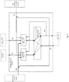
Figure 8 gives block diagram of SF AC A automation controller of subchannel A using the example ofchannel 1 SF AC A, where: 7 a is a segment of SF IOB A bus of subchannel A; 4 12, 4 13, 4 14 are interprocessor interfaces IPI A of subchannel A ofchannel 1 SF AC A communication with SF AC A ofchannels A automation processor 42 ofchannel 1 via buses IPI1 A, IPI2 A of subchannel A, respectively, with MCR and ECR; 15 1, 15 2, 15 3, 15 4 are lines of communication of BM-4A module 41 p-1, respectively, with IOS1, IOS2, IOS3, IOS4 stations ofchannel 1 via SF IOB A bus; 26 11, 26 12, 26 13, 26 14 are communication lines of BM-4 Amodule 41 2 with PCS A1-4 stations, respectively, ofchannels A modules 41 1-p. - I/O stations IOS1-n of each safety channel receive analog and binary signals of the process, convert them into digital form, and transmit via safety I/O buses SF IOB A 7 a of subchannel A and SF IOB
B 7b of subchannel B to automation controllers of the safety channel, respectively, SF AC A 2 a of subchannel A and SF ACB 2 b of subchannel B. Following commands of SF AC A 2a and SF AC B 2 b, stations IOS also generate and send control signals for CPS. - SF AC A 2 a and SF AC
B 2 b controllers convert received digital values of analog and binary signals into the process parameters, transmit them via interprocessor interfaces, respectively, IPI 4 a and IPI 4 b to automation controllers SF AC A 2 a and SF ACB 2 b of the other safety channels, receive process parameters from these safety channels, and execute software-based selection of parameters for further processing according to majority algorithm '2 out of 4' at the first level of interchannel communications and majority redundancy. Automation controllers SF AC A 2 a and SF AC B 2 b compare selected according to the majority algorithm process parameters with the predetermined limits of nuclear power plant safe operation. Further processing of the process parameters received is executed at several stages of implementation of protection algorithms, including intermediate conversion of the results of processing, interchannel communications viaIPI 4 a andIPI 4 b interfaces, and majority processing at every stage. - If SF AC A 2 a and SF AC B 2 b controllers detect an emergency situation as a result of analysis of input process parameters, they generate and send via SF IOB A 7 a and SF IOB A 7 b buses protective commands of AM control to the priority control stations PCS1-m 3 of their safety channel and to
PCS stations 3 of other safety channels at the second level of interchannel communications.
If emergency situation requires reactor trip, then SF AC A 2 a and SF AC B 2 b generate and send via I/O buses, respectively, SF IOB A 7 a and SF IOB A 7 b to respective IOS stations control commands for CPS. - Automation controllers SF AC A 2 a and SF AC B 2 b in the process of operation generate and send to the upper level of the normal operation system via redundant switched bus EN 5 of normal operation diagnostic information about execution of protection functions and the state of SF AC A 2 a and SF AC B 2 b, and IOS/PCS stations. Reception of information in SF AC A 2 a and SF AC B 2 b via EN bus from normal operation system is blocked.
Priority control stations PCS1-m 3 receive actuation mechanism control commands from SF AC A 2 a and SF AC B 2 b controllers of their own channel and of other safety channels via I/O buses SF IOB A 7 a and SF IOB A 7 b, and execute their hardware-based processing according to redundancy principle '2 out of 4' at the second level of interchannel communications.
PCS1-m stations 3, based on the commands selected according to majority algorithm '2 out of 4', generate control signals foractuation mechanisms AM 8 according to priorities of the control centers SF AC A 2 a and SF AC B 2 b. Control commands forAM 8 come to actuation mechanisms via gating circuits of PCS1-m looped following the commands from automation controllers SF AC A 2 a and SF AC B 2 b. Automation controllers read generated forAM 8 commands and output control signals forAM 8 via feedback links of priority control logic of PC S1-m stations and check whether prepared for sending toAM 8 and sent toAM 8 commands comply with the preset commands in order to exclude possibility of sending false control signals toactuation mechanisms AM 8 due to PCS faults.
Safety channel stations PCS1-m 3 also receive control commands from other control centers: the main control room MCR and emergency control room ECR, and generate control signals forAM 8 according to the priorities of the control centers. - MCR and ECR, according to
Figure 2 , are connected directly to PCS1-m stations 3 of each safety channel via wire lines, and to SF AC A 2 a and SF ACB 2 b controllers via bus communication lines IPI1 A 11 a1, IPI1B 11 b1 and IPI2A 11 a2, IPI2B 11 b2 built based on Ethernet 'point-to-point'-type interface and specific data-level communications protocol. - Via wire communication lines 101, 102, from MCR and ECR to
PCS 1-m 3 binary control signals are transmitted, and fromPCS 1-m 3 to MCR and ECR analog and binary signals reflecting state of priority control stations andAM 8 are transmitted to be displayed on safety panels. - Via communication lines IPI1
A 11 a1, IPI1B 11 b1 and IPI2A 11 a2, IPI2B 11 b2 from SF AC A 2 a and SF ACB 2 b controllers of safety channels to the MCR and ECR diagnostic information about execution of protection algorithms and extended diagnostic information about the state of actuation mechanisms and priority control modules is transmitted. - Stations IOS1-n 1 and PCS1-m 3 contain two independent sets of subchannel A and subchannel B software & hardware meeting diversity principle and implementing together with the two automation controllers SF AC A 2 a of subchannel A and SF AC
B 2 b of subchannel B separately all functions of the safety system channel. - In IOS station, which structure is shown in
Figure 3 using the example of IOS1 station ofchannel 1, subchannels A and B are implemented in the form of two communication modules: CICA 13 of SF IOB Abus 7a of subchannel A andCIC B 13 of SF IOBB bus 7b of subchannel B, and software & hardware of subchannels A and B integrated into MCP modules 12 1 - 12k. CIC A and CIC B modules are connected, respectively, via communication lines of SF IOB A 13 and SF IOBB 17 of 'point-to-point' type of serial duplex interface with each MCP module 12 1-12 k, and via communication lines of SF IOB A bus 15 1 and SF IOB B 18 1 of 'point-to-point' type - with automation controllers, respectively, SF AC A of subchannel A and SF AC B of subchannel B. - Communication modules CIC A 13 and CIC
B 16 distribute commands and data coming via lines 15 1 and 18 1 from SF AC A and SF AC B controllers, respectively, tocommunication lines lines - Modules of communication with the process MCP 12 1 - 12 k execute reception and reproduction of analog and binary signals of the process, conversion of input signals of the process into digital form and digital values of output signals into analog form, preprocessing of input signals, communication with SF AC A and SF AC B controllers via communication lines, respectively, 14, 15 1 and 17, 18 1 of buses SF IOB A 7 a and SF IOB B 7 b.
-
Figure 4 shows block diagram of analog signal input module MCP demonstrating arrangement of subchannels A and B hardware in MCP modules. Built-in hardware of subchannels is implemented in the module in the form of two processors SF CPU A 21 of subchannel A and SFCPU B 22 of subchannel B connected, respectively, via buses SF IOB A 14 and SF IOB B 17 with communication modules CIC A 13 and CIC B 16 (Figure 3 ), through which the access to theseprocessors Figure 3 ) for data exchange. - Process signal comes in the analog signal input module MCP via
input circuits 19 to the input of analog-to-digital converter ADC 20 that implements signal conversion into digital form. Processors SFCPU A 21 of subchannel A and SFCPU B 22 of subchannel B receive digital signal fromADC 20 output, execute its preprocessing and transmit it, respectively, via communication lines of SF IOB A 14 and SF IOB B 17 buses to communication modules CIC A 13 and CIC B 16 (Figures 3 and4 ). - Binary signal input modules and analog and binary signal output modules operate according to similar scheme (
Figure 4 ). - Arrangement of safety features of subchannels A and B of PCS station is represented using a variant of PCS station structure (
Figure 5 ) being part of a group of 4 stations PCS1-4, with which automation controller SF AC of each channel executes data exchange via one communication line of the SF IOB bus. Safety features of subchannels A and B of the PCS station are implemented in the form of: two communication modules of majority voting according to '2 out of 4'algorithm VM A 24 of subchannel A andVM B 28 of subchannel B, two communicationmodules VCM A 25 of subchannel A andVCM B 29 of subchannel B, and hardware & software of subchannels A and B integrated into PCM modules 23 1-23 e. Modules VM A and VM B are connected: via 'e' communication lines, respectively, 32 of SF IOB A 7 a and 33 of SF IOBB 7 b of 'point-to-point' type of serial duplex interface with each MCP module 23 1 -23 e ; viacommunication lines 27 of SF IOBA 7 a of subchannel A and 31 of SF IOBB 7 b of subchannel B - with communication modules VCM A and VCM B of the 3 other PCS stations. - Communication modules VM A 24 and VM
B 28 implement functions of branching of downstream commands and data, respectively, from SF AC A and SF AC B to PCM modules 23 1 - 23 e, and concentrating of upstream data from PCM modules 23 1 - 23 e to SF AC A and SF AC B, and also functions of hardware-based majority selection of downstream commands and data from 4 safety channels received viacommunication lines communication lines - Communication modules VCM
A 25 of subchannel A and VCMB 29 of subchannel B are connected, respectively: vialines 34 of SF IOB A and 35 of SF IOB B with VMA communication modules 24 andVM B 28 of their PCS station; viacommunication lines 27 of SF IOB A and 31 of SF IOB B - with communication modules VM A and VM B of the other 3 stations ofsafety channel 1; viacommunication lines own safety channel 1, and in the other 3 PCS stations - with SF AC A and SF AC B of the other 3 safety channels. -
Figure 6 shows structure of links via SF IOB A bus of subchannel A of a group of 4 stations PCS1-4 ofsafety channel 1 with SF AC A controller of this safety channel and with SF AC A controllers of the other 3 safety channels. VCM A module of PCS1 station viacommunication line 26 11 is connected with SF AC A controller of itschannel 1, VCM A module of PCS2 station viacommunication line 26 22 is connected with SF AC A controller ofchannel 2, VCM A module of PCS3 station viacommunication line 26 33 is connected with SF AC A controller ofchannel 3, VCM A module of PCS4 station viacommunication line 26 44 is connected with SF AC A controller ofchannel 4. VCM A module in each PCS1-4 station is connected with VM A modules of the other 3 PCS stations of the group: viacommunication lines communication lines communication lines communication lines - Via said links of SF IOB A bus the commands and data from SF AC A controller of each of the 4 channels come to VM A modules of each station of the group for execution of majority processing according to '2 out of 4' algorithm and for transmission of the selected commands and data via 'e' communication lines of
VM A modules 24 to PCM modules.
Arrangement of built-in hardware of subchannels A and B, and communications with the AM control centers in PCM modules is shown in block diagram of PCM module inFigure 7 .
PCM module executes control of AM following initiating commands from several control centers: from SF AC A controller of subchannel A via VM A modules and viacommunication line 32 of SF IOB A bus; from SF AC B controller of subchannel B viacommunication line 33 of SF IOB B bus (Figures 5 and7 ); from the MCR via wire lines 10 1 and from the ECR via wire lines 102. Transmission of PCM and AM state data is implemented via said links, respectively, to SF AC A, SF AC B, AC, MCR, and ECR. - Control commands for AM are generated: following initiating commands from SF AC A, MCR, and ECR in programmable logic circuit
SF PLC A 36 of subchannel A, and following initiating commands from SF AC B, MCR, and ECR in programmable logic circuitSF PLC B 37 of subchannel B. AM control commands fromSF PLC A 36 andSF PLC B 37 come to PLC of priority control logic -PCL PLC 38, where selection of command is executed according to the priorities of the control centers, and its transmission to the AM viacommunication line 40. Viafeedback line 40 from PCL PLC output and via SF IOB A and SF IOB B buses, SF AC A and SF AC B controllers (Figures 5 and7 ) inquire for the state of the command sent to AM and compare it with the preset command in order to control the command transmission channel from the controllers to the AM. Via input lines 39 and SF IOB A and SF IOB B buses SF AC A and SF AC B controllers read AM state signals. - Each safety channel contains 2 independent automation controllers: SF AC A of subchannel A and SF AC B of subchannel B.
Figure 8 shows block diagram of SF AC A of subchannel A ofsafety channel 1. SF AC B controller is built according to the same scheme. - Automation processor module
SF APM A 42 of SF AC A controller receives via SF IOB Abus 7 a digital values of the process parameters from MCP modules of IOS1-n stations of its safety channel, executes their processing, and in case of detecting emergency situation, in compliance with safety algorithms, generates and transmits via SF IOB Abus 7 a to PCM modules of PCS1-m stations of its own and other safety channels protective action control commands. In the process of execution of safety algorithms,SF APM A 42 implements data exchange with SF APM A ofsafety channels interprocessor interfaces IPI safety channel 1 with MCR - IPI1a A 11 a1 and with ECR - IPI2a A 11 a2, processor module receives remote control commands from the MCR and ECR and transmits to the MCR and ECR diagnostic information about execution of protection algorithms. Viaredundant bus EN APM A module 42 transmits diagnostic information of the safety system to the normal operation system. - Reception of data from IOS stations and PCS stations, and transmission of commands and data to PCS stations the processor module
SF APM A 42 executes: via lines of communication of I/O bus SF IOB A 43 1 - 43 p with communication modules BM-4 A 41 1 - 41 p, and further via lines of communication of BM-4 A modules with communicationmodules CIC A 13 of IOS stations (Figure 3 ) and communicationmodules VCM A 25 of PCS stations (Figure 5 ). Each communication module BM-4 A inFigure 8 can be linked via 4 branching lines with 4 IOS stations, for instance, with IOS1-4 of its own safety channel, or with 4 groups of 4 PCS stations, for instance, PCS1-4, of its own and 3 other safety channels.Figure 8 shows, as an example, connections of BM-4 41 p-1 of SFAPM A module 42 ofsafety channel 1 to 4 IOS1-4 stations of this channel, and connections of BM-4module 41 2 ofsafety channel 1 to groups of PCS1-4 stations of this channel and of the 3 other safety channels. - Communication module BM-4 41 p-1 is connected via communication line 151 to IOS1, via communication line 15 2 - to IOS2, via communication line 15 3 - to IOS3, and via communication line 15 4- to IOS4 of its own (1st) safety channel.
Communication module BM-4A 41 2 is connected viacommunication line 26 11 to 4 stations PCS1-4 of its own, i.e. 1st, safety channel, via communication line 26 12 - to 4 stations PCS1-4 ofsafety channel 2, via communication line 26 13 - to 4 stations PCS1-4 ofsafety channel 3, and via communication line 26 14 - to 4 stations PCS1-4 ofsafety channel 4.
Claims (4)
- A control safety system for use in nuclear plants, comprising:
a plurality of identical safety channels, each said channel includes process signal input/output stations IOS1-n, actuation mechanism priority control stations PCS1-m that are connected with the main control room MCR and emergency control room ECR, safety features automation controller SF AC, safety features input/output bus SF IOB for SF AC controller data exchange with IOS and PCS stations, and is cross-connected with other safety channels by means of duplex optical fiber communication paths, characterized in that the said IOS stations, priority control stations PCS and safety feature automation controller SF AC of each safety channel contain two mutually independent software & hardware sets forming subchannel A and subchannel B that are built based on different hardware & software platforms; each channel implements all functions of a safety channel; each channel of the control safety system includes SF AC A controller of subchannel A and SF AC B controller of subchannel B, each of which is connected, respectively, with SF AC A and SF AC B controllers of other safety channels via interprocessor interfaces IPI A and IPI B of 'point-to-point' type built based on Ethernet interface and data-level communications protocol with the normal operation system via redundant switched system bus EN of normal operation built based on Ethernet interface, ring structure of net switches connection and data-level communications protocol, with the main control room MCR and emergency control room ECR via bus communication lines IPI1 A, IPI1 B and IPI2 A, IPI2 B, respectively, built based on 'point-to-point'-type Ethernet interface and data-level communication protocol, with IOS1-n and PCS1-m stations of the safety channel and with PCS1-m stations of other safety channels via I/O bus, respectively, SF IOB A of subchannel A and SF IOB B of subchannel B, here each of SF IOB A and SF IOB B buses has a 'tree'-type structure, the upper root node of which is, respectively, automation processor module SF APM A of SF AC A controller and processor module SF APM B of SF AC B controller, and the low end nodes are modules of communication with the process MCP of IOS1-n stations and priority control modules PCM of PCS1-m stations, and intermediate nodes are communication modules, and links between SF IOB A nodes and between SF IOB B nodes are implemented here as the lines of serial duplex 'point-to-point'-type interface. - A control safety system for use in nuclear power plant according to claim 1, characterized in that the I/O station contains modules of communication with the process MCP1-k and two communication modules - converters of interfaces: CIC A of SF IOB A bus and CIC B of SF IOB B bus; here CIC A module, CIC B module are connected via one communication line of the module with its own automation controller SF AC A, SF AC B, and via separate communication lines with each MCP1-k module; modules of communication with the process MCP1-k of IOS station contain processor of subchannel A and processor of subchannel B that are connected, respectively, via intra-station lines of SF IOB A and SF IOB B buses with communication modules CIC A and CIC B, and via SF IOB A and SF IOB B buses are connected, respectively, to SF AC A controller of subchannel A and SF AC B controller of subchannel B.
- A control safety system for use in nuclear power plant according to claim 1, characterized in that each priority control station PCS contains priority control modules PCM1-e, communication modules of SF IOB A bus of subchannel A and SF IOB B bus of subchannel B: voting switch modules VCM A, VCM B and voting modules VM A, VM B of input commands from N safety channels according to '2 out of N' algorithm; in each safety channel the PCS stations are combined into groups of N stations, a number of PCS stations is determined by a number of safety channels, in subchannel A of each safety channel the first PCS1 station of the group is connected via FS IOB A communication line with SF AC A controller of its safety channel, the other stations PCS2-N of the group are connected with SF AC A controllers of the other N-1 safety channels, communication module VCM A of each PCS station is connected with voting communication module VM A of its own PCS station and with communication modules VM A of the other PCS stations of the group; communication module VM A of each PCS station is connected via SF IOB A communication lines with priority control modules PCM1-e, and in subchannel B of each safety channel the links of communication of PCM modules of PCS stations of the group with automation controllers SF AC B of each safety channel are implemented similarly to communication links of subchannel A; priority control modules PCM1-e of PCS station include safety feature programmable logic circuits - SF PLC A of subchannel A and SF PLC B of subchannel B that are connected, respectively, via intra-station lines of SF IOB A and SF IOB B buses with communication modules VM A of subchannel A and VM B of subchannel B and further via SF IOB A and SF IOB B buses are connected, respectively, to the controllers SF AC A of subchannel A and SF AC B of subchannel B.
- A control safety system for use in nuclear power plant according to claim 1, characterized in that the automation controller SF AC A of subchannel A of each safety channel contains automation processor module APM A and p communication modules BM-4 A of SF IOB A bus connected via SF IOB A communication lines with processor modules SF APM A, with communication modules CIC A of I/O stations IOS1-n and communication modules VCM A of priority control stations of their own safety channel and with communication modules VCM A of priority control stations PCS1-m of other safety channels; automation controller SF AC B of subchannel B of each safety channel is similar as to its configuration and links to that of subchannel A.
Applications Claiming Priority (2)
| Application Number | Priority Date | Filing Date | Title |
|---|---|---|---|
| RU2015125045/08A RU2582875C1 (en) | 2015-06-25 | 2015-06-25 | Control system for safety of nuclear power plant |
| PCT/RU2016/000355 WO2016209113A1 (en) | 2015-06-25 | 2016-06-10 | Safety control system for nuclear power plant |
Publications (3)
| Publication Number | Publication Date |
|---|---|
| EP3316260A1 true EP3316260A1 (en) | 2018-05-02 |
| EP3316260A4 EP3316260A4 (en) | 2019-03-27 |
| EP3316260B1 EP3316260B1 (en) | 2025-11-19 |
Family
ID=55794724
Family Applications (1)
| Application Number | Title | Priority Date | Filing Date |
|---|---|---|---|
| EP16814794.0A Active EP3316260B1 (en) | 2015-06-25 | 2016-06-10 | Safety control system for nuclear power plant |
Country Status (5)
| Country | Link |
|---|---|
| EP (1) | EP3316260B1 (en) |
| KR (1) | KR102278287B1 (en) |
| CN (1) | CN107924723B (en) |
| RU (1) | RU2582875C1 (en) |
| WO (1) | WO2016209113A1 (en) |
Cited By (2)
| Publication number | Priority date | Publication date | Assignee | Title |
|---|---|---|---|---|
| CN113784239A (en) * | 2021-09-07 | 2021-12-10 | 武汉华德环保工程技术有限公司 | Intelligent machine-side control device and control method |
| CN116066248A (en) * | 2022-10-11 | 2023-05-05 | 中国核动力研究设计院 | Nuclear power plant diesel generator set unloading instruction generation device and method |
Families Citing this family (2)
| Publication number | Priority date | Publication date | Assignee | Title |
|---|---|---|---|---|
| CN110361979B (en) * | 2019-07-19 | 2022-08-16 | 北京交大思诺科技股份有限公司 | Safety computer platform in railway signal field |
| CN111817900B (en) * | 2020-08-03 | 2022-07-01 | 苏州热工研究院有限公司 | Standby emergency command system of nuclear power plant and main-standby switching method |
Family Cites Families (13)
| Publication number | Priority date | Publication date | Assignee | Title |
|---|---|---|---|---|
| GB1272834A (en) * | 1968-06-24 | 1972-05-03 | Westinghouse Electric Corp | Control system |
| US5745539A (en) * | 1995-11-14 | 1998-04-28 | Westinghouse Electric Corporation | Apparatus and method for prioritization of multiple commands in an instrumentation and control system |
| US6049578A (en) * | 1997-06-06 | 2000-04-11 | Abb Combustion Engineering Nuclear Power, Inc. | Digital plant protection system |
| US5984504A (en) * | 1997-06-11 | 1999-11-16 | Westinghouse Electric Company Llc | Safety or protection system employing reflective memory and/or diverse processors and communications |
| RU2150756C1 (en) * | 1999-01-28 | 2000-06-10 | Грибов Алексей Алексеевич | Method for gathering and processing signals in nuclear reactor core monitoring system, and device for its embodiment |
| CN1119819C (en) * | 2000-11-10 | 2003-08-27 | 清华大学 | Digital reactor protecting system based on parallel hardware and software treatment |
| RU2260211C1 (en) * | 2004-09-03 | 2005-09-10 | Кудрявцев Михаил Юрьевич | System for vessel nuclear reactor control and two-position switch of the passive protection of a nuclear reactor (nr) |
| UA78477C2 (en) * | 2006-08-28 | 2007-03-15 | Yevhenii Stepanovych Bakhmach | Control digital safety system of nuclear station and method for providing the safety system parameters |
| US8117512B2 (en) * | 2008-02-06 | 2012-02-14 | Westinghouse Electric Company Llc | Failure detection and mitigation in logic circuits |
| US20110313580A1 (en) * | 2010-06-17 | 2011-12-22 | Levgenii Bakhmach | Method and platform to implement safety critical systems |
| RU2431174C1 (en) * | 2010-08-20 | 2011-10-10 | Федеральное государственное унитарное предприятие "Всероссийский научно-исследовательский институт автоматики им. Н.Л. Духова" (ФГУП "ВНИИА") | Backup software-hardware system for automatic monitoring and control |
| US20130315362A1 (en) * | 2012-05-25 | 2013-11-28 | Institute Of Nuclear Energy Research Atomic Energy Council, Executive Yuan | Nuclear digital instrumentation and control system |
| CN104332197A (en) * | 2013-07-22 | 2015-02-04 | 中国核动力研究设计院 | Double-channel redundant method for subgroup gating |
-
2015
- 2015-06-25 RU RU2015125045/08A patent/RU2582875C1/en active
-
2016
- 2016-06-10 CN CN201680038115.7A patent/CN107924723B/en active Active
- 2016-06-10 KR KR1020177037690A patent/KR102278287B1/en active Active
- 2016-06-10 WO PCT/RU2016/000355 patent/WO2016209113A1/en not_active Ceased
- 2016-06-10 EP EP16814794.0A patent/EP3316260B1/en active Active
Cited By (2)
| Publication number | Priority date | Publication date | Assignee | Title |
|---|---|---|---|---|
| CN113784239A (en) * | 2021-09-07 | 2021-12-10 | 武汉华德环保工程技术有限公司 | Intelligent machine-side control device and control method |
| CN116066248A (en) * | 2022-10-11 | 2023-05-05 | 中国核动力研究设计院 | Nuclear power plant diesel generator set unloading instruction generation device and method |
Also Published As
| Publication number | Publication date |
|---|---|
| KR102278287B1 (en) | 2021-07-20 |
| EP3316260A4 (en) | 2019-03-27 |
| KR20180032532A (en) | 2018-03-30 |
| CN107924723B (en) | 2021-01-22 |
| CN107924723A (en) | 2018-04-17 |
| WO2016209113A9 (en) | 2017-02-02 |
| WO2016209113A1 (en) | 2016-12-29 |
| EP3316260B1 (en) | 2025-11-19 |
| RU2582875C1 (en) | 2016-04-27 |
Similar Documents
| Publication | Publication Date | Title |
|---|---|---|
| EP3316262B1 (en) | Safety control system for a nuclear power plant | |
| EP3316261B1 (en) | Control system for the safety of nuclear power plant | |
| CN105575448B (en) | Nuclear power plant reactor protects system and method for controlling security therein | |
| CN110361979B (en) | Safety computer platform in railway signal field | |
| CN108287519B (en) | Logical construction and implementation method for proton therapy equipment safety interlocking | |
| EP3316260A1 (en) | Safety control system for nuclear power plant | |
| CN104409123A (en) | Priority management system of nuclear power plant | |
| CN106340332A (en) | Nuclear power station digital protection control system | |
| KR100848881B1 (en) | Digital reactor protection system | |
| US20130315362A1 (en) | Nuclear digital instrumentation and control system | |
| EP3576103B1 (en) | Nuclear power plant priority management system | |
| US6473479B1 (en) | Dual optical communication network for class 1E reactor protection systems | |
| KR102856884B1 (en) | Failure detection device applied to the dual control device for the electrical signal system of a nuclear power plant having and controlling method for the same | |
| KR101298459B1 (en) | Bus structure of fpga based controler | |
| CN116598032A (en) | Digital protection system of nuclear power plant based on FPGA | |
| US20190362620A1 (en) | Fire-prevention control unit | |
| Suh et al. | Developing architecture for upgrading I&C systems of an operating nuclear power plant using a quality attribute-driven design method | |
| Shimizu et al. | DCS Innovation by SIL and Non-SIL Unified Architecture-Hitachi Approach on G-HIACS (R800FS/R900) | |
| Kim et al. | Implementation of Multiloop Control for the Plant Control System in Improved Korean Standard Nuclear Power Plant (KSNP+) |
Legal Events
| Date | Code | Title | Description |
|---|---|---|---|
| STAA | Information on the status of an ep patent application or granted ep patent |
Free format text: STATUS: THE INTERNATIONAL PUBLICATION HAS BEEN MADE |
|
| PUAI | Public reference made under article 153(3) epc to a published international application that has entered the european phase |
Free format text: ORIGINAL CODE: 0009012 |
|
| STAA | Information on the status of an ep patent application or granted ep patent |
Free format text: STATUS: REQUEST FOR EXAMINATION WAS MADE |
|
| 17P | Request for examination filed |
Effective date: 20171227 |
|
| AK | Designated contracting states |
Kind code of ref document: A1 Designated state(s): AL AT BE BG CH CY CZ DE DK EE ES FI FR GB GR HR HU IE IS IT LI LT LU LV MC MK MT NL NO PL PT RO RS SE SI SK SM TR |
|
| AX | Request for extension of the european patent |
Extension state: BA ME |
|
| DAV | Request for validation of the european patent (deleted) | ||
| DAX | Request for extension of the european patent (deleted) | ||
| A4 | Supplementary search report drawn up and despatched |
Effective date: 20190221 |
|
| RIC1 | Information provided on ipc code assigned before grant |
Ipc: G05B 9/03 20060101ALI20190215BHEP Ipc: G21C 7/36 20060101AFI20190215BHEP |
|
| STAA | Information on the status of an ep patent application or granted ep patent |
Free format text: STATUS: EXAMINATION IS IN PROGRESS |
|
| 17Q | First examination report despatched |
Effective date: 20200717 |
|
| GRAP | Despatch of communication of intention to grant a patent |
Free format text: ORIGINAL CODE: EPIDOSNIGR1 |
|
| STAA | Information on the status of an ep patent application or granted ep patent |
Free format text: STATUS: GRANT OF PATENT IS INTENDED |
|
| INTG | Intention to grant announced |
Effective date: 20250623 |
|
| GRAS | Grant fee paid |
Free format text: ORIGINAL CODE: EPIDOSNIGR3 |
|
| GRAA | (expected) grant |
Free format text: ORIGINAL CODE: 0009210 |
|
| STAA | Information on the status of an ep patent application or granted ep patent |
Free format text: STATUS: THE PATENT HAS BEEN GRANTED |
|
| GRAT | Correction requested after decision to grant or after decision to maintain patent in amended form |
Free format text: ORIGINAL CODE: EPIDOSNCDEC |
|
| AK | Designated contracting states |
Kind code of ref document: B1 Designated state(s): AL AT BE BG CH CY CZ DE DK EE ES FI FR GB GR HR HU IE IS IT LI LT LU LV MC MK MT NL NO PL PT RO RS SE SI SK SM TR |
|
| REG | Reference to a national code |
Ref country code: CH Ref legal event code: F10 Free format text: ST27 STATUS EVENT CODE: U-0-0-F10-F00 (AS PROVIDED BY THE NATIONAL OFFICE) Effective date: 20251119 Ref country code: GB Ref legal event code: FG4D |
|
| REG | Reference to a national code |
Ref country code: DE Ref legal event code: R096 Ref document number: 602016094140 Country of ref document: DE |
|
| REG | Reference to a national code |
Ref country code: IE Ref legal event code: FG4D |
|
| REG | Reference to a national code |
Ref country code: NL Ref legal event code: MP Effective date: 20251119 |
|
| PG25 | Lapsed in a contracting state [announced via postgrant information from national office to epo] |
Ref country code: ES Free format text: LAPSE BECAUSE OF FAILURE TO SUBMIT A TRANSLATION OF THE DESCRIPTION OR TO PAY THE FEE WITHIN THE PRESCRIBED TIME-LIMIT Effective date: 20251119 |
|
| REG | Reference to a national code |
Ref country code: LT Ref legal event code: MG9D |
|
| PG25 | Lapsed in a contracting state [announced via postgrant information from national office to epo] |
Ref country code: NO Free format text: LAPSE BECAUSE OF FAILURE TO SUBMIT A TRANSLATION OF THE DESCRIPTION OR TO PAY THE FEE WITHIN THE PRESCRIBED TIME-LIMIT Effective date: 20260219 |
|
| PG25 | Lapsed in a contracting state [announced via postgrant information from national office to epo] |
Ref country code: FI Free format text: LAPSE BECAUSE OF FAILURE TO SUBMIT A TRANSLATION OF THE DESCRIPTION OR TO PAY THE FEE WITHIN THE PRESCRIBED TIME-LIMIT Effective date: 20251119 Ref country code: AT Free format text: LAPSE BECAUSE OF FAILURE TO SUBMIT A TRANSLATION OF THE DESCRIPTION OR TO PAY THE FEE WITHIN THE PRESCRIBED TIME-LIMIT Effective date: 20251119 Ref country code: HR Free format text: LAPSE BECAUSE OF FAILURE TO SUBMIT A TRANSLATION OF THE DESCRIPTION OR TO PAY THE FEE WITHIN THE PRESCRIBED TIME-LIMIT Effective date: 20251119 |
|
| REG | Reference to a national code |
Ref country code: AT Ref legal event code: MK05 Ref document number: 1859606 Country of ref document: AT Kind code of ref document: T Effective date: 20251119 |
|
| PG25 | Lapsed in a contracting state [announced via postgrant information from national office to epo] |
Ref country code: NL Free format text: LAPSE BECAUSE OF FAILURE TO SUBMIT A TRANSLATION OF THE DESCRIPTION OR TO PAY THE FEE WITHIN THE PRESCRIBED TIME-LIMIT Effective date: 20251119 |
|
| PG25 | Lapsed in a contracting state [announced via postgrant information from national office to epo] |
Ref country code: RS Free format text: LAPSE BECAUSE OF FAILURE TO SUBMIT A TRANSLATION OF THE DESCRIPTION OR TO PAY THE FEE WITHIN THE PRESCRIBED TIME-LIMIT Effective date: 20260219 |
|
| PG25 | Lapsed in a contracting state [announced via postgrant information from national office to epo] |
Ref country code: IS Free format text: LAPSE BECAUSE OF FAILURE TO SUBMIT A TRANSLATION OF THE DESCRIPTION OR TO PAY THE FEE WITHIN THE PRESCRIBED TIME-LIMIT Effective date: 20260319 |
|
| PG25 | Lapsed in a contracting state [announced via postgrant information from national office to epo] |
Ref country code: PT Free format text: LAPSE BECAUSE OF FAILURE TO SUBMIT A TRANSLATION OF THE DESCRIPTION OR TO PAY THE FEE WITHIN THE PRESCRIBED TIME-LIMIT Effective date: 20260319 |
|
| PG25 | Lapsed in a contracting state [announced via postgrant information from national office to epo] |
Ref country code: PL Free format text: LAPSE BECAUSE OF FAILURE TO SUBMIT A TRANSLATION OF THE DESCRIPTION OR TO PAY THE FEE WITHIN THE PRESCRIBED TIME-LIMIT Effective date: 20251119 |
|
| PG25 | Lapsed in a contracting state [announced via postgrant information from national office to epo] |
Ref country code: LV Free format text: LAPSE BECAUSE OF FAILURE TO SUBMIT A TRANSLATION OF THE DESCRIPTION OR TO PAY THE FEE WITHIN THE PRESCRIBED TIME-LIMIT Effective date: 20251119 |