EP3315981A1 - Method and system for relay diagnosis - Google Patents
Method and system for relay diagnosis Download PDFInfo
- Publication number
- EP3315981A1 EP3315981A1 EP17194614.8A EP17194614A EP3315981A1 EP 3315981 A1 EP3315981 A1 EP 3315981A1 EP 17194614 A EP17194614 A EP 17194614A EP 3315981 A1 EP3315981 A1 EP 3315981A1
- Authority
- EP
- European Patent Office
- Prior art keywords
- relay
- signal
- comparison result
- control signal
- determined
- Prior art date
- Legal status (The legal status is an assumption and is not a legal conclusion. Google has not performed a legal analysis and makes no representation as to the accuracy of the status listed.)
- Granted
Links
Images




Classifications
-
- G—PHYSICS
- G01—MEASURING; TESTING
- G01R—MEASURING ELECTRIC VARIABLES; MEASURING MAGNETIC VARIABLES
- G01R31/00—Arrangements for testing electric properties; Arrangements for locating electric faults; Arrangements for electrical testing characterised by what is being tested not provided for elsewhere
- G01R31/327—Testing of circuit interrupters, switches or circuit-breakers
- G01R31/3271—Testing of circuit interrupters, switches or circuit-breakers of high voltage or medium voltage devices
- G01R31/3272—Apparatus, systems or circuits therefor
-
- G—PHYSICS
- G01—MEASURING; TESTING
- G01R—MEASURING ELECTRIC VARIABLES; MEASURING MAGNETIC VARIABLES
- G01R31/00—Arrangements for testing electric properties; Arrangements for locating electric faults; Arrangements for electrical testing characterised by what is being tested not provided for elsewhere
- G01R31/327—Testing of circuit interrupters, switches or circuit-breakers
- G01R31/3277—Testing of circuit interrupters, switches or circuit-breakers of low voltage devices, e.g. domestic or industrial devices, such as motor protections, relays, rotation switches
- G01R31/3278—Testing of circuit interrupters, switches or circuit-breakers of low voltage devices, e.g. domestic or industrial devices, such as motor protections, relays, rotation switches of relays, solenoids or reed switches
-
- G—PHYSICS
- G01—MEASURING; TESTING
- G01R—MEASURING ELECTRIC VARIABLES; MEASURING MAGNETIC VARIABLES
- G01R31/00—Arrangements for testing electric properties; Arrangements for locating electric faults; Arrangements for electrical testing characterised by what is being tested not provided for elsewhere
- G01R31/28—Testing of electronic circuits, e.g. by signal tracer
- G01R31/2832—Specific tests of electronic circuits not provided for elsewhere
- G01R31/2836—Fault-finding or characterising
- G01R31/2839—Fault-finding or characterising using signal generators, power supplies or circuit analysers
- G01R31/2841—Signal generators
-
- G—PHYSICS
- G01—MEASURING; TESTING
- G01R—MEASURING ELECTRIC VARIABLES; MEASURING MAGNETIC VARIABLES
- G01R31/00—Arrangements for testing electric properties; Arrangements for locating electric faults; Arrangements for electrical testing characterised by what is being tested not provided for elsewhere
- G01R31/327—Testing of circuit interrupters, switches or circuit-breakers
-
- G—PHYSICS
- G01—MEASURING; TESTING
- G01R—MEASURING ELECTRIC VARIABLES; MEASURING MAGNETIC VARIABLES
- G01R31/00—Arrangements for testing electric properties; Arrangements for locating electric faults; Arrangements for electrical testing characterised by what is being tested not provided for elsewhere
- G01R31/50—Testing of electric apparatus, lines, cables or components for short-circuits, continuity, leakage current or incorrect line connections
- G01R31/54—Testing for continuity
Definitions
- the present application relates to the technical field of relay, and more particularly to a method and a system for relay diagnosis.
- a relay serves as an element in a battery management system for controlling open and close each branches.
- the fault will directly affect some functions to be unavailable to use.
- an adhesion fault occurs in the relay, the relay cannot be opened such that a series of serious problems, such as overcharge, over discharge, over-temperature, etc. will be likely to arise. Therefore, it is important to accurately diagnose if there is an open-circuit or adhesion fault occurs in a high-voltage relay.
- One of the disclosed methods for relay diagnosis is mainly used to detect the relay circuit.
- this method has such a drawback that in case of the occurrence of faults in the other devices, the method is unable to diagnose the relay.
- a purpose of the present application is to provide a method and a system for relay diagnosis capable of diagnosing the relay per se.
- the present application provides a method for relay diagnosis, including: transmitting a control signal to the relay, wherein types of the control signal include an enable signal and a disable signal; applying a detection signal at one side of the relay, and receiving a feedback signal at the other side of the relay; and comparing the detection signal with the feedback signal to obtain a comparison result, wherein if the comparison result matches the control signal, the relay is determined as being normal, otherwise, the relay is determined as fault.
- the relay if the comparison result matches the control signal, the relay is determined as being normal, otherwise, the relay is determined as fault, which particularly includes: if the comparison result is inconsistency and the control signal is the disable signal, then the comparison result matches the control signal and the relay is determined as being normal; if the comparison result is consistence and the control signal is the enable signal, then the comparison result matches the control signal and the relay is determined as being normal; if the comparison result is inconsistency and the control signal is the enable signal, then the comparison result does not match the control signal and the relay is determined as fault; and if the comparison result is consistence and the control signal is the disable signal, then the comparison result does not match the control signal and the relay is determined as fault.
- the comparison result is inconsistency and the control signal is the enable signal
- the comparison result does not match the control signal and the relay is determined as fault
- the comparison result is inconsistency and the control signal is the enable signal
- the comparison result does not match the control signal and the relay is determined as open-circuit fault
- the comparison result is consistence and the control signal is the disable signal
- the comparison result does not match the control signal and the relay is determined as fault, which particularly includes: if the comparison result is consistence and the control signal is the disable signal, then the comparison result does not match the control signal and the relay is determined as adhesion fault.
- the detection signal is applied on the inside or outside of the relay.
- the detection signal is applied by a signal generator-receiver in parallel with the relay, and the feedback signal is received by the signal generator-receiver.
- the detection signal is applied by a signal generator connected to one side of the relay, and the feedback signal is received by a signal receiver connected to the other side of the relay.
- the present application provides a system for relay diagnosis, including: a control signal transmitting module configured to transmit a control signal to the relay, wherein types of the control signal include an enable signal and a disable signal; a detection-feedback signal module configured to apply a detection signal at one side of the relay, and receive a feedback signal at the other side of the relay; and a diagnosis module configured to compare the detection signal with the feedback signal to obtain a comparison result, wherein if the comparison result matches the control signal, the relay is determined as being normal, otherwise, the relay is determined as fault.
- a control signal transmitting module configured to transmit a control signal to the relay, wherein types of the control signal include an enable signal and a disable signal
- a detection-feedback signal module configured to apply a detection signal at one side of the relay, and receive a feedback signal at the other side of the relay
- a diagnosis module configured to compare the detection signal with the feedback signal to obtain a comparison result, wherein if the comparison result matches the control signal, the relay is determined as being normal, otherwise, the
- the relay if the comparison result matches the control signal, the relay is determined as being normal, otherwise, the relay is determined as fault, which particularly includes: if the comparison result is inconsistency and the control signal is the disable signal, then the comparison result matches the control signal and the relay is determined as being normal; if the comparison result is consistence and the control signal is the enable signal, then the comparison result matches the control signal and the relay is determined as being normal; if the comparison result is inconsistency and the control signal is the enable signal, then the comparison result does not match the control signal and the relay is determined as fault; and if the comparison result is consistence and the control signal is the disable signal, then the comparison result does not match the control signal and the relay is determined as fault.
- the comparison result is inconsistency and the control signal is the enable signal
- the comparison result does not match the control signal and the relay is determined as fault
- the comparison result is inconsistency and the control signal is the enable signal
- the comparison result does not match the control signal and the relay is determined as open-circuit fault
- the comparison result is consistence and the control signal is the disable signal
- the comparison result does not match the control signal and the relay is determined as fault, which particularly includes: if the comparison result is consistence and the control signal is the disable signal, then the comparison result does not match the control signal and the relay is determined as adhesion fault.
- the detection signal is applied on the inside or outside of the relay.
- the detection-feedback signal module is a signal generator-receiver in parallel with the relay.
- the detection-feedback signal module includes a signal generator connected to one side of the relay and a signal receiver connected to the other side of the relay, wherein the signal generator is configured to apply the detection signal at one side of the relay and the signal receiver is configured to receive feedback signal at the other side of the relay.
- the method and system for relay diagnosis provided in the present application simply needs to concern whether the relay being diagnosed is enabled or not, and compares the received feedback signal with the applied detection signal so as to realize the relay diagnosis.
- the diagnostic efficiency and accuracy can be improved.
- FIG. 1 illustrates a flow chart of the method for relay diagnosis provided in the present application, including the following steps.
- step S101 transmitting a control signal to the relay, types of the control signal include an enable signal and a disable signal.
- step S102 applying a detection signal at one side of the relay, and receiving a feedback signal at the other side of the relay.
- step S103 comparing the detection signal with the feedback signal to obtain a comparison result. If the comparison result matches the control signal, the relay is determined as being normal; otherwise, the relay is determined as fault.
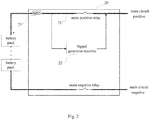
- the battery management system may perform the step S101 to transmit the control signal to control the opening and closing of the relay 21.
- the relay 21 is a main positive relay provided in a high voltage box 20, which is disposed behind a MSD (Manual Service disconnect) 23 and used to control the opening and closing of each branches.
- a signal generator-receiver 22 applies the detection signal at one side of the relay 21, and receives the feedback signal at the other side of the relay 21.
- the present application is not limited by the type of the relay being diagnosed, which can be a main positive relay, a main negative relay, a charging positive relay, a charging negative relay, a heating relay or any other relay which employs the present application.
- the battery management system transmits the disable signal to open the relay 21, and controls the signal generator-receiver 22 to apply the detection signal, receive the feedback signal from the other side of the relay 21, and compare the received feedback signal with the applied detection signal, then the battery management system can determine if the adhesion fault occurs in the relay.
- the battery management system transmits the enable signal to close the relay 21, and controls the signal generator-receiver 22 to apply the detection signal and compare the received feedback signal with the detection signal, then the battery management system can determine if the open-circuit fault occurs in the relay.
- the present application employs the battery management system to control the enable state of the relay and the signal generator-receiver to apply the detection signal, and then compare the received feedback signal with the detection signal so as to realize the purpose of diagnosing the adhesion or open-circuit fault for the relay.
- the relay if the comparison result matches the control signal, the relay is determined as being normal, otherwise, the relay is determined as fault, which particularly includes: if the comparison result is inconsistency and the control signal is the disable signal, then the comparison result matches the control signal and the relay is determined as being normal; if the comparison result is consistence and the control signal is the enable signal, then the comparison result matches the control signal and the relay is determined as being normal; if the comparison result is inconsistency and the control signal is the enable signal, then the comparison result does not match the control signal and the relay is determined as fault; and if the comparison result is consistence and the control signal is the disable signal, then the comparison result does not match the control signal and the relay is determined as fault.
- Fig. 3 is a comparison chart for the applied detection signal and the received feedback signal. It should be noted that the present application does not limit the waveform of the detection signal, which may be a square wave, a pulse, a high level or even any waveform.
- the battery management system transmits the disable signal to open the relay and controls the signal generator-receiver to apply the detection signal 31 as shown in Fig. 3 , if the received feedback signal is as the feedback signal 32 shown in Fig. 3 , the relay can be determined as fault; and if the received feedback is as the feedback signal 33 shown in Fig. 3 , the relay can be determined as being normal.
- the battery management system transmits the enable signal to close the relay and controls the signal generator-receiver to apply the detection signal 31 as shown in Fig. 3
- the relay can be determined as being normal; and if the received feedback is as the feedback signal 33 shown in Fig. 3 , the relay may be determined as fault.
- the form of the feedback signal used to determine whether there is a fault occurs in the relay is not limit to the form shown in Fig. 3 , instead the form is determined based on the detection signal and the coupled manner. The present application does not limit in this respect.
- the comparison result is inconsistency and the control signal is the enable signal
- the comparison result does not match the control signal and the relay is determined as fault
- the comparison result is inconsistency and the control signal is the enable signal
- the comparison result does not match the control signal and the relay is determined as open-circuit fault
- the comparison result is consistence and the control signal is the disable signal
- the comparison result does not match the control signal and the relay is determined as fault, which particularly includes: if the comparison result is consistence and the control signal is the disable signal, then the comparison result does not match the control signal and the relay is determined as adhesion fault.
- the battery management system transmits the disable signal to open the relay, and controls the signal generator-receiver to apply the detection signal 31 as shown in Fig. 3 .
- the relay is determined as adhesion fault
- the battery management system transmits the enable signal to close the relay, and controls the signal generator-receiver to apply the detection signal 31 as shown in Fig. 3 .
- the relay is determined as without open-circuit fault; and if the received feedback signal is as the feedback signal 33 shown in Fig. 3 , the relay is determined as open-circuit fault-free.
- the form of the feedback signal used to determine whether there is an adhesion or open-circuit fault occurs in the relay is not limit to the form shown in Fig. 3 , instead the form is determined based on the detection signal and the coupled manner. The present application does not limit in this respect.
- the detection signal is applied on the inside or outside of the relay.
- the detection signal may be applied, by the signal generator-receivers 41 and 45, on the outside of the main positive relay 43 and the charging negative relay 47 within the high voltage box 40, and the feedback signal is received from the inside of the main positive relay 43 and the charging negative relay 47.
- the detection signal may be applied, by the signal generator-receivers 42 and 46, on the inside of the charging positive relay 44 and the main negative relay 48, and the feedback signal is received from the outside of the charging positive relay 44 and the main negative relay 48.
- the detection signal is applied by a signal generator-receiver in parallel with the relay, and the feedback signal is received by the signal generator-receiver.
- the detection signal is applied by a signal generator connected to one side of the relay, and the feedback signal is received by a signal receiver connected to the other side of the relay.
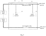
- a signal generator 51 applies the detection signal, while a signal receiver 52 receives the feedback signal and diagnoses the relay 53.
- the relay 53 is indicated to the main positive relay disposed behind a MSD 54 within the high voltage box 50.
- Fig. 6 is a system module diagram of the system for relay diagnosis provided in the present application.
- the system includes: a control signal transmitting module 601 configured to transmit the control signal to the relay 604, wherein types of the control signal include the enable signal and the disable signal; a detection-feedback signal module 602 configured to apply the detection signal at one side of the relay 604 and receive a feedback signal at the other side of the relay 604; and a diagnosis module 603 configured to compare the detection signal with the feedback signal to obtain a comparison result, wherein if the comparison result matches the control signal, the relay is determined as being normal, otherwise, the relay is determined as fault.
- a control signal transmitting module 601 configured to transmit the control signal to the relay 604, wherein types of the control signal include the enable signal and the disable signal
- a detection-feedback signal module 602 configured to apply the detection signal at one side of the relay 604 and receive a feedback signal at the other side of the relay 604
- a diagnosis module 603 configured to compare the detection signal with the feedback signal to
- the battery management system 605 may inform the control signal transmitting module 601 to transmit the control signal, and the diagnosis module 603 returns the comparison result to the battery management system 605.
- the relay if the comparison result matches the control signal, the relay is determined as being normal, otherwise, the relay is determined as fault, which particularly includes: if the comparison result is inconsistency and the control signal is the disable signal, then the comparison result matches the control signal and the relay is determined as being normal; if the comparison result is consistence and the control signal is the enable signal, then the comparison result matches the control signal and the relay is determined as being normal; if the comparison result is inconsistency and the control signal is the enable signal, then the comparison result does not match the control signal and the relay is determined as fault; and if the comparison result is consistence and the control signal is the disable signal, then the comparison result does not match the control signal and the relay is determined as fault.
- the comparison result is inconsistency and the control signal is the enable signal
- the comparison result does not match the control signal and the relay is determined as fault
- the comparison result is inconsistency and the control signal is the enable signal
- the comparison result does not match the control signal and the relay is determined as open-circuit fault
- the comparison result is consistence and the control signal is the disable signal
- the comparison result does not match the control signal and the relay is determined as fault, which particularly includes: if the comparison result is consistence and the control signal is the disable signal, then the comparison result does not match the control signal and the relay is determined as adhesion fault.
- the detection signal is applied on the inside or outside of the relay.
- the detection-feedback signal module is a signal generator-receiver in parallel with the relay.
- the detection-feedback signal module includes a signal generator connected to one side of the relay and a signal receiver connected to the other side of the relay, wherein the signal generator is configured to apply the detection signal at one side of the relay, and the signal receiver is configured to receive feedback signal at the other side of the relay.
- the method and system for relay diagnosis provided in the present application can realize the relay diagnosis by transmitting the control signal to the relay being diagnosed and comparing the received feedback signal with the applied detection signal.
- the method and system for relay diagnosis provided in the present application can at least avoid the impacts from other devices in the relay circuit during the process of diagnosis, and thus improving the diagnostic efficiency and accuracy.
Landscapes
- Physics & Mathematics (AREA)
- General Physics & Mathematics (AREA)
- Engineering & Computer Science (AREA)
- General Engineering & Computer Science (AREA)
- Remote Monitoring And Control Of Power-Distribution Networks (AREA)
- Emergency Protection Circuit Devices (AREA)
- Monitoring And Testing Of Transmission In General (AREA)
Abstract
Description
- The present application relates to the technical field of relay, and more particularly to a method and a system for relay diagnosis.
- In today's world, the energy crisis has received a growing concern from people all over the world. Conventional automobiles rely on non-renewable energy, such as gasoline, diesel and so on. At present, reserves of this kind of energy on earth have continuously decreased. More and more wars break out due to the energy crisis. The emergence of new energy automobile can effectively alleviate the energy crisis and achieve the sustainable development. Moreover, the environmental pollution has become an increasingly serious problem. The combustion of gasoline or diesel produces a large quantity of sulfide or particulate matter. These products will seriously pollute the atmosphere, and even worse, when encountering rain, the sulfide is easy to form acid rain, which will bring other pollution problems. As series of problems arise, there is an urgent demand on new energy industry and new energy automobile. At the same time, in order to vigorously promote the development of new energy automobiles, the government has introduced a series of high subsidy policies. These policies have played a positive role in the development of new energy automobiles, but also put forward higher and higher requirements on the new energy automobile technology. Especially the safety performance of the new energy automobile has always been the focus of people's attention. A relay serves as an element in a battery management system for controlling open and close each branches. When an open-circuit fault occurs in the relay, the fault will directly affect some functions to be unavailable to use. When an adhesion fault occurs in the relay, the relay cannot be opened such that a series of serious problems, such as overcharge, over discharge, over-temperature, etc. will be likely to arise. Therefore, it is important to accurately diagnose if there is an open-circuit or adhesion fault occurs in a high-voltage relay.
- One of the disclosed methods for relay diagnosis is mainly used to detect the relay circuit. However, considering the relay circuit per se has other devices, this method has such a drawback that in case of the occurrence of faults in the other devices, the method is unable to diagnose the relay.
- A purpose of the present application is to provide a method and a system for relay diagnosis capable of diagnosing the relay per se.
- In order to achieve the purpose noted above, the present application provides a method for relay diagnosis, including: transmitting a control signal to the relay, wherein types of the control signal include an enable signal and a disable signal; applying a detection signal at one side of the relay, and receiving a feedback signal at the other side of the relay; and comparing the detection signal with the feedback signal to obtain a comparison result, wherein if the comparison result matches the control signal, the relay is determined as being normal, otherwise, the relay is determined as fault.
- In some embodiments, if the comparison result matches the control signal, the relay is determined as being normal, otherwise, the relay is determined as fault, which particularly includes: if the comparison result is inconsistency and the control signal is the disable signal, then the comparison result matches the control signal and the relay is determined as being normal; if the comparison result is consistence and the control signal is the enable signal, then the comparison result matches the control signal and the relay is determined as being normal; if the comparison result is inconsistency and the control signal is the enable signal, then the comparison result does not match the control signal and the relay is determined as fault; and if the comparison result is consistence and the control signal is the disable signal, then the comparison result does not match the control signal and the relay is determined as fault.
- In some embodiments, if the comparison result is inconsistency and the control signal is the enable signal, then the comparison result does not match the control signal and the relay is determined as fault, which particularly includes: if the comparison result is inconsistency and the control signal is the enable signal, then the comparison result does not match the control signal and the relay is determined as open-circuit fault; and if the comparison result is consistence and the control signal is the disable signal, then the comparison result does not match the control signal and the relay is determined as fault, which particularly includes: if the comparison result is consistence and the control signal is the disable signal, then the comparison result does not match the control signal and the relay is determined as adhesion fault.
- In some embodiments, the detection signal is applied on the inside or outside of the relay.
- In some embodiments, the detection signal is applied by a signal generator-receiver in parallel with the relay, and the feedback signal is received by the signal generator-receiver.
- In some embodiments, the detection signal is applied by a signal generator connected to one side of the relay, and the feedback signal is received by a signal receiver connected to the other side of the relay.
- In order to achieve the purpose noted above, the present application provides a system for relay diagnosis, including: a control signal transmitting module configured to transmit a control signal to the relay, wherein types of the control signal include an enable signal and a disable signal; a detection-feedback signal module configured to apply a detection signal at one side of the relay, and receive a feedback signal at the other side of the relay; and a diagnosis module configured to compare the detection signal with the feedback signal to obtain a comparison result, wherein if the comparison result matches the control signal, the relay is determined as being normal, otherwise, the relay is determined as fault.
- In some embodiments, if the comparison result matches the control signal, the relay is determined as being normal, otherwise, the relay is determined as fault, which particularly includes: if the comparison result is inconsistency and the control signal is the disable signal, then the comparison result matches the control signal and the relay is determined as being normal; if the comparison result is consistence and the control signal is the enable signal, then the comparison result matches the control signal and the relay is determined as being normal; if the comparison result is inconsistency and the control signal is the enable signal, then the comparison result does not match the control signal and the relay is determined as fault; and if the comparison result is consistence and the control signal is the disable signal, then the comparison result does not match the control signal and the relay is determined as fault.
- In some embodiments, if the comparison result is inconsistency and the control signal is the enable signal, then the comparison result does not match the control signal and the relay is determined as fault, which particularly includes: if the comparison result is inconsistency and the control signal is the enable signal, then the comparison result does not match the control signal and the relay is determined as open-circuit fault; and if the comparison result is consistence and the control signal is the disable signal, then the comparison result does not match the control signal and the relay is determined as fault, which particularly includes: if the comparison result is consistence and the control signal is the disable signal, then the comparison result does not match the control signal and the relay is determined as adhesion fault.
- In some embodiments, the detection signal is applied on the inside or outside of the relay.
- In some embodiments, the detection-feedback signal module is a signal generator-receiver in parallel with the relay.
- In some embodiments, the detection-feedback signal module includes a signal generator connected to one side of the relay and a signal receiver connected to the other side of the relay, wherein the signal generator is configured to apply the detection signal at one side of the relay and the signal receiver is configured to receive feedback signal at the other side of the relay.
- The method and system for relay diagnosis provided in the present application simply needs to concern whether the relay being diagnosed is enabled or not, and compares the received feedback signal with the applied detection signal so as to realize the relay diagnosis. Thus, the diagnostic efficiency and accuracy can be improved.
- The method and system for relay diagnosis provided in the present application and the advantages thereof will be further described in detail below by way of specific embodiments and in conjunction with the accompanying drawings.
-
Fig. 1 is a flow chart of the method for relay diagnosis provided in the present application; -
Fig. 2 is a circuit diagram of an embodiment of the method for relay diagnosis provided in the present application; -
Fig. 3 is a comparison chart for the applied detection signal and the received feedback signal; -
Fig. 4 is a circuit diagram of another embodiment of the method for relay diagnosis provided in the present application; -
Fig. 5 is a circuit diagram of yet another embodiment of the method for relay diagnosis provided in the present application; -
Fig. 6 is a system module diagram of the system for relay diagnosis provided in the present application. - To clarify the purpose, technical solutions and advantages, the present application is described in detail below in conjunction with drawings and specific embodiments. It should be noted that the specific embodiments described in the specification are merely provided for explanation, and not for limitation.
- Referring to
Fig. 1 , which illustrates a flow chart of the method for relay diagnosis provided in the present application, including the following steps. - In step S101, transmitting a control signal to the relay, types of the control signal include an enable signal and a disable signal.
- In step S102, applying a detection signal at one side of the relay, and receiving a feedback signal at the other side of the relay.
- In step S103, comparing the detection signal with the feedback signal to obtain a comparison result. If the comparison result matches the control signal, the relay is determined as being normal; otherwise, the relay is determined as fault.
- Reference is made to
Fig. 2 . In an embodiment of the method for relay diagnosis provided in the present application, the battery management system may perform the step S101 to transmit the control signal to control the opening and closing of therelay 21. In the embodiment, therelay 21 is a main positive relay provided in ahigh voltage box 20, which is disposed behind a MSD (Manual Service disconnect) 23 and used to control the opening and closing of each branches. A signal generator-receiver 22 applies the detection signal at one side of therelay 21, and receives the feedback signal at the other side of therelay 21. It should be noted that the present application is not limited by the type of the relay being diagnosed, which can be a main positive relay, a main negative relay, a charging positive relay, a charging negative relay, a heating relay or any other relay which employs the present application. In case of employing the battery management system, when the relay is required to be diagnosed if the adhesion fault occurs therein, the battery management system transmits the disable signal to open therelay 21, and controls the signal generator-receiver 22 to apply the detection signal, receive the feedback signal from the other side of therelay 21, and compare the received feedback signal with the applied detection signal, then the battery management system can determine if the adhesion fault occurs in the relay. When therelay 21 is required to be determined if the open-circuit fault occurs therein, the battery management system transmits the enable signal to close therelay 21, and controls the signal generator-receiver 22 to apply the detection signal and compare the received feedback signal with the detection signal, then the battery management system can determine if the open-circuit fault occurs in the relay. To sum up, the present application employs the battery management system to control the enable state of the relay and the signal generator-receiver to apply the detection signal, and then compare the received feedback signal with the detection signal so as to realize the purpose of diagnosing the adhesion or open-circuit fault for the relay. - In an embodiment of the method for relay diagnosis provided in the present application, if the comparison result matches the control signal, the relay is determined as being normal, otherwise, the relay is determined as fault, which particularly includes: if the comparison result is inconsistency and the control signal is the disable signal, then the comparison result matches the control signal and the relay is determined as being normal; if the comparison result is consistence and the control signal is the enable signal, then the comparison result matches the control signal and the relay is determined as being normal; if the comparison result is inconsistency and the control signal is the enable signal, then the comparison result does not match the control signal and the relay is determined as fault; and if the comparison result is consistence and the control signal is the disable signal, then the comparison result does not match the control signal and the relay is determined as fault.
- Reference is made to
Fig. 3 , which is a comparison chart for the applied detection signal and the received feedback signal. It should be noted that the present application does not limit the waveform of the detection signal, which may be a square wave, a pulse, a high level or even any waveform. When the battery management system transmits the disable signal to open the relay and controls the signal generator-receiver to apply thedetection signal 31 as shown inFig. 3 , if the received feedback signal is as thefeedback signal 32 shown inFig. 3 , the relay can be determined as fault; and if the received feedback is as thefeedback signal 33 shown inFig. 3 , the relay can be determined as being normal. Similarly, when the battery management system transmits the enable signal to close the relay and controls the signal generator-receiver to apply thedetection signal 31 as shown inFig. 3 , if the received feedback signal is as thefeedback signal 32 shown inFig. 3 , the relay can be determined as being normal; and if the received feedback is as thefeedback signal 33 shown inFig. 3 , the relay may be determined as fault. The form of the feedback signal used to determine whether there is a fault occurs in the relay is not limit to the form shown inFig. 3 , instead the form is determined based on the detection signal and the coupled manner. The present application does not limit in this respect. - In an embodiment of the method for relay diagnosis provided in the present invention, if the comparison result is inconsistency and the control signal is the enable signal, then the comparison result does not match the control signal and the relay is determined as fault, which particularly includes: if the comparison result is inconsistency and the control signal is the enable signal, then the comparison result does not match the control signal and the relay is determined as open-circuit fault; and if the comparison result is consistence and the control signal is the disable signal, then the comparison result does not match the control signal and the relay is determined as fault, which particularly includes: if the comparison result is consistence and the control signal is the disable signal, then the comparison result does not match the control signal and the relay is determined as adhesion fault.
- Still referring to
Fig. 3 , when the relay is determined as adhesion fault, the battery management system transmits the disable signal to open the relay, and controls the signal generator-receiver to apply thedetection signal 31 as shown inFig. 3 . In this case, if the received feedback signal is as thefeedback signal 32 shown inFig. 3 , the relay is determined as adhesion fault; and if the received feedback signal is as thefeedback signal 33 shown inFig. 3 , the relay is determined as adhesion fault-free. Similarly, when the relay is determined as open-circuit fault, the battery management system transmits the enable signal to close the relay, and controls the signal generator-receiver to apply thedetection signal 31 as shown inFig. 3 . In this case, if the received feedback signal is as thefeedback signal 32 shown inFig. 3 , the relay is determined as without open-circuit fault; and if the received feedback signal is as thefeedback signal 33 shown inFig. 3 , the relay is determined as open-circuit fault-free. The form of the feedback signal used to determine whether there is an adhesion or open-circuit fault occurs in the relay is not limit to the form shown inFig. 3 , instead the form is determined based on the detection signal and the coupled manner. The present application does not limit in this respect. - In an embodiment of the method for relay diagnosis provided in the present application, the detection signal is applied on the inside or outside of the relay.
- Reference is made to
Fig. 4 , in particular, the detection signal may be applied, by the signal generator-receivers positive relay 43 and the chargingnegative relay 47 within thehigh voltage box 40, and the feedback signal is received from the inside of the mainpositive relay 43 and the chargingnegative relay 47. Alternatively, the detection signal may be applied, by the signal generator-receivers positive relay 44 and the mainnegative relay 48, and the feedback signal is received from the outside of the chargingpositive relay 44 and the mainnegative relay 48. - In an embodiment of the method for relay diagnosis provided in the present application, the detection signal is applied by a signal generator-receiver in parallel with the relay, and the feedback signal is received by the signal generator-receiver.
- In an embodiment of the method for relay diagnosis provided in the present application, the detection signal is applied by a signal generator connected to one side of the relay, and the feedback signal is received by a signal receiver connected to the other side of the relay.
- Reference is made to
Fig. 5 , asignal generator 51 applies the detection signal, while asignal receiver 52 receives the feedback signal and diagnoses therelay 53. In this case, therelay 53 is indicated to the main positive relay disposed behind aMSD 54 within thehigh voltage box 50. - Reference is made to
Fig. 6 , which is a system module diagram of the system for relay diagnosis provided in the present application. The system includes: a controlsignal transmitting module 601 configured to transmit the control signal to therelay 604, wherein types of the control signal include the enable signal and the disable signal; a detection-feedback signal module 602 configured to apply the detection signal at one side of therelay 604 and receive a feedback signal at the other side of therelay 604; and adiagnosis module 603 configured to compare the detection signal with the feedback signal to obtain a comparison result, wherein if the comparison result matches the control signal, the relay is determined as being normal, otherwise, the relay is determined as fault. - In particular, the battery management system 605 may inform the control
signal transmitting module 601 to transmit the control signal, and thediagnosis module 603 returns the comparison result to the battery management system 605. - In an embodiment of the system for relay diagnosis provided in the present application, if the comparison result matches the control signal, the relay is determined as being normal, otherwise, the relay is determined as fault, which particularly includes: if the comparison result is inconsistency and the control signal is the disable signal, then the comparison result matches the control signal and the relay is determined as being normal; if the comparison result is consistence and the control signal is the enable signal, then the comparison result matches the control signal and the relay is determined as being normal; if the comparison result is inconsistency and the control signal is the enable signal, then the comparison result does not match the control signal and the relay is determined as fault; and if the comparison result is consistence and the control signal is the disable signal, then the comparison result does not match the control signal and the relay is determined as fault.
- In an embodiment of the system for relay diagnosis provided in the present application, if the comparison result is inconsistency and the control signal is the enable signal, then the comparison result does not match the control signal and the relay is determined as fault, which particularly includes: if the comparison result is inconsistency and the control signal is the enable signal, then the comparison result does not match the control signal and the relay is determined as open-circuit fault; and if the comparison result is consistence and the control signal is the disable signal, then the comparison result does not match the control signal and the relay is determined as fault, which particularly includes: if the comparison result is consistence and the control signal is the disable signal, then the comparison result does not match the control signal and the relay is determined as adhesion fault.
- In an embodiment of the system for relay diagnosis provided in the present application, the detection signal is applied on the inside or outside of the relay.
- In an embodiment of the system for relay diagnosis provided in the present application, the detection-feedback signal module is a signal generator-receiver in parallel with the relay.
- In an embodiment of the system for relay diagnosis provided in the present application, the detection-feedback signal module includes a signal generator connected to one side of the relay and a signal receiver connected to the other side of the relay, wherein the signal generator is configured to apply the detection signal at one side of the relay, and the signal receiver is configured to receive feedback signal at the other side of the relay.
- To sum up, the method and system for relay diagnosis provided in the present application can realize the relay diagnosis by transmitting the control signal to the relay being diagnosed and comparing the received feedback signal with the applied detection signal.
- The method and system for relay diagnosis provided in the present application can at least avoid the impacts from other devices in the relay circuit during the process of diagnosis, and thus improving the diagnostic efficiency and accuracy.
- Various changes and modifications may be made by those skilled in the art, according to the disclosure and teaching of the foregoing descriptions. Thus, the specific implementations disclosed and described above are not intended to limit the present application. Any modifications and changes made to the present application are intended to be included within the claimed scope thereof. Although some specific terminologies are used in this specification, these terminologies are merely for convenience of illustration and are not intended to limit the present application.
Claims (12)
- A method for relay diagnosis characterized by comprising:transmitting (S101) a control signal to the relay, wherein types of the control signal comprise an enable signal and a disable signal;applying (S102) a detection signal at one side of the relay, and receiving a feedback signal at the other side of the relay; andcomparing (S103) the detection signal with the feedback signal to obtain a comparison result, wherein if the comparison result matches the control signal, the relay is determined as being normal, otherwise, the relay is determined as fault.
- The method for relay diagnosis of claim 1, wherein if the comparison result matches the control signal, the relay is determined as being normal, otherwise, the relay is determined as fault, particularly comprises:if the comparison result is inconsistency and the control signal is the disable signal, then the comparison result matches the control signal and the relay is determined as being normal;if the comparison result is consistence and the control signal is the enable signal, then the comparison result matches the control signal and the relay is determined as being normal;if the comparison result is inconsistency and the control signal is the enable signal, then the comparison result does not match the control signal and the relay is determined as fault; andif the comparison result is consistence and the control signal is the disable signal, then the comparison result does not match the control signal and the relay is determined as fault.
- The method for relay diagnosis of claim 1, wherein,
if the comparison result is inconsistency and the control signal is the enable signal, then the comparison result does not match the control signal and the relay is determined as fault, particularly comprises: if the comparison result is inconsistency and the control signal is the enable signal, then the comparison result does not match the control signal and the relay is determined as open-circuit fault; and
if the comparison result is consistence and the control signal is the disable signal, then the comparison result does not match the control signal and the relay is determined as fault, particularly comprises: if the comparison result is consistence and the control signal is the disable signal, then the comparison result does not match the control signal and the relay is determined as adhesion fault. - The method for relay diagnosis of any of claims 1 to 3, wherein the detection signal is applied on the inside or outside of the relay.
- The method for relay diagnosis of any of claims 1 to 3, wherein the detection signal is applied by a signal generator-receiver (22) in parallel with the relay (21), and the feedback signal is received by the signal generator-receiver (22).
- The method for relay diagnosis of any of claims 1 to 3, wherein the detection signal is applied by a signal generator (52) connected to one side of the relay (53), and the feedback signal is received by a signal receiver (51) connected to the other side of the relay (53).
- A system for relay diagnosis characterized by comprising:a control signal transmitting module (601) configured to transmit a control signal to the relay (604), wherein types of the control signal comprise an enable signal and a disable signal;a detection-feedback signal module (602) configured to apply a detection signal at one side of the relay (604), and receive a feedback signal at the other side of the relay (604); anda diagnosis module (603) configured to compare the detection signal with the feedback signal to obtain a comparison result, wherein if the comparison result matches the control signal, the relay (604) is determined as being normal, otherwise, the relay (604) is determined as fault.
- The system for relay diagnosis of claim 7, wherein if the comparison result matches the control signal, the relay (604) is determined as being normal, otherwise, the relay (604) is determined as fault particularly comprises:if the comparison result is inconsistency and the control signal is the disable signal, then the comparison result matches the control signal, and the relay (604) is determined as being normal;if the comparison result is consistence and the control signal is the enable signal, then the comparison result matches the control signal and the relay (604) is determined as being normal;if the comparison result is inconsistency and the control signal is the enable signal, then the comparison result does not match the control signal and the relay (604) is determined as fault; andif the comparison result is consistence and the control signal is the disable signal, then the comparison result does not match the control signal and the relay (604) is determined as fault.
- The system for relay diagnosis of claim 7, wherein,
if the comparison result is inconsistency and the control signal is the enable signal, then the comparison result does not match the control signal and the relay (604) is determined as fault, particularly comprises: if the comparison result is inconsistency and the control signal is the enable signal, then the comparison result does not match the control signal and the relay (604) is determined as open-circuit fault; and
if the comparison result is consistence and the control signal is the disable signal, then the comparison result does not match the control signal and the relay (604) is determined as fault, particularly comprises: if the comparison result is consistence and the control signal is the disable signal, then the comparison result does not match the control signal and the relay (604) is determined as adhesion fault. - The system for relay diagnosis of any of claims 7 to 9, wherein the detection signal is applied on the inside or outside of the relay (604).
- The system for relay diagnosis of any of claims 7 to 9, wherein the detection-feedback signal module (602) is a signal generator-receiver in parallel with the relay (604).
- The system for relay diagnosis of any of claims 7 to 9, wherein the detection-feedback signal module (602) comprises: a signal generator connected to one side of the relay (604) and a signal receiver connected to the other side of the relay (604), wherein
the signal generator is configured to apply the detection signal at one side of the relay (604); and
the signal receiver is configured to receive the feedback signal at the other side of the relay (604).
Applications Claiming Priority (1)
| Application Number | Priority Date | Filing Date | Title |
|---|---|---|---|
| CN201610943230.0A CN107991603B (en) | 2016-10-26 | 2016-10-26 | Relay diagnosis method and system |
Publications (2)
| Publication Number | Publication Date |
|---|---|
| EP3315981A1 true EP3315981A1 (en) | 2018-05-02 |
| EP3315981B1 EP3315981B1 (en) | 2020-02-26 |
Family
ID=60164575
Family Applications (1)
| Application Number | Title | Priority Date | Filing Date |
|---|---|---|---|
| EP17194614.8A Active EP3315981B1 (en) | 2016-10-26 | 2017-10-03 | Method and system for relay diagnosis |
Country Status (3)
| Country | Link |
|---|---|
| US (1) | US10551441B2 (en) |
| EP (1) | EP3315981B1 (en) |
| CN (1) | CN107991603B (en) |
Families Citing this family (13)
| Publication number | Priority date | Publication date | Assignee | Title |
|---|---|---|---|---|
| JP6863341B2 (en) * | 2018-06-28 | 2021-04-21 | 横河電機株式会社 | Field equipment, field equipment diagnostic methods and diagnostic equipment |
| CN111868538B (en) * | 2018-11-30 | 2023-05-26 | 株式会社Lg新能源 | Switch control device, battery management system, battery pack, and switch control method |
| WO2021014558A1 (en) * | 2019-07-23 | 2021-01-28 | 三菱電機株式会社 | Input diagnosis device and input diagnosis method |
| KR102628966B1 (en) * | 2019-11-26 | 2024-01-23 | 주식회사 엘지에너지솔루션 | Apparatus for diagnosing a circuit and battery pack including the same |
| CN110907813B (en) * | 2019-12-10 | 2022-05-03 | 东风航盛(武汉)汽车控制系统有限公司 | Diagnosis method for relay in battery management system |
| CN110920448B (en) * | 2019-12-24 | 2021-06-11 | 重庆国翰能源发展有限公司 | Power conversion module control method for four-pile charging pile |
| CN113765608B (en) * | 2020-06-04 | 2022-11-25 | 华为技术有限公司 | Fault diagnosis method, electronic device, and storage medium |
| CN111781495B (en) * | 2020-09-04 | 2020-11-20 | 江苏金智科技股份有限公司 | Automatic detection platform and method for plug-in of intelligent protection device |
| CN112727656B (en) * | 2021-01-07 | 2022-03-18 | 徐州徐工挖掘机械有限公司 | Diesel engine starting protection control system and method and excavating machine |
| CN113049950B (en) * | 2021-03-05 | 2024-02-09 | 阳光电源股份有限公司 | Relay detection device and method and charging pile |
| CN114184953B (en) * | 2021-12-20 | 2024-11-08 | 联合汽车电子有限公司 | Abnormality diagnosis method and system for relay drive circuit |
| CN115951205B (en) * | 2022-12-06 | 2026-01-02 | 深圳市东莱尔智能科技有限公司 | A method, device, and storage medium for fault detection of a relay module. |
| CN117250495B (en) * | 2023-11-16 | 2024-04-26 | 广州三晶电气股份有限公司 | Key adhesion detection device |
Citations (3)
| Publication number | Priority date | Publication date | Assignee | Title |
|---|---|---|---|---|
| JPH05336083A (en) * | 1992-05-28 | 1993-12-17 | Nec Corp | Redundant system selection relay monitoring circuit |
| JP2001035335A (en) * | 1999-07-16 | 2001-02-09 | Nec Corp | Relay failure detection device |
| US20140300481A1 (en) * | 2013-04-03 | 2014-10-09 | Tektronix, Inc. | Relay failure detection system |
Family Cites Families (15)
| Publication number | Priority date | Publication date | Assignee | Title |
|---|---|---|---|---|
| US4371908A (en) * | 1979-09-17 | 1983-02-01 | Tokyo Shibaura Denki Kabushiki Kaisha | Digital protective relaying systems |
| US5065101A (en) * | 1990-03-07 | 1991-11-12 | Nec Electronics, Inc. | Mini-relay or reed relay tester |
| US5742513A (en) * | 1996-05-15 | 1998-04-21 | Abb Power T&D Company Inc. | Methods and systems for automatic testing of a relay |
| CN100521438C (en) * | 2007-04-20 | 2009-07-29 | 上海一开电气集团信息科技有限公司 | A self-check device and method of relay circuit |
| CN101823482B (en) * | 2010-05-28 | 2011-11-09 | 冯兵 | Diagnosis system for vehicle braking system and diagnosis method |
| EP2407993B1 (en) * | 2010-07-15 | 2013-09-04 | ABB Technology AG | An improved trip circuit supervision relay for low and medium voltage applications |
| CN102427294B (en) * | 2011-09-14 | 2014-03-12 | 矽力杰半导体技术(杭州)有限公司 | A constant time control circuit of a switching regulator and a switching regulator using the same |
| DE102012207592A1 (en) * | 2012-05-08 | 2013-11-14 | Robert Bosch Gmbh | Circuit arrangement has control unit that detects switching state of relay, which is arranged such that relay is actuated several times by control device upon detection of break contact when relay is closed |
| JP5983171B2 (en) * | 2012-08-10 | 2016-08-31 | 株式会社Gsユアサ | Switch failure diagnosis device, power storage device |
| JP5660236B1 (en) * | 2014-02-27 | 2015-01-28 | オムロン株式会社 | Abnormality detection method for electromagnetic relay, abnormality detection circuit for electromagnetic relay, and abnormality detection system |
| DE102014111335B3 (en) * | 2014-08-08 | 2015-11-19 | Lisa Dräxlmaier GmbH | Monitoring a switch |
| CN104330726B (en) * | 2014-10-24 | 2017-07-21 | 华晨汽车集团控股有限公司 | A kind of relay status diagnostic method for high voltage loop of electric automobile |
| KR102204099B1 (en) * | 2014-12-30 | 2021-01-18 | 한국단자공업 주식회사 | Method of checking state of pra |
| CN105137336B (en) * | 2015-07-29 | 2018-07-24 | 南通大学 | Detect the diagnostic method of electric automobile high-voltage relay failure |
| CN105929325B (en) * | 2016-06-15 | 2019-11-08 | 宁德时代新能源科技股份有限公司 | A relay adhesion detection circuit and a relay adhesion detection method |
-
2016
- 2016-10-26 CN CN201610943230.0A patent/CN107991603B/en active Active
-
2017
- 2017-09-29 US US15/720,216 patent/US10551441B2/en active Active
- 2017-10-03 EP EP17194614.8A patent/EP3315981B1/en active Active
Patent Citations (3)
| Publication number | Priority date | Publication date | Assignee | Title |
|---|---|---|---|---|
| JPH05336083A (en) * | 1992-05-28 | 1993-12-17 | Nec Corp | Redundant system selection relay monitoring circuit |
| JP2001035335A (en) * | 1999-07-16 | 2001-02-09 | Nec Corp | Relay failure detection device |
| US20140300481A1 (en) * | 2013-04-03 | 2014-10-09 | Tektronix, Inc. | Relay failure detection system |
Also Published As
| Publication number | Publication date |
|---|---|
| CN107991603A (en) | 2018-05-04 |
| CN107991603B (en) | 2020-11-27 |
| US10551441B2 (en) | 2020-02-04 |
| EP3315981B1 (en) | 2020-02-26 |
| US20180113170A1 (en) | 2018-04-26 |
Similar Documents
| Publication | Publication Date | Title |
|---|---|---|
| US10551441B2 (en) | Method and system for relay diagnosis | |
| CN108279373B (en) | Method and device for detecting charging switch of electric automobile | |
| CN205229379U (en) | Adaptive electric automobile high voltage safety failure diagnosis early warning orientation inspect system | |
| TWI692170B (en) | Battery charging and discharging simulation system and operation method thereof | |
| CN103213512B (en) | For the enhancement mode hybrid electric vehicle precharge heater diagnosis detection system of liquid-cooled battery of hybrid vehicle group | |
| CN102013529B (en) | Vehicle power battery pack management system integrated into electric vehicle instrument and control method thereof | |
| KR101655377B1 (en) | Apparatus and method for diagnosing failure of battery bus bar | |
| KR101855092B1 (en) | Relay control signal independent monitoring apparatus and method | |
| CN111546944A (en) | A charging voltage switching device, control method and automobile | |
| CN112858949B (en) | Load status detection circuit | |
| CN111762050A (en) | Bidirectional testing system and method for BMS (battery management system) and DC (direct current) charging pile of electric automobile | |
| CN103605056A (en) | High-voltage DC insulation monitoring device and electric automobile | |
| JP2008099538A (en) | Automotive battery management system | |
| CN105277787A (en) | Method and system for predicting insulation resistor fault of electric car | |
| CN101793928A (en) | Phase-shifting full-bridge convertor real-time fault diagnosis method and system | |
| CN109375105B (en) | New energy automobile motor operation detection system and detection method | |
| CN114487860A (en) | New energy automobile driving system abnormity detection system based on sensor | |
| KR102099414B1 (en) | Apparatus and method for measuring isolation resistance using sensing integrated circuit | |
| CN106515480A (en) | Automobile storage battery intelligent monitoring method based on car networking big data technology | |
| CN103568854A (en) | Electric vehicle battery parallel control system | |
| WO2015199178A1 (en) | Balance correction control device, balance correction system, and power storage system | |
| CN207481815U (en) | Electric system above and below electric automobile high-voltage | |
| CN104354596A (en) | Battery pack safety detection circuit and detection method | |
| CN114771295A (en) | Method and device for diagnosing failure of charge-discharge system | |
| CN101788599A (en) | Current acquisition system fault detection and processing method for mild hybrid electric vehicle |
Legal Events
| Date | Code | Title | Description |
|---|---|---|---|
| PUAI | Public reference made under article 153(3) epc to a published international application that has entered the european phase |
Free format text: ORIGINAL CODE: 0009012 |
|
| STAA | Information on the status of an ep patent application or granted ep patent |
Free format text: STATUS: THE APPLICATION HAS BEEN PUBLISHED |
|
| AK | Designated contracting states |
Kind code of ref document: A1 Designated state(s): AL AT BE BG CH CY CZ DE DK EE ES FI FR GB GR HR HU IE IS IT LI LT LU LV MC MK MT NL NO PL PT RO RS SE SI SK SM TR |
|
| AX | Request for extension of the european patent |
Extension state: BA ME |
|
| STAA | Information on the status of an ep patent application or granted ep patent |
Free format text: STATUS: REQUEST FOR EXAMINATION WAS MADE |
|
| 17P | Request for examination filed |
Effective date: 20181101 |
|
| RBV | Designated contracting states (corrected) |
Designated state(s): AL AT BE BG CH CY CZ DE DK EE ES FI FR GB GR HR HU IE IS IT LI LT LU LV MC MK MT NL NO PL PT RO RS SE SI SK SM TR |
|
| STAA | Information on the status of an ep patent application or granted ep patent |
Free format text: STATUS: EXAMINATION IS IN PROGRESS |
|
| 17Q | First examination report despatched |
Effective date: 20190131 |
|
| RIC1 | Information provided on ipc code assigned before grant |
Ipc: G01R 31/327 20060101AFI20190730BHEP Ipc: G01R 31/28 20060101ALI20190730BHEP Ipc: G01R 31/02 20060101ALI20190730BHEP |
|
| GRAP | Despatch of communication of intention to grant a patent |
Free format text: ORIGINAL CODE: EPIDOSNIGR1 |
|
| STAA | Information on the status of an ep patent application or granted ep patent |
Free format text: STATUS: GRANT OF PATENT IS INTENDED |
|
| INTG | Intention to grant announced |
Effective date: 20190913 |
|
| GRAS | Grant fee paid |
Free format text: ORIGINAL CODE: EPIDOSNIGR3 |
|
| GRAA | (expected) grant |
Free format text: ORIGINAL CODE: 0009210 |
|
| STAA | Information on the status of an ep patent application or granted ep patent |
Free format text: STATUS: THE PATENT HAS BEEN GRANTED |
|
| RIN1 | Information on inventor provided before grant (corrected) |
Inventor name: ZHENG, CHENLING Inventor name: LIU, PING |
|
| AK | Designated contracting states |
Kind code of ref document: B1 Designated state(s): AL AT BE BG CH CY CZ DE DK EE ES FI FR GB GR HR HU IE IS IT LI LT LU LV MC MK MT NL NO PL PT RO RS SE SI SK SM TR |
|
| RAP1 | Party data changed (applicant data changed or rights of an application transferred) |
Owner name: CONTEMPORARY AMPEREX TECHNOLOGY CO., LIMITED |
|
| REG | Reference to a national code |
Ref country code: GB Ref legal event code: FG4D |
|
| REG | Reference to a national code |
Ref country code: CH Ref legal event code: EP |
|
| REG | Reference to a national code |
Ref country code: AT Ref legal event code: REF Ref document number: 1238299 Country of ref document: AT Kind code of ref document: T Effective date: 20200315 |
|
| REG | Reference to a national code |
Ref country code: IE Ref legal event code: FG4D |
|
| REG | Reference to a national code |
Ref country code: DE Ref legal event code: R096 Ref document number: 602017012191 Country of ref document: DE |
|
| PG25 | Lapsed in a contracting state [announced via postgrant information from national office to epo] |
Ref country code: FI Free format text: LAPSE BECAUSE OF FAILURE TO SUBMIT A TRANSLATION OF THE DESCRIPTION OR TO PAY THE FEE WITHIN THE PRESCRIBED TIME-LIMIT Effective date: 20200226 Ref country code: NO Free format text: LAPSE BECAUSE OF FAILURE TO SUBMIT A TRANSLATION OF THE DESCRIPTION OR TO PAY THE FEE WITHIN THE PRESCRIBED TIME-LIMIT Effective date: 20200526 Ref country code: RS Free format text: LAPSE BECAUSE OF FAILURE TO SUBMIT A TRANSLATION OF THE DESCRIPTION OR TO PAY THE FEE WITHIN THE PRESCRIBED TIME-LIMIT Effective date: 20200226 |
|
| REG | Reference to a national code |
Ref country code: NL Ref legal event code: MP Effective date: 20200226 |
|
| REG | Reference to a national code |
Ref country code: LT Ref legal event code: MG4D |
|
| PG25 | Lapsed in a contracting state [announced via postgrant information from national office to epo] |
Ref country code: GR Free format text: LAPSE BECAUSE OF FAILURE TO SUBMIT A TRANSLATION OF THE DESCRIPTION OR TO PAY THE FEE WITHIN THE PRESCRIBED TIME-LIMIT Effective date: 20200527 Ref country code: HR Free format text: LAPSE BECAUSE OF FAILURE TO SUBMIT A TRANSLATION OF THE DESCRIPTION OR TO PAY THE FEE WITHIN THE PRESCRIBED TIME-LIMIT Effective date: 20200226 Ref country code: LV Free format text: LAPSE BECAUSE OF FAILURE TO SUBMIT A TRANSLATION OF THE DESCRIPTION OR TO PAY THE FEE WITHIN THE PRESCRIBED TIME-LIMIT Effective date: 20200226 Ref country code: SE Free format text: LAPSE BECAUSE OF FAILURE TO SUBMIT A TRANSLATION OF THE DESCRIPTION OR TO PAY THE FEE WITHIN THE PRESCRIBED TIME-LIMIT Effective date: 20200226 Ref country code: BG Free format text: LAPSE BECAUSE OF FAILURE TO SUBMIT A TRANSLATION OF THE DESCRIPTION OR TO PAY THE FEE WITHIN THE PRESCRIBED TIME-LIMIT Effective date: 20200526 Ref country code: IS Free format text: LAPSE BECAUSE OF FAILURE TO SUBMIT A TRANSLATION OF THE DESCRIPTION OR TO PAY THE FEE WITHIN THE PRESCRIBED TIME-LIMIT Effective date: 20200626 |
|
| PG25 | Lapsed in a contracting state [announced via postgrant information from national office to epo] |
Ref country code: NL Free format text: LAPSE BECAUSE OF FAILURE TO SUBMIT A TRANSLATION OF THE DESCRIPTION OR TO PAY THE FEE WITHIN THE PRESCRIBED TIME-LIMIT Effective date: 20200226 |
|
| PG25 | Lapsed in a contracting state [announced via postgrant information from national office to epo] |
Ref country code: RO Free format text: LAPSE BECAUSE OF FAILURE TO SUBMIT A TRANSLATION OF THE DESCRIPTION OR TO PAY THE FEE WITHIN THE PRESCRIBED TIME-LIMIT Effective date: 20200226 Ref country code: CZ Free format text: LAPSE BECAUSE OF FAILURE TO SUBMIT A TRANSLATION OF THE DESCRIPTION OR TO PAY THE FEE WITHIN THE PRESCRIBED TIME-LIMIT Effective date: 20200226 Ref country code: ES Free format text: LAPSE BECAUSE OF FAILURE TO SUBMIT A TRANSLATION OF THE DESCRIPTION OR TO PAY THE FEE WITHIN THE PRESCRIBED TIME-LIMIT Effective date: 20200226 Ref country code: PT Free format text: LAPSE BECAUSE OF FAILURE TO SUBMIT A TRANSLATION OF THE DESCRIPTION OR TO PAY THE FEE WITHIN THE PRESCRIBED TIME-LIMIT Effective date: 20200719 Ref country code: SK Free format text: LAPSE BECAUSE OF FAILURE TO SUBMIT A TRANSLATION OF THE DESCRIPTION OR TO PAY THE FEE WITHIN THE PRESCRIBED TIME-LIMIT Effective date: 20200226 Ref country code: LT Free format text: LAPSE BECAUSE OF FAILURE TO SUBMIT A TRANSLATION OF THE DESCRIPTION OR TO PAY THE FEE WITHIN THE PRESCRIBED TIME-LIMIT Effective date: 20200226 Ref country code: DK Free format text: LAPSE BECAUSE OF FAILURE TO SUBMIT A TRANSLATION OF THE DESCRIPTION OR TO PAY THE FEE WITHIN THE PRESCRIBED TIME-LIMIT Effective date: 20200226 Ref country code: SM Free format text: LAPSE BECAUSE OF FAILURE TO SUBMIT A TRANSLATION OF THE DESCRIPTION OR TO PAY THE FEE WITHIN THE PRESCRIBED TIME-LIMIT Effective date: 20200226 Ref country code: EE Free format text: LAPSE BECAUSE OF FAILURE TO SUBMIT A TRANSLATION OF THE DESCRIPTION OR TO PAY THE FEE WITHIN THE PRESCRIBED TIME-LIMIT Effective date: 20200226 |
|
| REG | Reference to a national code |
Ref country code: AT Ref legal event code: MK05 Ref document number: 1238299 Country of ref document: AT Kind code of ref document: T Effective date: 20200226 |
|
| REG | Reference to a national code |
Ref country code: DE Ref legal event code: R097 Ref document number: 602017012191 Country of ref document: DE |
|
| PLBE | No opposition filed within time limit |
Free format text: ORIGINAL CODE: 0009261 |
|
| STAA | Information on the status of an ep patent application or granted ep patent |
Free format text: STATUS: NO OPPOSITION FILED WITHIN TIME LIMIT |
|
| PG25 | Lapsed in a contracting state [announced via postgrant information from national office to epo] |
Ref country code: IT Free format text: LAPSE BECAUSE OF FAILURE TO SUBMIT A TRANSLATION OF THE DESCRIPTION OR TO PAY THE FEE WITHIN THE PRESCRIBED TIME-LIMIT Effective date: 20200226 Ref country code: AT Free format text: LAPSE BECAUSE OF FAILURE TO SUBMIT A TRANSLATION OF THE DESCRIPTION OR TO PAY THE FEE WITHIN THE PRESCRIBED TIME-LIMIT Effective date: 20200226 |
|
| 26N | No opposition filed |
Effective date: 20201127 |
|
| PG25 | Lapsed in a contracting state [announced via postgrant information from national office to epo] |
Ref country code: PL Free format text: LAPSE BECAUSE OF FAILURE TO SUBMIT A TRANSLATION OF THE DESCRIPTION OR TO PAY THE FEE WITHIN THE PRESCRIBED TIME-LIMIT Effective date: 20200226 Ref country code: SI Free format text: LAPSE BECAUSE OF FAILURE TO SUBMIT A TRANSLATION OF THE DESCRIPTION OR TO PAY THE FEE WITHIN THE PRESCRIBED TIME-LIMIT Effective date: 20200226 |
|
| REG | Reference to a national code |
Ref country code: CH Ref legal event code: PL |
|
| PG25 | Lapsed in a contracting state [announced via postgrant information from national office to epo] |
Ref country code: LU Free format text: LAPSE BECAUSE OF NON-PAYMENT OF DUE FEES Effective date: 20201003 Ref country code: MC Free format text: LAPSE BECAUSE OF FAILURE TO SUBMIT A TRANSLATION OF THE DESCRIPTION OR TO PAY THE FEE WITHIN THE PRESCRIBED TIME-LIMIT Effective date: 20200226 |
|
| REG | Reference to a national code |
Ref country code: BE Ref legal event code: MM Effective date: 20201031 |
|
| PG25 | Lapsed in a contracting state [announced via postgrant information from national office to epo] |
Ref country code: FR Free format text: LAPSE BECAUSE OF NON-PAYMENT OF DUE FEES Effective date: 20201031 |
|
| PG25 | Lapsed in a contracting state [announced via postgrant information from national office to epo] |
Ref country code: LI Free format text: LAPSE BECAUSE OF NON-PAYMENT OF DUE FEES Effective date: 20201031 Ref country code: CH Free format text: LAPSE BECAUSE OF NON-PAYMENT OF DUE FEES Effective date: 20201031 Ref country code: BE Free format text: LAPSE BECAUSE OF NON-PAYMENT OF DUE FEES Effective date: 20201031 |
|
| PG25 | Lapsed in a contracting state [announced via postgrant information from national office to epo] |
Ref country code: IE Free format text: LAPSE BECAUSE OF NON-PAYMENT OF DUE FEES Effective date: 20201003 |
|
| PG25 | Lapsed in a contracting state [announced via postgrant information from national office to epo] |
Ref country code: TR Free format text: LAPSE BECAUSE OF FAILURE TO SUBMIT A TRANSLATION OF THE DESCRIPTION OR TO PAY THE FEE WITHIN THE PRESCRIBED TIME-LIMIT Effective date: 20200226 Ref country code: MT Free format text: LAPSE BECAUSE OF FAILURE TO SUBMIT A TRANSLATION OF THE DESCRIPTION OR TO PAY THE FEE WITHIN THE PRESCRIBED TIME-LIMIT Effective date: 20200226 Ref country code: CY Free format text: LAPSE BECAUSE OF FAILURE TO SUBMIT A TRANSLATION OF THE DESCRIPTION OR TO PAY THE FEE WITHIN THE PRESCRIBED TIME-LIMIT Effective date: 20200226 |
|
| PG25 | Lapsed in a contracting state [announced via postgrant information from national office to epo] |
Ref country code: MK Free format text: LAPSE BECAUSE OF FAILURE TO SUBMIT A TRANSLATION OF THE DESCRIPTION OR TO PAY THE FEE WITHIN THE PRESCRIBED TIME-LIMIT Effective date: 20200226 Ref country code: AL Free format text: LAPSE BECAUSE OF FAILURE TO SUBMIT A TRANSLATION OF THE DESCRIPTION OR TO PAY THE FEE WITHIN THE PRESCRIBED TIME-LIMIT Effective date: 20200226 |
|
| P01 | Opt-out of the competence of the unified patent court (upc) registered |
Effective date: 20230516 |
|
| REG | Reference to a national code |
Ref country code: GB Ref legal event code: 732E Free format text: REGISTERED BETWEEN 20240815 AND 20240821 |
|
| REG | Reference to a national code |
Ref country code: DE Ref legal event code: R081 Ref document number: 602017012191 Country of ref document: DE Owner name: CONTEMPORARY AMPEREX TECHNOLOGY (HONG KONG) LI, HK Free format text: FORMER OWNER: CONTEMPORARY AMPEREX TECHNOLOGY CO., LTD., NINGDE CITY, FUJIAN, CN |
|
| PGFP | Annual fee paid to national office [announced via postgrant information from national office to epo] |
Ref country code: GB Payment date: 20250814 Year of fee payment: 9 |
|
| PGFP | Annual fee paid to national office [announced via postgrant information from national office to epo] |
Ref country code: DE Payment date: 20250805 Year of fee payment: 9 |