EP3315887A1 - Partitioned-cooling control method and partitioned-cooling control device for refrigerated compartment of refrigerator - Google Patents
Partitioned-cooling control method and partitioned-cooling control device for refrigerated compartment of refrigerator Download PDFInfo
- Publication number
- EP3315887A1 EP3315887A1 EP15896111.0A EP15896111A EP3315887A1 EP 3315887 A1 EP3315887 A1 EP 3315887A1 EP 15896111 A EP15896111 A EP 15896111A EP 3315887 A1 EP3315887 A1 EP 3315887A1
- Authority
- EP
- European Patent Office
- Prior art keywords
- refrigeration
- refrigerating chamber
- item storage
- storage compartment
- temperature
- Prior art date
- Legal status (The legal status is an assumption and is not a legal conclusion. Google has not performed a legal analysis and makes no representation as to the accuracy of the status listed.)
- Granted
Links
Images







Classifications
-
- F—MECHANICAL ENGINEERING; LIGHTING; HEATING; WEAPONS; BLASTING
- F25—REFRIGERATION OR COOLING; COMBINED HEATING AND REFRIGERATION SYSTEMS; HEAT PUMP SYSTEMS; MANUFACTURE OR STORAGE OF ICE; LIQUEFACTION SOLIDIFICATION OF GASES
- F25D—REFRIGERATORS; COLD ROOMS; ICE-BOXES; COOLING OR FREEZING APPARATUS NOT OTHERWISE PROVIDED FOR
- F25D17/00—Arrangements for circulating cooling fluids; Arrangements for circulating gas, e.g. air, within refrigerated spaces
- F25D17/04—Arrangements for circulating cooling fluids; Arrangements for circulating gas, e.g. air, within refrigerated spaces for circulating air, e.g. by convection
- F25D17/06—Arrangements for circulating cooling fluids; Arrangements for circulating gas, e.g. air, within refrigerated spaces for circulating air, e.g. by convection by forced circulation
-
- F—MECHANICAL ENGINEERING; LIGHTING; HEATING; WEAPONS; BLASTING
- F25—REFRIGERATION OR COOLING; COMBINED HEATING AND REFRIGERATION SYSTEMS; HEAT PUMP SYSTEMS; MANUFACTURE OR STORAGE OF ICE; LIQUEFACTION SOLIDIFICATION OF GASES
- F25D—REFRIGERATORS; COLD ROOMS; ICE-BOXES; COOLING OR FREEZING APPARATUS NOT OTHERWISE PROVIDED FOR
- F25D29/00—Arrangement or mounting of control or safety devices
- F25D29/003—Arrangement or mounting of control or safety devices for movable devices
-
- F—MECHANICAL ENGINEERING; LIGHTING; HEATING; WEAPONS; BLASTING
- F25—REFRIGERATION OR COOLING; COMBINED HEATING AND REFRIGERATION SYSTEMS; HEAT PUMP SYSTEMS; MANUFACTURE OR STORAGE OF ICE; LIQUEFACTION SOLIDIFICATION OF GASES
- F25D—REFRIGERATORS; COLD ROOMS; ICE-BOXES; COOLING OR FREEZING APPARATUS NOT OTHERWISE PROVIDED FOR
- F25D11/00—Self-contained movable devices, e.g. domestic refrigerators
-
- F—MECHANICAL ENGINEERING; LIGHTING; HEATING; WEAPONS; BLASTING
- F25—REFRIGERATION OR COOLING; COMBINED HEATING AND REFRIGERATION SYSTEMS; HEAT PUMP SYSTEMS; MANUFACTURE OR STORAGE OF ICE; LIQUEFACTION SOLIDIFICATION OF GASES
- F25D—REFRIGERATORS; COLD ROOMS; ICE-BOXES; COOLING OR FREEZING APPARATUS NOT OTHERWISE PROVIDED FOR
- F25D17/00—Arrangements for circulating cooling fluids; Arrangements for circulating gas, e.g. air, within refrigerated spaces
- F25D17/04—Arrangements for circulating cooling fluids; Arrangements for circulating gas, e.g. air, within refrigerated spaces for circulating air, e.g. by convection
- F25D17/06—Arrangements for circulating cooling fluids; Arrangements for circulating gas, e.g. air, within refrigerated spaces for circulating air, e.g. by convection by forced circulation
- F25D17/08—Arrangements for circulating cooling fluids; Arrangements for circulating gas, e.g. air, within refrigerated spaces for circulating air, e.g. by convection by forced circulation using ducts
-
- F—MECHANICAL ENGINEERING; LIGHTING; HEATING; WEAPONS; BLASTING
- F25—REFRIGERATION OR COOLING; COMBINED HEATING AND REFRIGERATION SYSTEMS; HEAT PUMP SYSTEMS; MANUFACTURE OR STORAGE OF ICE; LIQUEFACTION SOLIDIFICATION OF GASES
- F25D—REFRIGERATORS; COLD ROOMS; ICE-BOXES; COOLING OR FREEZING APPARATUS NOT OTHERWISE PROVIDED FOR
- F25D29/00—Arrangement or mounting of control or safety devices
-
- F—MECHANICAL ENGINEERING; LIGHTING; HEATING; WEAPONS; BLASTING
- F25—REFRIGERATION OR COOLING; COMBINED HEATING AND REFRIGERATION SYSTEMS; HEAT PUMP SYSTEMS; MANUFACTURE OR STORAGE OF ICE; LIQUEFACTION SOLIDIFICATION OF GASES
- F25D—REFRIGERATORS; COLD ROOMS; ICE-BOXES; COOLING OR FREEZING APPARATUS NOT OTHERWISE PROVIDED FOR
- F25D29/00—Arrangement or mounting of control or safety devices
- F25D29/005—Mounting of control devices
-
- F—MECHANICAL ENGINEERING; LIGHTING; HEATING; WEAPONS; BLASTING
- F25—REFRIGERATION OR COOLING; COMBINED HEATING AND REFRIGERATION SYSTEMS; HEAT PUMP SYSTEMS; MANUFACTURE OR STORAGE OF ICE; LIQUEFACTION SOLIDIFICATION OF GASES
- F25B—REFRIGERATION MACHINES, PLANTS OR SYSTEMS; COMBINED HEATING AND REFRIGERATION SYSTEMS; HEAT PUMP SYSTEMS
- F25B2600/00—Control issues
- F25B2600/11—Fan speed control
- F25B2600/112—Fan speed control of evaporator fans
-
- F—MECHANICAL ENGINEERING; LIGHTING; HEATING; WEAPONS; BLASTING
- F25—REFRIGERATION OR COOLING; COMBINED HEATING AND REFRIGERATION SYSTEMS; HEAT PUMP SYSTEMS; MANUFACTURE OR STORAGE OF ICE; LIQUEFACTION SOLIDIFICATION OF GASES
- F25D—REFRIGERATORS; COLD ROOMS; ICE-BOXES; COOLING OR FREEZING APPARATUS NOT OTHERWISE PROVIDED FOR
- F25D2400/00—General features of, or devices for refrigerators, cold rooms, ice-boxes, or for cooling or freezing apparatus not covered by any other subclass
- F25D2400/28—Quick cooling
-
- F—MECHANICAL ENGINEERING; LIGHTING; HEATING; WEAPONS; BLASTING
- F25—REFRIGERATION OR COOLING; COMBINED HEATING AND REFRIGERATION SYSTEMS; HEAT PUMP SYSTEMS; MANUFACTURE OR STORAGE OF ICE; LIQUEFACTION SOLIDIFICATION OF GASES
- F25D—REFRIGERATORS; COLD ROOMS; ICE-BOXES; COOLING OR FREEZING APPARATUS NOT OTHERWISE PROVIDED FOR
- F25D2700/00—Means for sensing or measuring; Sensors therefor
- F25D2700/02—Sensors detecting door opening
-
- F—MECHANICAL ENGINEERING; LIGHTING; HEATING; WEAPONS; BLASTING
- F25—REFRIGERATION OR COOLING; COMBINED HEATING AND REFRIGERATION SYSTEMS; HEAT PUMP SYSTEMS; MANUFACTURE OR STORAGE OF ICE; LIQUEFACTION SOLIDIFICATION OF GASES
- F25D—REFRIGERATORS; COLD ROOMS; ICE-BOXES; COOLING OR FREEZING APPARATUS NOT OTHERWISE PROVIDED FOR
- F25D2700/00—Means for sensing or measuring; Sensors therefor
- F25D2700/16—Sensors measuring the temperature of products
Definitions
- the present invention relates to refrigerator control, and in particular, to a partition refrigeration control method and device for a refrigerating chamber of a refrigerator.
- Temperatures around temperature sensors arranged inside refrigerating chambers of existing refrigerators are generally sensed by the temperature sensors, and serve as a basis for refrigeration control.
- the temperature of an item just placed in the refrigerator is relatively high, and it requires certain time to conduct the temperature of the item to the whole refrigerating chamber in a heat radiation manner.
- the temperature sensed by the temperature sensor rises after the temperature of the item is conducted to the environment of the refrigerating chamber, and then a cold source device such as a compressor is started to refrigerate the refrigerating chamber.
- a cold source device such as a compressor is started to refrigerate the refrigerating chamber.
- the temperature of the item may be conducted to another item in contact with the same, so that the temperature of the food stored in the refrigerator changes, resulting in nutrient loss and a poor storage effect.
- One object of the present invention is to reduce electric energy consumed by refrigeration of a refrigerator.
- Another object of the present invention is to improve an item storage effect of the refrigerator.
- the present invention provides a partition refrigeration control method and device for a refrigerating chamber of a refrigerator.
- the refrigerating chamber of the refrigerator is divided into a plurality of item storage compartments; an infrared sensing device for sensing temperatures of items stored in the item storage compartments respectively is arranged in the refrigerating chamber; and the refrigerator is provided with a split air blowing device configured to distribute a cooling air flow from a cold source to the plurality of item storage compartments.
- the partition refrigeration control method comprises: determining that the refrigerating chamber enters a refrigeration state; acquiring the temperatures, sensed by the infrared sensing device, of the items stored in the plurality of item storage compartments; comparing the temperature of the item stored in each item storage compartment with a corresponding preset area refrigeration start temperature threshold of each item storage compartment; setting a refrigeration state identifier corresponding to the item storage compartment in which the temperature of the item is higher than the corresponding area refrigeration start temperature threshold as start; and driving the split air blowing device to operate in a state of providing the cooling air flow to the item storage compartment whose refrigeration state identifier is start.
- the refrigerating chamber is further provided with a refrigerating environment temperature sensing device for sensing an average environment temperature in the refrigerating chamber.
- determining that the refrigerating chamber enters the refrigeration state further comprises: acquiring the average environment temperature in the refrigerating chamber; judging whether the average environment temperature in the refrigerating chamber is higher than or equal to a preset overall refrigeration start temperature threshold; and if yes, opening a refrigerating air gate arranged between the cold source and the split air blowing device to enable the refrigerating chamber to enter the refrigeration state.
- whether the refrigerating air gate is already in an open state or not is judged when the average environment temperature in the refrigerating chamber is less than the preset overall refrigeration start temperature threshold; if yes, whether the average environment temperature in the refrigerating chamber and/or the temperature of the item in each item storage compartment meet(s) a preset refrigeration stop condition of the refrigerating chamber or not is judged; and if the preset refrigeration stop condition of the refrigerating chamber is met, the refrigerating air gate is closed.
- the above refrigeration stop condition of the refrigerating chamber comprises: the temperature of the item stored in each item storage compartment being less than a corresponding preset area refrigeration stop temperature threshold of each item storage compartment, wherein the area refrigeration stop temperature threshold of each item storage compartment is less than the corresponding area refrigeration start temperature threshold; or the average environment temperature in the refrigerating chamber being less than a preset overall refrigeration stop temperature threshold.
- the refrigeration stop condition of the refrigerating chamber comprises: the temperature of the item stored in each item storage compartment being less than a corresponding preset area refrigeration start temperature threshold of each item storage compartment when the average environment temperature in the refrigerating chamber is less than the preset overall refrigeration stop temperature threshold, wherein the area refrigeration stop temperature threshold of each item storage compartment is less than the corresponding area refrigeration start temperature threshold; or a difference value obtained by subtracting the average environment temperature in the refrigerating chamber from the preset overall refrigeration stop temperature threshold being greater than a preset margin value.
- the method further comprises: comparing the temperature of the item stored in each item storage compartment with the corresponding preset area refrigeration stop temperature threshold of each item storage compartment, wherein the area refrigeration stop temperature threshold of each item storage compartment is smaller than the area refrigeration start temperature threshold thereof; and setting the refrigeration state identifier corresponding to the item storage compartment in which the temperature of the item is less than the corresponding area refrigeration stop temperature threshold as stop.
- the method further comprises: acquiring a powering-on and starting signal of the refrigerator; and initializing a refrigeration system of the refrigerator, the refrigeration system comprising: a compressor, the refrigerating air gate, a fan and the split air blowing device.
- the step of initializing the refrigeration system of the refrigerator comprises: powering off the compressor and the fan, closing the refrigerating air gate, and driving the split air blowing device to operate to an initial position.
- the refrigerator further comprises a freezing chamber.
- the method further comprises: judging whether or not to perform refrigeration on the freezing chamber according to an acquired temperature of the same, so as to adjust a start/stop state of the compressor, the fan and the refrigerating air gate; and after the completion of the refrigeration judgment of the freezing chamber, starting the step of determining that the refrigerating chamber enters the refrigeration state.
- a partition refrigeration control device for a refrigerating chamber of a refrigerator.
- the refrigerating chamber is divided into a plurality of item storage compartments; an infrared sensing device for sensing temperatures of items stored in the item storage compartments respectively is arranged in the refrigerating chamber; and the refrigerator is provided with a split air blowing device configured to distribute a cooling air flow from a cold source to the plurality of item storage compartments.
- the partition refrigeration control device comprises a state determination module configured to determine that the refrigerating chamber enters a refrigeration state; a first temperature acquisition module configured to acquire the temperatures, sensed by the infrared sensing device, of the items stored in the plurality of item storage compartments; a first comparison module configured to compare the temperature of the item stored in each item storage compartment with a corresponding preset area refrigeration start temperature threshold of each item storage compartment; an identifier setting module configured to set a refrigeration state identifier corresponding to the item storage compartment in which the temperature of the item is higher than the corresponding area refrigeration start temperature threshold as start; and a driving module configured to drive the split air blowing device to operate in a state of providing the cooling air flow to the item storage compartment whose refrigeration state identifier is start.
- the refrigerating chamber is further provided with a refrigerating environment temperature sensing device for sensing an average environment temperature in the refrigerating chamber.
- the partition refrigeration control device further comprises: a second temperature acquisition module configured to acquire the average environment temperature in the refrigerating chamber; an environment temperature judgment module configured to judge whether the average environment temperature in the refrigerating chamber is higher than or equal to a preset overall refrigeration start temperature threshold or not; and an air gate control module configured to open a refrigerating air gate arranged between the cold source and the split air blowing device to enable the refrigerating chamber to enter the refrigeration state if a judgment result of the environment temperature judgment module is YES.
- the air gate control module is further configured to: judge whether the refrigerating air gate is already in an open state or not when the average environment temperature in the refrigerating chamber is less than the preset overall refrigeration start temperature threshold; if yes, judge whether the average environment temperature in the refrigerating chamber and/or the temperature of the item in each item storage compartment meet(s) a preset refrigeration stop condition of the refrigerating chamber or not; and if the preset refrigeration stop condition of the refrigerating chamber is met, close the refrigerating air gate.
- the refrigeration stop condition of the refrigerating chamber comprises: the temperature of the item stored in each item storage compartment being less than a corresponding preset area refrigeration stop temperature threshold of each item storage compartment, wherein the area refrigeration stop temperature threshold of each item storage compartment is less than the corresponding area refrigeration start temperature threshold; or the average environment temperature in the refrigerating chamber being less than a preset overall refrigeration stop temperature threshold.
- the refrigeration stop condition of the refrigerating chamber comprises: the temperature of the item stored in each item storage compartment being less than the corresponding preset area refrigeration start temperature threshold of each item storage compartment when the average environment temperature in the refrigerating chamber is less than the preset overall refrigeration stop temperature threshold, wherein the area refrigeration stop temperature threshold of each item storage compartment is less than the corresponding area refrigeration start temperature threshold; or a difference value obtained by subtracting the average environment temperature in the refrigerating chamber from the preset overall refrigeration stop temperature threshold being greater than a preset margin value.
- the above partition refrigeration control device further comprises a second comparison module configured to compare the temperature of the item stored in each item storage compartment with a corresponding preset area refrigeration stop temperature threshold of each item storage compartment, wherein the area refrigeration stop temperature threshold of each item storage compartment is smaller than the area refrigeration start temperature threshold thereof; and the identifier setting module is further configured to set the refrigeration state identifier corresponding to the item storage compartment in which the temperature of the item is less than the corresponding area refrigeration stop temperature threshold as stop.
- the above partition refrigeration control device further comprises an initialization module configured to acquire a powering-on and starting signal of the refrigerator, and initialize a refrigeration system of the refrigerator, the refrigeration system comprising: a compressor, the refrigerating air gate, a fan and the split air blowing device.
- the initialization module is further configured to power off the compressor and the fan, close the refrigerating air gate, and drive the split air blowing device to operate to an initial position.
- the refrigerator further comprises a freezing chamber.
- the partition refrigeration control device further comprises a third temperature acquisition module configured to: acquire a temperature of the freezing chamber, and judge whether or not to perform refrigeration on the freezing chamber according to the acquired temperature of the same so as to adjust a start/stop state of the compressor, the fan and the refrigerating air gate; the step of determining that the refrigerating chamber enters the refrigeration state is started after the completion of the refrigeration judgment of the freezing chamber.
- the partition refrigeration control method and device for the refrigerating chamber of the refrigerator, provided by the present invention are suitable for a case where the refrigerating chamber of the refrigerator is divided into the plurality of item storage compartments.
- the infrared sensing device is adopted to sense the temperatures of the items stored in the plurality of item storage compartments; the position and the temperature of a heat source in the refrigerator are accurately determined by receiving infrared radiation energy released from the items placed in the refrigerator; and the sensed temperatures of the items stored in the refrigerator are compared with the preset area refrigeration start temperature thresholds thereof, and a refrigeration state of each item storage compartment is determined in accordance with the comparison results.
- the split air blowing device distributes the cooling air flow to respective item storage compartments in accordance with the refrigeration states of the item storage compartments, the control is more precise. Therefore, refrigeration control according to a condition of the item stored in the corresponding item storage compartment is ensured, and electric energy waste caused by refrigeration of the whole refrigerating chamber is avoided.
- the partition refrigeration control method and device for the refrigerating chamber of the refrigerator may quickly cool an item with a relatively higher temperature, and reduce the influence of the item with the relatively higher temperature on other items already stored in the refrigerator, so that the storage effect of the refrigerating chamber of the refrigerator is improved, and nutrient loss of food is reduced.
- a refrigeration mode of the refrigerating chamber is correspondingly adjusted by comprehensively judging the entire environment temperature in the refrigerating chamber and the temperature of the item stored in each item storage compartment, so that the refrigeration control flexibility of the refrigerating chamber is improved, and requirements of different using habits of users are met.
- Fig. 1 is a schematically structural view of a refrigerator suitable for a partition refrigeration control device for a refrigerating chamber of the refrigerator according to an embodiment of the present invention.
- a gate body is not shown.
- the refrigerator may generally comprise a refrigerator body 110, a shelf assembly 120 and an infrared sensing device 130.
- the refrigerator body 110 is formed by a top wall, a bottom wall, a rear wall, a left side wall and a right side wall in a surrounding manner.
- the gate body (not shown) is arranged in the front of the refrigerator body 110, and is connected to the side walls through a pivotal structure.
- a refrigerating chamber is defined in the refrigerator body 110.
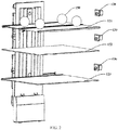
- Fig. 2 is a schematically structural view of internal components of a refrigerating chamber of a refrigerator suitable for a partition refrigeration control device for the refrigerating chamber of the refrigerator according to an embodiment of the present invention.
- the refrigerating chamber is divided into a plurality of item storage compartments 140 through the shelf assembly 120.
- a preferable structure is that the shelf assembly 120 comprises at least one horizontally arranged partition to divide the refrigerating chamber into the plurality of item storage compartments 140 in the vertical direction.
- the shelf assembly 120 comprises a first partition plate 121, a second partition plate 122 and a third partition plate 133, wherein a first item storage compartment is formed above the first partition plate 121, a second item storage compartment is formed between the first partition plate 121 and the second partition plate 122, and a third item storage compartment is formed between the second partition plate 122 and the third partition plate 123.
- the number of the partition plates in the shelf assembly 120 and the number of the item storage compartments 140 may be preset according to the volume of the refrigerator and use requirements.
- each infrared sensing device 130 is arranged on the inner wall of the refrigerator body 110 of the corresponding item storage compartment 140, and is configured to sense infrared radiation energy emitted by an item 150 placed in the item storage compartment 140 to determine a surface temperature of the item 150.
- a first infrared sensing device is arranged in the first item storage compartment; a second infrared sensing device is arranged in the second item storage compartment; and a third infrared sensing device is arranged in the third item storage compartment.
- the number of the infrared sensing devices is set in accordance with the number of the item storage compartments 140.
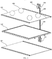
- Fig. 3 is a schematically structural view of internal components of a refrigerating chamber of a refrigerator suitable for a partition refrigeration control device for the refrigerating chamber of the refrigerator according to another embodiment of the present invention.
- a helical driving assembly 300 is adopted to drive the infrared sensing device 130 to sense temperatures of items in the plurality of item storage compartments.
- the helical driving assembly 300 is vertically arranged inside the refrigerating chamber, and comprises a screw rod 310, a nut 320 and a limiting component.
- the screw rod 310 is vertically arranged and penetrates through the plurality of item storage compartments 140.
- the nut 320 is threadedly meshed with the screw rod 310.
- the limiting component is configured to limit a rotation angle of the nut 320 relative to the refrigerating chamber, so that the screw rod 310 can drive the nut 320 to move vertically when rotating around its axis as the center.
- the screw rod 310 may be driven by a driving motor 311 to rotate around its axis as the center.
- the nut 320 can move vertically during the rotation of the screw rod 310.
- the screw rod 310 and the nut 320 may adopt a sliding helical driving mode or a rolling helical driving mode to change a rotational movement to a linear movement so as to drive the nut 320 to move vertically.
- the infrared sensing device 130 is fixedly arranged on the nut 320, faces the refrigerating chamber, and is configured to sense infrared radiation energy emitted by the items 150 placed in the plurality of item storage compartments 140 to determine the surface temperature of each item 150.
- the above-mentioned helical driving assembly 300 and the infrared sensing device 130 may be arranged on any side wall or a back plate of the refrigerator body 110, and preferably, are arranged on the back plate of the refrigerator body.
- a sensing position is preset on the helical driving assembly 300 at a predetermined height within each item storage compartment 140, so that the infrared sensing device 130 can sense the temperature of the item storage compartment after moving to the sensing position.
- the sensing positions may be preset according to the internal space of the refrigerator.
- the screw rod 310 is driven to stop rotating at the predetermined height of each item storage compartment.
- the infrared sensing device 130 is driven to move upwards or downwards to the sensing position of the adjacent item storage compartment.
- Fig. 4 is a schematically structural view of a driving mechanism for an infrared sensing device in a refrigerator suitable for a partition refrigeration control device for a refrigerating chamber of a refrigerator according to another embodiment of the present invention.
- the infrared sensing device 130 is moved by a synchronous belt driving assembly 400.
- the synchronous belt driving assembly 400 is arranged in the refrigerating chamber; a synchronous belt 422 of the synchronous belt driving assembly is in a vertical plane, and comprises a vertical section which is vertically arranged and penetrates through the plurality of item storage compartments 140.
- the synchronous belt driving assembly is realized by a circular belt whose inner circumferential surface is provided with uniformly-spaced teeth and gears correspondingly matched with the same, and combines advantages of belt driving, chain driving and gear driving. When in rotation, power is transmitted by the belt teeth and gear tooth troughs meshed with the same.
- a sliding block 420 is fixedly arranged on the vertical section of the above synchronous belt 422 to be moved vertically under the driving of the synchronous belt driving assembly 300; the infrared sensing device 130 is fixedly arranged on the sliding block 420, faces the refrigerating chamber, and is configured to sense infrared radiation energy emitted by the items 150 placed in the plurality of item storage compartments 140 to determine the surface temperature of each item 150.
- the synchronous belt driving assembly 400 may be arranged on any side wall or the back plate of the refrigerator body 110, and preferably, is arranged on the side wall.
- the infrared sensing device 130 senses infrared rays through a sensing device cover plate made of an infrared ray transmission material.
- the surface, facing the refrigerating chamber, of the sensing device cover plate may be flush with the inner surface of each side wall to improve the appearance of the refrigerating chamber of the refrigerator and the neatness of the item storage compartments 140.
- a drive gear 421 in the synchronous belt driving assembly 400 is arranged at the bottom end of the synchronous belt driving assembly 400, and is rotated under the driving of the driving motor 425 to drive the synchronous belt 422.
- a driven gear 424 in the synchronous belt driving assembly 400 is arranged at the top end of the same.
- the inner side of the synchronous belt 422 winds the outer edges of both the drive gear 421 and the driven gear 424; and the teeth of the synchronous belt 422 are meshed with the tooth troughs of the drive gear 421 and of the driven gear 424, so that the driven gear 424 is moved under the driving of the drive gear 421.
- the drive gear 421 and the driven gear 424 may tension the synchronous belt 422 to convert a rotational movement to a linear movement of the sliding block 420.
- the drive gear 421 and the driven gear 424 have the same gear diameter and tooth pitch, and a center line of the drive and driven gears is vertical.
- the synchronous belt driving assembly 400 may also be provided with a guide bar 423 parallel to the vertical section; and the sliding block 420 is provided with a through hole through which the guide bar 323 penetrates, so that a moving direction of the infrared sensing device 130 is limited through the guide bar 423.
- a sensing position on the guide bar 423 is preset at a predetermined height within each item storage compartment 140, so that the infrared sensing device 130 can sense the temperature of the item storage compartment after moving to the sensing position.
- the sensing position on the synchronous belt driving assembly 400 is preset at the predetermined height within each item storage compartment 140, so that the infrared sensing device 130 can sense the temperature of the item 150 in the item storage compartment 140 after moving to the sensing position.
- the sensing positions may be preset according to the internal space of the refrigerator.
- the infrared sensing device 130 shown in any of Figs. 2-4 does not emit infrared rays, but passively receives infrared rays emitted by the items 150 in the sensed spaces and background infrared rays, directly senses a temperature change range and the temperature of each item in each refrigerator, and converts them to a corresponding electrical signal.
- the infrared sensing device 130 provided by the present invention may detect the infrared rays in the whole item storage compartments 140, rather than merely detecting the position of a heat source point.
- the infrared sensing device 130 may be an infrared receiver having a rectangular field of view that may be configured to enable a projection of an infrared receiving range of the infrared receiver on a horizontal plane to cover the partition plates, so that the infrared sensing device 130 can sense infrared radiation energy released by the items placed on the partition plates.
- the infrared receiver may limit the above rectangular view by arranging an infrared guide component; and the detection accuracy may be improved by limiting a detection direction to accurately detect the item storage compartments. The difference between the different embodiments described above only lies in the manners of sensing the temperatures of the items in the item storage compartments by the infrared sensing device 130.
- the plurality of infrared sensing devices 130 is adopted to sense the temperatures respectively; and one infrared sensing device 130 is driven through the helical driving mode or the synchronous belt driving mode to sense the temperatures of the items in the item storage compartments.
- the refrigerator in the present embodiment may be also provided with a refrigerating environment temperature sensing device (not shown) for sensing an average environment temperature in the refrigerating chamber.
- the partition refrigeration control device for the refrigerating chamber of the refrigerator may be implemented by a temperature sensor such as a thermistor.
- the refrigeration of the refrigerator in the present embodiment may be controlled according to the temperatures of the items determined by the infrared sensing device 130 and the environment temperature in the refrigerating chamber.
- the refrigerator suitable for the partition refrigeration control device for the refrigerating chamber of the refrigerator in the present embodiment may be an air-cooled refrigerator.
- Fig. 5 is a schematic view of a refrigeration system of a refrigerator suitable for a partition refrigeration control device for a refrigerating chamber of the refrigerator according to an embodiment of the present invention.
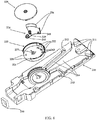
- Fig. 6 is a schematic view of an air duct assembly in a refrigeration system of a refrigerator suitable for a partition refrigeration control device for a refrigerating chamber of the refrigerator according to an embodiment of the present invention.
- the refrigeration system comprises the air duct assembly, a compressor, a refrigerating air gate 250, a fan 230, and the like.
- the refrigerator can use an evaporator, the compressor, a condenser, a throttle component and other components to form a refrigeration circulation loop through a refrigerant pipe; and the evaporator releases cold energy after the compressor is started.
- the evaporator may be arranged in an evaporator chamber. Air cooled by the evaporator is conveyed to a storage chamber via the fan 230.
- a storage chamber For example, the interior of the storage chamber of the refrigerator can be separated into a variable temperature chamber, a refrigerating chamber and a freezing chamber, wherein the uppermost layer of the storage chamber is the refrigerating chamber, the variable temperature chamber is arranged below the refrigerating chamber, the freezing chamber is arranged below the variable temperature chamber, and the evaporator chamber may be arranged in back of the freezing chamber.
- the fan 230 is arranged at an exit above the evaporator chamber.
- an air supply path for supplying the air cooled by the evaporator comprises a variable temperature air supply path configured to supply air to the variable temperature chamber and connected to the same, a freezing air supply path for supplying air to the freezing chamber and connected to the same, and a refrigerating air supply path for supplying air to the refrigerating chamber and connected to the same.
- the air duct assembly is an air path system for blowing air to the refrigerating chamber, and comprises an air duct bottom plate 210, a split air blowing device 220 and the fan 230.
- a plurality of air paths 214 defined on the air duct bottom plate 210 leads to the plurality of item storages compartments 140, respectively.
- the split air blowing device 220 is arranged in the refrigerating air supply path which is formed in the back of the refrigerating chamber, and comprises an air inlet 221 connected to a cold source (for example, the evaporator chamber) and a plurality of distribution ports 222 connected to the plurality of air paths 214.
- the distribution ports 222 are connected to the different air paths 214, respectively.
- the split air blowing device 220 may controllably distribute cold air from the cold source and generated by the fan 230 to the different distribution ports 222 via the air inlet 221, so that the cold air can enter the different item storage compartments 140 through the different air paths 214.
- the split air blowing device 220 can centrally distribute the refrigeration air flow from the cold source, instead of arranging the different air paths for the different item storage compartments 140, respectively, thereby improving the refrigeration efficiency.
- the split air blowing device 220 may comprise a casing 223, an adjustment part 224 and a cover plate 225.
- the air inlet 221 and the distribution ports 222 are formed in the casing 223; and the cover plate 225 is assembled with the casing 223 to form a split air blowing chamber in which the adjustment part 224 is arranged.
- the adjustment part 224 is provided with at least one shielding part 226 which is movably arranged in the casing 223 and configured to shield the plurality of distribution ports 222 to adjust an air outlet area of each distribution port 222.
- Air from the fan 230 is distributed to the different item storage compartments 140 through the distribution of the adjustment part 224.
- the split air blowing device 220 can achieve up to seven air blowing states.
- the distribution port 222 corresponding to the first air supply port 211 is opened separately; the distribution port 222 corresponding to the second air supply port 212 is opened separately; the distribution port 222 corresponding to the third air supply port 213 is opened separately; the distribution ports 222 corresponding to the first and second air supply ports 211 and 212 are opened simultaneously; the distribution ports 222 corresponding to the first and third air supply ports 211 and 213 are opened simultaneously; the distribution ports 222 corresponding to the second and third air supply ports 212 and 213 are opened simultaneously; and the distribution ports 222 corresponding to the first, second and third air supply ports 211, 212 and 213 are opened simultaneously.
- the split air blowing device 220 may be provided with two distribution ports, and there may be three air blowing states.
- the adjustment part 224 is rotated with a rotation angle determined according to a required air volume, and guide ports formed between the shielding parts 226 are aligned to the corresponding distribution ports 222.
- the casing 223 is provided with a motor 227, two stopper posts 228, and a positioning holder recess 243 in the split air blowing chamber.
- the action of the stopper posts 228 is that during operating of the motor 227, the movement of the adjustment part 224 is more accurate.
- the adjustment part 224 moves to any starting stopper post 228 and then rotates to a designated rotational position by taking the stopper post as the starting point.
- the action of the positioning holder recess 243 is to ensure that the adjustment part 224 is positioned at an angular position where it rotates by 30 degrees every time.
- the adjustment part 224 is provided with a disk spring 229 (the disk spring 229 may be replaced by a torsion spring), a counterweight 241 and a positioning pin 245.
- a section of the disk spring 229 is fixed onto the cover plate 225, and the other end thereof is pre-tensioned to apply an opposite force along with the rotation of the adjustment part 224; and a constant biasing force is always applied to the adjustment part 224 to prevent a shaking problem caused by a tooth clearance of a driving mechanism of a direct-current step motor 227.
- a counterweight portion is formed in the extending direction, opposite to the radial direction of a main body of the adjustment part 224, of a pivotal portion; and the counterweight 241 is arranged at the far end of the counterweight portion to eliminate a bias torque.
- the positioning pin 245 is fixed on the adjustment part 224 and can move vertically (through a compression spring) on the same.
- the casing 223 is provided with the positioning holder recess 243 cooperating therewith.
- the refrigerator having three item storage compartments 140 is taken as an example to describe.
- the numbers of the infrared sensing device 130, the air path 214, the distribution port 222, and the air supply port may be set according to the specific use requirements to meet the requirements of different refrigerators. For example, according to the above description, it is easy to obtain an air blowing system of a refrigerating chamber having two refrigerating item storage compartments.
- a partition refrigeration control device 700 for a refrigerating chamber of a refrigerator is configured to perform partition control on the refrigerating chamber of the above refrigerator.
- Fig. 7 is a schematic block diagram of a partition refrigeration control device for a refrigerating chamber of a refrigerator according to an embodiment of the present invention.
- the partition refrigeration control device 700 for the refrigerating chamber of the refrigerator generally comprises: a state determination module 702, a first temperature acquisition module 704, a first comparison module 706, an identifier setting module 708 and a driving module 710.
- a second temperature acquisition module 712, an environment temperature judgment module 714, an air gate control module 716, a second comparison module 718, an initialization module 720 and a third temperature acquisition module 722 are further arranged, and can be configured flexibly according to the actual configuration conditions of the refrigerator and use requirements. In some alternative embodiments, some or all of the above modules may be configured.
- the state determination module 702 may be configured to determine that the refrigerating chamber enters a refrigeration state.
- the refrigeration state may be started after an average environment temperature, sensed by the refrigerating environment temperature sensing device, in the refrigerating chamber is higher than or equal to a preset overall refrigeration start temperature threshold.
- An alternative step of determining by the state determination module 702 that the refrigerating chamber enters the refrigeration state comprises: acquiring by the second temperature acquisition module 712 the average environment temperature in the refrigerating chamber through the refrigerating environment temperature sensing device; judging by the environment temperature judgment module 714 whether the average environment temperature in the refrigerating chamber is higher than or equal to the preset overall refrigeration start temperature threshold or not; and opening by the air gate control module 716 a refrigerating air gate arranged between a cold source and a split air blowing device to enable the refrigerating chamber to enter the refrigeration state if a judgment result of the environment temperature judgment module 714 is YES.
- the first temperature acquisition module 704 may acquire the temperatures, sensed by the infrared temperature sensing device, of the items stored in the plurality of item storage compartments.
- the temperatures of the items stored in the plurality of item storage compartments may be detected after one infrared sensing device 130 is moved to the sensing position of each item storage compartment, or may be sensed by the plurality of infrared sensing devices 130 distributed in the plurality of item storage compartment, respectively.
- the first comparison module 706 may be configured to compare the temperature of the item stored in each item storage compartment with a corresponding preset area refrigeration start temperature threshold of each item storage compartment.
- the identifier setting module 708 is configured to set a refrigeration state identifier corresponding to the item storage compartment in which the temperature of the item is higher than the corresponding area refrigeration start temperature threshold as start.
- the driving module 710 is configured to drive the split air blowing device to operate in a state of providing the cooling air flow to the item storage compartment whose refrigeration state identifier is start.
- the air gate control module 716 is configured to: judge whether the refrigerating air gate is already in an open state or not when the average environment temperature in the refrigerating chamber is less than the preset overall refrigeration start temperature threshold; if yes, judge whether the average environment temperature in the refrigerating chamber and/or the temperature of the item in each item storage compartment meet(s) a preset refrigeration stop condition of the refrigerating chamber or not; and if the preset refrigeration stop condition of the refrigerating chamber is met, close the refrigerating air gate.
- the above refrigeration stop condition of the refrigerating chamber may comprise: the temperature of the item stored in each item storage compartment being less than a corresponding preset area refrigeration stop temperature threshold of each item storage compartment, wherein the area refrigeration stop temperature threshold of each item storage compartment is less than the corresponding area refrigeration start temperature threshold; or the average environment temperature in the refrigerating chamber being less than a preset overall refrigeration stop temperature threshold.
- Another alternative refrigeration stop condition of the refrigerating chamber comprises: the temperature of the item stored in each item storage compartment being less than a corresponding preset area refrigeration start temperature threshold of each item storage compartment when the average environment temperature in the refrigerating chamber is less than the preset overall refrigeration stop temperature threshold, wherein the area refrigeration stop temperature threshold of each item storage compartment is less than the corresponding area refrigeration start temperature threshold; or a difference value obtained by subtracting the average environment temperature in the refrigerating chamber from the preset overall refrigeration stop temperature threshold being greater than a preset margin value.
- the second comparison module 718 is configured to compare the temperature of the item stored in each item storage compartment with a corresponding preset area refrigeration stop temperature threshold of each item storage compartment, wherein the area refrigeration stop temperature threshold of each item storage compartment is smaller than the area refrigeration start temperature threshold thereof.
- the identifier setting module 708 is further configured to set a refrigeration state identifier corresponding to the item storage compartment in which the temperature of the item is less than the corresponding area refrigeration stop temperature threshold as stop.
- the initialization module 720 may be configured to acquire a powering-on and starting signal of the refrigerator, and initialize a refrigeration system of the refrigerator.
- the refrigeration system comprises: a compressor, the refrigerating air gate, a fan and the split air blowing device.
- the initialization module 720 may be further configured to power off the compressor and the fan, close the refrigerating air gate, and drive the split air blowing device to operate to the initial position.
- the third temperature acquisition module 722 in the partition refrigeration control device 700 may be further configured to acquire a temperature of the freezing chamber, and perform refrigeration control on the freezing chamber according to the temperature of the freezing chamber.
- the third temperature acquisition module performs refrigeration judgment on the freezing chamber according to the temperature of the freezing chamber, and adjusts a start/stop state of the compressor, the fan and the refrigerating air gate according to a judgment result.
- the state determination module 702 is configured to start the step of determining that the refrigerating chamber enters the refrigeration state after the refrigeration judgment of the freezing chamber is finished.
- the embodiments of the present invention further provide a partition refrigeration control method for a refrigerating chamber of a refrigerator.
- the partition refrigeration control method for the refrigerating chamber of the refrigerator may be executed by the partition refrigeration control device 700 for the refrigerating chamber of the refrigerator provided by any of the above embodiments, so as to realize partition refrigeration of the refrigerating chamber of the refrigerator.
- Fig. 8 is a schematic view of a partition refrigeration control method for a refrigerating chamber of a refrigerator according to an embodiment of the present invention.
- the partition refrigeration control method for the refrigerating chamber of the refrigerator comprises:
- determining that the refrigerating chamber enters the refrigeration state further comprises: acquiring the average environment temperature in the refrigerating chamber; judging whether the average environment temperature in the refrigerating chamber is higher than or equal to a preset overall refrigeration start temperature threshold; and if yes, opening a refrigerating air gate arranged between a cold source and the split air blowing device to enable the refrigerating chamber to enter the refrigeration state.
- whether the refrigerating air gate is already in an open state or not is judged when the average environment temperature in the refrigerating chamber is less than the preset overall refrigeration start temperature threshold; if yes, whether the average environment temperature in the refrigerating chamber and/or the temperature of the item in each item storage compartment meet(s) a preset refrigeration stop condition of the refrigerating chamber or not is judged; and if the preset refrigeration stop condition of the refrigerating chamber is met, the refrigerating air gate is closed.
- the above refrigeration stop condition of the refrigerating chamber may comprise: the temperature of the item stored in each item storage compartment being less than a corresponding preset area refrigeration stop temperature threshold of each item storage compartment, wherein the area refrigeration stop temperature threshold of each item storage compartment is less than the corresponding area refrigeration start temperature threshold; or the average environment temperature in the refrigerating chamber being less than a preset overall refrigeration stop temperature threshold.
- Another alternative refrigeration stop condition of the refrigerating chamber comprises: the temperature of the item stored in each item storage compartment being less than a corresponding preset area refrigeration start temperature threshold of each item storage compartment when the average environment temperature in the refrigerating chamber is less than the preset overall refrigeration stop temperature threshold, wherein the area refrigeration stop temperature threshold of each item storage compartment is less than the corresponding area refrigeration start temperature threshold; or a difference value obtained by subtracting the average environment temperature in the refrigerating chamber from the preset overall refrigeration stop temperature threshold being greater than a preset margin value.
- the method may further comprise: comparing the temperature of the item stored in each item storage compartment with the corresponding preset area refrigeration stop temperature threshold of each item storage compartment, wherein the area refrigeration stop temperature threshold of each item storage compartment is smaller than the area refrigeration start temperature threshold thereof; and setting the refrigeration state identifier corresponding to the item storage compartment in which the temperature of the item is less than the corresponding area refrigeration stop temperature threshold as stop.
- the method further comprises: acquiring a powering-on and starting signal of the refrigerator; and initializing a refrigeration system of the refrigerator, the refrigeration system comprising a compressor, the refrigerating air gate, a fan and the split air blowing device.
- the above initializing process may comprise: powering off the compressor and the fan, closing the refrigerating air gate, and driving the split air blowing device to operate to the initial position.
- the freezing chamber may be subjected to refrigeration control first; and after the refrigeration control of the freezing chamber is completed, step S802 and the followed steps for partition refrigeration of the refrigerating chamber are executed.
- An alternative flow for control of the freezing chamber comprises: acquiring a temperature of the freezing chamber, and performing refrigeration control on the freezing chamber according to the temperature of the freezing chamber. For example, refrigeration judgment of the freezing chamber is performed according to the temperature of the freezing chamber, and a start/stop state of the compressor, the fan and the refrigerating air gate is adjusted according to the judgment result. Step S802 is executed after the refrigeration judgment of the freezing chamber is completed.
- the partition refrigeration control method for the refrigerating chamber of the refrigerator provided by the present embodiment can control the temperatures of the plurality of item storage compartments of the refrigerating chamber respectively, so that the storage effect of the items in the refrigerating chamber is improved.
- the partition refrigeration control method and device are introduced below by taking the refrigerating chamber with three item storage compartments as an example.
- the following parameters comprising an area refrigeration start temperature threshold, an area refrigeration stop temperature threshold, an overall refrigeration start temperature threshold, an overall refrigeration stop temperature threshold, a set temperature of the refrigerating chamber, and a set temperature of the freezing chamber can be predetermined according to the features of the refrigerating chamber of the refrigerator and the types of the stored items.
- Table 1 shows a parameter table set for partition refrigeration of the refrigerating chamber with three item storage compartments.
- a temperature value of the freezing chamber detected by the sensor is FT; the set temperature of the freezing chamber is F-set; the refrigeration start temperature threshold is F-on; and the refrigeration stop temperature threshold is F-off.
- F-set may be set by a user or may be a default value; F-on and F-off may be determined according to F-set; and generally, they meet the relationship of F-on>F-set>F-off.
- the average environment temperature, sensed by the refrigerating environment temperature sensing device, in the refrigerating chamber is RT; the temperature set for the refrigerating chamber is R-set; the overall refrigeration start temperature threshold is R-on; and the overall refrigeration stop temperature threshold is R-off.
- R-set may be set by the user or may be a default value; R-on and R-off may be determined according to R-set; and generally, they meet the relationship of R-on>R-set>R-off.
- the maximum temperature, sensed by the infrared sensing device, of an item stored in the first item storage compartment is IRT1; the area refrigeration start temperature threshold of the first item storage compartment is IR1-on; and the area refrigeration stop temperature threshold of the first item storage compartment is IR1-off.
- the IR1-on and IR1-off may be determined according to R-set and the type of the item stored in the first item storage compartment; and generally, they meet the relationship of IR1-on>IR1-off.
- the maximum temperature, sensed by the infrared sensing device, of an item stored in the second item storage compartment is IRT2; the area refrigeration start temperature threshold of the second item storage compartment is IR2-on; and the area refrigeration stop temperature threshold of the second item storage compartment is IR2-off.
- IR2-on and IR2-off may be determined according to R-set and the type of the item stored in the second item storage compartment; and generally, they meet the relationship of IR2-on>IR2-off.
- the maximum temperature, sensed by the infrared sensing device, of an item stored in the third item storage compartment is IRT3; the area refrigeration start temperature threshold of the third item storage compartment is IR3-on; and the area refrigeration stop temperature threshold of the third item storage compartment is IR3-off.
- IR3-on and IR3-off may be determined according to R-set and the type of the item stored in the third item storage compartment; and generally, they meet the relationship of IR3-on>IR3-off.
- the area refrigeration start temperature thresholds IR1-on, IR2-on and IR3-on may be set to be the same or different; and the area refrigeration start temperature thresholds IR1-off, IR2-off and IR3-off may be set to be the same or different.
- Each item storage compartment may also be pre-configured with a refrigeration state identifier configured to indicate whether air needs to be blown into the item storage compartment or not.
- the refrigeration identifier of the first item storage compartment is gate 1; the refrigeration identifier of the second item storage compartment is gate 2; and the refrigeration identifier of the third item storage compartment is gate 3.
- the above-mentioned gate 1, gate 2 and gate 3 can be set as start or stop. For example, "0" represents stop and "1" represents start.
- Fig. 9 is a block diagram of an overall flow of a partition refrigeration control method for a refrigerating chamber of a refrigerator according to an embodiment of the present invention.
- a refrigeration controller for the refrigerator performs the following steps:
- step S908 After step S908 is completed, the flow returns to step S906 to execute a judgment flow for refrigeration control of the freezing chamber.
- Fig. 10 is a flow chart of the initialization of a refrigeration system of a refrigerator in a partition refrigeration control method for a refrigerating chamber of the refrigerator according to an embodiment of the present invention.
- the initialization flow comprises the following steps:
- the default state may be restored, so that control logic confusion caused by an improper operation of a component during the last power failure is avoided.
- Fig. 11 is a logic flow chart of refrigeration control of a freezing chamber in a partition refrigeration control method for a refrigerating chamber of a refrigerator according to an embodiment of the present invention. After the refrigeration control of the freezing chamber is started, the following steps may be executed:
- Fig. 12 is a logic flow chart of an accelerated refrigeration flow in a partition refrigeration control method for a refrigerating chamber of a refrigerator according to an embodiment of the present invention.
- the accelerated refrigeration flow is suitable for a condition that food with a high temperature is placed in any item storage compartment in the refrigerating chamber of the refrigerator, wherein the temperature of the food may be significantly higher than the compartment temperature and the set temperature R-set of the refrigerating chamber.
- the accelerated refrigeration flow mainly comprises the following steps.
- step S1202 after the refrigeration control of the freezing chamber is completed, the partition refrigeration of the refrigerating chamber is started. This step may be performed after step S1116 shown in Fig. 11 .
- step S1204 the compressor and the fan are driven to operate at a high speed, and the refrigerating air gate is opened.
- a specific implementation flow of step S1204 comprises: first, judging whether any of conditions IRT1>IR1-on+M, IRT2>IR2-on+M, and IRT3>IR3-on+M exists, wherein M is a preset constant, and represents that there is an item whose temperature is M degrees higher than the refrigeration start temperature threshold of the first item storage compartment, that is, the high temperature item is stored in the first item storage compartment; if yes, driving the fan to operate at a high speed, and enabling the compressor to operate at a high speed; or if not, judging whether the compressor is in a high speed state, if not, executing step S 1214, or if yes, directly opening the refrigerating air gate.
- Each of the processes of driving the fan, the compressor and the refrigerating air gate in step S1204 comprises a state judgment process. If it is determined that the fan, or the compressor, or the refrigerating air gate is already in a required state, there is no need to repeat control. After the compressor and the fan are driven to operate at a high speed and the refrigerating air gate is opened, step S1206 is executed.
- step S1206 refrigeration identifiers are determined through the start temperature thresholds and stop temperature thresholds set for the plurality of item storage compartments.
- the first item storage space is taken as an example to introduce. Whether IRT1>IR1-on is judged; if yes, gate 1 is set as start, or if not, it is judged that gate 1 is already in the start state; if gate 1 is in the stop state, judgment is performed for the next item storage compartment; if gate 1 is in the start state, whether IRT1 ⁇ IR1-off is judged; if yes, gate 1 is set as stop and judgment is performed for the next item storage compartment; or if not, judgment is directly performed for the next item storage compartment.
- the judgment process similar to that of the first item storage compartment may be adopted.
- the judgment processes for the three item storage compartments are taken as an example. In an actual use process, the judgment processes can be increased or decreased according to the number of item storage compartments, and the time sequences of the judgment processes of all item storage compartments are not limited, and may be performed one by one or in parallel.
- step S1208 operating states of the split air blowing device are determined according to the states of gate 1, gate 2, and gate 3 set in step S1206, and the air blowing device is driven to operate in this state.
- Figs. 13-20 show eight operating states of the split air blowing device, respectively.
- Fig. 13 shows an initial state of the split air blowing device. From the initial state, the adjustment part 224 is controlled to rotate clockwise by a predetermined angle to enable a positioning pin 245 to be inserted into one of positioning recesses 243; and the shielding parts 226 are adopted to shield different distribution ports respectively to enable the cooling air flow to enter the corresponding item storage compartments.
- Fig. 13 shows an initial state of the split air blowing device. From the initial state, the adjustment part 224 is controlled to rotate clockwise by a predetermined angle to enable a positioning pin 245 to be inserted into one of positioning recesses 243; and the shielding parts 226 are adopted to shield different distribution ports respectively to enable the cooling air flow to enter the corresponding item storage compartments
- FIG. 14 shows a first state of the split air blowing device, wherein the first distribution port is shielded, and the second distribution port and the third distribution port are opened.
- Fig. 15 shows a second state of the split air blowing device, wherein the second distribution port is shielded, and the first distribution port and the third distribution port are opened.
- Fig. 16 shows a third state of the split air blowing device, wherein the second distribution port is opened, and the first distribution port and the third distribution port are shielded.
- Fig. 17 shows a fourth state of the split air blowing device, wherein the third distribution port is opened, and the first distribution port and the second distribution port are shielded.
- Fig. 18 shows a fifth state of the split air blowing device, wherein the first distribution port is opened, and the second distribution port and the third distribution port are shielded.
- Fig. 19 shows a sixth state of the split air blowing device, wherein the first and second distribution ports are opened, and the third distribution port is shielded.
- Fig. 20 is the seventh state of the split air blowing device, wherein the adjustment part 224 is abutted against the other stopper post, and all of the first, second and third distribution ports are opened.
- Table 2 shows corresponding relationships between set operating states of the split air blowing device for partition refrigeration of the refrigerating chamber having three item storage compartments and refrigeration identifiers of all item storage compartments.
- Table 2 Refrigeration identifier of item storage compartment State 1 State 2 State 3 State 4 State 5 State 6 State 7 gate 1 Off On Off Off On On On gate 2 On Off On Off Off On On gate 3 On On Off On Off Off Off On On On On On On Off Off On On On
- the states of the split air blowing device may be adjusted if there are two or more than three item storage compartments.
- step S1210 whether the accelerated refrigeration flow is completed or not is judged according to the refrigeration condition.
- a specific implementation flow of step S1210 comprises: first, judging whether the temperature of a current item storage spaces satisfies IRT1 ⁇ IR1-off, IRT2 ⁇ IR2-off and IRT3 ⁇ IR3-off at the same time or not; if yes, closing the air gate and exiting the high rotation state, or if not, judging whether RT is smaller than R-off or not; if not, proceeding to step S1212, or if yes, judging whether the temperature of the item storage spaces satisfies IRT1 ⁇ IR1-on, IRT2 ⁇ IR2-on and IRT3 ⁇ IR3-on at the same time or not; if yes, similarly, closing the air gate and exiting the high rotation state, or if not, judging whether RT is smaller than (R-off-k), that is, judging whether the average environment temperature RT in the refrigerating chamber is k degrees lower than R-off or not,
- step S1212 is directly proceeded.
- step S1212 the refrigeration control process of the freezing chamber is returned. For example, it returns to step S1102.
- step S1214 the normal partition refrigeration control flow is executed.
- Fig. 21 is a logic flow chart of a normal refrigeration flow in a partition refrigeration control method for a refrigerating chamber of a refrigerator according to an embodiment of the present invention.
- the normal refrigeration flow is suitable for a condition that an average temperature of the refrigerating chamber of the refrigerator is increased, and refrigeration is performed based on the situation of an item storage compartment.
- the normal refrigeration flow mainly comprises the following steps.
- step S2102 partition refrigeration of the refrigerating chamber is started, and this step may be performed after step S1214 shown in Fig.12 .
- step S2104 the fan and the refrigerating air gate are driven to be started.
- a specific implementation flow of step S2104 comprises: judging whether RT is greater than R-on or not first; if RT is greater than R-on, judging whether the fan is started or not; if the fan is started, enabling the refrigerating air gate to be in a start state, and then directly proceeding to step S2108; if the fan is not started, returning to step S2112; if RT is smaller than or equal to R-on, judging whether the refrigerating air gate is in the start state or not; if yes, proceeding to step S2104; or if not, returning to step S2112.
- step S2106 whether the average environment temperature in the refrigerating chamber and/or the temperature of the article in each storage space meet(s) a preset refrigeration stop condition of the refrigerating chamber or not is judged; if yes, the refrigerating air gate is closed, and then directly return to step S2112; or if not, step S2108 is executed.
- step S2108 the refrigeration identifiers are determined according to the start temperature thresholds and stop temperature thresholds set for the plurality of item storage compartments. This step is basically the same as the judgment flow in step S1206 shown in Fig. 12 , and is implemented by judging the plurality of item storage compartments, respectively, and determining the refrigeration identifier of each item storage compartment.
- step S2110 the operating states of the split air blowing device are determined according to the states of gate 1, gate 2, and gate 3 set in step S2108, and the air blowing device is driven to operate in this state.
- This step is basically the same as the flow of step S1208 shown in Fig. 12 .
- the corresponding relationships between the operating states of the split air blowing device and the gate 1, gate 2 and gate 3 are shown in Table 2.
- step S211 return to the refrigeration control process of the freezing chamber. For example, return to step S1102.
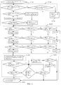
- Fig. 22 is a logic flow chart of determination of refrigeration stop in a partition refrigeration control method for a refrigerating chamber of a refrigerator according to an embodiment of the present invention. After a refrigeration stop judgment flow of the refrigerating chamber is started in step S2202, the following steps are performed sequentially.
- step S2204 whether IRT1 ⁇ IR1-off, IRT2 ⁇ IR2-off and IRT3 ⁇ IR3-off are satisfied at the same time or not are judged; if yes, the refrigerating air gate is closed and step S2112 in Fig. 21 is executed; or if not, step S2206 is executed.
- step S2206 whether RT is smaller than R-off or not is judged, that is, whether the average environment temperature in the refrigerating chamber is lower than the preset stop temperature threshold or not is judged; if yes, the judgment flow in step S2208 is executed; and if not, step S2108 shown in Fig. 21 is directly executed.
- step S2208 whether IRT1 ⁇ IR1-on, IRT2 ⁇ IR2-on and IRT3 ⁇ IR3-on are satisfied at the same time or not are judged; if yes, the refrigerating air gate is closed and step S2112 in Fig. 21 is executed; or if not, the judgment flow in step S2210 is executed.
- step S2210 whether RT is smaller than (R-off-k) or not is judged, that is, the average environment temperature RT in the refrigerating chamber is k degrees lower than R-off or not is judged, in other words, whether a difference value obtained by subtracting RT from R-off is greater than k or not is judged, k being a preset constant and representing a preset margin value; if yes, the refrigerating air gate is closed, and step S2112 shown in Fig. 21 is executed; or if not, step S2108 shown in Fig. 21 is directly executed.
- Fig. 22 shows an optional refrigeration stop condition of the refrigerating chamber.
- steps of S2204 and S2206 need to be executed. If it is determined that RT is smaller than R-off, step S2112 shown in Fig. 21 is executed; or if RT is greater than or equal to R-off, step S2108 shown in Fig. 21 is executed directly, and steps S2208 and S2210 are omitted. Tests show that the refrigeration stop condition without the omitted steps can also achieve the control effect, but its effect is inferior to that of the complete flow shown in Fig. 22 .
- the partition refrigeration control method is suitable for various conditions of multiple item storage compartments, and effectively meets requirements on refrigeration control of the refrigerating chamber. It should be noted that the present method is not limited to control of a refrigerating chamber having three item storage compartments, and is also suitable for split air blowing and refrigeration control of a refrigerating chamber having two item storage compartments or more than three item storage compartments by simple deformation.
- the partition refrigeration control method and device for the refrigerating chamber of the refrigerator provided by the present embodiment are suitable for a case where the refrigerating chamber of the refrigerator is divided into the plurality of item storage compartments.
- the infrared sensing device is adopted to sense the temperatures of the items stored in the plurality of item storage compartments; the position and the temperature of a heat source in the refrigerator are accurately determined by receiving infrared radiation energy released from the items placed in the refrigerator; and the sensed temperatures of the items stored in the refrigerator are compared with the preset area refrigeration start temperature thresholds thereof, and a refrigeration state of each item storage compartment is determined in accordance with the comparison results.
- the split air blowing device distributes the cooling air flow to respective item storage compartments in accordance with the refrigeration state thereof, the control is more precise. Therefore, refrigeration control according to a condition of the item stored in the corresponding item storage compartment is ensured, and electric energy waste caused by refrigeration of the whole refrigerating chamber is avoided. Further, the partition refrigeration control method and device for the refrigerating chamber of the refrigerator provided by the present embodiment may quickly cool an item with a relatively higher temperature, and reduce the influence of the item with the relatively higher temperature on other items already stored in the refrigerator, so that the storage effect of the refrigerating chamber of the refrigerator is improved, and nutrient loss of food is reduced.
- a refrigeration mode of the refrigerating chamber is correspondingly adjusted by comprehensively judging the entire environment temperature in the refrigerating chamber and the temperature of the item stored in each item storage compartment, so that the refrigeration control flexibility of the refrigerating chamber is improved, and the requirements of different using habits of users are met.
Landscapes
- Engineering & Computer Science (AREA)
- Chemical & Material Sciences (AREA)
- Combustion & Propulsion (AREA)
- Physics & Mathematics (AREA)
- Mechanical Engineering (AREA)
- Thermal Sciences (AREA)
- General Engineering & Computer Science (AREA)
- Cold Air Circulating Systems And Constructional Details In Refrigerators (AREA)
- Devices That Are Associated With Refrigeration Equipment (AREA)
Abstract
Description
- The present invention relates to refrigerator control, and in particular, to a partition refrigeration control method and device for a refrigerating chamber of a refrigerator.
- Temperatures around temperature sensors arranged inside refrigerating chambers of existing refrigerators are generally sensed by the temperature sensors, and serve as a basis for refrigeration control.
- However, when the refrigerator is controlled through this control mode, refrigeration of the refrigerating chamber of the refrigerator is started once the temperature sensed by the temperature sensor is higher than a preset valve. In a case where the refrigerating chamber is divided into a plurality of relatively separate item storage compartments via shelving partition plates, the temperature of an item storage compartment where an item is just placed may be higher than that of another item storage compartment. If a temperature control method of the existing refrigerator is adopted, it is required to refrigerate the whole refrigerating chamber. As a result, electric energy is wasted, and particularly, is seriously wasted when the refrigerating chamber is larger in volume.
- In addition, in an actual use process of the refrigerating chamber of the refrigerator, a user often needs to place items in the refrigerator or take them out of the refrigerator. Generally, the temperature of an item just placed in the refrigerator is relatively high, and it requires certain time to conduct the temperature of the item to the whole refrigerating chamber in a heat radiation manner. The temperature sensed by the temperature sensor rises after the temperature of the item is conducted to the environment of the refrigerating chamber, and then a cold source device such as a compressor is started to refrigerate the refrigerating chamber. However, in this process, the temperature of the item may be conducted to another item in contact with the same, so that the temperature of the food stored in the refrigerator changes, resulting in nutrient loss and a poor storage effect.
- One object of the present invention is to reduce electric energy consumed by refrigeration of a refrigerator.
- Another object of the present invention is to improve an item storage effect of the refrigerator.
- Particularly, the present invention provides a partition refrigeration control method and device for a refrigerating chamber of a refrigerator. The refrigerating chamber of the refrigerator is divided into a plurality of item storage compartments; an infrared sensing device for sensing temperatures of items stored in the item storage compartments respectively is arranged in the refrigerating chamber; and the refrigerator is provided with a split air blowing device configured to distribute a cooling air flow from a cold source to the plurality of item storage compartments. The partition refrigeration control method comprises: determining that the refrigerating chamber enters a refrigeration state; acquiring the temperatures, sensed by the infrared sensing device, of the items stored in the plurality of item storage compartments; comparing the temperature of the item stored in each item storage compartment with a corresponding preset area refrigeration start temperature threshold of each item storage compartment; setting a refrigeration state identifier corresponding to the item storage compartment in which the temperature of the item is higher than the corresponding area refrigeration start temperature threshold as start; and driving the split air blowing device to operate in a state of providing the cooling air flow to the item storage compartment whose refrigeration state identifier is start.
- Optionally, the refrigerating chamber is further provided with a refrigerating environment temperature sensing device for sensing an average environment temperature in the refrigerating chamber. In the above partition refrigeration control method, determining that the refrigerating chamber enters the refrigeration state further comprises: acquiring the average environment temperature in the refrigerating chamber; judging whether the average environment temperature in the refrigerating chamber is higher than or equal to a preset overall refrigeration start temperature threshold; and if yes, opening a refrigerating air gate arranged between the cold source and the split air blowing device to enable the refrigerating chamber to enter the refrigeration state.
- Optionally, whether the refrigerating air gate is already in an open state or not is judged when the average environment temperature in the refrigerating chamber is less than the preset overall refrigeration start temperature threshold; if yes, whether the average environment temperature in the refrigerating chamber and/or the temperature of the item in each item storage compartment meet(s) a preset refrigeration stop condition of the refrigerating chamber or not is judged; and if the preset refrigeration stop condition of the refrigerating chamber is met, the refrigerating air gate is closed.
- Optionally, the above refrigeration stop condition of the refrigerating chamber comprises: the temperature of the item stored in each item storage compartment being less than a corresponding preset area refrigeration stop temperature threshold of each item storage compartment, wherein the area refrigeration stop temperature threshold of each item storage compartment is less than the corresponding area refrigeration start temperature threshold; or the average environment temperature in the refrigerating chamber being less than a preset overall refrigeration stop temperature threshold.
- Optionally, the refrigeration stop condition of the refrigerating chamber comprises: the temperature of the item stored in each item storage compartment being less than a corresponding preset area refrigeration start temperature threshold of each item storage compartment when the average environment temperature in the refrigerating chamber is less than the preset overall refrigeration stop temperature threshold, wherein the area refrigeration stop temperature threshold of each item storage compartment is less than the corresponding area refrigeration start temperature threshold; or a difference value obtained by subtracting the average environment temperature in the refrigerating chamber from the preset overall refrigeration stop temperature threshold being greater than a preset margin value.
- Optionally, after the step of comparing the temperature of the item stored in each item storage compartment with the preset area refrigeration start temperature threshold of each item storage compartment, the method further comprises: comparing the temperature of the item stored in each item storage compartment with the corresponding preset area refrigeration stop temperature threshold of each item storage compartment, wherein the area refrigeration stop temperature threshold of each item storage compartment is smaller than the area refrigeration start temperature threshold thereof; and setting the refrigeration state identifier corresponding to the item storage compartment in which the temperature of the item is less than the corresponding area refrigeration stop temperature threshold as stop.
- Optionally, before the step of determining that the refrigerating chamber enters the refrigeration state, the method further comprises: acquiring a powering-on and starting signal of the refrigerator; and initializing a refrigeration system of the refrigerator, the refrigeration system comprising: a compressor, the refrigerating air gate, a fan and the split air blowing device.
- Optionally, the step of initializing the refrigeration system of the refrigerator comprises: powering off the compressor and the fan, closing the refrigerating air gate, and driving the split air blowing device to operate to an initial position.
- Optionally, the refrigerator further comprises a freezing chamber. After the step of initializing the refrigeration system of the refrigerator, the method further comprises: judging whether or not to perform refrigeration on the freezing chamber according to an acquired temperature of the same, so as to adjust a start/stop state of the compressor, the fan and the refrigerating air gate; and after the completion of the refrigeration judgment of the freezing chamber, starting the step of determining that the refrigerating chamber enters the refrigeration state.
- According to another aspect of the present invention, there is also provided a partition refrigeration control device for a refrigerating chamber of a refrigerator. The refrigerating chamber is divided into a plurality of item storage compartments; an infrared sensing device for sensing temperatures of items stored in the item storage compartments respectively is arranged in the refrigerating chamber; and the refrigerator is provided with a split air blowing device configured to distribute a cooling air flow from a cold source to the plurality of item storage compartments. The partition refrigeration control device comprises a state determination module configured to determine that the refrigerating chamber enters a refrigeration state; a first temperature acquisition module configured to acquire the temperatures, sensed by the infrared sensing device, of the items stored in the plurality of item storage compartments; a first comparison module configured to compare the temperature of the item stored in each item storage compartment with a corresponding preset area refrigeration start temperature threshold of each item storage compartment; an identifier setting module configured to set a refrigeration state identifier corresponding to the item storage compartment in which the temperature of the item is higher than the corresponding area refrigeration start temperature threshold as start; and a driving module configured to drive the split air blowing device to operate in a state of providing the cooling air flow to the item storage compartment whose refrigeration state identifier is start.
- Optionally, the refrigerating chamber is further provided with a refrigerating environment temperature sensing device for sensing an average environment temperature in the refrigerating chamber. The partition refrigeration control device further comprises: a second temperature acquisition module configured to acquire the average environment temperature in the refrigerating chamber; an environment temperature judgment module configured to judge whether the average environment temperature in the refrigerating chamber is higher than or equal to a preset overall refrigeration start temperature threshold or not; and an air gate control module configured to open a refrigerating air gate arranged between the cold source and the split air blowing device to enable the refrigerating chamber to enter the refrigeration state if a judgment result of the environment temperature judgment module is YES.
- Optionally, the air gate control module is further configured to: judge whether the refrigerating air gate is already in an open state or not when the average environment temperature in the refrigerating chamber is less than the preset overall refrigeration start temperature threshold; if yes, judge whether the average environment temperature in the refrigerating chamber and/or the temperature of the item in each item storage compartment meet(s) a preset refrigeration stop condition of the refrigerating chamber or not; and if the preset refrigeration stop condition of the refrigerating chamber is met, close the refrigerating air gate.
- Optionally, the refrigeration stop condition of the refrigerating chamber comprises: the temperature of the item stored in each item storage compartment being less than a corresponding preset area refrigeration stop temperature threshold of each item storage compartment, wherein the area refrigeration stop temperature threshold of each item storage compartment is less than the corresponding area refrigeration start temperature threshold; or the average environment temperature in the refrigerating chamber being less than a preset overall refrigeration stop temperature threshold.
- Optionally, the refrigeration stop condition of the refrigerating chamber comprises: the temperature of the item stored in each item storage compartment being less than the corresponding preset area refrigeration start temperature threshold of each item storage compartment when the average environment temperature in the refrigerating chamber is less than the preset overall refrigeration stop temperature threshold, wherein the area refrigeration stop temperature threshold of each item storage compartment is less than the corresponding area refrigeration start temperature threshold; or a difference value obtained by subtracting the average environment temperature in the refrigerating chamber from the preset overall refrigeration stop temperature threshold being greater than a preset margin value.
- Optionally, the above partition refrigeration control device further comprises a second comparison module configured to compare the temperature of the item stored in each item storage compartment with a corresponding preset area refrigeration stop temperature threshold of each item storage compartment, wherein the area refrigeration stop temperature threshold of each item storage compartment is smaller than the area refrigeration start temperature threshold thereof; and the identifier setting module is further configured to set the refrigeration state identifier corresponding to the item storage compartment in which the temperature of the item is less than the corresponding area refrigeration stop temperature threshold as stop.
- Optionally, the above partition refrigeration control device further comprises an initialization module configured to acquire a powering-on and starting signal of the refrigerator, and initialize a refrigeration system of the refrigerator, the refrigeration system comprising: a compressor, the refrigerating air gate, a fan and the split air blowing device.
- Optionally, the initialization module is further configured to power off the compressor and the fan, close the refrigerating air gate, and drive the split air blowing device to operate to an initial position.
- Optionally, the refrigerator further comprises a freezing chamber. The partition refrigeration control device further comprises a third temperature acquisition module configured to: acquire a temperature of the freezing chamber, and judge whether or not to perform refrigeration on the freezing chamber according to the acquired temperature of the same so as to adjust a start/stop state of the compressor, the fan and the refrigerating air gate; the step of determining that the refrigerating chamber enters the refrigeration state is started after the completion of the refrigeration judgment of the freezing chamber.
- The partition refrigeration control method and device for the refrigerating chamber of the refrigerator, provided by the present invention are suitable for a case where the refrigerating chamber of the refrigerator is divided into the plurality of item storage compartments. After the refrigerating chamber enters the refrigeration state, the infrared sensing device is adopted to sense the temperatures of the items stored in the plurality of item storage compartments; the position and the temperature of a heat source in the refrigerator are accurately determined by receiving infrared radiation energy released from the items placed in the refrigerator; and the sensed temperatures of the items stored in the refrigerator are compared with the preset area refrigeration start temperature thresholds thereof, and a refrigeration state of each item storage compartment is determined in accordance with the comparison results. As the split air blowing device distributes the cooling air flow to respective item storage compartments in accordance with the refrigeration states of the item storage compartments, the control is more precise. Therefore, refrigeration control according to a condition of the item stored in the corresponding item storage compartment is ensured, and electric energy waste caused by refrigeration of the whole refrigerating chamber is avoided.
- Further, the partition refrigeration control method and device for the refrigerating chamber of the refrigerator, provided by the present invention, may quickly cool an item with a relatively higher temperature, and reduce the influence of the item with the relatively higher temperature on other items already stored in the refrigerator, so that the storage effect of the refrigerating chamber of the refrigerator is improved, and nutrient loss of food is reduced.
- Furthermore, in the partition refrigeration control method and device for the refrigerating chamber of the refrigerator provided by the present invention, a refrigeration mode of the refrigerating chamber is correspondingly adjusted by comprehensively judging the entire environment temperature in the refrigerating chamber and the temperature of the item stored in each item storage compartment, so that the refrigeration control flexibility of the refrigerating chamber is improved, and requirements of different using habits of users are met.
- The above and other objects, advantages and features of the present invention will be understood by those skilled in the art more clearly with reference to the detailed description of the embodiments of the present invention below with reference to the accompanying drawings.
- The followings will describe some specific embodiments of the present invention in detail in an exemplary rather than restrictive manner with reference to the accompanying drawings. The same reference signs in the drawings represent the same or similar components or parts. Those skilled in the art shall understand that these drawings are only schematic ones of the present invention, and may not be necessarily drawn according to the scales. In the drawings:
-
Fig. 1 is a schematically structural view of a refrigerator suitable for a partition refrigeration control device for a refrigerating chamber of the refrigerator according to an embodiment of the present invention; -
Fig. 2 is a schematically structural view of internal components of a refrigerating chamber of a refrigerator suitable for a partition refrigeration control device for the refrigerating chamber of the refrigerator according to an embodiment of the present invention; -
Fig. 3 is a schematically structural view of internal components of a refrigerating chamber of a refrigerator suitable for a partition refrigeration control device for the refrigerating chamber of the refrigerator according to another embodiment of the present invention; -
Fig. 4 is a schematically structural view of a driving mechanism for an infrared sensing device in a refrigerator suitable for a partition refrigeration control device for a refrigerating chamber of the refrigerator according to another embodiment of the present invention; -
Fig. 5 is a schematic view of a refrigeration system of a refrigerator suitable for a partition refrigeration control device for a refrigerating chamber of the refrigerator according to an embodiment of the present invention; -
Fig. 6 is a schematic view of an air duct assembly in a refrigeration system of a refrigerator suitable for a partition refrigeration control device for a refrigerating chamber of the refrigerator according to an embodiment of the present invention; -
Fig. 7 is a schematic block diagram of a partition refrigeration control device for a refrigerating chamber of a refrigerator according to an embodiment of the present invention; -
Fig. 8 is a schematic view of a partition refrigeration control method for a refrigerating chamber of a refrigerator according to an embodiment of the present invention; -
Fig. 9 is a block diagram of an overall flow of a partition refrigeration control method for a refrigerating chamber of a refrigerator according to an embodiment of the present invention; -
Fig. 10 is a flow chart of the initialization of a refrigeration system of a refrigerator in a partition refrigeration control method for a refrigerating chamber of the refrigerator according to an embodiment of the present invention; -
Fig. 11 is a logic flow chart of refrigeration control of a freezing chamber in a partition refrigeration control method for a refrigerating chamber of a refrigerator according to an embodiment of the present invention; -
Fig. 12 is a logic flow chart of an accelerated refrigeration flow in a partition refrigeration control method for a refrigerating chamber of a refrigerator according to an embodiment of the present invention; -
Figs. 13-20 show multiple operating states of a split air blowing device in a refrigerator suitable for a partition refrigeration control method for a refrigerating chamber of the refrigerator according to an embodiment of the present invention, respectively; -
Fig. 21 is a logic flow chart of a normal refrigeration flow in a partition refrigeration control method for a refrigerating chamber of a refrigerator according to an embodiment of the present invention; and -
Fig. 22 is a logic flow chart of determination of refrigeration stop in a partition refrigeration control method for a refrigerating chamber of a refrigerator according to an embodiment of the present invention. -
Fig. 1 is a schematically structural view of a refrigerator suitable for a partition refrigeration control device for a refrigerating chamber of the refrigerator according to an embodiment of the present invention. In order to show an internal structure of the refrigerator, a gate body is not shown. The refrigerator may generally comprise arefrigerator body 110, ashelf assembly 120 and aninfrared sensing device 130. - The
refrigerator body 110 is formed by a top wall, a bottom wall, a rear wall, a left side wall and a right side wall in a surrounding manner. The gate body (not shown) is arranged in the front of therefrigerator body 110, and is connected to the side walls through a pivotal structure. A refrigerating chamber is defined in therefrigerator body 110. -
Fig. 2 is a schematically structural view of internal components of a refrigerating chamber of a refrigerator suitable for a partition refrigeration control device for the refrigerating chamber of the refrigerator according to an embodiment of the present invention. The refrigerating chamber is divided into a plurality of item storage compartments 140 through theshelf assembly 120. A preferable structure is that theshelf assembly 120 comprises at least one horizontally arranged partition to divide the refrigerating chamber into the plurality of item storage compartments 140 in the vertical direction. InFig. 2 , theshelf assembly 120 comprises afirst partition plate 121, asecond partition plate 122 and a third partition plate 133, wherein a first item storage compartment is formed above thefirst partition plate 121, a second item storage compartment is formed between thefirst partition plate 121 and thesecond partition plate 122, and a third item storage compartment is formed between thesecond partition plate 122 and thethird partition plate 123. In other embodiments of the present invention, the number of the partition plates in theshelf assembly 120 and the number of the item storage compartments 140 may be preset according to the volume of the refrigerator and use requirements. - In the embodiment shown in
Fig. 2 , there are multipleinfrared sensing devices 130. Eachinfrared sensing device 130 is arranged on the inner wall of therefrigerator body 110 of the correspondingitem storage compartment 140, and is configured to sense infrared radiation energy emitted by anitem 150 placed in theitem storage compartment 140 to determine a surface temperature of theitem 150. In the embodiment shown inFig. 2 , a first infrared sensing device is arranged in the first item storage compartment; a second infrared sensing device is arranged in the second item storage compartment; and a third infrared sensing device is arranged in the third item storage compartment. The number of the infrared sensing devices is set in accordance with the number of the item storage compartments 140. -
Fig. 3 is a schematically structural view of internal components of a refrigerating chamber of a refrigerator suitable for a partition refrigeration control device for the refrigerating chamber of the refrigerator according to another embodiment of the present invention. In this refrigerator, in order to reduce hardware cost of theinfrared sensing device 130, ahelical driving assembly 300 is adopted to drive theinfrared sensing device 130 to sense temperatures of items in the plurality of item storage compartments. - The
helical driving assembly 300 is vertically arranged inside the refrigerating chamber, and comprises ascrew rod 310, anut 320 and a limiting component. Thescrew rod 310 is vertically arranged and penetrates through the plurality of item storage compartments 140. Thenut 320 is threadedly meshed with thescrew rod 310. The limiting component is configured to limit a rotation angle of thenut 320 relative to the refrigerating chamber, so that thescrew rod 310 can drive thenut 320 to move vertically when rotating around its axis as the center. Thescrew rod 310 may be driven by a drivingmotor 311 to rotate around its axis as the center. As the limiting component limits the angle of thenut 320, thenut 320 can move vertically during the rotation of thescrew rod 310. In the refrigerator provided by the present embodiment, thescrew rod 310 and thenut 320 may adopt a sliding helical driving mode or a rolling helical driving mode to change a rotational movement to a linear movement so as to drive thenut 320 to move vertically. - The
infrared sensing device 130 is fixedly arranged on thenut 320, faces the refrigerating chamber, and is configured to sense infrared radiation energy emitted by theitems 150 placed in the plurality of item storage compartments 140 to determine the surface temperature of eachitem 150. The above-mentionedhelical driving assembly 300 and theinfrared sensing device 130 may be arranged on any side wall or a back plate of therefrigerator body 110, and preferably, are arranged on the back plate of the refrigerator body. - A sensing position is preset on the
helical driving assembly 300 at a predetermined height within eachitem storage compartment 140, so that theinfrared sensing device 130 can sense the temperature of the item storage compartment after moving to the sensing position. The sensing positions may be preset according to the internal space of the refrigerator. Through a locking mechanism and control of the drivingmotor 311, thescrew rod 310 is driven to stop rotating at the predetermined height of each item storage compartment. After finishing sensing the temperature of the item storage compartment, theinfrared sensing device 130 is driven to move upwards or downwards to the sensing position of the adjacent item storage compartment. -
Fig. 4 is a schematically structural view of a driving mechanism for an infrared sensing device in a refrigerator suitable for a partition refrigeration control device for a refrigerating chamber of a refrigerator according to another embodiment of the present invention. In the refrigerator shown inFig. 4 , theinfrared sensing device 130 is moved by a synchronousbelt driving assembly 400. - The synchronous
belt driving assembly 400 is arranged in the refrigerating chamber; asynchronous belt 422 of the synchronous belt driving assembly is in a vertical plane, and comprises a vertical section which is vertically arranged and penetrates through the plurality of item storage compartments 140. The synchronous belt driving assembly is realized by a circular belt whose inner circumferential surface is provided with uniformly-spaced teeth and gears correspondingly matched with the same, and combines advantages of belt driving, chain driving and gear driving. When in rotation, power is transmitted by the belt teeth and gear tooth troughs meshed with the same. - A sliding
block 420 is fixedly arranged on the vertical section of the abovesynchronous belt 422 to be moved vertically under the driving of the synchronousbelt driving assembly 300; theinfrared sensing device 130 is fixedly arranged on the slidingblock 420, faces the refrigerating chamber, and is configured to sense infrared radiation energy emitted by theitems 150 placed in the plurality of item storage compartments 140 to determine the surface temperature of eachitem 150. - The synchronous
belt driving assembly 400 may be arranged on any side wall or the back plate of therefrigerator body 110, and preferably, is arranged on the side wall. Theinfrared sensing device 130 senses infrared rays through a sensing device cover plate made of an infrared ray transmission material. The surface, facing the refrigerating chamber, of the sensing device cover plate may be flush with the inner surface of each side wall to improve the appearance of the refrigerating chamber of the refrigerator and the neatness of the item storage compartments 140. - A
drive gear 421 in the synchronousbelt driving assembly 400 is arranged at the bottom end of the synchronousbelt driving assembly 400, and is rotated under the driving of the drivingmotor 425 to drive thesynchronous belt 422. A drivengear 424 in the synchronousbelt driving assembly 400 is arranged at the top end of the same. The inner side of thesynchronous belt 422 winds the outer edges of both thedrive gear 421 and the drivengear 424; and the teeth of thesynchronous belt 422 are meshed with the tooth troughs of thedrive gear 421 and of the drivengear 424, so that the drivengear 424 is moved under the driving of thedrive gear 421. Thedrive gear 421 and the drivengear 424 may tension thesynchronous belt 422 to convert a rotational movement to a linear movement of the slidingblock 420. In an alternative embodiment, thedrive gear 421 and the drivengear 424 have the same gear diameter and tooth pitch, and a center line of the drive and driven gears is vertical. - In addition, the synchronous
belt driving assembly 400 may also be provided with aguide bar 423 parallel to the vertical section; and the slidingblock 420 is provided with a through hole through which the guide bar 323 penetrates, so that a moving direction of theinfrared sensing device 130 is limited through theguide bar 423. A sensing position on theguide bar 423 is preset at a predetermined height within eachitem storage compartment 140, so that theinfrared sensing device 130 can sense the temperature of the item storage compartment after moving to the sensing position. - The sensing position on the synchronous
belt driving assembly 400 is preset at the predetermined height within eachitem storage compartment 140, so that theinfrared sensing device 130 can sense the temperature of theitem 150 in theitem storage compartment 140 after moving to the sensing position. The sensing positions may be preset according to the internal space of the refrigerator. Through the control of the drivingmotor 425 and a locking mechanism, the sensing position of each refrigerating chamber is determined, and the drive gear 21 stops rotating when theinfrared sensing device 130 is moved to the sensing position. After finishing sensing the temperature of theitem storage compartment 140, theinfrared sensing device 130 is driven to move upwards or downwards to the sensing position of the adjacentitem storage compartment 140. - The
infrared sensing device 130 shown in any ofFigs. 2-4 does not emit infrared rays, but passively receives infrared rays emitted by theitems 150 in the sensed spaces and background infrared rays, directly senses a temperature change range and the temperature of each item in each refrigerator, and converts them to a corresponding electrical signal. Compared with an infrared sensing device in the prior art, theinfrared sensing device 130 provided by the present invention may detect the infrared rays in the whole item storage compartments 140, rather than merely detecting the position of a heat source point. In addition, theinfrared sensing device 130 may be an infrared receiver having a rectangular field of view that may be configured to enable a projection of an infrared receiving range of the infrared receiver on a horizontal plane to cover the partition plates, so that theinfrared sensing device 130 can sense infrared radiation energy released by the items placed on the partition plates. The infrared receiver may limit the above rectangular view by arranging an infrared guide component; and the detection accuracy may be improved by limiting a detection direction to accurately detect the item storage compartments. The difference between the different embodiments described above only lies in the manners of sensing the temperatures of the items in the item storage compartments by theinfrared sensing device 130. Theses manners relate to the followings: the plurality ofinfrared sensing devices 130 is adopted to sense the temperatures respectively; and oneinfrared sensing device 130 is driven through the helical driving mode or the synchronous belt driving mode to sense the temperatures of the items in the item storage compartments. - In addition, the refrigerator in the present embodiment may be also provided with a refrigerating environment temperature sensing device (not shown) for sensing an average environment temperature in the refrigerating chamber. The partition refrigeration control device for the refrigerating chamber of the refrigerator may be implemented by a temperature sensor such as a thermistor. The refrigeration of the refrigerator in the present embodiment may be controlled according to the temperatures of the items determined by the
infrared sensing device 130 and the environment temperature in the refrigerating chamber. - The refrigerator suitable for the partition refrigeration control device for the refrigerating chamber of the refrigerator in the present embodiment may be an air-cooled refrigerator.
Fig. 5 is a schematic view of a refrigeration system of a refrigerator suitable for a partition refrigeration control device for a refrigerating chamber of the refrigerator according to an embodiment of the present invention.Fig. 6 is a schematic view of an air duct assembly in a refrigeration system of a refrigerator suitable for a partition refrigeration control device for a refrigerating chamber of the refrigerator according to an embodiment of the present invention. The refrigeration system comprises the air duct assembly, a compressor, a refrigeratingair gate 250, afan 230, and the like. The refrigerator can use an evaporator, the compressor, a condenser, a throttle component and other components to form a refrigeration circulation loop through a refrigerant pipe; and the evaporator releases cold energy after the compressor is started. - The evaporator may be arranged in an evaporator chamber. Air cooled by the evaporator is conveyed to a storage chamber via the
fan 230. For example, the interior of the storage chamber of the refrigerator can be separated into a variable temperature chamber, a refrigerating chamber and a freezing chamber, wherein the uppermost layer of the storage chamber is the refrigerating chamber, the variable temperature chamber is arranged below the refrigerating chamber, the freezing chamber is arranged below the variable temperature chamber, and the evaporator chamber may be arranged in back of the freezing chamber. Thefan 230 is arranged at an exit above the evaporator chamber. Correspondingly, an air supply path for supplying the air cooled by the evaporator comprises a variable temperature air supply path configured to supply air to the variable temperature chamber and connected to the same, a freezing air supply path for supplying air to the freezing chamber and connected to the same, and a refrigerating air supply path for supplying air to the refrigerating chamber and connected to the same. - In the present embodiment, the air duct assembly is an air path system for blowing air to the refrigerating chamber, and comprises an air
duct bottom plate 210, a splitair blowing device 220 and thefan 230. A plurality ofair paths 214 defined on the airduct bottom plate 210 leads to the plurality of item storages compartments 140, respectively. For example, in the embodiment shown inFig. 1 , there are provided with a firstair supply port 211 leading to the first item storage compartment, a secondair supply port 212 leading to the second item storage compartment, and a thirdair supply port 213 leading to the third item storage compartment. The splitair blowing device 220 is arranged in the refrigerating air supply path which is formed in the back of the refrigerating chamber, and comprises anair inlet 221 connected to a cold source (for example, the evaporator chamber) and a plurality ofdistribution ports 222 connected to the plurality ofair paths 214. Thedistribution ports 222 are connected to thedifferent air paths 214, respectively. The splitair blowing device 220 may controllably distribute cold air from the cold source and generated by thefan 230 to thedifferent distribution ports 222 via theair inlet 221, so that the cold air can enter the different item storage compartments 140 through thedifferent air paths 214. - The split
air blowing device 220 can centrally distribute the refrigeration air flow from the cold source, instead of arranging the different air paths for the different item storage compartments 140, respectively, thereby improving the refrigeration efficiency. The splitair blowing device 220 may comprise acasing 223, anadjustment part 224 and acover plate 225. Theair inlet 221 and thedistribution ports 222 are formed in thecasing 223; and thecover plate 225 is assembled with thecasing 223 to form a split air blowing chamber in which theadjustment part 224 is arranged. Theadjustment part 224 is provided with at least one shieldingpart 226 which is movably arranged in thecasing 223 and configured to shield the plurality ofdistribution ports 222 to adjust an air outlet area of eachdistribution port 222. - Air from the
fan 230 is distributed to the different item storage compartments 140 through the distribution of theadjustment part 224. In the embodiment shown inFig. 6 , the splitair blowing device 220 can achieve up to seven air blowing states. For example, thedistribution port 222 corresponding to the firstair supply port 211 is opened separately; thedistribution port 222 corresponding to the secondair supply port 212 is opened separately; thedistribution port 222 corresponding to the thirdair supply port 213 is opened separately; thedistribution ports 222 corresponding to the first and secondair supply ports distribution ports 222 corresponding to the first and thirdair supply ports distribution ports 222 corresponding to the second and thirdair supply ports distribution ports 222 corresponding to the first, second and thirdair supply ports air blowing device 220 may be provided with two distribution ports, and there may be three air blowing states. When air is blown in a split manner, theadjustment part 224 is rotated with a rotation angle determined according to a required air volume, and guide ports formed between the shieldingparts 226 are aligned to thecorresponding distribution ports 222. - The
casing 223 is provided with amotor 227, twostopper posts 228, and apositioning holder recess 243 in the split air blowing chamber. The action of the stopper posts 228 is that during operating of themotor 227, the movement of theadjustment part 224 is more accurate. In addition, when powering on or after powering on for a period of time very time, theadjustment part 224 moves to any startingstopper post 228 and then rotates to a designated rotational position by taking the stopper post as the starting point. The action of thepositioning holder recess 243 is to ensure that theadjustment part 224 is positioned at an angular position where it rotates by 30 degrees every time. Theadjustment part 224 is provided with a disk spring 229 (thedisk spring 229 may be replaced by a torsion spring), acounterweight 241 and apositioning pin 245. A section of thedisk spring 229 is fixed onto thecover plate 225, and the other end thereof is pre-tensioned to apply an opposite force along with the rotation of theadjustment part 224; and a constant biasing force is always applied to theadjustment part 224 to prevent a shaking problem caused by a tooth clearance of a driving mechanism of a direct-current step motor 227. A counterweight portion is formed in the extending direction, opposite to the radial direction of a main body of theadjustment part 224, of a pivotal portion; and thecounterweight 241 is arranged at the far end of the counterweight portion to eliminate a bias torque. Thepositioning pin 245 is fixed on theadjustment part 224 and can move vertically (through a compression spring) on the same. Thecasing 223 is provided with thepositioning holder recess 243 cooperating therewith. - It should be noted that in the present embodiment, the refrigerator having three item storage compartments 140 is taken as an example to describe. In actual use, the numbers of the
infrared sensing device 130, theair path 214, thedistribution port 222, and the air supply port may be set according to the specific use requirements to meet the requirements of different refrigerators. For example, according to the above description, it is easy to obtain an air blowing system of a refrigerating chamber having two refrigerating item storage compartments. - A partition
refrigeration control device 700 for a refrigerating chamber of a refrigerator, provided by the embodiments of the present invention is configured to perform partition control on the refrigerating chamber of the above refrigerator.Fig. 7 is a schematic block diagram of a partition refrigeration control device for a refrigerating chamber of a refrigerator according to an embodiment of the present invention. The partitionrefrigeration control device 700 for the refrigerating chamber of the refrigerator generally comprises: astate determination module 702, a firsttemperature acquisition module 704, afirst comparison module 706, anidentifier setting module 708 and a driving module 710. In addition, in order to improve the technical effect of the partitionrefrigeration control device 700 for the refrigerating chamber of the refrigerator in the present embodiment, a secondtemperature acquisition module 712, an environmenttemperature judgment module 714, an airgate control module 716, asecond comparison module 718, aninitialization module 720 and a thirdtemperature acquisition module 722 are further arranged, and can be configured flexibly according to the actual configuration conditions of the refrigerator and use requirements. In some alternative embodiments, some or all of the above modules may be configured. - The
state determination module 702 may be configured to determine that the refrigerating chamber enters a refrigeration state. The refrigeration state may be started after an average environment temperature, sensed by the refrigerating environment temperature sensing device, in the refrigerating chamber is higher than or equal to a preset overall refrigeration start temperature threshold. An alternative step of determining by thestate determination module 702 that the refrigerating chamber enters the refrigeration state comprises: acquiring by the secondtemperature acquisition module 712 the average environment temperature in the refrigerating chamber through the refrigerating environment temperature sensing device; judging by the environmenttemperature judgment module 714 whether the average environment temperature in the refrigerating chamber is higher than or equal to the preset overall refrigeration start temperature threshold or not; and opening by the air gate control module 716 a refrigerating air gate arranged between a cold source and a split air blowing device to enable the refrigerating chamber to enter the refrigeration state if a judgment result of the environmenttemperature judgment module 714 is YES. - The first
temperature acquisition module 704 may acquire the temperatures, sensed by the infrared temperature sensing device, of the items stored in the plurality of item storage compartments. The temperatures of the items stored in the plurality of item storage compartments may be detected after oneinfrared sensing device 130 is moved to the sensing position of each item storage compartment, or may be sensed by the plurality ofinfrared sensing devices 130 distributed in the plurality of item storage compartment, respectively. - The
first comparison module 706 may be configured to compare the temperature of the item stored in each item storage compartment with a corresponding preset area refrigeration start temperature threshold of each item storage compartment. Theidentifier setting module 708 is configured to set a refrigeration state identifier corresponding to the item storage compartment in which the temperature of the item is higher than the corresponding area refrigeration start temperature threshold as start. - The driving module 710 is configured to drive the split air blowing device to operate in a state of providing the cooling air flow to the item storage compartment whose refrigeration state identifier is start.
- The air
gate control module 716 is configured to: judge whether the refrigerating air gate is already in an open state or not when the average environment temperature in the refrigerating chamber is less than the preset overall refrigeration start temperature threshold; if yes, judge whether the average environment temperature in the refrigerating chamber and/or the temperature of the item in each item storage compartment meet(s) a preset refrigeration stop condition of the refrigerating chamber or not; and if the preset refrigeration stop condition of the refrigerating chamber is met, close the refrigerating air gate. - The above refrigeration stop condition of the refrigerating chamber may comprise: the temperature of the item stored in each item storage compartment being less than a corresponding preset area refrigeration stop temperature threshold of each item storage compartment, wherein the area refrigeration stop temperature threshold of each item storage compartment is less than the corresponding area refrigeration start temperature threshold; or the average environment temperature in the refrigerating chamber being less than a preset overall refrigeration stop temperature threshold.
- Another alternative refrigeration stop condition of the refrigerating chamber comprises: the temperature of the item stored in each item storage compartment being less than a corresponding preset area refrigeration start temperature threshold of each item storage compartment when the average environment temperature in the refrigerating chamber is less than the preset overall refrigeration stop temperature threshold, wherein the area refrigeration stop temperature threshold of each item storage compartment is less than the corresponding area refrigeration start temperature threshold; or a difference value obtained by subtracting the average environment temperature in the refrigerating chamber from the preset overall refrigeration stop temperature threshold being greater than a preset margin value.
- The
second comparison module 718 is configured to compare the temperature of the item stored in each item storage compartment with a corresponding preset area refrigeration stop temperature threshold of each item storage compartment, wherein the area refrigeration stop temperature threshold of each item storage compartment is smaller than the area refrigeration start temperature threshold thereof. Correspondingly, theidentifier setting module 708 is further configured to set a refrigeration state identifier corresponding to the item storage compartment in which the temperature of the item is less than the corresponding area refrigeration stop temperature threshold as stop. - The
initialization module 720 may be configured to acquire a powering-on and starting signal of the refrigerator, and initialize a refrigeration system of the refrigerator. The refrigeration system comprises: a compressor, the refrigerating air gate, a fan and the split air blowing device. In an alternative embodiment, theinitialization module 720 may be further configured to power off the compressor and the fan, close the refrigerating air gate, and drive the split air blowing device to operate to the initial position. - In addition, the third
temperature acquisition module 722 in the partitionrefrigeration control device 700 may be further configured to acquire a temperature of the freezing chamber, and perform refrigeration control on the freezing chamber according to the temperature of the freezing chamber. For example, the third temperature acquisition module performs refrigeration judgment on the freezing chamber according to the temperature of the freezing chamber, and adjusts a start/stop state of the compressor, the fan and the refrigerating air gate according to a judgment result. Correspondingly, thestate determination module 702 is configured to start the step of determining that the refrigerating chamber enters the refrigeration state after the refrigeration judgment of the freezing chamber is finished. - The embodiments of the present invention further provide a partition refrigeration control method for a refrigerating chamber of a refrigerator. The partition refrigeration control method for the refrigerating chamber of the refrigerator may be executed by the partition
refrigeration control device 700 for the refrigerating chamber of the refrigerator provided by any of the above embodiments, so as to realize partition refrigeration of the refrigerating chamber of the refrigerator.Fig. 8 is a schematic view of a partition refrigeration control method for a refrigerating chamber of a refrigerator according to an embodiment of the present invention. The partition refrigeration control method for the refrigerating chamber of the refrigerator comprises: - step S802, determining that the refrigerating chamber enters a refrigeration state;
- step S804, acquiring temperatures, sensed by an infrared sensing device, of items stored in a plurality of item storage compartments;
- step S806, comparing the temperature of the item stored in each item storage compartment with a corresponding preset area refrigeration start temperature threshold of each item storage compartment;
- step S808, setting a refrigeration state identifier corresponding to the item storage compartment in which the temperature of the item is higher than the corresponding area refrigeration start temperature threshold as start; and
- step S810, driving a split air blowing device to operate in a state of providing a cooling air flow to the item storage compartment whose refrigeration state identifier is start.
- In step S802, determining that the refrigerating chamber enters the refrigeration state further comprises: acquiring the average environment temperature in the refrigerating chamber; judging whether the average environment temperature in the refrigerating chamber is higher than or equal to a preset overall refrigeration start temperature threshold; and if yes, opening a refrigerating air gate arranged between a cold source and the split air blowing device to enable the refrigerating chamber to enter the refrigeration state.
- Here, whether the refrigerating air gate is already in an open state or not is judged when the average environment temperature in the refrigerating chamber is less than the preset overall refrigeration start temperature threshold; if yes, whether the average environment temperature in the refrigerating chamber and/or the temperature of the item in each item storage compartment meet(s) a preset refrigeration stop condition of the refrigerating chamber or not is judged; and if the preset refrigeration stop condition of the refrigerating chamber is met, the refrigerating air gate is closed.
- The above refrigeration stop condition of the refrigerating chamber may comprise: the temperature of the item stored in each item storage compartment being less than a corresponding preset area refrigeration stop temperature threshold of each item storage compartment, wherein the area refrigeration stop temperature threshold of each item storage compartment is less than the corresponding area refrigeration start temperature threshold; or the average environment temperature in the refrigerating chamber being less than a preset overall refrigeration stop temperature threshold.
- Another alternative refrigeration stop condition of the refrigerating chamber comprises: the temperature of the item stored in each item storage compartment being less than a corresponding preset area refrigeration start temperature threshold of each item storage compartment when the average environment temperature in the refrigerating chamber is less than the preset overall refrigeration stop temperature threshold, wherein the area refrigeration stop temperature threshold of each item storage compartment is less than the corresponding area refrigeration start temperature threshold; or a difference value obtained by subtracting the average environment temperature in the refrigerating chamber from the preset overall refrigeration stop temperature threshold being greater than a preset margin value.
- After step S806, the method may further comprise: comparing the temperature of the item stored in each item storage compartment with the corresponding preset area refrigeration stop temperature threshold of each item storage compartment, wherein the area refrigeration stop temperature threshold of each item storage compartment is smaller than the area refrigeration start temperature threshold thereof; and setting the refrigeration state identifier corresponding to the item storage compartment in which the temperature of the item is less than the corresponding area refrigeration stop temperature threshold as stop.
- In addition, before step S802, the method further comprises: acquiring a powering-on and starting signal of the refrigerator; and initializing a refrigeration system of the refrigerator, the refrigeration system comprising a compressor, the refrigerating air gate, a fan and the split air blowing device. Correspondingly, the above initializing process may comprise: powering off the compressor and the fan, closing the refrigerating air gate, and driving the split air blowing device to operate to the initial position. In addition, after the initialization, the freezing chamber may be subjected to refrigeration control first; and after the refrigeration control of the freezing chamber is completed, step S802 and the followed steps for partition refrigeration of the refrigerating chamber are executed. An alternative flow for control of the freezing chamber comprises: acquiring a temperature of the freezing chamber, and performing refrigeration control on the freezing chamber according to the temperature of the freezing chamber. For example, refrigeration judgment of the freezing chamber is performed according to the temperature of the freezing chamber, and a start/stop state of the compressor, the fan and the refrigerating air gate is adjusted according to the judgment result. Step S802 is executed after the refrigeration judgment of the freezing chamber is completed.
- The partition refrigeration control method for the refrigerating chamber of the refrigerator provided by the present embodiment can control the temperatures of the plurality of item storage compartments of the refrigerating chamber respectively, so that the storage effect of the items in the refrigerating chamber is improved. The partition refrigeration control method and device are introduced below by taking the refrigerating chamber with three item storage compartments as an example.
- According to the partial refrigeration control method for the refrigerating chamber of the refrigerator in the present embodiment, the following parameters comprising an area refrigeration start temperature threshold, an area refrigeration stop temperature threshold, an overall refrigeration start temperature threshold, an overall refrigeration stop temperature threshold, a set temperature of the refrigerating chamber, and a set temperature of the freezing chamber can be predetermined according to the features of the refrigerating chamber of the refrigerator and the types of the stored items. Table 1 shows a parameter table set for partition refrigeration of the refrigerating chamber with three item storage compartments.
Table 1 Value detected by sensor Set temperature Start temperature threshold Stop temperature threshold Freezing chamber FT F-set F-on F-off Refrigerating chamber environment RT R-set R-on R-off First item storage compartment IRT1 None IR1-on IR1-off Second item storage compartment IRT2 None IR2-on IR2-off Third item storage compartment IRT3 None IR3-on IR3-off - It can be seen from Table 1 that a temperature value of the freezing chamber detected by the sensor is FT; the set temperature of the freezing chamber is F-set; the refrigeration start temperature threshold is F-on; and the refrigeration stop temperature threshold is F-off. F-set may be set by a user or may be a default value; F-on and F-off may be determined according to F-set; and generally, they meet the relationship of F-on>F-set>F-off.
- For the refrigerating chamber, the average environment temperature, sensed by the refrigerating environment temperature sensing device, in the refrigerating chamber is RT; the temperature set for the refrigerating chamber is R-set; the overall refrigeration start temperature threshold is R-on; and the overall refrigeration stop temperature threshold is R-off. R-set may be set by the user or may be a default value; R-on and R-off may be determined according to R-set; and generally, they meet the relationship of R-on>R-set>R-off.
- For the first item storage compartment of the refrigerating chamber, the maximum temperature, sensed by the infrared sensing device, of an item stored in the first item storage compartment is IRT1; the area refrigeration start temperature threshold of the first item storage compartment is IR1-on; and the area refrigeration stop temperature threshold of the first item storage compartment is IR1-off. The IR1-on and IR1-off may be determined according to R-set and the type of the item stored in the first item storage compartment; and generally, they meet the relationship of IR1-on>IR1-off.
- For the second item storage compartment of the refrigerating chamber, the maximum temperature, sensed by the infrared sensing device, of an item stored in the second item storage compartment is IRT2; the area refrigeration start temperature threshold of the second item storage compartment is IR2-on; and the area refrigeration stop temperature threshold of the second item storage compartment is IR2-off. IR2-on and IR2-off may be determined according to R-set and the type of the item stored in the second item storage compartment; and generally, they meet the relationship of IR2-on>IR2-off.
- For the third item storage compartment of the refrigerating chamber, the maximum temperature, sensed by the infrared sensing device, of an item stored in the third item storage compartment is IRT3; the area refrigeration start temperature threshold of the third item storage compartment is IR3-on; and the area refrigeration stop temperature threshold of the third item storage compartment is IR3-off. IR3-on and IR3-off may be determined according to R-set and the type of the item stored in the third item storage compartment; and generally, they meet the relationship of IR3-on>IR3-off.
- For the different item storage compartments of the refrigerating chamber, the area refrigeration start temperature thresholds IR1-on, IR2-on and IR3-on may be set to be the same or different; and the area refrigeration start temperature thresholds IR1-off, IR2-off and IR3-off may be set to be the same or different.
- Each item storage compartment may also be pre-configured with a refrigeration state identifier configured to indicate whether air needs to be blown into the item storage compartment or not. For example, the refrigeration identifier of the first item storage compartment is
gate 1; the refrigeration identifier of the second item storage compartment isgate 2; and the refrigeration identifier of the third item storage compartment isgate 3. The above-mentionedgate 1,gate 2 andgate 3 can be set as start or stop. For example, "0" represents stop and "1" represents start. -
Fig. 9 is a block diagram of an overall flow of a partition refrigeration control method for a refrigerating chamber of a refrigerator according to an embodiment of the present invention. A refrigeration controller for the refrigerator performs the following steps: - step S902, acquiring a powering-on and starting signal of the refrigerator;
- step S904, initializing a refrigeration system of the refrigerator;
- step S906, performing refrigeration control on the freezing chamber; and
- step S908, performing partition refrigeration control on the refrigerating chamber.
- After step S908 is completed, the flow returns to step S906 to execute a judgment flow for refrigeration control of the freezing chamber. The above steps will be described in detail below, respectively.
-
Fig. 10 is a flow chart of the initialization of a refrigeration system of a refrigerator in a partition refrigeration control method for a refrigerating chamber of the refrigerator according to an embodiment of the present invention. The initialization flow comprises the following steps: - step S1002, powering off the compressor to cause the evaporator to stop releasing cold energy;
- step S1004, powering off the fan to stop supplying air to the refrigerating chamber;
- step S1006, closing the refrigerating air gate to isolate the refrigerating chamber from an evaporator chamber; and
- step S1008, enabling an air path blowing device to return to the initial position by enabling, for example, the adjustment part of the air path blowing device to move to the starting stopper post as shown in
Fig. 6 . - With the above initialization, the default state may be restored, so that control logic confusion caused by an improper operation of a component during the last power failure is avoided.
-
Fig. 11 is a logic flow chart of refrigeration control of a freezing chamber in a partition refrigeration control method for a refrigerating chamber of a refrigerator according to an embodiment of the present invention. After the refrigeration control of the freezing chamber is started, the following steps may be executed: - step S1102, judging whether FT is greater than F-on or not, if yes, executing step S1104, or if not, executing step S1108;
- step S1104, judging whether the compressor is in the start state or not, if yes, executing step S1110, or if not, executing step S1106;
- step S1106, starting the compressor and the fan;
- step S1108, judging whether the compressor is in the start state or not, if yes, executing step S1110, or if not, executing step S1116;
- step S1110, judging whether FT is smaller than F-off or not, if yes, executing step S1112, or if not, executing step S1116;
- step S1112, judging whether the compressor is in a high-speed operating state or not, if yes, executing step S1116, or if not, executing step S1114;
- step S1114, powering off the compressor and the fan; and
- step S1116, ending the refrigeration control of the freezing chamber, and preparing to perform refrigeration control on the refrigerating chamber.
- In
Fig. 11 , after the control of the start, stop and operating state of the compressor and the fan are completed in the refrigeration control flow of the freezing chamber, the partition refrigeration control of the refrigerating chamber is performed. -
Fig. 12 is a logic flow chart of an accelerated refrigeration flow in a partition refrigeration control method for a refrigerating chamber of a refrigerator according to an embodiment of the present invention. The accelerated refrigeration flow is suitable for a condition that food with a high temperature is placed in any item storage compartment in the refrigerating chamber of the refrigerator, wherein the temperature of the food may be significantly higher than the compartment temperature and the set temperature R-set of the refrigerating chamber. The accelerated refrigeration flow mainly comprises the following steps. - In step S1202, after the refrigeration control of the freezing chamber is completed, the partition refrigeration of the refrigerating chamber is started. This step may be performed after step S1116 shown in
Fig. 11 . - In step S1204, the compressor and the fan are driven to operate at a high speed, and the refrigerating air gate is opened. A specific implementation flow of step S1204 comprises: first, judging whether any of conditions IRT1>IR1-on+M, IRT2>IR2-on+M, and IRT3>IR3-on+M exists, wherein M is a preset constant, and represents that there is an item whose temperature is M degrees higher than the refrigeration start temperature threshold of the first item storage compartment, that is, the high temperature item is stored in the first item storage compartment; if yes, driving the fan to operate at a high speed, and enabling the compressor to operate at a high speed; or if not, judging whether the compressor is in a high speed state, if not, executing step S 1214, or if yes, directly opening the refrigerating air gate. Each of the processes of driving the fan, the compressor and the refrigerating air gate in step S1204 comprises a state judgment process. If it is determined that the fan, or the compressor, or the refrigerating air gate is already in a required state, there is no need to repeat control. After the compressor and the fan are driven to operate at a high speed and the refrigerating air gate is opened, step S1206 is executed.
- In step S1206, refrigeration identifiers are determined through the start temperature thresholds and stop temperature thresholds set for the plurality of item storage compartments. Here, the first item storage space is taken as an example to introduce. Whether IRT1>IR1-on is judged; if yes,
gate 1 is set as start, or if not, it is judged thatgate 1 is already in the start state; ifgate 1 is in the stop state, judgment is performed for the next item storage compartment; ifgate 1 is in the start state, whether IRT1<IR1-off is judged; if yes,gate 1 is set as stop and judgment is performed for the next item storage compartment; or if not, judgment is directly performed for the next item storage compartment. For the other item storage compartments such as the second item storage compartment and the third item storage compartment, the judgment process similar to that of the first item storage compartment may be adopted. InFig. 12 , the judgment processes for the three item storage compartments are taken as an example. In an actual use process, the judgment processes can be increased or decreased according to the number of item storage compartments, and the time sequences of the judgment processes of all item storage compartments are not limited, and may be performed one by one or in parallel. - In step S1208, operating states of the split air blowing device are determined according to the states of
gate 1,gate 2, andgate 3 set in step S1206, and the air blowing device is driven to operate in this state.Figs. 13-20 show eight operating states of the split air blowing device, respectively.Fig. 13 shows an initial state of the split air blowing device. From the initial state, theadjustment part 224 is controlled to rotate clockwise by a predetermined angle to enable apositioning pin 245 to be inserted into one of positioning recesses 243; and the shieldingparts 226 are adopted to shield different distribution ports respectively to enable the cooling air flow to enter the corresponding item storage compartments.Fig. 14 shows a first state of the split air blowing device, wherein the first distribution port is shielded, and the second distribution port and the third distribution port are opened.Fig. 15 shows a second state of the split air blowing device, wherein the second distribution port is shielded, and the first distribution port and the third distribution port are opened.Fig. 16 shows a third state of the split air blowing device, wherein the second distribution port is opened, and the first distribution port and the third distribution port are shielded.Fig. 17 shows a fourth state of the split air blowing device, wherein the third distribution port is opened, and the first distribution port and the second distribution port are shielded.Fig. 18 shows a fifth state of the split air blowing device, wherein the first distribution port is opened, and the second distribution port and the third distribution port are shielded.Fig. 19 shows a sixth state of the split air blowing device, wherein the first and second distribution ports are opened, and the third distribution port is shielded.Fig. 20 is the seventh state of the split air blowing device, wherein theadjustment part 224 is abutted against the other stopper post, and all of the first, second and third distribution ports are opened. - Table 2 shows corresponding relationships between set operating states of the split air blowing device for partition refrigeration of the refrigerating chamber having three item storage compartments and refrigeration identifiers of all item storage compartments.
Table 2 Refrigeration identifier of item storage compartment State 1 State 2State 3State 4 State 5 State 6 State 7 gate 1Off On Off Off On On On gate 2On Off On Off Off On On gate 3On On Off On Off Off On - In table 2, "on" represents that the refrigeration identifier is correspondingly started, and "off" represents that the refrigeration identifier is correspondingly stopped. According to the above description, in the present embodiment, the states of the split air blowing device may be adjusted if there are two or more than three item storage compartments.
- In step S1210, whether the accelerated refrigeration flow is completed or not is judged according to the refrigeration condition. A specific implementation flow of step S1210 comprises: first, judging whether the temperature of a current item storage spaces satisfies IRT1<IR1-off, IRT2<IR2-off and IRT3<IR3-off at the same time or not; if yes, closing the air gate and exiting the high rotation state, or if not, judging whether RT is smaller than R-off or not; if not, proceeding to step S1212, or if yes, judging whether the temperature of the item storage spaces satisfies IRT1<IR1-on, IRT2<IR2-on and IRT3<IR3-on at the same time or not; if yes, similarly, closing the air gate and exiting the high rotation state, or if not, judging whether RT is smaller than (R-off-k), that is, judging whether the average environment temperature RT in the refrigerating chamber is k degrees lower than R-off or not, k being a preset constant; if yes, closing the air gate and exiting the high rotation state, or if not, proceeding to step S1212. After the air gate is closed and the high speed mode is exited, whether the temperature FT of the freezing chamber satisfies FT<F-off or not can be judged; if yes, the compressor is powered off, and step S1212 is proceeded; or if not, step S1212 is directly proceeded.
- In step S1212, the refrigeration control process of the freezing chamber is returned. For example, it returns to step S1102.
- In step S1214, the normal partition refrigeration control flow is executed.
-
Fig. 21 is a logic flow chart of a normal refrigeration flow in a partition refrigeration control method for a refrigerating chamber of a refrigerator according to an embodiment of the present invention. The normal refrigeration flow is suitable for a condition that an average temperature of the refrigerating chamber of the refrigerator is increased, and refrigeration is performed based on the situation of an item storage compartment. The normal refrigeration flow mainly comprises the following steps. - In step S2102, partition refrigeration of the refrigerating chamber is started, and this step may be performed after step S1214 shown in
Fig.12 . - In step S2104, the fan and the refrigerating air gate are driven to be started. A specific implementation flow of step S2104 comprises: judging whether RT is greater than R-on or not first; if RT is greater than R-on, judging whether the fan is started or not; if the fan is started, enabling the refrigerating air gate to be in a start state, and then directly proceeding to step S2108; if the fan is not started, returning to step S2112; if RT is smaller than or equal to R-on, judging whether the refrigerating air gate is in the start state or not; if yes, proceeding to step S2104; or if not, returning to step S2112.
- In step S2106, whether the average environment temperature in the refrigerating chamber and/or the temperature of the article in each storage space meet(s) a preset refrigeration stop condition of the refrigerating chamber or not is judged; if yes, the refrigerating air gate is closed, and then directly return to step S2112; or if not, step S2108 is executed.
- In step S2108, the refrigeration identifiers are determined according to the start temperature thresholds and stop temperature thresholds set for the plurality of item storage compartments. This step is basically the same as the judgment flow in step S1206 shown in
Fig. 12 , and is implemented by judging the plurality of item storage compartments, respectively, and determining the refrigeration identifier of each item storage compartment. - In step S2110, the operating states of the split air blowing device are determined according to the states of
gate 1,gate 2, andgate 3 set in step S2108, and the air blowing device is driven to operate in this state. This step is basically the same as the flow of step S1208 shown inFig. 12 . The corresponding relationships between the operating states of the split air blowing device and thegate 1,gate 2 andgate 3 are shown in Table 2. - In step S2112, return to the refrigeration control process of the freezing chamber. For example, return to step S1102.
- There are multiple refrigeration stop conditions for the refrigerating chamber used in step S2106.
Fig. 22 is a logic flow chart of determination of refrigeration stop in a partition refrigeration control method for a refrigerating chamber of a refrigerator according to an embodiment of the present invention. After a refrigeration stop judgment flow of the refrigerating chamber is started in step S2202, the following steps are performed sequentially. - In step S2204, whether IRT1<IR1-off, IRT2<IR2-off and IRT3<IR3-off are satisfied at the same time or not are judged; if yes, the refrigerating air gate is closed and step S2112 in
Fig. 21 is executed; or if not, step S2206 is executed. - In step S2206, whether RT is smaller than R-off or not is judged, that is, whether the average environment temperature in the refrigerating chamber is lower than the preset stop temperature threshold or not is judged; if yes, the judgment flow in step S2208 is executed; and if not, step S2108 shown in
Fig. 21 is directly executed. - In step S2208, whether IRT1<IR1-on, IRT2<IR2-on and IRT3<IR3-on are satisfied at the same time or not are judged; if yes, the refrigerating air gate is closed and step S2112 in
Fig. 21 is executed; or if not, the judgment flow in step S2210 is executed. - In step S2210, whether RT is smaller than (R-off-k) or not is judged, that is, the average environment temperature RT in the refrigerating chamber is k degrees lower than R-off or not is judged, in other words, whether a difference value obtained by subtracting RT from R-off is greater than k or not is judged, k being a preset constant and representing a preset margin value; if yes, the refrigerating air gate is closed, and step S2112 shown in
Fig. 21 is executed; or if not, step S2108 shown inFig. 21 is directly executed. -
Fig. 22 shows an optional refrigeration stop condition of the refrigerating chamber. In some optional simple judgment flows, only the steps of S2204 and S2206 need to be executed. If it is determined that RT is smaller than R-off, step S2112 shown inFig. 21 is executed; or if RT is greater than or equal to R-off, step S2108 shown inFig. 21 is executed directly, and steps S2208 and S2210 are omitted. Tests show that the refrigeration stop condition without the omitted steps can also achieve the control effect, but its effect is inferior to that of the complete flow shown inFig. 22 . - By illustrating the partition refrigeration control method for the refrigerating chamber of the refrigerator in the above specific embodiment, it can be seen that the partition refrigeration control method is suitable for various conditions of multiple item storage compartments, and effectively meets requirements on refrigeration control of the refrigerating chamber. It should be noted that the present method is not limited to control of a refrigerating chamber having three item storage compartments, and is also suitable for split air blowing and refrigeration control of a refrigerating chamber having two item storage compartments or more than three item storage compartments by simple deformation.
- The partition refrigeration control method and device for the refrigerating chamber of the refrigerator provided by the present embodiment are suitable for a case where the refrigerating chamber of the refrigerator is divided into the plurality of item storage compartments. After the refrigerating chamber enters the refrigeration state, the infrared sensing device is adopted to sense the temperatures of the items stored in the plurality of item storage compartments; the position and the temperature of a heat source in the refrigerator are accurately determined by receiving infrared radiation energy released from the items placed in the refrigerator; and the sensed temperatures of the items stored in the refrigerator are compared with the preset area refrigeration start temperature thresholds thereof, and a refrigeration state of each item storage compartment is determined in accordance with the comparison results. As the split air blowing device distributes the cooling air flow to respective item storage compartments in accordance with the refrigeration state thereof, the control is more precise. Therefore, refrigeration control according to a condition of the item stored in the corresponding item storage compartment is ensured, and electric energy waste caused by refrigeration of the whole refrigerating chamber is avoided. Further, the partition refrigeration control method and device for the refrigerating chamber of the refrigerator provided by the present embodiment may quickly cool an item with a relatively higher temperature, and reduce the influence of the item with the relatively higher temperature on other items already stored in the refrigerator, so that the storage effect of the refrigerating chamber of the refrigerator is improved, and nutrient loss of food is reduced. Furthermore, in the partition refrigeration control method and device for the refrigerating chamber of the refrigerator provided by the present embodiment, a refrigeration mode of the refrigerating chamber is correspondingly adjusted by comprehensively judging the entire environment temperature in the refrigerating chamber and the temperature of the item stored in each item storage compartment, so that the refrigeration control flexibility of the refrigerating chamber is improved, and the requirements of different using habits of users are met.
- Heretofore, although multiple embodiments of the present invention have been illustrated and described in detail, those skilled in the art may make various modifications and variations to the present invention based on the content disclosed by the present invention or the content derived therefrom without departing from the spirit and scope of the present invention. Thus, the scope of the present invention should be understood and deemed to include these and other modifications and variations.
Claims (18)
- A partition refrigeration control method for a refrigerating chamber of a refrigerator, wherein the refrigerating chamber is divided into a plurality of item storage compartments; an infrared sensing device for sensing temperatures of items stored in the item storage compartments respectively is arranged in the refrigerating chamber; the refrigerator is provided with a split air blowing device configured to distribute a cooling air flow from a cold source to the plurality of item storage compartments; and the partition refrigeration control method comprises:determining that the refrigerating chamber enters a refrigeration state;acquiring the temperatures, sensed by the infrared sensing device, of the items stored in the plurality of item storage compartments;comparing the temperature of the item stored in each item storage compartment with a corresponding preset area refrigeration start temperature threshold of each item storage compartment;setting a refrigeration state identifier corresponding to the item storage compartment in which the temperature of the item is higher than the corresponding area refrigeration start temperature threshold as start; anddriving the split air blowing device to operate in a state of providing the cooling air flow to the item storage compartment whose refrigeration state identifier is start.
- The method according to claim 1, wherein the refrigerating chamber is further provided with a refrigerating environment temperature sensing device configured to sense an average environment temperature in the refrigerating chamber, and the step of determining that the refrigerating chamber enters the refrigeration state further comprises:acquiring the average environment temperature in the refrigerating chamber;judging whether the average environment temperature in the refrigerating chamber is higher than or equal to a preset overall refrigeration start temperature threshold; andif yes, opening a refrigerating air gate arranged between the cold source and the split air blowing device to enable the refrigerating chamber to enter the refrigeration state.
- The method according to claim 2, wherein
whether the refrigerating air gate is already in an open state or not is judged when the average environment temperature in the refrigerating chamber is less than the preset overall refrigeration start temperature threshold;
if yes, whether the average environment temperature in the refrigerating chamber and/or the temperature of the item in each item storage compartment meet(s) a preset refrigeration stop condition of the refrigerating chamber or not is judged; and
if the preset refrigeration stop condition of the refrigerating chamber is met, the refrigerating air gate is closed. - The method according to claim 3, wherein the refrigeration stop condition of the refrigerating chamber comprises:the temperature of the item stored in each item storage compartment being less than the corresponding preset area refrigeration start temperature threshold of each item storage compartment, wherein the area refrigeration stop temperature threshold of each item storage compartment is less than the corresponding area refrigeration start temperature threshold; orthe average environment temperature in the refrigerating chamber being less than the preset overall refrigeration stop temperature threshold.
- The method according to claim 3, wherein the refrigeration stop condition of the refrigerating chamber comprises:the temperature of the item stored in each item storage compartment being less than the corresponding preset area refrigeration start temperature threshold of each item storage compartment when the average environment temperature in the refrigerating chamber is less than the preset overall refrigeration stop temperature threshold, wherein the area refrigeration stop temperature threshold of each item storage compartment is less than the corresponding area refrigeration start temperature threshold; ora difference value obtained by subtracting the average environment temperature in the refrigerating chamber from the preset overall refrigeration stop temperature threshold being greater than a preset margin value.
- The method according to claim 1, wherein after the step of comparing the temperature of the item stored in each item storage compartment with the preset area refrigeration start temperature threshold of each item storage compartment, the method further comprises:comparing the temperature of the item stored in each item storage compartment with a corresponding preset area refrigeration stop temperature threshold of each item storage compartment, wherein the area refrigeration stop temperature threshold of each item storage compartment is smaller than the area refrigeration start temperature threshold thereof; andsetting the refrigeration state identifier corresponding to the item storage compartment in which the temperature of the item is less than the corresponding area refrigeration stop temperature threshold as stop.
- The method according to any of claims 1-6, wherein before the step of determining that the refrigerating chamber enters the refrigeration state, the method further comprises:acquiring a powering-on and starting signal of the refrigerator; andinitializing a refrigeration system of the refrigerator, the refrigeration system comprising: a compressor, the refrigerating air gate, a fan and the split air blowing device.
- The method according to claim 7, wherein the step of initializing the refrigeration system of the refrigerator comprises:powering off the compressor and the fan, closing the refrigerating air gate, and driving the split air blowing device to operate to an initial position.
- The method according to claim 8, wherein the refrigerator further comprises a freezing chamber; and after the step of initializing the refrigeration system of the refrigerator, the method further comprises:judging whether or not to perform refrigeration on the freezing chamber according to an acquired temperature of the same, so as to adjust a start/stop state of the compressor, the fan and the refrigerating air gate; andafter the completion of the refrigeration judgment of the freezing chamber, starting the step of determining that the refrigerating chamber enters the refrigeration state.
- A partition refrigeration control device for a refrigerating chamber of a refrigerator, wherein the refrigerating chamber is divided into a plurality of item storage compartments; an infrared sensing device for sensing temperatures of items stored in the item storage compartments respectively is arranged in the refrigerating chamber; the refrigerator is provided with a split air blowing device configured to distribute a cooling air flow from a cold source to the plurality of item storage compartments; and the partition refrigeration control device comprises:a state determination module configured to determine that the refrigerating chamber enters a refrigeration state;a first temperature acquisition module configured to acquire the temperatures, sensed by the infrared sensing device, of the items stored in the plurality of item storage compartments;a first comparison module configured to compare the temperature of the item stored in each item storage compartment with a corresponding preset area refrigeration start temperature threshold of each item storage compartment;an identifier setting module configured to set a refrigeration state identifier corresponding to the item storage compartment in which the temperature of the item is higher than the corresponding area refrigeration start temperature threshold as start; anda driving module configured to drive the split air blowing device to operate in a state of providing the cooling air flow to the item storage compartment whose refrigeration state identifier is start.
- The partition refrigeration control device according to claim 10, wherein the refrigerating chamber is further provided with a refrigerating environment temperature sensing device configured to sense an average environment temperature in the refrigerating chamber; and the partition refrigeration control device further comprises:a second temperature acquisition module configured to acquire the average environment temperature in the refrigerating chamber;an environment temperature judgment module configured to judge whether the average environment temperature in the refrigerating chamber is higher than or equal to a preset overall refrigeration start temperature threshold or not; andan air gate control module configured to open a refrigerating air gate arranged between the cold source and the split air blowing device to enable the refrigerating chamber to enter the refrigeration state if a judgment result of the environment temperature judgment module is YES.
- The partition refrigeration control device according to claim 11, wherein the air gate control module is further configured to:judge whether the refrigerating air gate is already in an open state or not when the average environment temperature in the refrigerating chamber is less than the preset overall refrigeration start temperature threshold;if yes, judge whether the average environment temperature in the refrigerating chamber and/or the temperature of the item in each item storage compartment meet(s) a preset refrigeration stop condition of the refrigerating chamber or not; andif the preset refrigeration stop condition of the refrigerating chamber is met, close the refrigerating air gate.
- The partition refrigeration control device according to claim 12, wherein the refrigeration stop condition of the refrigerating chamber comprises:the temperature of the item stored in each item storage compartment being less than a corresponding preset area refrigeration stop temperature threshold of each item storage compartment, wherein the area refrigeration stop temperature threshold of each item storage compartment is less than the corresponding area refrigeration start temperature threshold; orthe average environment temperature in the refrigerating chamber being less than a preset overall refrigeration stop temperature threshold.
- The partition refrigeration control device according to claim 12, wherein the refrigeration stop condition of the refrigerating chamber comprises:the temperature of the item stored in each item storage compartment being less than the corresponding preset area refrigeration start temperature threshold of each item storage compartment when the average environment temperature in the refrigerating chamber is less than the preset overall refrigeration stop temperature threshold, wherein the area refrigeration stop temperature threshold of each item storage compartment is less than the corresponding area refrigeration start temperature threshold; ora difference value obtained by subtracting the average environment temperature in the refrigerating chamber from the preset overall refrigeration stop temperature threshold being greater than a preset margin value.
- The partition refrigeration control device according to claim 10, further comprising:a second comparison module configured to compare the temperature of the item stored in each item storage compartment with a corresponding preset area refrigeration stop temperature threshold of each item storage compartment, wherein the area refrigeration stop temperature threshold of each item storage compartment is smaller than the area refrigeration start temperature threshold thereof; andthe identifier setting module is further configured to set the refrigeration state identifier corresponding to the item storage compartment in which the temperature of the item is less than the corresponding area refrigeration stop temperature threshold as stop.
- The partition refrigeration control device according to any of claims 10-15, further comprising:an initialization module configured to acquire a powering-on and starting signal of the refrigerator, and initialize a refrigeration system of the refrigerator, the refrigeration system comprising: a compressor, the refrigerating air gate, a fan and the split air blowing device.
- The partition refrigeration control device according to claim 16, wherein the initialization module is further configured to:power off the compressor and the fan, close the refrigerating air gate, and drive the split air blowing device to operate to the initial position.
- The partition refrigeration control device according to claim 17, wherein the refrigerator further comprises a freezing chamber; the partition refrigeration control device further comprises a third temperature acquisition module configured to acquire a temperature of the freezing chamber, judge whether or not to perform refrigeration on the freezing chamber according to the acquired temperature of the same so as to adjust a start/stop state of the compressor, the fan and the refrigerating air gate; and
the state determination module is further configured to start the step of determining that the refrigerating chamber enters the refrigeration state after the completion of the refrigeration judgment of the freezing chamber.
Applications Claiming Priority (2)
| Application Number | Priority Date | Filing Date | Title |
|---|---|---|---|
| CN201510367371.8A CN104990357B (en) | 2015-06-26 | 2015-06-26 | The zone refrigeration control method and zone refrigeration control device of cold compartment of refrigerator |
| PCT/CN2015/090981 WO2016206216A1 (en) | 2015-06-26 | 2015-09-28 | Partitioned-cooling control method and partitioned-cooling control device for refrigerated compartment of refrigerator |
Publications (3)
| Publication Number | Publication Date |
|---|---|
| EP3315887A1 true EP3315887A1 (en) | 2018-05-02 |
| EP3315887A4 EP3315887A4 (en) | 2018-12-05 |
| EP3315887B1 EP3315887B1 (en) | 2023-07-05 |
Family
ID=54302202
Family Applications (1)
| Application Number | Title | Priority Date | Filing Date |
|---|---|---|---|
| EP15896111.0A Active EP3315887B1 (en) | 2015-06-26 | 2015-09-28 | Control method for a refrigerator and a refrigerator |
Country Status (8)
| Country | Link |
|---|---|
| US (1) | US10520238B2 (en) |
| EP (1) | EP3315887B1 (en) |
| JP (1) | JP6431996B2 (en) |
| CN (1) | CN104990357B (en) |
| ES (1) | ES2951293T3 (en) |
| PT (1) | PT3315887T (en) |
| RU (1) | RU2685200C1 (en) |
| WO (1) | WO2016206216A1 (en) |
Cited By (1)
| Publication number | Priority date | Publication date | Assignee | Title |
|---|---|---|---|---|
| CN111795534A (en) * | 2020-06-12 | 2020-10-20 | 中国质量认证中心 | Energy-saving control method of intelligent refrigerator, storage medium and intelligent refrigerator |
Families Citing this family (31)
| Publication number | Priority date | Publication date | Assignee | Title |
|---|---|---|---|---|
| CN105486001B (en) * | 2015-12-22 | 2018-05-11 | 青岛海尔股份有限公司 | Double air door refrigerators and its control method |
| CN105783376B (en) * | 2016-05-06 | 2018-10-12 | 青岛海尔股份有限公司 | A kind of refrigerator compartment partition control method |
| CN106382959B (en) * | 2016-10-26 | 2019-11-05 | 合肥移顺信息技术有限公司 | A kind of underground garage environment measuring and based reminding method and its device |
| CN106766646B (en) * | 2016-11-23 | 2019-05-03 | 青岛海尔股份有限公司 | A method for detecting whether an item with abnormal temperature is placed in a refrigerator |
| CN106766647B (en) * | 2016-11-23 | 2019-12-06 | 青岛海尔股份有限公司 | Method for detecting whether temperature abnormal article is put in refrigerator |
| CN106949693B (en) * | 2017-02-10 | 2019-08-02 | 青岛海尔股份有限公司 | Refrigerating and freezing device and its overheating prompting method |
| CN107388687A (en) * | 2017-07-11 | 2017-11-24 | 珠海格力电器股份有限公司 | Refrigerator control method, device and system |
| CN107388682A (en) * | 2017-09-08 | 2017-11-24 | 海信(山东)冰箱有限公司 | A kind of intelligent refrigerator and its temprature control method |
| CN108168189A (en) * | 2017-12-25 | 2018-06-15 | 青岛海尔股份有限公司 | Refrigerating device and its control method |
| CN111059827B (en) * | 2018-10-22 | 2020-10-09 | 海尔智家股份有限公司 | Refrigerator and control method thereof |
| CN109631489A (en) * | 2018-11-13 | 2019-04-16 | 珠海格力电器股份有限公司 | Water dispenser and beverage cooling method |
| CN109751816B (en) * | 2018-12-26 | 2020-11-24 | 青岛海尔股份有限公司 | Refrigerator and freezer |
| JP7372644B2 (en) * | 2018-12-27 | 2023-11-01 | アクア株式会社 | refrigerator |
| CN112016578A (en) * | 2019-05-30 | 2020-12-01 | 青岛海尔电冰箱有限公司 | Method and device for determining freshness level of food in refrigerator |
| CN110260580B (en) * | 2019-07-22 | 2023-12-29 | 青岛中集冷方科技有限公司 | Refrigerating device with adjustable air outlet cavity |
| CN113137797A (en) * | 2020-01-20 | 2021-07-20 | 佛山市云米电器科技有限公司 | Refrigerator control method, refrigerator and computer-readable storage medium |
| US11644229B2 (en) | 2020-01-28 | 2023-05-09 | Whirlpool Corporation | Cooling assembly for refrigerator appliance |
| CN113357874B (en) * | 2020-03-06 | 2022-10-14 | 长沙智能驾驶研究院有限公司 | Temperature control method and device, computer equipment and computer readable storage medium |
| US11578907B2 (en) * | 2020-04-23 | 2023-02-14 | Electrolux Home Products, Inc. | Temperature-controlled drawer in a refrigerator |
| CN111578614B (en) * | 2020-05-18 | 2021-08-24 | 珠海格力电器股份有限公司 | Cold storage, temperature control method and control device thereof and computer readable storage medium |
| CN112197472B (en) * | 2020-10-30 | 2024-10-08 | 中运冷链(北京)科技有限公司 | Automatic temperature control dual cold source insulation box and temperature control method thereof |
| CN114562845B (en) * | 2020-11-27 | 2023-11-07 | 青岛海尔电冰箱有限公司 | Control method of refrigeration and freezing equipment and refrigeration and freezing equipment |
| CN112762646A (en) * | 2020-12-31 | 2021-05-07 | Tcl家用电器(合肥)有限公司 | Air return duct heating control device and heating control method |
| CN112984947B (en) * | 2021-03-08 | 2021-11-02 | 上海绿联智能科技股份有限公司 | Temperature control method and device for refrigerator and intelligent control storage medium |
| US20220397338A1 (en) * | 2021-06-14 | 2022-12-15 | Haier Us Appliance Solutions, Inc. | Inventory management system in a refrigerator appliance |
| CN115479445B (en) * | 2021-06-16 | 2024-03-19 | 青岛海尔特种电冰柜有限公司 | Temperature control method, electronic equipment and direct-cooling type refrigerating device |
| CN113803930B (en) * | 2021-10-08 | 2025-02-14 | 珠海格力电器股份有限公司 | Refrigerator and control method thereof |
| CN115265036B (en) * | 2022-06-08 | 2023-09-29 | 珠海格力电器股份有限公司 | Power distribution method and device of intelligent refrigerator, storage medium and electronic equipment |
| CN116222139B (en) * | 2023-03-15 | 2024-08-02 | 宁波方太厨具有限公司 | Temperature control method and system for refrigerator, electronic equipment and storage medium |
| LU103403B1 (en) * | 2024-10-09 | 2026-04-09 | Miele & Cie | Method and control device for operating a cooling device, cooling device |
| CN119289598B (en) * | 2024-11-14 | 2025-04-01 | 广东哈士奇制冷科技股份有限公司 | Energy consumption optimization method and device for intelligent temperature control variable frequency refrigeration fresh-keeping equipment and storage medium |
Family Cites Families (25)
| Publication number | Priority date | Publication date | Assignee | Title |
|---|---|---|---|---|
| US4358932A (en) * | 1981-09-03 | 1982-11-16 | General Electric Company | Control system for refrigerator with through-the-door quick-chilling service |
| KR930004397B1 (en) * | 1987-02-12 | 1993-05-27 | 미츠비시 덴키 가부시기가이샤 | Refrigerator control system |
| JPH01142378A (en) * | 1987-11-30 | 1989-06-05 | Sharp Corp | Refrigerator |
| JPH0760047B2 (en) * | 1990-06-11 | 1995-06-28 | 松下冷機株式会社 | Cooling control device for refrigerator |
| KR940002220B1 (en) * | 1991-09-12 | 1994-03-19 | 주식회사 금성사 | Temperature control method in refrigerator |
| JPH0632980U (en) * | 1992-09-18 | 1994-04-28 | 日本電気ホームエレクトロニクス株式会社 | refrigerator |
| CN1110676C (en) * | 1995-10-18 | 2003-06-04 | Lg电子株式会社 | Device and method for controlling temperature of refrigerating chamber in refrigerator |
| CN1126924C (en) * | 1996-08-27 | 2003-11-05 | Lg电子株式会社 | Device for method for supplying refrigerated air in refrigerator |
| JPH10205951A (en) * | 1997-01-22 | 1998-08-04 | Matsushita Refrig Co Ltd | Temperature control device |
| JP3800900B2 (en) * | 1999-09-09 | 2006-07-26 | 三菱電機株式会社 | Refrigerating refrigerator, operation method of freezing refrigerator |
| KR100459458B1 (en) * | 2002-08-14 | 2004-12-03 | 엘지전자 주식회사 | Cool air discharge apparatus for refrigerator |
| US6694758B1 (en) * | 2002-08-14 | 2004-02-24 | Lg Electronics Inc. | Apparatus and method for controlling concentrated cooling of refrigerator |
| KR100451237B1 (en) * | 2002-08-17 | 2004-10-02 | 엘지전자 주식회사 | Light-receiving-angle control apparatus for thermopile infrared sensor |
| CN1532502A (en) * | 2003-03-21 | 2004-09-29 | 乐金电子(天津)电器有限公司 | Control method for separate chambers of refrigerator |
| FR2909262B1 (en) * | 2006-12-05 | 2009-02-27 | Const Isothrmiques Bontami C I | FAST COOLING CELL DEVICE |
| US7685837B2 (en) * | 2006-12-28 | 2010-03-30 | General Electric Company | Freezer storage assembly for a refrigerator |
| US8001795B2 (en) * | 2007-07-27 | 2011-08-23 | The Coca-Cola Company | Method of adjusting temperatures of products to desired product temperatures |
| JP5401889B2 (en) * | 2008-08-07 | 2014-01-29 | パナソニック株式会社 | refrigerator |
| TWI513947B (en) * | 2008-12-24 | 2015-12-21 | Panasonic Corp | Refrigerators and compressors |
| JP5402779B2 (en) * | 2010-03-30 | 2014-01-29 | パナソニック株式会社 | refrigerator |
| US10302354B2 (en) * | 2013-10-28 | 2019-05-28 | Supercooler Technologies, Inc. | Precision supercooling refrigeration device |
| CN203837400U (en) * | 2014-03-17 | 2014-09-17 | 合肥晶弘三菱电机家电技术开发有限公司 | Temperature control device for refrigerating chamber |
| CN104879983B (en) * | 2015-05-21 | 2018-03-23 | 青岛海尔股份有限公司 | Refrigerator |
| KR101659937B1 (en) * | 2015-06-16 | 2016-09-30 | 동부대우전자 주식회사 | Refrigerator and method for controlling the same |
| US10563899B2 (en) * | 2016-09-19 | 2020-02-18 | Midea Group Co., Ltd. | Refrigerator with targeted cooling zone |
-
2015
- 2015-06-26 CN CN201510367371.8A patent/CN104990357B/en active Active
- 2015-09-28 US US15/578,710 patent/US10520238B2/en active Active
- 2015-09-28 JP JP2017564902A patent/JP6431996B2/en active Active
- 2015-09-28 ES ES15896111T patent/ES2951293T3/en active Active
- 2015-09-28 RU RU2018100677A patent/RU2685200C1/en active
- 2015-09-28 PT PT158961110T patent/PT3315887T/en unknown
- 2015-09-28 EP EP15896111.0A patent/EP3315887B1/en active Active
- 2015-09-28 WO PCT/CN2015/090981 patent/WO2016206216A1/en not_active Ceased
Cited By (1)
| Publication number | Priority date | Publication date | Assignee | Title |
|---|---|---|---|---|
| CN111795534A (en) * | 2020-06-12 | 2020-10-20 | 中国质量认证中心 | Energy-saving control method of intelligent refrigerator, storage medium and intelligent refrigerator |
Also Published As
| Publication number | Publication date |
|---|---|
| CN104990357A (en) | 2015-10-21 |
| CN104990357B (en) | 2018-03-23 |
| WO2016206216A1 (en) | 2016-12-29 |
| JP2018517883A (en) | 2018-07-05 |
| EP3315887A4 (en) | 2018-12-05 |
| US20180156518A1 (en) | 2018-06-07 |
| US10520238B2 (en) | 2019-12-31 |
| RU2685200C1 (en) | 2019-04-16 |
| ES2951293T3 (en) | 2023-10-19 |
| JP6431996B2 (en) | 2018-11-28 |
| PT3315887T (en) | 2023-08-09 |
| EP3315887B1 (en) | 2023-07-05 |
Similar Documents
| Publication | Publication Date | Title |
|---|---|---|
| EP3315887B1 (en) | Control method for a refrigerator and a refrigerator | |
| CN104990358B (en) | Zone refrigeration control method and zone refrigeration control device for refrigerator refrigerating chamber | |
| US10712758B2 (en) | Refrigerator and temperature measurement error correcting method of infrared sensor | |
| CN105605874B (en) | The detection method of refrigerator and its internal temperature | |
| WO2016206219A1 (en) | Partitioned-cooling control method and partitioned-cooling control device for refrigerated compartment of refrigerator | |
| CN105783376B (en) | A kind of refrigerator compartment partition control method | |
| JP6592598B2 (en) | Branch air blower and refrigerator equipped with the branch air blower | |
| US10670328B2 (en) | Refrigerator and method for controlling the same | |
| KR20160029516A (en) | Closing and opening device for refrigerator door and control method of the same | |
| KR20100056127A (en) | Bottom freezer refregerator and contorlling method of the same | |
| CN104879985B (en) | Refrigerator | |
| US10962274B2 (en) | Multi-duct assembly, refrigerator including the multi-duct assembly, and method of controlling the refrigerator | |
| US10408524B2 (en) | System and method for controlling the temperature of a temperature controlled drawer | |
| CN104879983B (en) | Refrigerator | |
| KR102163618B1 (en) | Refrigerator | |
| JP2015090257A (en) | Refrigerator | |
| KR101932043B1 (en) | Height adjustable shelf assembly and refrigerator having the same | |
| KR20100085230A (en) | Refrigerator drawer type door | |
| KR101917288B1 (en) | Cooling system for french type refrigerator | |
| CN204678769U (en) | Refrigerator | |
| US20160040924A1 (en) | Slide assemblies for refrigerators | |
| KR100839903B1 (en) | 3D cooling type refrigerator and its control method | |
| KR101329380B1 (en) | A device for discharging cool air | |
| KR20080089779A (en) | 3D cooling type refrigerator and its control method | |
| CN204678764U (en) | Refrigerator |
Legal Events
| Date | Code | Title | Description |
|---|---|---|---|
| STAA | Information on the status of an ep patent application or granted ep patent |
Free format text: STATUS: THE INTERNATIONAL PUBLICATION HAS BEEN MADE |
|
| PUAI | Public reference made under article 153(3) epc to a published international application that has entered the european phase |
Free format text: ORIGINAL CODE: 0009012 |
|
| STAA | Information on the status of an ep patent application or granted ep patent |
Free format text: STATUS: REQUEST FOR EXAMINATION WAS MADE |
|
| 17P | Request for examination filed |
Effective date: 20171204 |
|
| AK | Designated contracting states |
Kind code of ref document: A1 Designated state(s): AL AT BE BG CH CY CZ DE DK EE ES FI FR GB GR HR HU IE IS IT LI LT LU LV MC MK MT NL NO PL PT RO RS SE SI SK SM TR |
|
| AX | Request for extension of the european patent |
Extension state: BA ME |
|
| DAV | Request for validation of the european patent (deleted) | ||
| DAX | Request for extension of the european patent (deleted) | ||
| A4 | Supplementary search report drawn up and despatched |
Effective date: 20181029 |
|
| RIC1 | Information provided on ipc code assigned before grant |
Ipc: F25D 29/00 20060101AFI20181023BHEP Ipc: F25D 17/06 20060101ALI20181023BHEP |
|
| STAA | Information on the status of an ep patent application or granted ep patent |
Free format text: STATUS: EXAMINATION IS IN PROGRESS |
|
| 17Q | First examination report despatched |
Effective date: 20211006 |
|
| REG | Reference to a national code |
Ref country code: DE Ref legal event code: R079 Ref document number: 602015084489 Country of ref document: DE Free format text: PREVIOUS MAIN CLASS: F25D0029000000 Ipc: F25D0017060000 Ref country code: DE Ref legal event code: R079 Free format text: PREVIOUS MAIN CLASS: F25D0029000000 Ipc: F25D0017060000 |
|
| GRAP | Despatch of communication of intention to grant a patent |
Free format text: ORIGINAL CODE: EPIDOSNIGR1 |
|
| STAA | Information on the status of an ep patent application or granted ep patent |
Free format text: STATUS: GRANT OF PATENT IS INTENDED |
|
| RIC1 | Information provided on ipc code assigned before grant |
Ipc: F25D 29/00 20060101ALI20230126BHEP Ipc: F25D 17/06 20060101AFI20230126BHEP |
|
| INTG | Intention to grant announced |
Effective date: 20230220 |
|
| GRAS | Grant fee paid |
Free format text: ORIGINAL CODE: EPIDOSNIGR3 |
|
| GRAA | (expected) grant |
Free format text: ORIGINAL CODE: 0009210 |
|
| STAA | Information on the status of an ep patent application or granted ep patent |
Free format text: STATUS: THE PATENT HAS BEEN GRANTED |
|
| AK | Designated contracting states |
Kind code of ref document: B1 Designated state(s): AL AT BE BG CH CY CZ DE DK EE ES FI FR GB GR HR HU IE IS IT LI LT LU LV MC MK MT NL NO PL PT RO RS SE SI SK SM TR |
|
| REG | Reference to a national code |
Ref country code: CH Ref legal event code: EP |
|
| REG | Reference to a national code |
Ref country code: AT Ref legal event code: REF Ref document number: 1585179 Country of ref document: AT Kind code of ref document: T Effective date: 20230715 |
|
| REG | Reference to a national code |
Ref country code: DE Ref legal event code: R096 Ref document number: 602015084489 Country of ref document: DE |
|
| REG | Reference to a national code |
Ref country code: IE Ref legal event code: FG4D |
|
| REG | Reference to a national code |
Ref country code: PT Ref legal event code: SC4A Ref document number: 3315887 Country of ref document: PT Date of ref document: 20230809 Kind code of ref document: T Free format text: AVAILABILITY OF NATIONAL TRANSLATION Effective date: 20230802 |
|
| REG | Reference to a national code |
Ref country code: ES Ref legal event code: FG2A Ref document number: 2951293 Country of ref document: ES Kind code of ref document: T3 Effective date: 20231019 |
|
| REG | Reference to a national code |
Ref country code: LT Ref legal event code: MG9D |
|
| REG | Reference to a national code |
Ref country code: NL Ref legal event code: MP Effective date: 20230705 |
|
| REG | Reference to a national code |
Ref country code: AT Ref legal event code: MK05 Ref document number: 1585179 Country of ref document: AT Kind code of ref document: T Effective date: 20230705 |
|
| PG25 | Lapsed in a contracting state [announced via postgrant information from national office to epo] |
Ref country code: NL Free format text: LAPSE BECAUSE OF FAILURE TO SUBMIT A TRANSLATION OF THE DESCRIPTION OR TO PAY THE FEE WITHIN THE PRESCRIBED TIME-LIMIT Effective date: 20230705 |
|
| PG25 | Lapsed in a contracting state [announced via postgrant information from national office to epo] |
Ref country code: GR Free format text: LAPSE BECAUSE OF FAILURE TO SUBMIT A TRANSLATION OF THE DESCRIPTION OR TO PAY THE FEE WITHIN THE PRESCRIBED TIME-LIMIT Effective date: 20231006 |
|
| PG25 | Lapsed in a contracting state [announced via postgrant information from national office to epo] |
Ref country code: IS Free format text: LAPSE BECAUSE OF FAILURE TO SUBMIT A TRANSLATION OF THE DESCRIPTION OR TO PAY THE FEE WITHIN THE PRESCRIBED TIME-LIMIT Effective date: 20231105 |
|
| PG25 | Lapsed in a contracting state [announced via postgrant information from national office to epo] |
Ref country code: SE Free format text: LAPSE BECAUSE OF FAILURE TO SUBMIT A TRANSLATION OF THE DESCRIPTION OR TO PAY THE FEE WITHIN THE PRESCRIBED TIME-LIMIT Effective date: 20230705 Ref country code: RS Free format text: LAPSE BECAUSE OF FAILURE TO SUBMIT A TRANSLATION OF THE DESCRIPTION OR TO PAY THE FEE WITHIN THE PRESCRIBED TIME-LIMIT Effective date: 20230705 Ref country code: NO Free format text: LAPSE BECAUSE OF FAILURE TO SUBMIT A TRANSLATION OF THE DESCRIPTION OR TO PAY THE FEE WITHIN THE PRESCRIBED TIME-LIMIT Effective date: 20231005 Ref country code: LV Free format text: LAPSE BECAUSE OF FAILURE TO SUBMIT A TRANSLATION OF THE DESCRIPTION OR TO PAY THE FEE WITHIN THE PRESCRIBED TIME-LIMIT Effective date: 20230705 Ref country code: LT Free format text: LAPSE BECAUSE OF FAILURE TO SUBMIT A TRANSLATION OF THE DESCRIPTION OR TO PAY THE FEE WITHIN THE PRESCRIBED TIME-LIMIT Effective date: 20230705 Ref country code: IS Free format text: LAPSE BECAUSE OF FAILURE TO SUBMIT A TRANSLATION OF THE DESCRIPTION OR TO PAY THE FEE WITHIN THE PRESCRIBED TIME-LIMIT Effective date: 20231105 Ref country code: HR Free format text: LAPSE BECAUSE OF FAILURE TO SUBMIT A TRANSLATION OF THE DESCRIPTION OR TO PAY THE FEE WITHIN THE PRESCRIBED TIME-LIMIT Effective date: 20230705 Ref country code: GR Free format text: LAPSE BECAUSE OF FAILURE TO SUBMIT A TRANSLATION OF THE DESCRIPTION OR TO PAY THE FEE WITHIN THE PRESCRIBED TIME-LIMIT Effective date: 20231006 Ref country code: FI Free format text: LAPSE BECAUSE OF FAILURE TO SUBMIT A TRANSLATION OF THE DESCRIPTION OR TO PAY THE FEE WITHIN THE PRESCRIBED TIME-LIMIT Effective date: 20230705 Ref country code: AT Free format text: LAPSE BECAUSE OF FAILURE TO SUBMIT A TRANSLATION OF THE DESCRIPTION OR TO PAY THE FEE WITHIN THE PRESCRIBED TIME-LIMIT Effective date: 20230705 |
|
| PG25 | Lapsed in a contracting state [announced via postgrant information from national office to epo] |
Ref country code: PL Free format text: LAPSE BECAUSE OF FAILURE TO SUBMIT A TRANSLATION OF THE DESCRIPTION OR TO PAY THE FEE WITHIN THE PRESCRIBED TIME-LIMIT Effective date: 20230705 |
|
| REG | Reference to a national code |
Ref country code: DE Ref legal event code: R097 Ref document number: 602015084489 Country of ref document: DE |
|
| PG25 | Lapsed in a contracting state [announced via postgrant information from national office to epo] |
Ref country code: SM Free format text: LAPSE BECAUSE OF FAILURE TO SUBMIT A TRANSLATION OF THE DESCRIPTION OR TO PAY THE FEE WITHIN THE PRESCRIBED TIME-LIMIT Effective date: 20230705 Ref country code: RO Free format text: LAPSE BECAUSE OF FAILURE TO SUBMIT A TRANSLATION OF THE DESCRIPTION OR TO PAY THE FEE WITHIN THE PRESCRIBED TIME-LIMIT Effective date: 20230705 Ref country code: EE Free format text: LAPSE BECAUSE OF FAILURE TO SUBMIT A TRANSLATION OF THE DESCRIPTION OR TO PAY THE FEE WITHIN THE PRESCRIBED TIME-LIMIT Effective date: 20230705 Ref country code: DK Free format text: LAPSE BECAUSE OF FAILURE TO SUBMIT A TRANSLATION OF THE DESCRIPTION OR TO PAY THE FEE WITHIN THE PRESCRIBED TIME-LIMIT Effective date: 20230705 Ref country code: CZ Free format text: LAPSE BECAUSE OF FAILURE TO SUBMIT A TRANSLATION OF THE DESCRIPTION OR TO PAY THE FEE WITHIN THE PRESCRIBED TIME-LIMIT Effective date: 20230705 Ref country code: SK Free format text: LAPSE BECAUSE OF FAILURE TO SUBMIT A TRANSLATION OF THE DESCRIPTION OR TO PAY THE FEE WITHIN THE PRESCRIBED TIME-LIMIT Effective date: 20230705 |
|
| REG | Reference to a national code |
Ref country code: CH Ref legal event code: PL |
|
| PLBE | No opposition filed within time limit |
Free format text: ORIGINAL CODE: 0009261 |
|
| STAA | Information on the status of an ep patent application or granted ep patent |
Free format text: STATUS: NO OPPOSITION FILED WITHIN TIME LIMIT |
|
| PG25 | Lapsed in a contracting state [announced via postgrant information from national office to epo] |
Ref country code: LU Free format text: LAPSE BECAUSE OF NON-PAYMENT OF DUE FEES Effective date: 20230928 |
|
| REG | Reference to a national code |
Ref country code: BE Ref legal event code: MM Effective date: 20230930 |
|
| PG25 | Lapsed in a contracting state [announced via postgrant information from national office to epo] |
Ref country code: LU Free format text: LAPSE BECAUSE OF NON-PAYMENT OF DUE FEES Effective date: 20230928 Ref country code: MC Free format text: LAPSE BECAUSE OF FAILURE TO SUBMIT A TRANSLATION OF THE DESCRIPTION OR TO PAY THE FEE WITHIN THE PRESCRIBED TIME-LIMIT Effective date: 20230705 |
|
| 26N | No opposition filed |
Effective date: 20240408 |
|
| REG | Reference to a national code |
Ref country code: IE Ref legal event code: MM4A |
|
| PG25 | Lapsed in a contracting state [announced via postgrant information from national office to epo] |
Ref country code: IE Free format text: LAPSE BECAUSE OF NON-PAYMENT OF DUE FEES Effective date: 20230928 |
|
| PG25 | Lapsed in a contracting state [announced via postgrant information from national office to epo] |
Ref country code: CH Free format text: LAPSE BECAUSE OF NON-PAYMENT OF DUE FEES Effective date: 20230930 |
|
| PG25 | Lapsed in a contracting state [announced via postgrant information from national office to epo] |
Ref country code: IE Free format text: LAPSE BECAUSE OF NON-PAYMENT OF DUE FEES Effective date: 20230928 Ref country code: CH Free format text: LAPSE BECAUSE OF NON-PAYMENT OF DUE FEES Effective date: 20230930 Ref country code: SI Free format text: LAPSE BECAUSE OF FAILURE TO SUBMIT A TRANSLATION OF THE DESCRIPTION OR TO PAY THE FEE WITHIN THE PRESCRIBED TIME-LIMIT Effective date: 20230705 |
|
| PG25 | Lapsed in a contracting state [announced via postgrant information from national office to epo] |
Ref country code: BE Free format text: LAPSE BECAUSE OF NON-PAYMENT OF DUE FEES Effective date: 20230930 |
|
| PG25 | Lapsed in a contracting state [announced via postgrant information from national office to epo] |
Ref country code: BG Free format text: LAPSE BECAUSE OF FAILURE TO SUBMIT A TRANSLATION OF THE DESCRIPTION OR TO PAY THE FEE WITHIN THE PRESCRIBED TIME-LIMIT Effective date: 20230705 |
|
| PG25 | Lapsed in a contracting state [announced via postgrant information from national office to epo] |
Ref country code: BG Free format text: LAPSE BECAUSE OF FAILURE TO SUBMIT A TRANSLATION OF THE DESCRIPTION OR TO PAY THE FEE WITHIN THE PRESCRIBED TIME-LIMIT Effective date: 20230705 |
|
| PG25 | Lapsed in a contracting state [announced via postgrant information from national office to epo] |
Ref country code: CY Free format text: LAPSE BECAUSE OF FAILURE TO SUBMIT A TRANSLATION OF THE DESCRIPTION OR TO PAY THE FEE WITHIN THE PRESCRIBED TIME-LIMIT; INVALID AB INITIO Effective date: 20150928 |
|
| PG25 | Lapsed in a contracting state [announced via postgrant information from national office to epo] |
Ref country code: HU Free format text: LAPSE BECAUSE OF FAILURE TO SUBMIT A TRANSLATION OF THE DESCRIPTION OR TO PAY THE FEE WITHIN THE PRESCRIBED TIME-LIMIT; INVALID AB INITIO Effective date: 20150928 |
|
| PGFP | Annual fee paid to national office [announced via postgrant information from national office to epo] |
Ref country code: PT Payment date: 20250822 Year of fee payment: 11 |
|
| PGFP | Annual fee paid to national office [announced via postgrant information from national office to epo] |
Ref country code: DE Payment date: 20250916 Year of fee payment: 11 |
|
| PGFP | Annual fee paid to national office [announced via postgrant information from national office to epo] |
Ref country code: IT Payment date: 20250909 Year of fee payment: 11 |
|
| PGFP | Annual fee paid to national office [announced via postgrant information from national office to epo] |
Ref country code: GB Payment date: 20250919 Year of fee payment: 11 |
|
| PGFP | Annual fee paid to national office [announced via postgrant information from national office to epo] |
Ref country code: FR Payment date: 20250929 Year of fee payment: 11 |
|
| PG25 | Lapsed in a contracting state [announced via postgrant information from national office to epo] |
Ref country code: TR Free format text: LAPSE BECAUSE OF FAILURE TO SUBMIT A TRANSLATION OF THE DESCRIPTION OR TO PAY THE FEE WITHIN THE PRESCRIBED TIME-LIMIT Effective date: 20230705 |
|
| PGFP | Annual fee paid to national office [announced via postgrant information from national office to epo] |
Ref country code: ES Payment date: 20251015 Year of fee payment: 11 |