EP3315857A1 - Verbesserter gebogener lichtwellenleiter - Google Patents
Verbesserter gebogener lichtwellenleiter Download PDFInfo
- Publication number
- EP3315857A1 EP3315857A1 EP17196690.6A EP17196690A EP3315857A1 EP 3315857 A1 EP3315857 A1 EP 3315857A1 EP 17196690 A EP17196690 A EP 17196690A EP 3315857 A1 EP3315857 A1 EP 3315857A1
- Authority
- EP
- European Patent Office
- Prior art keywords
- light
- light guide
- optical element
- input portion
- guide according
- Prior art date
- Legal status (The legal status is an assumption and is not a legal conclusion. Google has not performed a legal analysis and makes no representation as to the accuracy of the status listed.)
- Granted
Links
- 230000003287 optical effect Effects 0.000 claims abstract description 73
- 239000000463 material Substances 0.000 claims description 9
- 230000001902 propagating effect Effects 0.000 claims description 6
- 230000005540 biological transmission Effects 0.000 claims description 5
- 230000000295 complement effect Effects 0.000 claims description 3
- 230000008878 coupling Effects 0.000 claims description 3
- 238000010168 coupling process Methods 0.000 claims description 3
- 238000005859 coupling reaction Methods 0.000 claims description 3
- 230000005855 radiation Effects 0.000 claims description 2
- 238000002347 injection Methods 0.000 abstract description 6
- 239000007924 injection Substances 0.000 abstract description 6
- 235000021183 entrée Nutrition 0.000 description 5
- 229920003229 poly(methyl methacrylate) Polymers 0.000 description 5
- 239000004417 polycarbonate Substances 0.000 description 5
- 239000004926 polymethyl methacrylate Substances 0.000 description 5
- 230000000873 masking effect Effects 0.000 description 4
- 238000005192 partition Methods 0.000 description 4
- 239000000758 substrate Substances 0.000 description 4
- 230000000694 effects Effects 0.000 description 3
- 238000009877 rendering Methods 0.000 description 3
- 238000009423 ventilation Methods 0.000 description 3
- 238000004026 adhesive bonding Methods 0.000 description 2
- 238000000465 moulding Methods 0.000 description 2
- 229920000515 polycarbonate Polymers 0.000 description 2
- 238000000605 extraction Methods 0.000 description 1
- 238000005286 illumination Methods 0.000 description 1
- 238000009434 installation Methods 0.000 description 1
- 238000003754 machining Methods 0.000 description 1
- 238000004519 manufacturing process Methods 0.000 description 1
- 238000000034 method Methods 0.000 description 1
- 239000012994 photoredox catalyst Substances 0.000 description 1
- 230000000644 propagated effect Effects 0.000 description 1
Images

Classifications
-
- B—PERFORMING OPERATIONS; TRANSPORTING
- B60—VEHICLES IN GENERAL
- B60Q—ARRANGEMENT OF SIGNALLING OR LIGHTING DEVICES, THE MOUNTING OR SUPPORTING THEREOF OR CIRCUITS THEREFOR, FOR VEHICLES IN GENERAL
- B60Q3/00—Arrangement of lighting devices for vehicle interiors; Lighting devices specially adapted for vehicle interiors
- B60Q3/60—Arrangement of lighting devices for vehicle interiors; Lighting devices specially adapted for vehicle interiors characterised by optical aspects
- B60Q3/62—Arrangement of lighting devices for vehicle interiors; Lighting devices specially adapted for vehicle interiors characterised by optical aspects using light guides
- B60Q3/66—Arrangement of lighting devices for vehicle interiors; Lighting devices specially adapted for vehicle interiors characterised by optical aspects using light guides for distributing light among several lighting devices
-
- G—PHYSICS
- G02—OPTICS
- G02B—OPTICAL ELEMENTS, SYSTEMS OR APPARATUS
- G02B6/00—Light guides; Structural details of arrangements comprising light guides and other optical elements, e.g. couplings
- G02B6/0001—Light guides; Structural details of arrangements comprising light guides and other optical elements, e.g. couplings specially adapted for lighting devices or systems
- G02B6/0005—Light guides; Structural details of arrangements comprising light guides and other optical elements, e.g. couplings specially adapted for lighting devices or systems the light guides being of the fibre type
- G02B6/001—Light guides; Structural details of arrangements comprising light guides and other optical elements, e.g. couplings specially adapted for lighting devices or systems the light guides being of the fibre type the light being emitted along at least a portion of the lateral surface of the fibre
-
- B—PERFORMING OPERATIONS; TRANSPORTING
- B60—VEHICLES IN GENERAL
- B60Q—ARRANGEMENT OF SIGNALLING OR LIGHTING DEVICES, THE MOUNTING OR SUPPORTING THEREOF OR CIRCUITS THEREFOR, FOR VEHICLES IN GENERAL
- B60Q1/00—Arrangement of optical signalling or lighting devices, the mounting or supporting thereof or circuits therefor
- B60Q1/26—Arrangement of optical signalling or lighting devices, the mounting or supporting thereof or circuits therefor the devices being primarily intended to indicate the vehicle, or parts thereof, or to give signals, to other traffic
- B60Q1/32—Arrangement of optical signalling or lighting devices, the mounting or supporting thereof or circuits therefor the devices being primarily intended to indicate the vehicle, or parts thereof, or to give signals, to other traffic for indicating vehicle sides, e.g. clearance lights
-
- B—PERFORMING OPERATIONS; TRANSPORTING
- B60—VEHICLES IN GENERAL
- B60Q—ARRANGEMENT OF SIGNALLING OR LIGHTING DEVICES, THE MOUNTING OR SUPPORTING THEREOF OR CIRCUITS THEREFOR, FOR VEHICLES IN GENERAL
- B60Q3/00—Arrangement of lighting devices for vehicle interiors; Lighting devices specially adapted for vehicle interiors
- B60Q3/10—Arrangement of lighting devices for vehicle interiors; Lighting devices specially adapted for vehicle interiors for dashboards
- B60Q3/12—Arrangement of lighting devices for vehicle interiors; Lighting devices specially adapted for vehicle interiors for dashboards lighting onto the surface to be illuminated
-
- B—PERFORMING OPERATIONS; TRANSPORTING
- B60—VEHICLES IN GENERAL
- B60Q—ARRANGEMENT OF SIGNALLING OR LIGHTING DEVICES, THE MOUNTING OR SUPPORTING THEREOF OR CIRCUITS THEREFOR, FOR VEHICLES IN GENERAL
- B60Q3/00—Arrangement of lighting devices for vehicle interiors; Lighting devices specially adapted for vehicle interiors
- B60Q3/60—Arrangement of lighting devices for vehicle interiors; Lighting devices specially adapted for vehicle interiors characterised by optical aspects
- B60Q3/62—Arrangement of lighting devices for vehicle interiors; Lighting devices specially adapted for vehicle interiors characterised by optical aspects using light guides
- B60Q3/64—Arrangement of lighting devices for vehicle interiors; Lighting devices specially adapted for vehicle interiors characterised by optical aspects using light guides for a single lighting device
-
- G—PHYSICS
- G02—OPTICS
- G02B—OPTICAL ELEMENTS, SYSTEMS OR APPARATUS
- G02B6/00—Light guides; Structural details of arrangements comprising light guides and other optical elements, e.g. couplings
- G02B6/0001—Light guides; Structural details of arrangements comprising light guides and other optical elements, e.g. couplings specially adapted for lighting devices or systems
-
- G—PHYSICS
- G02—OPTICS
- G02B—OPTICAL ELEMENTS, SYSTEMS OR APPARATUS
- G02B6/00—Light guides; Structural details of arrangements comprising light guides and other optical elements, e.g. couplings
- G02B6/10—Light guides; Structural details of arrangements comprising light guides and other optical elements, e.g. couplings of the optical waveguide type
- G02B6/12—Light guides; Structural details of arrangements comprising light guides and other optical elements, e.g. couplings of the optical waveguide type of the integrated circuit kind
- G02B2006/12083—Constructional arrangements
- G02B2006/12119—Bend
Definitions
- the invention relates to the field of light guides, including light guides used in interior lighting of motor vehicles.
- One of the current trends to do this is based on the use of light guides optically connected to a light source by one of their ends, and simultaneously propagate the light within the light guide and radiating a portion thereof in a selected direction so as to generate an apparent large luminous surface, for example to backlight a selected surface.
- This provides a high brightness at lower cost, while limiting the associated power consumption relative to more conventional light devices, for example to bulbs.
- the space that can be allocated to these devices is generally itself strongly constrained. This tends to result in a spatial configuration of the light guides in which the guides have a portion unsuitable for radiating in the desired direction, such as for example an input portion optically connecting a light source injecting light in the guide and an output portion of the guide through which light is radiated.
- the invention aims to improve the situation.
- the guidance of the light within the guide advantageously rests on total internal reflections of the light on the internal surfaces of the guide.
- the input portion advantageously comprises a first injection sub-portion and a second connection sub-portion optically connected to each other.
- the input and output portions are advantageously consecutive.
- the output portion is advantageously provided with one or more decoupling elements, the or each decoupling element being arranged to decouple out of the guide light incident on this decoupling element.
- the inlet portion has a general shape bent at 90 °, or has a sub-portion having a general shape bent at 90 °.
- the output portion is configured to radiate light in at least one preferred transmission direction, the optical element being configured to emit light in a preferred transmission direction parallel to said preferred general issue direction.
- the optical element is arranged on the input portion at a location adapted so that light from the light source entering the optical element undergoes at least one reflection within the guide. from light.
- the optical element has a reflection face configured to reflect at least a portion of the light entering the optical element.
- the reflection face is curved.
- the reflection face has a general shape of torus outer surface portion.
- the optical element has a base of generally straight or frustoconical prismatic shape comprising a portion shaped to have a shape complementary to a surface of the input portion at which the optical element is agency.
- the optical element is made from a material having an optical index substantially identical to an optical index of the input portion.
- the optical element is integral with the input portion.
- the optical element is attached to the input portion.
- the output portion comprises deflection means configured to uncouple a portion of the light propagating in the output portion for the radiation of said output portion.
- the deflection means comprise decoupling elements configured to decouple at least a portion of the light propagating in the main portion to them out of the main portion.
- Each decoupling element of the output portion is arranged to decouple from the light so as to respectively form on a surface to be illuminated an illuminated area having a given width along the outlet portion, the decoupling elements being arranged so that the illuminated areas are joined and / or overlap each other.
- the optical element is furthermore arranged to decouple light so as to form on this surface an illuminated zone of greater width than those of the decoupling elements.
- the invention also relates to a dashboard, especially a motor vehicle, the dashboard comprising a cavity, a surface and a lighting module as defined above arranged at least partially in the cavity and configured to illuminate said area.
- the cavity allows the backlighting of the surface by the lighting module.
- the lighting module For example, for this purpose it is open towards the surface.
- the cavity may be delimited by a front wall configured to form a masking panel masking the elements of the lighting module located in the cavity for a person located in the passenger compartment.
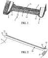
- the Figure 1 illustrates a dashboard 2 according to the invention, hereinafter plate 2.
- the board 2 is intended to be arranged in a passenger compartment of a motor vehicle.
- the board 2 defines a support in, on or through which the equipment of the vehicle is intended to be arranged.
- the board 2 comprises two air vents 4, 6 forming an inlet and / or an air outlet via which the passenger compartment fluidly communicates with the outside of the vehicle and / or with a ventilation equipment of the vehicle .
- the board 2 comprises a cavity 8, a surface 9 intended to be illuminated and a lighting module 10 arranged in the cavity 8.
- the cavity 8 is configured to receive the lighting module 10 in whole or in part.
- the cavity 8 overhangs the surface 9.
- the cavity 8 is open towards the surface 9. In this way, it allows the backlighting of the surface 9 by the lighting module 10, as described in more detail below. after.
- the cavity 8 is delimited laterally by two walls 12 also forming walls of the ventilation orifices 4, 6. In addition, it is delimited in the direction of the depth by a front wall 14 and a rear wall 16 ( Figures 1 and 2 ).
- the front wall 14 is configured to form a masking panel masking the elements of the lighting module 10 located in the cavity for a person located in the passenger compartment.
- the rear wall 16 is configured to form a support on which all or part of the lighting module 10 is fixed.
- the rear wall 16 is further configured to hide equipment of the passenger compartment arranged behind it, such as connection elements.
- the partitions 14 and 16 are for example arranged substantially vertically (in the direction of the orientation of the vehicle). They are for example arranged substantially parallel to each other. In addition, they each extend between the two walls 12. They are for example fixed by their lateral ends to these walls 12.
- the lighting module 10 is configured to illuminate the surface 9. More specifically, the lighting module 10 is advantageously configured to illuminate the surface 9 so that the light rendering obtained is spatially homogeneous over the entire width of the surface 9.
- the lighting module 10 comprises a light source 18 and a light guide 20, hereinafter a guide 20.
- the light source 18 is configured to generate light.
- the light source 18 comprises a photoemissive element (not shown) and a substrate 22 on which the light emitting element is arranged.
- the photoemissive element is for example a light emitting diode configured to generate light when it is supplied with electrical energy.
- the photoemissive element is configured to generate white light.
- the substrate 22 is configured to allow power to the light emitting element electrical energy for the generation of light therefrom.
- the substrate 22 is for example fixed to the rear wall 16.
- the guide 20 is configured to simultaneously guide light within it and to radiate this light towards the surface 9. In particular, it is configured to illuminate the surface 9 homogeneously over the entire width of the surface 9.
- the guide 20 comprises an input portion 24 and an output portion 28.
- the input 24 and output 28 portions are consecutive.
- the input portion 24 is configured to optically couple the light source 18 to the output portion 28.
- the input portion 24 is configured to penetrate the light emitted by the light source 18 within the guide. 20 and to convey at least a portion of this light to the outlet portion 28.
- the input portion 24 is optically coupled to the light source 18 at one of its ends.
- This coupling is for example made in known manner, for example by facing one end of the input portion and the source 18.
- the input portion 24 and the output portion 28 are integral with each other at this end. Alternatively, they are for example fixed to each other.
- the input portion 24 is made from a material configured to allow the propagation of light therein by total internal reflection at the interfaces of the light guide and the external environment.
- the inlet portion 24 is made from polymethyl methacrylate, known as PMMA, or from PC transparent polycarbonate.
- the input portion 24 is not rectilinear. For example, it is curved.
- it has a general elbow shape.
- it comprises a sub-portion that has a general shape of 90 ° elbow, or has such a shape itself.
- This form is adapted to allow a good optical connection of the output portion to the light source while taking into account the space constraints applied to the lighting module 10 and resulting from the presence of the ventilation holes 4, 6 , which proscribe the installation of components of the lighting module 10 within them.
- the input portion 24 comprises a first injection sub-portion 241 and a second connection sub-portion 24C connected optically to each other. They are advantageously material.
- the first sub-portion 241 is configured to optically connect the guide 20 to the light source 18. It has for example a generally cylindrical shape. For example, it has a small longitudinal dimension relative to the longitudinal dimension of the outlet portion 28.
- the second sub-portion 24C is configured to optically connect the first sub-portion 241 to the output portion 28. It is interposed therebetween.
- the second sub-portion 24C has a bent shape.
- this sub-portion has a 90 ° elbow shape.
- these two sub-portions are made from the same material.
- the output portion 28 is configured to simultaneously guide the light that reaches it from the input portion, and to emit at least a portion of this light towards the surface 9. This emission results here from a deviation, or decoupling, of the light propagating therein, as described below.
- the output portion 28 includes one end optically coupled to the input portion 24, and an opposite end. This opposite end is for example free. Alternatively, this end is fixed directly or indirectly to one of the walls 12.
- the output portion 28 is made from a material configured to allow the propagation of light within it and the reflection of the light rays propagating therein at at least a portion of its interfaces with the outside. by total internal reflection.
- the exit portion is made from polymethyl methacrylate, known as PMMA, or from PC transparent polycarbonate.
- the output portion 28 is for example substantially straight.
- the input 24 and output 28 portions have respective optical indices close to each other.
- near optical index is meant that the optical indices are configured so that light passing from one portion to another is not or only slightly deviated.
- the respective optical indices of these portions are substantially identical.
- inlet 24 and outlet 28 portions are integral with each other.
- the portions are not integral with each other and are fixed to one another, for example by gluing or overmolding.
- the output portion 28 is configured to emit light along at least one preferred transmission direction P.
- This direction P is by example inclined at an angle ⁇ relative to the vertical (in the direction of the orientation of the vehicle, which corresponds to that of the Figure 4 ).
- the exit portion 28 includes deflection means 30 configured to deflect at least a portion of the light traveling through the exit portion 28. towards the surface 9.
- the deflection means 30 comprise one or more decoupling elements 32 formed in the surface of the outlet portion 28.
- Each decoupling element also called deflection or decoupling prism, is arranged to decouple out at least a portion of the light incident on this decoupling element.
- they are arranged in an area of this surface which is oriented substantially away from the surface 9. In other words, they are arranged in an area of the surface of the outlet portion 28 opposite the surface 9.
- the decoupling elements 32 are for example in the form of reliefs of chosen shape.
- the decoupling elements 32 are for example arranged projecting with respect to the surface of the portion 28. Alternatively, they are in the form of depressions.
- the decoupling elements 32 have for example a generally toothed shape. Alternatively, they have a general shape of striations, or portions of outer surface torus.
- the decoupling elements 32 are formed along the outlet portion 28.
- the configuration of the decoupling elements, in particular their location within the output portion 28, is chosen so that, together with the final orientation of the output portion 28 within the cavity 8, the light is emitted by the portion in this direction, they are for example formed in the outlet portion at a face thereof opposite the surface 9.
- the deflection means 30 comprise decoupling elements 32 over substantially the entire length of the outlet portion 28.
- each decoupling element of the output portion is arranged to decouple from the light so as to form on the surface 9 respectively an illuminated zone having a given width along the output portion, the decoupling elements being arranged so that the illuminated areas are contiguous and / or overlap each other.
- the guide 20 comprises an optical element 34.
- the optical element 34 is configured to deflect or decouple a portion of the light propagating in the input portion 24 out of the guide and towards the surface 9.
- the optical element is arranged to decouple from the light so as to form on the surface 9 an illuminated zone of greater width than those of the decoupling elements (along the output portion).
- the optical element 34 is arranged at the input portion.
- the optical element 34 is more specifically arranged projecting with respect to the input portion 24. Furthermore, it extends away from the input portion towards the front partition 14.
- the optical element 34 is advantageously configured to emit light in a preferred transmission direction D substantially parallel to the direction P
- the optical element 34 has a general shape of pad. It comprises a base 36, a reflection face 38 and an outlet face 40.
- the base 36 has a portion 37 which forms a proximal end of the element 34 relative to the inlet portion 24.
- This portion 37 is shaped to have a shape complementary to the portion of the surface of the portion of the input at which the optical element 34 is arranged.
- the base 36 has for example a general prismatic shape right or frustoconical.
- the base 36 has a generally frustoconical shape, with the portion 37 conformed.
- the reflection face 38 is in the extension of the base 36. More specifically, the reflection face 38 is formed at the distal end of the base relative to the input portion. The outer surface of the reflection face 38 is oriented away from the surface 9.
- the reflection face 38 is configured to reflect the light entering the optical element 34 in the direction of the exit face 40. In addition, it is configured so that the light beam thus issuing from the optical element 34 illuminates an area Z ( Figure 2 ) of the surface 9 located vertically above the input portion 24 and that the deflection means 30 can not illuminate satisfactorily. In practice, in the absence of the optical element according to the invention, this zone Z is unlit, or at least has an illumination different from that of the rest of the surface 9, thus providing an inhomogeneous apparent result.
- the reflection face 38 is curved.
- the reflection face 38 has the general shape of an outer surface portion of a torus. This geometric configuration has the effect of widening the light beam produced by the element 34 while allowing to obtain a homogeneous light power within this beam. This beam is advantageously centered on the direction D.
- the exit face 40 is opposed to the reflection face 38.
- the exit face 40 corresponds for example to a lower surface of the optical element 34 (in the direction of the orientation of the vehicle), it being understood that this orientation is susceptible to change according to the intended application.
- the exit face 40 is oriented towards the surface 9.
- the exit face 40 is substantially flat.
- the optical element 34 is made of a material adapted for the light to propagate within it by undergoing total internal reflections at its interface with the external environment.
- the optical element 34 advantageously has an optical index close to the optical index of the material of the input portion 24. This promotes the good passage of light between the input portion 24 and the optical element 34 .
- the optical element 34 is made of PMMA or PC.
- optical element 34 is advantageously integral with the input portion 24.
- the optical element 34 is not integral with the input portion. It is then fixed for example.
- the optical element 34 is furthermore arranged on the input portion 24 at a location such that the photons coming from the light source 18 and having penetrated into the light guide 20 can not penetrate into the optical element 34 without having undergone reflection within the guide.
- the optical element 34 is advantageously located at a location such that there is no direct optical path between the end of the input portion 24 coupled to the light source 18 and the optical element 34 .
- the optical element 34 extends from the second sub-portion 24C from a zone of this sub-portion which is closer to the output portion 28 than to the first sub-portion 241 .
- the optical element 34 extends in a direction inclined laterally with respect to a local plane L parallel to an X plane transverse to the output portion 28.
- the optical element 34 extends towards the front partition 14 but is inclined laterally relative to a configuration in which it would extend facing the front partition 14.
- the optical element has a longitudinal dimension of less than 5 mm.
- it is between 1 mm and 5 mm.
- the angle between the axis of the element 34 and the axis of propagation of the light in the outlet portion 28 is advantageously between 45 ° and 90 °.
- the photoemissive element is supplied with electrical energy by the substrate 22, so that the light source 18 emits light. Due to its optical coupling with the input portion 24, at least a portion of the emitted light enters the input portion 24.
- the light propagates in the input portion 24 towards the output portion 28, possibly experiencing one or more total reflections at the interface between the guide 20 and the external environment.
- Part of the light that propagates in the input portion 24 enters the optical element 34. At least a portion of this light then reaches the reflection face 38. It undergoes a reflection and is then deflected in the direction of the exit face 40 that it crosses towards the zone Z of the surface 9. This zone Z then appears on.
- Another part of the light that enters the input portion 24 reaches the output portion 28.
- a portion of the light that reaches the decoupling element is deflected by the decoupling element 32 and is then deflected by the exit portion towards the surface 9.
- Another portion of the light is propagated along the outlet portion 28, so that light reaches each decoupling element and that each decoupling element deflects a portion of the light towards the surface 9.
- the entire light guide 20 is made in one step. This step is for example carried out by molding or by machining.
- injection 24 and output portions 28 and the optical element 34 are made in one piece.
- the elements that come from each other and that come from each other are made in a first step.
- the other element or elements that are not integral with the other elements of the guide material from each other are manufactured in a second step, for example also by molding.
- the different elements are then assembled together, for example by gluing or overmolding.
- the invention has several advantages.
- the presence of the optical element has the effect of allowing extraction of a portion of the light entering the input portion. This makes it possible to compensate for the presence of any dark areas within the light surface, resulting for example from a relative geometrical arrangement of the input portion and the output portion that does not allow the use of conventional deflection means at the input portion for obtaining a satisfactory result.
- optical element itself is relatively simple and inexpensive invoice, so that the overall cost of the guide is only slightly impacted.
- the optical element has small dimensions, so that the size of the light guide is not substantially affected by its presence.
- the absence of a direct optical path between the light source and the optical element has the effect that the light resulting from the presence of the optical element has a high degree of homogeneity with the light deflected by the light source. deviation, until the light from the source 18 only after reflection.
- the light rendering provided on the surface 9 by the lighting module is therefore homogeneous.
Landscapes
- Physics & Mathematics (AREA)
- Engineering & Computer Science (AREA)
- Mechanical Engineering (AREA)
- General Physics & Mathematics (AREA)
- Optics & Photonics (AREA)
- Planar Illumination Modules (AREA)
- Arrangements Of Lighting Devices For Vehicle Interiors, Mounting And Supporting Thereof, Circuits Therefore (AREA)
Applications Claiming Priority (1)
| Application Number | Priority Date | Filing Date | Title |
|---|---|---|---|
| FR1660528A FR3058231B1 (fr) | 2016-10-28 | 2016-10-28 | Guide de lumiere coude ameliore |
Publications (2)
| Publication Number | Publication Date |
|---|---|
| EP3315857A1 true EP3315857A1 (de) | 2018-05-02 |
| EP3315857B1 EP3315857B1 (de) | 2023-06-28 |
Family
ID=57539535
Family Applications (1)
| Application Number | Title | Priority Date | Filing Date |
|---|---|---|---|
| EP17196690.6A Active EP3315857B1 (de) | 2016-10-28 | 2017-10-16 | Verbesserter gebogener lichtwellenleiter |
Country Status (3)
| Country | Link |
|---|---|
| US (1) | US20180118104A1 (de) |
| EP (1) | EP3315857B1 (de) |
| FR (1) | FR3058231B1 (de) |
Families Citing this family (1)
| Publication number | Priority date | Publication date | Assignee | Title |
|---|---|---|---|---|
| DE102019103855B4 (de) | 2019-02-15 | 2021-09-30 | Lisa Dräxlmaier GmbH | Fahrzeuginterieur-Beleuchtungsvorrichtung |
Citations (4)
| Publication number | Priority date | Publication date | Assignee | Title |
|---|---|---|---|---|
| US20010019488A1 (en) * | 1997-12-09 | 2001-09-06 | Hulse George R. | Optical waveguide structures |
| EP2500753A1 (de) * | 2011-03-15 | 2012-09-19 | Automotive Lighting Reutlingen GmbH | Lichtleiter mit direkt Licht auskoppelnden Auskoppelelementen |
| US20150023047A1 (en) * | 2012-05-09 | 2015-01-22 | Yazaki Corporation | Light emitting unit |
| WO2016114336A1 (ja) * | 2015-01-15 | 2016-07-21 | コニカミノルタ株式会社 | 光学素子及び光学素子の製造方法 |
Family Cites Families (6)
| Publication number | Priority date | Publication date | Assignee | Title |
|---|---|---|---|---|
| ITPD20120169A1 (it) * | 2012-05-28 | 2013-11-29 | Automotive Lighting Italia S P A A Socio Unico | Dispositivo di illuminazione per veicoli |
| DE102013108337B4 (de) * | 2013-08-02 | 2022-10-13 | HELLA GmbH & Co. KGaA | Beleuchtungsvorrichtung für Fahrzeuge |
| DE102013226133A1 (de) * | 2013-12-16 | 2015-06-18 | Automotive Lighting Reutlingen Gmbh | Kraftfahrzeugleuchte mit einem Lichtleiter |
| JP2016046120A (ja) * | 2014-08-25 | 2016-04-04 | スタンレー電気株式会社 | 車両用灯具 |
| AT517414A1 (de) * | 2015-06-29 | 2017-01-15 | Zkw Group Gmbh | Lichtleiteranordnung zur Erzeugung von zumindest einer Beleuchtungsfunktion und/oder Signalisierungsfunktion eines Kraftfahrzeugscheinwerfers |
| AT518163B1 (de) * | 2016-02-17 | 2017-08-15 | Zkw Group Gmbh | Lichtleiter für einen Fahrzeugscheinwerfer |
-
2016
- 2016-10-28 FR FR1660528A patent/FR3058231B1/fr active Active
-
2017
- 2017-10-16 EP EP17196690.6A patent/EP3315857B1/de active Active
- 2017-10-26 US US15/794,055 patent/US20180118104A1/en not_active Abandoned
Patent Citations (4)
| Publication number | Priority date | Publication date | Assignee | Title |
|---|---|---|---|---|
| US20010019488A1 (en) * | 1997-12-09 | 2001-09-06 | Hulse George R. | Optical waveguide structures |
| EP2500753A1 (de) * | 2011-03-15 | 2012-09-19 | Automotive Lighting Reutlingen GmbH | Lichtleiter mit direkt Licht auskoppelnden Auskoppelelementen |
| US20150023047A1 (en) * | 2012-05-09 | 2015-01-22 | Yazaki Corporation | Light emitting unit |
| WO2016114336A1 (ja) * | 2015-01-15 | 2016-07-21 | コニカミノルタ株式会社 | 光学素子及び光学素子の製造方法 |
Also Published As
| Publication number | Publication date |
|---|---|
| EP3315857B1 (de) | 2023-06-28 |
| FR3058231B1 (fr) | 2018-12-07 |
| US20180118104A1 (en) | 2018-05-03 |
| FR3058231A1 (fr) | 2018-05-04 |
Similar Documents
| Publication | Publication Date | Title |
|---|---|---|
| EP2865937B1 (de) | Beleuchtungsvorrichtung, die eine Lichtstrahlführung umfasst | |
| FR2966224A1 (fr) | Dispositif d'eclairage ou de signalisation | |
| EP1857732A1 (de) | Vorrichtung zur Beleuchtung und/oder Signalisierung für Kraftfahrzeuge | |
| EP1610158B1 (de) | Signalvorrichtung mit Lichtleiter | |
| EP2666043A1 (de) | Optische einheit für eine signalisierungs- und/oder beleuchtungsvorrichtung | |
| FR2902494A1 (fr) | Dispositif d'eclairage ou de signalisation a guide optique pour vehicule automobile | |
| FR3103877A1 (fr) | Elément optique et module lumineux d’un véhicule automobile équipé d’un tel élément optique | |
| EP2101202A1 (de) | Lichtsignalvorrichtung für Fahrrad | |
| EP3254019A1 (de) | Zum fahren auf der linken seite und zum fahren auf der rechten seite kompatibles fahrzeugleuchtenmodul | |
| FR3032517A1 (fr) | Dispositif lumineux de vehicule | |
| FR3003928A1 (fr) | Dispositif d'eclairage ou de signalisation pour vehicule automobile | |
| FR3064560A1 (fr) | Module d'eclairage interieur pour vehicule automobile | |
| FR3052411A1 (fr) | Element de garnissage comprenant un rideau illumine | |
| EP2216589B1 (de) | Optische Vorrichtung zur Beleuchtung oder Signalisierung, nämlich für ein Kraftfahrzeug | |
| EP3315857B1 (de) | Verbesserter gebogener lichtwellenleiter | |
| EP3024697A1 (de) | Beleuchtungssystem, insbesondere für ein beleuchtungselement eines kraftfahrzeugs mit einer geneigten leiterplatte in relation zur leuchtrichtung | |
| FR3061537B1 (fr) | Module d'emission lumineuse a nappe de guidage ameliore | |
| FR2998644A1 (fr) | Dispositif de signalisation pour vehicule avec effet tridimensionnel | |
| EP2703220B1 (de) | Vorrichtung zur Beleuchtung und/oder Signalisierung für Kraftfahrzeug | |
| EP2302292A1 (de) | Optisches Modul mit Falzmaschine, das aus einem Diopter für transparentes Material/Luft gebildet wird | |
| FR3009065A1 (fr) | Dispositif optique de vehicule automobile | |
| EP3144589B1 (de) | Leuchtvorrichtung, insbesondere für kraftfahrzeug, und scheinwerfer, der eine solche vorrichtung umfasst | |
| EP3303911B1 (de) | Lichtleiter für kraftfahrzeugbeleuchtungs- und/oder signalisierungsvorrichtung | |
| FR3041076A1 (fr) | Module d'eclairage interieur comprenant une fibre optique | |
| FR3133071A1 (fr) | Pièce optique avec plusieurs zones de sortie en série |
Legal Events
| Date | Code | Title | Description |
|---|---|---|---|
| PUAI | Public reference made under article 153(3) epc to a published international application that has entered the european phase |
Free format text: ORIGINAL CODE: 0009012 |
|
| STAA | Information on the status of an ep patent application or granted ep patent |
Free format text: STATUS: THE APPLICATION HAS BEEN PUBLISHED |
|
| AK | Designated contracting states |
Kind code of ref document: A1 Designated state(s): AL AT BE BG CH CY CZ DE DK EE ES FI FR GB GR HR HU IE IS IT LI LT LU LV MC MK MT NL NO PL PT RO RS SE SI SK SM TR |
|
| AX | Request for extension of the european patent |
Extension state: BA ME |
|
| STAA | Information on the status of an ep patent application or granted ep patent |
Free format text: STATUS: REQUEST FOR EXAMINATION WAS MADE |
|
| 17P | Request for examination filed |
Effective date: 20180928 |
|
| RBV | Designated contracting states (corrected) |
Designated state(s): AL AT BE BG CH CY CZ DE DK EE ES FI FR GB GR HR HU IE IS IT LI LT LU LV MC MK MT NL NO PL PT RO RS SE SI SK SM TR |
|
| STAA | Information on the status of an ep patent application or granted ep patent |
Free format text: STATUS: EXAMINATION IS IN PROGRESS |
|
| 17Q | First examination report despatched |
Effective date: 20190219 |
|
| STAA | Information on the status of an ep patent application or granted ep patent |
Free format text: STATUS: EXAMINATION IS IN PROGRESS |
|
| STAA | Information on the status of an ep patent application or granted ep patent |
Free format text: STATUS: EXAMINATION IS IN PROGRESS |
|
| GRAP | Despatch of communication of intention to grant a patent |
Free format text: ORIGINAL CODE: EPIDOSNIGR1 |
|
| STAA | Information on the status of an ep patent application or granted ep patent |
Free format text: STATUS: GRANT OF PATENT IS INTENDED |
|
| INTG | Intention to grant announced |
Effective date: 20230120 |
|
| GRAS | Grant fee paid |
Free format text: ORIGINAL CODE: EPIDOSNIGR3 |
|
| GRAA | (expected) grant |
Free format text: ORIGINAL CODE: 0009210 |
|
| STAA | Information on the status of an ep patent application or granted ep patent |
Free format text: STATUS: THE PATENT HAS BEEN GRANTED |
|
| AK | Designated contracting states |
Kind code of ref document: B1 Designated state(s): AL AT BE BG CH CY CZ DE DK EE ES FI FR GB GR HR HU IE IS IT LI LT LU LV MC MK MT NL NO PL PT RO RS SE SI SK SM TR |
|
| REG | Reference to a national code |
Ref country code: CH Ref legal event code: EP |
|
| P01 | Opt-out of the competence of the unified patent court (upc) registered |
Effective date: 20230528 |
|
| REG | Reference to a national code |
Ref country code: AT Ref legal event code: REF Ref document number: 1582972 Country of ref document: AT Kind code of ref document: T Effective date: 20230715 |
|
| REG | Reference to a national code |
Ref country code: IE Ref legal event code: FG4D Free format text: LANGUAGE OF EP DOCUMENT: FRENCH |
|
| REG | Reference to a national code |
Ref country code: DE Ref legal event code: R096 Ref document number: 602017070613 Country of ref document: DE |
|
| REG | Reference to a national code |
Ref country code: LT Ref legal event code: MG9D |
|
| PG25 | Lapsed in a contracting state [announced via postgrant information from national office to epo] |
Ref country code: SE Free format text: LAPSE BECAUSE OF FAILURE TO SUBMIT A TRANSLATION OF THE DESCRIPTION OR TO PAY THE FEE WITHIN THE PRESCRIBED TIME-LIMIT Effective date: 20230628 Ref country code: NO Free format text: LAPSE BECAUSE OF FAILURE TO SUBMIT A TRANSLATION OF THE DESCRIPTION OR TO PAY THE FEE WITHIN THE PRESCRIBED TIME-LIMIT Effective date: 20230928 |
|
| REG | Reference to a national code |
Ref country code: NL Ref legal event code: MP Effective date: 20230628 |
|
| REG | Reference to a national code |
Ref country code: AT Ref legal event code: MK05 Ref document number: 1582972 Country of ref document: AT Kind code of ref document: T Effective date: 20230628 |
|
| PG25 | Lapsed in a contracting state [announced via postgrant information from national office to epo] |
Ref country code: RS Free format text: LAPSE BECAUSE OF FAILURE TO SUBMIT A TRANSLATION OF THE DESCRIPTION OR TO PAY THE FEE WITHIN THE PRESCRIBED TIME-LIMIT Effective date: 20230628 Ref country code: NL Free format text: LAPSE BECAUSE OF FAILURE TO SUBMIT A TRANSLATION OF THE DESCRIPTION OR TO PAY THE FEE WITHIN THE PRESCRIBED TIME-LIMIT Effective date: 20230628 Ref country code: LV Free format text: LAPSE BECAUSE OF FAILURE TO SUBMIT A TRANSLATION OF THE DESCRIPTION OR TO PAY THE FEE WITHIN THE PRESCRIBED TIME-LIMIT Effective date: 20230628 Ref country code: LT Free format text: LAPSE BECAUSE OF FAILURE TO SUBMIT A TRANSLATION OF THE DESCRIPTION OR TO PAY THE FEE WITHIN THE PRESCRIBED TIME-LIMIT Effective date: 20230628 Ref country code: HR Free format text: LAPSE BECAUSE OF FAILURE TO SUBMIT A TRANSLATION OF THE DESCRIPTION OR TO PAY THE FEE WITHIN THE PRESCRIBED TIME-LIMIT Effective date: 20230628 Ref country code: GR Free format text: LAPSE BECAUSE OF FAILURE TO SUBMIT A TRANSLATION OF THE DESCRIPTION OR TO PAY THE FEE WITHIN THE PRESCRIBED TIME-LIMIT Effective date: 20230929 |
|
| PG25 | Lapsed in a contracting state [announced via postgrant information from national office to epo] |
Ref country code: FI Free format text: LAPSE BECAUSE OF FAILURE TO SUBMIT A TRANSLATION OF THE DESCRIPTION OR TO PAY THE FEE WITHIN THE PRESCRIBED TIME-LIMIT Effective date: 20230628 |
|
| PG25 | Lapsed in a contracting state [announced via postgrant information from national office to epo] |
Ref country code: SK Free format text: LAPSE BECAUSE OF FAILURE TO SUBMIT A TRANSLATION OF THE DESCRIPTION OR TO PAY THE FEE WITHIN THE PRESCRIBED TIME-LIMIT Effective date: 20230628 |
|
| PG25 | Lapsed in a contracting state [announced via postgrant information from national office to epo] |
Ref country code: ES Free format text: LAPSE BECAUSE OF FAILURE TO SUBMIT A TRANSLATION OF THE DESCRIPTION OR TO PAY THE FEE WITHIN THE PRESCRIBED TIME-LIMIT Effective date: 20230628 |
|
| PG25 | Lapsed in a contracting state [announced via postgrant information from national office to epo] |
Ref country code: IS Free format text: LAPSE BECAUSE OF FAILURE TO SUBMIT A TRANSLATION OF THE DESCRIPTION OR TO PAY THE FEE WITHIN THE PRESCRIBED TIME-LIMIT Effective date: 20231028 |
|
| PG25 | Lapsed in a contracting state [announced via postgrant information from national office to epo] |
Ref country code: SM Free format text: LAPSE BECAUSE OF FAILURE TO SUBMIT A TRANSLATION OF THE DESCRIPTION OR TO PAY THE FEE WITHIN THE PRESCRIBED TIME-LIMIT Effective date: 20230628 Ref country code: SK Free format text: LAPSE BECAUSE OF FAILURE TO SUBMIT A TRANSLATION OF THE DESCRIPTION OR TO PAY THE FEE WITHIN THE PRESCRIBED TIME-LIMIT Effective date: 20230628 Ref country code: RO Free format text: LAPSE BECAUSE OF FAILURE TO SUBMIT A TRANSLATION OF THE DESCRIPTION OR TO PAY THE FEE WITHIN THE PRESCRIBED TIME-LIMIT Effective date: 20230628 Ref country code: PT Free format text: LAPSE BECAUSE OF FAILURE TO SUBMIT A TRANSLATION OF THE DESCRIPTION OR TO PAY THE FEE WITHIN THE PRESCRIBED TIME-LIMIT Effective date: 20231030 Ref country code: IS Free format text: LAPSE BECAUSE OF FAILURE TO SUBMIT A TRANSLATION OF THE DESCRIPTION OR TO PAY THE FEE WITHIN THE PRESCRIBED TIME-LIMIT Effective date: 20231028 Ref country code: ES Free format text: LAPSE BECAUSE OF FAILURE TO SUBMIT A TRANSLATION OF THE DESCRIPTION OR TO PAY THE FEE WITHIN THE PRESCRIBED TIME-LIMIT Effective date: 20230628 Ref country code: EE Free format text: LAPSE BECAUSE OF FAILURE TO SUBMIT A TRANSLATION OF THE DESCRIPTION OR TO PAY THE FEE WITHIN THE PRESCRIBED TIME-LIMIT Effective date: 20230628 Ref country code: CZ Free format text: LAPSE BECAUSE OF FAILURE TO SUBMIT A TRANSLATION OF THE DESCRIPTION OR TO PAY THE FEE WITHIN THE PRESCRIBED TIME-LIMIT Effective date: 20230628 Ref country code: AT Free format text: LAPSE BECAUSE OF FAILURE TO SUBMIT A TRANSLATION OF THE DESCRIPTION OR TO PAY THE FEE WITHIN THE PRESCRIBED TIME-LIMIT Effective date: 20230628 |
|
| PGFP | Annual fee paid to national office [announced via postgrant information from national office to epo] |
Ref country code: FR Payment date: 20231023 Year of fee payment: 7 Ref country code: DE Payment date: 20231011 Year of fee payment: 7 |
|
| PG25 | Lapsed in a contracting state [announced via postgrant information from national office to epo] |
Ref country code: PL Free format text: LAPSE BECAUSE OF FAILURE TO SUBMIT A TRANSLATION OF THE DESCRIPTION OR TO PAY THE FEE WITHIN THE PRESCRIBED TIME-LIMIT Effective date: 20230628 |
|
| PG25 | Lapsed in a contracting state [announced via postgrant information from national office to epo] |
Ref country code: DK Free format text: LAPSE BECAUSE OF FAILURE TO SUBMIT A TRANSLATION OF THE DESCRIPTION OR TO PAY THE FEE WITHIN THE PRESCRIBED TIME-LIMIT Effective date: 20230628 |
|
| PLBE | No opposition filed within time limit |
Free format text: ORIGINAL CODE: 0009261 |
|
| STAA | Information on the status of an ep patent application or granted ep patent |
Free format text: STATUS: NO OPPOSITION FILED WITHIN TIME LIMIT |