EP3315811A1 - Elastic member and wire rod for elastic member - Google Patents
Elastic member and wire rod for elastic member Download PDFInfo
- Publication number
- EP3315811A1 EP3315811A1 EP16817914.1A EP16817914A EP3315811A1 EP 3315811 A1 EP3315811 A1 EP 3315811A1 EP 16817914 A EP16817914 A EP 16817914A EP 3315811 A1 EP3315811 A1 EP 3315811A1
- Authority
- EP
- European Patent Office
- Prior art keywords
- elastic member
- alloy
- mpa
- alloy portion
- wire
- Prior art date
- Legal status (The legal status is an assumption and is not a legal conclusion. Google has not performed a legal analysis and makes no representation as to the accuracy of the status listed.)
- Granted
Links
Images



Classifications
-
- F—MECHANICAL ENGINEERING; LIGHTING; HEATING; WEAPONS; BLASTING
- F16—ENGINEERING ELEMENTS AND UNITS; GENERAL MEASURES FOR PRODUCING AND MAINTAINING EFFECTIVE FUNCTIONING OF MACHINES OR INSTALLATIONS; THERMAL INSULATION IN GENERAL
- F16F—SPRINGS; SHOCK-ABSORBERS; MEANS FOR DAMPING VIBRATION
- F16F1/00—Springs
- F16F1/02—Springs made of steel or other material having low internal friction; Wound, torsion, leaf, cup, ring or the like springs, the material of the spring not being relevant
- F16F1/024—Covers or coatings therefor
-
- B—PERFORMING OPERATIONS; TRANSPORTING
- B60—VEHICLES IN GENERAL
- B60G—VEHICLE SUSPENSION ARRANGEMENTS
- B60G11/00—Resilient suspensions characterised by arrangement, location or kind of springs
- B60G11/14—Resilient suspensions characterised by arrangement, location or kind of springs having helical, spiral or coil springs only
-
- B—PERFORMING OPERATIONS; TRANSPORTING
- B60—VEHICLES IN GENERAL
- B60G—VEHICLE SUSPENSION ARRANGEMENTS
- B60G11/00—Resilient suspensions characterised by arrangement, location or kind of springs
- B60G11/18—Resilient suspensions characterised by arrangement, location or kind of springs having torsion-bar springs only
-
- B—PERFORMING OPERATIONS; TRANSPORTING
- B60—VEHICLES IN GENERAL
- B60G—VEHICLE SUSPENSION ARRANGEMENTS
- B60G15/00—Resilient suspensions characterised by arrangement, location or type of combined spring and vibration damper, e.g. telescopic type
- B60G15/02—Resilient suspensions characterised by arrangement, location or type of combined spring and vibration damper, e.g. telescopic type having mechanical spring
- B60G15/06—Resilient suspensions characterised by arrangement, location or type of combined spring and vibration damper, e.g. telescopic type having mechanical spring and fluid damper
- B60G15/067—Resilient suspensions characterised by arrangement, location or type of combined spring and vibration damper, e.g. telescopic type having mechanical spring and fluid damper characterised by the mounting on the vehicle body or chassis of the spring and damper unit
- B60G15/068—Resilient suspensions characterised by arrangement, location or type of combined spring and vibration damper, e.g. telescopic type having mechanical spring and fluid damper characterised by the mounting on the vehicle body or chassis of the spring and damper unit specially adapted for MacPherson strut-type suspension
-
- B—PERFORMING OPERATIONS; TRANSPORTING
- B60—VEHICLES IN GENERAL
- B60G—VEHICLE SUSPENSION ARRANGEMENTS
- B60G21/00—Interconnection systems for two or more resiliently-suspended wheels, e.g. for stabilising a vehicle body with respect to acceleration, deceleration or centrifugal forces
- B60G21/02—Interconnection systems for two or more resiliently-suspended wheels, e.g. for stabilising a vehicle body with respect to acceleration, deceleration or centrifugal forces permanently interconnected
- B60G21/04—Interconnection systems for two or more resiliently-suspended wheels, e.g. for stabilising a vehicle body with respect to acceleration, deceleration or centrifugal forces permanently interconnected mechanically
- B60G21/05—Interconnection systems for two or more resiliently-suspended wheels, e.g. for stabilising a vehicle body with respect to acceleration, deceleration or centrifugal forces permanently interconnected mechanically between wheels on the same axle but on different sides of the vehicle, i.e. the left and right wheel suspensions being interconnected
- B60G21/055—Stabiliser bars
-
- B—PERFORMING OPERATIONS; TRANSPORTING
- B60—VEHICLES IN GENERAL
- B60G—VEHICLE SUSPENSION ARRANGEMENTS
- B60G21/00—Interconnection systems for two or more resiliently-suspended wheels, e.g. for stabilising a vehicle body with respect to acceleration, deceleration or centrifugal forces
- B60G21/02—Interconnection systems for two or more resiliently-suspended wheels, e.g. for stabilising a vehicle body with respect to acceleration, deceleration or centrifugal forces permanently interconnected
- B60G21/04—Interconnection systems for two or more resiliently-suspended wheels, e.g. for stabilising a vehicle body with respect to acceleration, deceleration or centrifugal forces permanently interconnected mechanically
- B60G21/05—Interconnection systems for two or more resiliently-suspended wheels, e.g. for stabilising a vehicle body with respect to acceleration, deceleration or centrifugal forces permanently interconnected mechanically between wheels on the same axle but on different sides of the vehicle, i.e. the left and right wheel suspensions being interconnected
- B60G21/055—Stabiliser bars
- B60G21/0551—Mounting means therefor
-
- C—CHEMISTRY; METALLURGY
- C22—METALLURGY; FERROUS OR NON-FERROUS ALLOYS; TREATMENT OF ALLOYS OR NON-FERROUS METALS
- C22C—ALLOYS
- C22C21/00—Alloys based on aluminium
-
- C—CHEMISTRY; METALLURGY
- C22—METALLURGY; FERROUS OR NON-FERROUS ALLOYS; TREATMENT OF ALLOYS OR NON-FERROUS METALS
- C22C—ALLOYS
- C22C21/00—Alloys based on aluminium
- C22C21/06—Alloys based on aluminium with magnesium as the next major constituent
-
- C—CHEMISTRY; METALLURGY
- C22—METALLURGY; FERROUS OR NON-FERROUS ALLOYS; TREATMENT OF ALLOYS OR NON-FERROUS METALS
- C22C—ALLOYS
- C22C21/00—Alloys based on aluminium
- C22C21/10—Alloys based on aluminium with zinc as the next major constituent
-
- F—MECHANICAL ENGINEERING; LIGHTING; HEATING; WEAPONS; BLASTING
- F16—ENGINEERING ELEMENTS AND UNITS; GENERAL MEASURES FOR PRODUCING AND MAINTAINING EFFECTIVE FUNCTIONING OF MACHINES OR INSTALLATIONS; THERMAL INSULATION IN GENERAL
- F16F—SPRINGS; SHOCK-ABSORBERS; MEANS FOR DAMPING VIBRATION
- F16F1/00—Springs
- F16F1/02—Springs made of steel or other material having low internal friction; Wound, torsion, leaf, cup, ring or the like springs, the material of the spring not being relevant
- F16F1/14—Torsion springs consisting of bars or tubes
-
- B—PERFORMING OPERATIONS; TRANSPORTING
- B60—VEHICLES IN GENERAL
- B60G—VEHICLE SUSPENSION ARRANGEMENTS
- B60G2202/00—Indexing codes relating to the type of spring, damper or actuator
- B60G2202/10—Type of spring
- B60G2202/12—Wound spring
-
- B—PERFORMING OPERATIONS; TRANSPORTING
- B60—VEHICLES IN GENERAL
- B60G—VEHICLE SUSPENSION ARRANGEMENTS
- B60G2202/00—Indexing codes relating to the type of spring, damper or actuator
- B60G2202/10—Type of spring
- B60G2202/13—Torsion spring
- B60G2202/134—Torsion spring comprising a transversal torsion bar and/or tube
-
- B—PERFORMING OPERATIONS; TRANSPORTING
- B60—VEHICLES IN GENERAL
- B60G—VEHICLE SUSPENSION ARRANGEMENTS
- B60G2202/00—Indexing codes relating to the type of spring, damper or actuator
- B60G2202/10—Type of spring
- B60G2202/13—Torsion spring
- B60G2202/135—Stabiliser bar and/or tube
-
- B—PERFORMING OPERATIONS; TRANSPORTING
- B60—VEHICLES IN GENERAL
- B60G—VEHICLE SUSPENSION ARRANGEMENTS
- B60G2204/00—Indexing codes related to suspensions per se or to auxiliary parts
- B60G2204/10—Mounting of suspension elements
- B60G2204/12—Mounting of springs or dampers
- B60G2204/122—Mounting of torsion springs
- B60G2204/1222—Middle mounts of stabiliser on vehicle body or chassis
-
- B—PERFORMING OPERATIONS; TRANSPORTING
- B60—VEHICLES IN GENERAL
- B60G—VEHICLE SUSPENSION ARRANGEMENTS
- B60G2204/00—Indexing codes related to suspensions per se or to auxiliary parts
- B60G2204/10—Mounting of suspension elements
- B60G2204/12—Mounting of springs or dampers
- B60G2204/129—Damper mount on wheel suspension or knuckle
-
- B—PERFORMING OPERATIONS; TRANSPORTING
- B60—VEHICLES IN GENERAL
- B60G—VEHICLE SUSPENSION ARRANGEMENTS
- B60G2206/00—Indexing codes related to the manufacturing of suspensions: constructional features, the materials used, procedures or tools
- B60G2206/01—Constructional features of suspension elements, e.g. arms, dampers, springs
- B60G2206/40—Constructional features of dampers and/or springs
- B60G2206/42—Springs
- B60G2206/426—Coil springs having a particular shape, e.g. curved axis, pig-tail end coils
-
- B—PERFORMING OPERATIONS; TRANSPORTING
- B60—VEHICLES IN GENERAL
- B60G—VEHICLE SUSPENSION ARRANGEMENTS
- B60G2206/00—Indexing codes related to the manufacturing of suspensions: constructional features, the materials used, procedures or tools
- B60G2206/01—Constructional features of suspension elements, e.g. arms, dampers, springs
- B60G2206/40—Constructional features of dampers and/or springs
- B60G2206/42—Springs
- B60G2206/427—Stabiliser bars or tubes
-
- B—PERFORMING OPERATIONS; TRANSPORTING
- B60—VEHICLES IN GENERAL
- B60G—VEHICLE SUSPENSION ARRANGEMENTS
- B60G2206/00—Indexing codes related to the manufacturing of suspensions: constructional features, the materials used, procedures or tools
- B60G2206/01—Constructional features of suspension elements, e.g. arms, dampers, springs
- B60G2206/70—Materials used in suspensions
-
- B—PERFORMING OPERATIONS; TRANSPORTING
- B60—VEHICLES IN GENERAL
- B60G—VEHICLE SUSPENSION ARRANGEMENTS
- B60G2206/00—Indexing codes related to the manufacturing of suspensions: constructional features, the materials used, procedures or tools
- B60G2206/01—Constructional features of suspension elements, e.g. arms, dampers, springs
- B60G2206/70—Materials used in suspensions
- B60G2206/71—Light weight materials
- B60G2206/7102—Aluminium alloys
-
- B—PERFORMING OPERATIONS; TRANSPORTING
- B60—VEHICLES IN GENERAL
- B60G—VEHICLE SUSPENSION ARRANGEMENTS
- B60G2206/00—Indexing codes related to the manufacturing of suspensions: constructional features, the materials used, procedures or tools
- B60G2206/01—Constructional features of suspension elements, e.g. arms, dampers, springs
- B60G2206/70—Materials used in suspensions
- B60G2206/71—Light weight materials
- B60G2206/7103—Magnesium alloys
-
- F—MECHANICAL ENGINEERING; LIGHTING; HEATING; WEAPONS; BLASTING
- F16—ENGINEERING ELEMENTS AND UNITS; GENERAL MEASURES FOR PRODUCING AND MAINTAINING EFFECTIVE FUNCTIONING OF MACHINES OR INSTALLATIONS; THERMAL INSULATION IN GENERAL
- F16F—SPRINGS; SHOCK-ABSORBERS; MEANS FOR DAMPING VIBRATION
- F16F1/00—Springs
- F16F1/02—Springs made of steel or other material having low internal friction; Wound, torsion, leaf, cup, ring or the like springs, the material of the spring not being relevant
- F16F1/021—Springs made of steel or other material having low internal friction; Wound, torsion, leaf, cup, ring or the like springs, the material of the spring not being relevant characterised by their composition, e.g. comprising materials providing for particular spring properties
-
- F—MECHANICAL ENGINEERING; LIGHTING; HEATING; WEAPONS; BLASTING
- F16—ENGINEERING ELEMENTS AND UNITS; GENERAL MEASURES FOR PRODUCING AND MAINTAINING EFFECTIVE FUNCTIONING OF MACHINES OR INSTALLATIONS; THERMAL INSULATION IN GENERAL
- F16F—SPRINGS; SHOCK-ABSORBERS; MEANS FOR DAMPING VIBRATION
- F16F1/00—Springs
- F16F1/02—Springs made of steel or other material having low internal friction; Wound, torsion, leaf, cup, ring or the like springs, the material of the spring not being relevant
- F16F1/04—Wound springs
- F16F1/06—Wound springs with turns lying in cylindrical surfaces
Definitions
- the present invention relates to an elastic member for an automobile, and a wire for the elastic member, the wire being used in manufacture of the elastic member.
- Patent Literature 1 1).
- 7000 series aluminum alloys As aluminum alloys higher in strength than the above mentioned 6000 series aluminum alloys, 7000 series aluminum alloys have been known. If a 7000 series aluminum alloy is used, an elastic member higher in strength than a bolt made of a 6000 series aluminum alloy is able to be made.
- Patent Literature 1 Japanese Patent No. 5335056 Summary
- 7000 series aluminum alloys are generally lower in stress corrosion cracking resistance than 6000 series aluminum alloys, and thus when a 7000 series aluminum alloy is used in an elastic member, its stress corrosion cracking resistance needs to be improved. Under such circumstances, an elastic member made of a material having improved strength and stress corrosion cracking resistance has been demanded.
- the present invention has been made in view of the above, and an object thereof is to provide an elastic member having improved strength and stress corrosion cracking resistance, and a wire for the elastic member, the wire being used in manufacture of the elastic member.
- an elastic member according to the present invention is formed of a wire having a substantially circular cross section orthogonal to a longitudinal direction, expandable and contractible in a predetermined direction and includes: a first alloy portion made of an aluminum alloy having a tensile strength larger than 950 MPa and equal to or less than 1100 MPa at room temperature; and a second alloy portion configured to cover the first alloy portion, the second alloy portion having a thickness in a radial direction smaller than a radius of the first alloy portion, and being made of an aluminum alloy having a tensile strength of 100 MPa to 650 MPa at room temperature.
- the second alloy portion is formed of aluminum alloys being layered over one another, the aluminum alloys having different compositions from one another.
- a radially outermost layer of the second alloy portion is smallest in tensile strength.
- a radially outermost layer of the second alloy portion is smallest in thickness.
- a ratio of the thickness of the second alloy portion to the radius of the first alloy portion is 0.01 to 0.2.
- a wire for an elastic member is a wire having a cross section that is substantially circular, the cross section being orthogonal to a longitudinal direction, and includes: a core portion made of an aluminum alloy having a tensile strength larger than 950 MPa and equal to or less than 1100 MPa at room temperature; and an outer peripheral portion configured to cover the core portion, the outer peripheral portion having a thickness in a radial direction smaller than a radius of the core portion, and being made of an aluminum alloy having a tensile strength of 100 MPa to 650 MPa at room temperature.
- a ratio of the thickness of the outer peripheral portion to the radius of the core portion is 0.01 to 0.2.
- the present invention provides an effect that an elastic member having improved strength and stress corrosion cracking resistance, and a wire for the elastic member, the wire being used in manufacture of the elastic member, are able to be obtained.
- FIG. 1 is a perspective view schematically illustrating a configuration of a suspension according to an embodiment of the present invention.
- a suspension 1 illustrated in FIG. 1 includes: an arm portion 2 that forms a framework of the suspension 1, and rotatably supports two disc rotors 10, to which tires 101 are attached; coil springs 3 (elastic members) that are expandable and contractible in a direction substantially perpendicular to a direction in which the two disc rotors 10 face each other; and shock absorbers 4 that attenuate force (vibration) exerted on expansion and contraction operation of the coil springs 3.
- coil springs 3 elastic members
- shock absorbers 4 that attenuate force (vibration) exerted on expansion and contraction operation of the coil springs 3.
- the disc rotors 10 are each provided with a caliper 11 that is able to decelerate rotation speed of the disc rotor 10 by applying load to the disc rotor 10 in a direction orthogonal to a rotation direction of the disc rotor 10, with the disc rotor 10 inserted in the caliper 11.
- the suspension 1 is installed in a vehicle body 100, and absorbs vibration transmitted from the tires 101 according to irregularities on road surfaces.
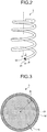
- FIG. 2 is a perspective view schematically illustrating a configuration of main parts of the suspension according to the embodiment of the present invention, and is a perspective view illustrating a configuration of the coil spring 3.
- the coil spring 3 illustrated in FIG. 2 is made of a clad material formed by joining of two types of aluminum (Al) alloys different from each other.
- the coil spring 3 is made by a wire being spirally wound around, the wire being made of the above mentioned clad material and having a cross section that is substantially circular, the cross section being cut along a plane orthogonal to a longitudinal direction thereof.
- the coil spring 3 is expandable and contractible in a predetermined direction (for example, a direction in which the coil spring 3 is stretched by being wound around).
- an aluminum alloy refers to an alloy having aluminum as a main component thereof.
- the coil spring 3 has a first alloy portion 31 and a second alloy portion 32 that are respectively formed by use of two types of aluminum alloys different from each other.
- the first alloy portion 31 forms a portion at a radially inner side of the coil spring 3, and serves as a core portion of the coil spring 3.
- the second alloy portion 32 forms a portion at a radially outer side of the coil spring 3. That is, the second alloy portion 32 forms a surface layer portion of the coil spring 3.
- the first alloy portion 31 is made of an aluminum alloy containing: more than 10.0 wt% and equal to or less than 17.0 wt% of zinc (Zn); and more than 2.0 wt% and equal to or less than 6.0 wt% of magnesium (Mg), with the remainder containing Al and unavoidable impurities.
- the first alloy portion 31 more preferably contains at least one or more types selected from a group consisting of: 0.1 wt% or more and 3.0 wt% or less of copper (Cu); 0.05 wt% or more and 0.4 wt% or less of zirconium (Zr); 0.1 wt% or more and 2.0 wt% or less of manganese (Mn); 0.05 wt% or more and 0.5 wt% or less of iron (Fe); 0.1 wt% or more and 0.6 wt% or less of chromium (Cr); 0.05 wt% or more and 0.4 wt% or less of silicon (Si); 0.01 wt% or more and 0.1 wt% or less of vanadium (V); 0.01 wt% or more and 0.2 wt% or less of titanium (Ti); 0.1 wt% or more and 2.0 wt% or less of nickel (Ni); and 0.01 wt% or more and 0.6 wt% or
- the first alloy portion 31 has a tensile strength larger than 950 MPa and equal to or less than 1100 MPa, at room temperature.
- a tensile strength has a value (for example in MPa) indicating a strength of a material.
- Room temperature referred to herein means temperature that is in a range of, for example, 15°C to 25°C, and that is constant at the time of measurement. The above mentioned tensile strength is obtained because concentrations of Zn and Mg are high, and, in this case, because of occurrence of precipitation hardening due to a precipitate mainly composed of Zn and Mg.
- Zn provides a property of making the tensile strength high, and improving extrusion for when a later described wire for the elastic member (a wire 300 for the elastic member) is manufactured by an extrusion method.
- Mg provides a property of making the tensile strength high.
- Cu provides a property of making the tensile strength high, and improving stress corrosion cracking resistance.
- Zr provides a property of improving toughness, heat resistance, and the stress corrosion cracking resistance.
- Mn provides a property of making the tensile strength high, and improving the toughness, the heat resistance, and the stress corrosion cracking resistance.
- Fe provides a property of improving the heat resistance.
- Cr provides a property of improving the toughness, the heat resistance, and the stress corrosion cracking resistance.
- Ti and Ni provide a property of improving the heat resistance.
- Ag provides a property of making the tensile strength high, and improving the stress corrosion cracking resistance.
- the second alloy portion 32 is made of an aluminum alloy containing 0.005 wt% or more and 6.5 wt% Zn or less of Zn, with the remainder containing Al and unavoidable impurities.
- the second alloy portion 32 has a tensile strength equal to or larger than 100 MPa and equal to or less than 650 MPa, preferably equal to or larger than 350 MPa and equal to or less than 650 MPa, at room temperature.
- a radius of an outer circumference of the second alloy portion 32, that is, a radius of the wire of the coil spring 3 for the suspension 1 is, for example, equal to or larger than 8 mm and equal to or less than 15 mm.
- the second alloy portion 32 preferably contains at least one or more types selected from a group consisting of: 0.05 wt% or more and 2.0 wt% or less of Mg; 0.1 wt% or more and 1.1 wt% or less of Cu; 0.01 wt% or more and 0.25 wt% or less of Zr; 0.051 wt% or more and 1.0 wt% or less of Mn; 0.05 wt% or more and 0.5 wt% or less of Fe; 0.05 wt% or more and 0.3 wt% or less of Cr; 0.05 wt% or more and 1.3 wt% or less of Si; 0.01 wt% or more and 0.1 wt% or less of V; 0.01 wt% or more and 0.2 wt% or less of Ti; 0.1 wt% or more and 2.0 wt% or less of Ni; and 0.01 wt% or more and 0.6 wt% or less of Ag.
- Examples of an aluminum alloy having such a composition include 6000 series aluminum alloys, for example, A6056.
- A6056 is an alloy having Al-Mg-Si as main elements, and is known as an aluminum alloy having a comparatively high tensile strength and having improved stress corrosion cracking resistance.
- a coating may be additionally formed around the second alloy portion 32.
- the coating in this case is formed by use of a material made of, for example, anodized aluminum, and forms a layer having a thickness of about 1/100 of the radius of the outer circumference of the second alloy portion 32. For example, if the dimeter of the outer circumference of the second alloy portion 32 is 10 mm, the thickness of this coating is about 0.1 mm. By the formation of this coating, antirust effect is able to be improved.
- FIG. 3 is a sectional view along a line A-A illustrated in FIG. 2 .
- a cross section illustrated in FIG. 3 is a cross section cut along the plane orthogonal to the longitudinal direction of the wire.
- a relation, "d 2 ⁇ d 1 " is satisfied.
- the radius of the coil spring 3 that is, the radius (d 1 + d 2 ) of the outer circumference of the second alloy portion 32, and the thickness d 2 satisfy a relation, "0.01 ⁇ d 2 /(d 1 + d 2 ) ⁇ 0.2".
- the radius (d 1 + d 2 ) of the outer circumference of the second alloy portion 32 and the thickness d 2 satisfy a relation, "0.05 ⁇ d 2 /(d 1 + d 2 ) ⁇ 0.15".
- FIG. 4 is a sectional view illustrating a configuration of a wire for the elastic member, the wire being a wire for manufacture of the coil spring 3.
- the wire 300 for the elastic member illustrated in this figure (hereinafter, simply referred to as "wire 300") forms a columnar shape having a two-layer structure including: a core portion 301 that is made of the same aluminum alloy as the first alloy portion 31 and that is columnar; and an outer peripheral portion 302 that covers around the core portion 301 and that is made of the same aluminum alloy as the second alloy portion 32.
- the wire 300 is manufactured by, for example, an extrusion method.
- a ratio of a thickness of the outer peripheral portion 302 to a radius of the core portion 301, in the wire 300 is equal to or larger than 0.01 and equal to or less than 0.2.
- the two layer structure including: the first alloy portion 31 that is made of the high strength aluminum alloy serving as the core portion providing springiness of the coil spring 3 and that has the tensile strength larger than 950 MPa and equal to or less than 1100 MPa at room temperature; and the second alloy portion 32 that forms the outer surface, that is made of the aluminum alloy having improved stress corrosion cracking resistance, and that has the tensile strength equal to or larger than 100 MPa and equal to or less than 650 MPa at room temperature; an elastic member having improved strength and stress corrosion cracking resistance is able to be provided.
- the wire 300 for the elastic member being the clad material including: the core portion 301 that serves as the core portion providing the springiness of the coil spring 3 and that is made of the high strength aluminum alloy; and the outer peripheral portion 302 that forms the outer surface and that is made of the aluminum alloy having improved stress corrosion cracking resistance; an elastic member (coil spring 3) having improved strength and stress corrosion cracking resistance is able to be formed by a manufacturing method similar to a conventional manufacturing method.
- FIG. 5 is a sectional view schematically illustrating a configuration of main parts of a suspension according to a modified example of the embodiment of the present invention.
- FIG. 5 is a sectional view of a coil spring 3a according to this modified example, and is a sectional view corresponding to the line A-A in FIG. 2 .
- an alloy portion (second alloy portion 32) made of an aluminum alloy having improved stress corrosion cracking resistance has been described as being provided in one layer on an outer peripheral side of the first alloy portion 31, but the second alloy portion may be formed of two or more layers.
- a second alloy portion made of an aluminum alloy having improved stress corrosion cracking resistance is in two layers, will be described.
- the coil spring 3a illustrated in FIG. 5 is made of a clad material formed by joining of three types of aluminum alloys different from one another.
- the coil spring 3a is made by a wire being spirally wound around, the wire being made of the above described clad material and having a cross section that is substantially circular, the cross section being cut along a plane orthogonal to a longitudinal direction thereof.
- the cross section may have a linearly target shape, such as an elliptical shape, instead of the above described substantially circular shape.
- the coil spring 3a is formed of the first alloy portion 31 and a second alloy portion 33 that are respectively formed by use of three types of aluminum alloys having compositions different from one another.
- the second alloy portion 33 has a first layer 33a provided on the outer peripheral side of the first alloy portion 31, and a second layer 33b that is provided on an outer peripheral side of the first layer 33a and that forms a radially outer portion of the coil spring 3a. That is, the second layer 33b forms a surface layer portion of the coil spring 3a.
- the first layer 33a and the second layer 33b are aluminum alloys that: are formed by combination of types of metals that are the same as those of the metals used in the above described second alloy portion 32, in the same composition range; have tensile strengths in the same range as the second alloy portion 32; and have compositions different from each other. Further, the first layer 33a is equivalent to or larger than the second layer 33b in tensile strength. That is, in a case where the tensile strengths of the first layer 33a and the second layer 33b are different from each other, tensile strength of the coil spring 3a decreases in order from the first alloy portion 31, to the first layer 33a, and then to the second layer 33b.
- a radius of the coil spring 3a that is, a radius (d 1 +d 3 +d 4 ) of an outer circumference of the second alloy portion 33, and a thickness (d 3 +d 4 ) of the second alloy portion 33 satisfy a relation, "0.01 ⁇ (d 3 + d 4 )/(d 1 + d 3 + d 4 ) ⁇ 0.2".
- the radius (d 1 +d 3 +d 4 ) of the outer circumference of the second alloy portion 33 and the thickness (d 3 +d 4 ) satisfy a relation, "0.05 ⁇ (d 3 + d 4 )/(d 1 + d 3 + d 4 ) ⁇ 0.15".
- a layer outermost in the radial direction has the smallest thickness, and the smallest tensile strength.
- the present invention is not to be limited only to the above described embodiment.
- the elastic member according to the present invention maybe realized as another automobile part.
- FIG. 6 is a perspective view schematically illustrating an example of a part, in which the wire for the elastic member according to the embodiment of the present invention is used.
- the coil spring 3 for a suspension has been described as an example, but for example, a stabilizer 5 illustrated in FIG. 6 may be an example.
- the stabilizer 5 is able to be manufactured by the above described wire 300 being bent.
- the stabilizer 5 is bent while expanding and contracting according to load applied thereon (direction in which the load is applied).
- a radius of the outer circumference of the second alloy portion 32 in the stabilizer 5, that is, a dimeter of a wire of the stabilizer 5 is, for example, equal to or larger than 20 mm and equal to or less than 30 mm.
- FIG. 7 is a perspective view schematically illustrating an example of a part, in which the wire for the elastic member according to the embodiment of the present invention is used.
- FIG. 7 is an example of a structure of a suspension of a vehicle.
- a torsion bar 61 is torsionally deformed by receiving rotating force of a trailing link 6 of a suspension 1a illustrated in FIG. 7 .
- Quality of a material of this torsion bar 61 may be realized by use of the above described wire for the elastic member.
- a door impact beam for an automobile may be manufactured by the wire 300 being bent.
- a layer made of an aluminum alloy having improved stress corrosion cracking resistance may be additionally provided on a surface of the second alloy portion 32 or 33.
- a 2000 series, 3000 series, 4000 series, or 5000 series aluminum alloy is an example of such an aluminum alloy.
- the present invention may include various embodiments and the like not described herein, and various design changes and the like within the scope of the technical ideas specified by the scope of the claims may be made.
- an elastic member, and a wire for the elastic member, the wire being used in manufacture of the elastic member, according to the present invention are useful in formation of an elastic member having improved strength and stress corrosion cracking resistance.
Landscapes
- Engineering & Computer Science (AREA)
- Mechanical Engineering (AREA)
- General Engineering & Computer Science (AREA)
- Chemical & Material Sciences (AREA)
- Materials Engineering (AREA)
- Metallurgy (AREA)
- Organic Chemistry (AREA)
- Springs (AREA)
- Vehicle Body Suspensions (AREA)
- Shafts, Cranks, Connecting Bars, And Related Bearings (AREA)
- Laminated Bodies (AREA)
- Ropes Or Cables (AREA)
Abstract
Description
- The present invention relates to an elastic member for an automobile, and a wire for the elastic member, the wire being used in manufacture of the elastic member. Background
- Conventionally, as a method of realizing improvement of fuel efficiency of automobiles, weight reduction of various parts thereof has been pursued. For example, aluminum alloys have started to be used instead of cast iron as a material for engine blocks, and magnesium alloys have started to be used instead of steel as a material for engine covers and oil pans.
- In recent years, in terms of weight reduction of automobiles, use of a material made of an aluminum alloy in an elastic member of, for example, a suspension or the like, has been considered. As such aluminum alloys, 6000 series aluminum alloys have been disclosed (see, for example,
- As aluminum alloys higher in strength than the above mentioned 6000 series aluminum alloys, 7000 series aluminum alloys have been known. If a 7000 series aluminum alloy is used, an elastic member higher in strength than a bolt made of a 6000 series aluminum alloy is able to be made.
- Patent Literature 1: Japanese Patent No.
5335056 - However, 7000 series aluminum alloys are generally lower in stress corrosion cracking resistance than 6000 series aluminum alloys, and thus when a 7000 series aluminum alloy is used in an elastic member, its stress corrosion cracking resistance needs to be improved. Under such circumstances, an elastic member made of a material having improved strength and stress corrosion cracking resistance has been demanded.
- The present invention has been made in view of the above, and an object thereof is to provide an elastic member having improved strength and stress corrosion cracking resistance, and a wire for the elastic member, the wire being used in manufacture of the elastic member. Solution to Problem
- To solve the above-described problem and achieve the object, an elastic member according to the present invention is formed of a wire having a substantially circular cross section orthogonal to a longitudinal direction, expandable and contractible in a predetermined direction and includes: a first alloy portion made of an aluminum alloy having a tensile strength larger than 950 MPa and equal to or less than 1100 MPa at room temperature; and a second alloy portion configured to cover the first alloy portion, the second alloy portion having a thickness in a radial direction smaller than a radius of the first alloy portion, and being made of an aluminum alloy having a tensile strength of 100 MPa to 650 MPa at room temperature.
- Moreover, in the elastic member according to the present invention, the second alloy portion is formed of aluminum alloys being layered over one another, the aluminum alloys having different compositions from one another.
- Moreover, in the elastic member according to the present invention, a radially outermost layer of the second alloy portion is smallest in tensile strength.
- Moreover, in the elastic member according to the present invention, a radially outermost layer of the second alloy portion is smallest in thickness.
- Moreover, in the elastic member according to the present invention, a ratio of the thickness of the second alloy portion to the radius of the first alloy portion is 0.01 to 0.2.
- Moreover, a wire for an elastic member according to the present invention is a wire having a cross section that is substantially circular, the cross section being orthogonal to a longitudinal direction, and includes: a core portion made of an aluminum alloy having a tensile strength larger than 950 MPa and equal to or less than 1100 MPa at room temperature; and an outer peripheral portion configured to cover the core portion, the outer peripheral portion having a thickness in a radial direction smaller than a radius of the core portion, and being made of an aluminum alloy having a tensile strength of 100 MPa to 650 MPa at room temperature.
- Moreover, in the above-described wire for the elastic member according to the present invention, a ratio of the thickness of the outer peripheral portion to the radius of the core portion is 0.01 to 0.2.
- The present invention provides an effect that an elastic member having improved strength and stress corrosion cracking resistance, and a wire for the elastic member, the wire being used in manufacture of the elastic member, are able to be obtained.
-
-
FIG. 1 is a perspective view schematically illustrating a configuration of a suspension according to an embodiment of the present invention. -
FIG. 2 is a perspective view schematically illustrating a configuration of main parts of the suspension according to the embodiment of the present invention. -
FIG. 3 is a sectional view along a line A-A illustrated inFIG. 2 . -
FIG. 4 is a sectional view illustrating a configuration of a wire for the elastic member according to the embodiment of the present invention. -
FIG. 5 is a sectional view schematically illustrating a configuration of main parts of a suspension according to a modified example of the embodiment of the present invention. -
FIG. 6 is a perspective view schematically illustrating an example of a part, in which the wire for the elastic member according to the embodiment of the present invention is used. -
FIG. 7 is a perspective view schematically illustrating an example of a part, in which the wire for the elastic member according to the embodiment of the present invention is used. - Hereinafter, with reference to the appended drawings, a mode for carrying out the present invention (hereinafter, referred to as "embodiment") will be described. The drawings are schematic, a relation between a thickness and a width of each portion and ratios among thicknesses of respective portions may be different from the actual relation and ratios, and the drawings may also include a portion that differs in relations or ratios among its dimensions mutually among the drawings.
-
FIG. 1 is a perspective view schematically illustrating a configuration of a suspension according to an embodiment of the present invention. Asuspension 1 illustrated inFIG. 1 includes: anarm portion 2 that forms a framework of thesuspension 1, and rotatably supports twodisc rotors 10, to whichtires 101 are attached; coil springs 3 (elastic members) that are expandable and contractible in a direction substantially perpendicular to a direction in which the twodisc rotors 10 face each other; and shock absorbers 4 that attenuate force (vibration) exerted on expansion and contraction operation of thecoil springs 3. Thedisc rotors 10 are each provided with acaliper 11 that is able to decelerate rotation speed of thedisc rotor 10 by applying load to thedisc rotor 10 in a direction orthogonal to a rotation direction of thedisc rotor 10, with thedisc rotor 10 inserted in thecaliper 11. Thesuspension 1 is installed in avehicle body 100, and absorbs vibration transmitted from thetires 101 according to irregularities on road surfaces. -
FIG. 2 is a perspective view schematically illustrating a configuration of main parts of the suspension according to the embodiment of the present invention, and is a perspective view illustrating a configuration of thecoil spring 3. Thecoil spring 3 illustrated inFIG. 2 is made of a clad material formed by joining of two types of aluminum (Al) alloys different from each other. Thecoil spring 3 is made by a wire being spirally wound around, the wire being made of the above mentioned clad material and having a cross section that is substantially circular, the cross section being cut along a plane orthogonal to a longitudinal direction thereof. Thecoil spring 3 is expandable and contractible in a predetermined direction (for example, a direction in which thecoil spring 3 is stretched by being wound around). In this specification, an aluminum alloy refers to an alloy having aluminum as a main component thereof. - The
coil spring 3 has afirst alloy portion 31 and asecond alloy portion 32 that are respectively formed by use of two types of aluminum alloys different from each other. Thefirst alloy portion 31 forms a portion at a radially inner side of thecoil spring 3, and serves as a core portion of thecoil spring 3. Thesecond alloy portion 32 forms a portion at a radially outer side of thecoil spring 3. That is, thesecond alloy portion 32 forms a surface layer portion of thecoil spring 3. - The
first alloy portion 31 is made of an aluminum alloy containing: more than 10.0 wt% and equal to or less than 17.0 wt% of zinc (Zn); and more than 2.0 wt% and equal to or less than 6.0 wt% of magnesium (Mg), with the remainder containing Al and unavoidable impurities. Thefirst alloy portion 31 more preferably contains at least one or more types selected from a group consisting of: 0.1 wt% or more and 3.0 wt% or less of copper (Cu); 0.05 wt% or more and 0.4 wt% or less of zirconium (Zr); 0.1 wt% or more and 2.0 wt% or less of manganese (Mn); 0.05 wt% or more and 0.5 wt% or less of iron (Fe); 0.1 wt% or more and 0.6 wt% or less of chromium (Cr); 0.05 wt% or more and 0.4 wt% or less of silicon (Si); 0.01 wt% or more and 0.1 wt% or less of vanadium (V); 0.01 wt% or more and 0.2 wt% or less of titanium (Ti); 0.1 wt% or more and 2.0 wt% or less of nickel (Ni); and 0.01 wt% or more and 0.6 wt% or less of silver (Ag). Thefirst alloy portion 31 has a tensile strength larger than 950 MPa and equal to or less than 1100 MPa, at room temperature. A tensile strength has a value (for example in MPa) indicating a strength of a material. "Room temperature" referred to herein means temperature that is in a range of, for example, 15°C to 25°C, and that is constant at the time of measurement. The above mentioned tensile strength is obtained because concentrations of Zn and Mg are high, and, in this case, because of occurrence of precipitation hardening due to a precipitate mainly composed of Zn and Mg. - Of the metals composing the
first alloy portion 31, Zn provides a property of making the tensile strength high, and improving extrusion for when a later described wire for the elastic member (awire 300 for the elastic member) is manufactured by an extrusion method. Mg provides a property of making the tensile strength high. Cu provides a property of making the tensile strength high, and improving stress corrosion cracking resistance. Zr provides a property of improving toughness, heat resistance, and the stress corrosion cracking resistance. Mn provides a property of making the tensile strength high, and improving the toughness, the heat resistance, and the stress corrosion cracking resistance. Further, Fe provides a property of improving the heat resistance. Cr provides a property of improving the toughness, the heat resistance, and the stress corrosion cracking resistance. Ti and Ni provide a property of improving the heat resistance. Ag provides a property of making the tensile strength high, and improving the stress corrosion cracking resistance. - The
second alloy portion 32 is made of an aluminum alloy containing 0.005 wt% or more and 6.5 wt% Zn or less of Zn, with the remainder containing Al and unavoidable impurities. Thesecond alloy portion 32 has a tensile strength equal to or larger than 100 MPa and equal to or less than 650 MPa, preferably equal to or larger than 350 MPa and equal to or less than 650 MPa, at room temperature. A radius of an outer circumference of thesecond alloy portion 32, that is, a radius of the wire of thecoil spring 3 for thesuspension 1 is, for example, equal to or larger than 8 mm and equal to or less than 15 mm. - The
second alloy portion 32 preferably contains at least one or more types selected from a group consisting of: 0.05 wt% or more and 2.0 wt% or less of Mg; 0.1 wt% or more and 1.1 wt% or less of Cu; 0.01 wt% or more and 0.25 wt% or less of Zr; 0.051 wt% or more and 1.0 wt% or less of Mn; 0.05 wt% or more and 0.5 wt% or less of Fe; 0.05 wt% or more and 0.3 wt% or less of Cr; 0.05 wt% or more and 1.3 wt% or less of Si; 0.01 wt% or more and 0.1 wt% or less of V; 0.01 wt% or more and 0.2 wt% or less of Ti; 0.1 wt% or more and 2.0 wt% or less of Ni; and 0.01 wt% or more and 0.6 wt% or less of Ag. Examples of an aluminum alloy having such a composition include 6000 series aluminum alloys, for example, A6056. A6056 is an alloy having Al-Mg-Si as main elements, and is known as an aluminum alloy having a comparatively high tensile strength and having improved stress corrosion cracking resistance. - A coating may be additionally formed around the
second alloy portion 32. The coating in this case is formed by use of a material made of, for example, anodized aluminum, and forms a layer having a thickness of about 1/100 of the radius of the outer circumference of thesecond alloy portion 32. For example, if the dimeter of the outer circumference of thesecond alloy portion 32 is 10 mm, the thickness of this coating is about 0.1 mm. By the formation of this coating, antirust effect is able to be improved. -
FIG. 3 is a sectional view along a line A-A illustrated inFIG. 2 . A cross section illustrated inFIG. 3 is a cross section cut along the plane orthogonal to the longitudinal direction of the wire. As illustrated inFIG. 3 , when a radius of thefirst alloy portion 31 is d1, and a thickness of thesecond alloy portion 32 in a radial direction thereof is d2; a relation, "d2 < d1", is satisfied. More preferably, the radius of thecoil spring 3, that is, the radius (d1 + d2) of the outer circumference of thesecond alloy portion 32, and the thickness d2 satisfy a relation, "0.01 ≤ d2/(d1 + d2) ≤ 0.2". Even more preferably, the radius (d1 + d2) of the outer circumference of thesecond alloy portion 32 and the thickness d2 satisfy a relation, "0.05 ≤ d2/(d1 + d2) ≤ 0.15". -
FIG. 4 is a sectional view illustrating a configuration of a wire for the elastic member, the wire being a wire for manufacture of thecoil spring 3. Thewire 300 for the elastic member illustrated in this figure (hereinafter, simply referred to as "wire 300") forms a columnar shape having a two-layer structure including: acore portion 301 that is made of the same aluminum alloy as thefirst alloy portion 31 and that is columnar; and an outerperipheral portion 302 that covers around thecore portion 301 and that is made of the same aluminum alloy as thesecond alloy portion 32. Thewire 300 is manufactured by, for example, an extrusion method. Similarly to the above describedfirst alloy portion 31 andsecond alloy portion 32, a ratio of a thickness of the outerperipheral portion 302 to a radius of thecore portion 301, in thewire 300, is equal to or larger than 0.01 and equal to or less than 0.2. By thiswire 300 being wound around, the above describedcoil spring 3 is able to be manufactured. - According to the above described embodiment of the present invention, by formation of the two layer structure including: the
first alloy portion 31 that is made of the high strength aluminum alloy serving as the core portion providing springiness of thecoil spring 3 and that has the tensile strength larger than 950 MPa and equal to or less than 1100 MPa at room temperature; and thesecond alloy portion 32 that forms the outer surface, that is made of the aluminum alloy having improved stress corrosion cracking resistance, and that has the tensile strength equal to or larger than 100 MPa and equal to or less than 650 MPa at room temperature; an elastic member having improved strength and stress corrosion cracking resistance is able to be provided. - Further, according to this embodiment, since the radius (d1 + d2) of the outer circumference of the
second alloy portion 32 and the thickness d2 satisfy the relation, "0.01 ≤ d2/(d1 + d2) ≤ 0.2", strength of thecoil spring 3 is able to be improved, while both this strength and improved stress corrosion cracking resistance are able to be achieved. - Further, according to this embodiment, by formation of the
wire 300 for the elastic member, thewire 300 being the clad material including: thecore portion 301 that serves as the core portion providing the springiness of thecoil spring 3 and that is made of the high strength aluminum alloy; and the outerperipheral portion 302 that forms the outer surface and that is made of the aluminum alloy having improved stress corrosion cracking resistance; an elastic member (coil spring 3) having improved strength and stress corrosion cracking resistance is able to be formed by a manufacturing method similar to a conventional manufacturing method. - Further, according to this embodiment, since the radius (d1+d2) of the outer circumference of the outer
peripheral portion 302 and the thickness (d2) of the outerperipheral portion 302 satisfy the relation, "0.01 ≤ d2/(d1 + d2) ≤ 0.2", strength and stress corrosion cracking resistance of the elastic member that has been formed are able to be achieved with appropriate balance therebetween. -
FIG. 5 is a sectional view schematically illustrating a configuration of main parts of a suspension according to a modified example of the embodiment of the present invention.FIG. 5 is a sectional view of acoil spring 3a according to this modified example, and is a sectional view corresponding to the line A-A inFIG. 2 . In the above described embodiment, an alloy portion (second alloy portion 32) made of an aluminum alloy having improved stress corrosion cracking resistance has been described as being provided in one layer on an outer peripheral side of thefirst alloy portion 31, but the second alloy portion may be formed of two or more layers. In this modified example, an example, in which a second alloy portion made of an aluminum alloy having improved stress corrosion cracking resistance is in two layers, will be described. - The
coil spring 3a illustrated inFIG. 5 is made of a clad material formed by joining of three types of aluminum alloys different from one another. Thecoil spring 3a is made by a wire being spirally wound around, the wire being made of the above described clad material and having a cross section that is substantially circular, the cross section being cut along a plane orthogonal to a longitudinal direction thereof. The cross section may have a linearly target shape, such as an elliptical shape, instead of the above described substantially circular shape. - The
coil spring 3a is formed of thefirst alloy portion 31 and asecond alloy portion 33 that are respectively formed by use of three types of aluminum alloys having compositions different from one another. Thesecond alloy portion 33 has afirst layer 33a provided on the outer peripheral side of thefirst alloy portion 31, and asecond layer 33b that is provided on an outer peripheral side of thefirst layer 33a and that forms a radially outer portion of thecoil spring 3a. That is, thesecond layer 33b forms a surface layer portion of thecoil spring 3a. - The
first layer 33a and thesecond layer 33b are aluminum alloys that: are formed by combination of types of metals that are the same as those of the metals used in the above describedsecond alloy portion 32, in the same composition range; have tensile strengths in the same range as thesecond alloy portion 32; and have compositions different from each other. Further, thefirst layer 33a is equivalent to or larger than thesecond layer 33b in tensile strength. That is, in a case where the tensile strengths of thefirst layer 33a and thesecond layer 33b are different from each other, tensile strength of thecoil spring 3a decreases in order from thefirst alloy portion 31, to thefirst layer 33a, and then to thesecond layer 33b. - As illustrated in
FIG. 5 , when a radius of thefirst alloy portion 31 is d1, a thickness of thefirst layer 33a of thesecond alloy portion 33 in a radial direction thereof is d3, and a thickness of thesecond layer 33b thereof in the radial direction is d4; a relation, "d4 ≤ d3 < d1", is satisfied. More preferably, a radius of thecoil spring 3a, that is, a radius (d1+d3+d4) of an outer circumference of thesecond alloy portion 33, and a thickness (d3+d4) of thesecond alloy portion 33 satisfy a relation, "0.01 ≤ (d3 + d4)/(d1 + d3 + d4) ≤ 0.2". Even more preferably, the radius (d1+d3+d4) of the outer circumference of thesecond alloy portion 33 and the thickness (d3+d4) satisfy a relation, "0.05 ≤ (d3 + d4)/(d 1+ d3 + d4) ≤ 0.15". - According to this modified example, by adopting a three-layer structure including: the
first alloy portion 31 that serves as the core portion providing the springiness of thecoil spring 3a and that is made of a high strength aluminum alloy; and thesecond alloy portion 33 that has the two-layer structure made of aluminum alloys having improved stress corrosion cracking resistance; an elastic member having improved strength and stress corrosion cracking resistance is able to be provided. - Further, according to this modified example, since the radius (d1+d3+d4) of the outer circumference of the
second alloy portion 33 and the thickness (d3+d4) of thesecond alloy portion 33 satisfy the relation, "0.01 ≤ (d3 + d4)/(d1 + d3 + d4) ≤ 0.2", strength of thecoil spring 3a is able to be improved, while both this strength and improved stress corrosion cracking resistance are able to be achieved. - In this modified example, in a case where the second alloy portion has three layers or more, a layer outermost in the radial direction has the smallest thickness, and the smallest tensile strength.
- Thus far, modes for carrying out the present invention have been described, but the present invention is not to be limited only to the above described embodiment. For example, the elastic member according to the present invention maybe realized as another automobile part.
-
FIG. 6 is a perspective view schematically illustrating an example of a part, in which the wire for the elastic member according to the embodiment of the present invention is used. In the embodiment, thecoil spring 3 for a suspension has been described as an example, but for example, astabilizer 5 illustrated inFIG. 6 may be an example. Thestabilizer 5 is able to be manufactured by the above describedwire 300 being bent. Thestabilizer 5 is bent while expanding and contracting according to load applied thereon (direction in which the load is applied). A radius of the outer circumference of thesecond alloy portion 32 in thestabilizer 5, that is, a dimeter of a wire of thestabilizer 5 is, for example, equal to or larger than 20 mm and equal to or less than 30 mm. -
FIG. 7 is a perspective view schematically illustrating an example of a part, in which the wire for the elastic member according to the embodiment of the present invention is used.FIG. 7 is an example of a structure of a suspension of a vehicle. Atorsion bar 61 is torsionally deformed by receiving rotating force of a trailing link 6 of asuspension 1a illustrated inFIG. 7 . Quality of a material of thistorsion bar 61 may be realized by use of the above described wire for the elastic member. In addition, a door impact beam for an automobile may be manufactured by thewire 300 being bent. - Further, in the present invention, a layer made of an aluminum alloy having improved stress corrosion cracking resistance may be additionally provided on a surface of the
second alloy portion - Accordingly, the present invention may include various embodiments and the like not described herein, and various design changes and the like within the scope of the technical ideas specified by the scope of the claims may be made.
- As described above, an elastic member, and a wire for the elastic member, the wire being used in manufacture of the elastic member, according to the present invention, are useful in formation of an elastic member having improved strength and stress corrosion cracking resistance. Reference Signs List
-
- 1
- SUSPENSION
- 2
- ARM PORTION
- 3, 3a
- COIL SPRING
- 4
- SHOCK ABSORBER
- 5
- STABILIZER
- 10
- DISC ROTOR
- 11
- CALIPER
- 31
- FIRST ALLOY PORTION
- 32, 33
- SECOND ALLOY PORTION
- 33a
- FIRST LAYER
- 33b
- SECOND LAYER
- 100
- VEHICLE BODY
- 101
- TIRE
Claims (7)
- An elastic member formed of a wire having a substantially circular cross section orthogonal to a longitudinal direction, the elastic member being expandable and contractible in a predetermined direction and comprising:a first alloy portion made of an aluminum alloy having a tensile strength larger than 950 MPa and equal to or less than 1100 MPa at room temperature; anda second alloy portion configured to cover the first alloy portion, the second alloy portion having a thickness in a radial direction smaller than a radius of the first alloy portion, and being made of an aluminum alloy having a tensile strength of 100 MPa to 650 MPa at room temperature.
- The elastic member according to claim 1, wherein the second alloy portion is formed of aluminum alloys being layered over one another, the aluminum alloys having different compositions from one another.
- The elastic member according to claim 2, wherein a radially outermost layer of the second alloy portion is smallest in tensile strength.
- The elastic member according to claim 2 or 3, wherein a radially outermost layer of the second alloy portion is smallest in thickness.
- The elastic member according to any one of claims 1 to 4, wherein a ratio of the thickness of the second alloy portion to the radius of the first alloy portion is 0.01 to 0.2.
- A wire for an elastic member, the wire having a cross section that is substantially circular, the cross section being orthogonal to a longitudinal direction, the wire comprising:a core portion made of an aluminum alloy having a tensile strength larger than 950 MPa and equal to or less than 1100 MPa at room temperature; andan outer peripheral portion configured to cover the core portion, the outer peripheral portion having a thickness in a radial direction smaller than a radius of the core portion, and being made of an aluminum alloy having a tensile strength of 100 MPa to 650 MPa at room temperature.
- The wire for the elastic member according to claim 6, wherein a ratio of the thickness of the outer peripheral portion to the radius of the core portion is 0.01 to 0.2.
Applications Claiming Priority (2)
| Application Number | Priority Date | Filing Date | Title |
|---|---|---|---|
| JP2015130303 | 2015-06-29 | ||
| PCT/JP2016/069142 WO2017002806A1 (en) | 2015-06-29 | 2016-06-28 | Elastic member and wire rod for elastic member |
Publications (3)
| Publication Number | Publication Date |
|---|---|
| EP3315811A1 true EP3315811A1 (en) | 2018-05-02 |
| EP3315811A4 EP3315811A4 (en) | 2019-03-13 |
| EP3315811B1 EP3315811B1 (en) | 2019-11-06 |
Family
ID=57609566
Family Applications (1)
| Application Number | Title | Priority Date | Filing Date |
|---|---|---|---|
| EP16817914.1A Active EP3315811B1 (en) | 2015-06-29 | 2016-06-28 | Elastic member and wire rod for elastic member |
Country Status (8)
| Country | Link |
|---|---|
| US (2) | US10591011B2 (en) |
| EP (1) | EP3315811B1 (en) |
| JP (1) | JP6634448B2 (en) |
| CN (2) | CN107949719B (en) |
| BR (1) | BR112017028367A2 (en) |
| ES (1) | ES2761673T3 (en) |
| MX (1) | MX386876B (en) |
| WO (1) | WO2017002806A1 (en) |
Families Citing this family (2)
| Publication number | Priority date | Publication date | Assignee | Title |
|---|---|---|---|---|
| JP6634448B2 (en) * | 2015-06-29 | 2020-01-22 | 日本発條株式会社 | Elastic member and wire for elastic member |
| CN111299476B (en) * | 2019-12-23 | 2022-04-15 | 太仓市惠得利弹簧有限公司 | Metal fatigue resistant spring steel wire processing technology |
Family Cites Families (22)
| Publication number | Priority date | Publication date | Assignee | Title |
|---|---|---|---|---|
| US4079926A (en) * | 1976-01-05 | 1978-03-21 | Brunswick Corporation | Energy absorbing support |
| JPS59205105A (en) * | 1983-05-07 | 1984-11-20 | 住友電気工業株式会社 | Conductive composite material |
| FR2716896B1 (en) * | 1994-03-02 | 1996-04-26 | Pechiney Recherche | Alloy 7000 with high mechanical resistance and process for obtaining it. |
| JPH10196697A (en) * | 1997-01-10 | 1998-07-31 | Kobe Steel Ltd | High strength spring with excellent environmental brittleness resistance |
| JPH11230221A (en) | 1998-02-19 | 1999-08-27 | Ihara Kogyo Kk | Coil spring |
| FR2788317B1 (en) | 1999-01-13 | 2002-02-15 | Pechiney Rhenalu | HELICOIDAL SPRING IN ALUMINUM ALLOY WIRE |
| JP2000328209A (en) | 1999-05-18 | 2000-11-28 | Furukawa Electric Co Ltd:The | Manufacturing method of aluminum alloy spring material |
| JP3851095B2 (en) * | 2001-02-07 | 2006-11-29 | 新日本製鐵株式会社 | Heat-treated steel wire for high-strength springs |
| JP2004353080A (en) | 2003-05-02 | 2004-12-16 | Mitsubishi Alum Co Ltd | Aluminum alloy sheet for cap, and its production method |
| US9293849B2 (en) * | 2008-07-30 | 2016-03-22 | Bal Seal Engineering, Inc. | Electrical connector using a canted coil multi-metallic wire |
| US20100289198A1 (en) * | 2009-04-28 | 2010-11-18 | Pete Balsells | Multilayered canted coil springs and associated methods |
| CN101608678A (en) * | 2009-07-15 | 2009-12-23 | 环麒钢铝合金股份有限公司 | Aluminum alloy shock absorbing spring and method for manufacturing the same |
| DE102010053732A1 (en) * | 2010-10-25 | 2012-04-26 | Daimler Ag | Torsion bar or roll stabilizer for a motor vehicle and method for its production |
| JP5782298B2 (en) | 2011-05-31 | 2015-09-24 | 住友電気工業株式会社 | Oblique winding spring and wire for oblique winding spring |
| JP5388157B2 (en) * | 2011-11-02 | 2014-01-15 | 株式会社Uacj | Aluminum alloy clad material for forming |
| JP5335056B2 (en) * | 2011-11-16 | 2013-11-06 | 住友電気工業株式会社 | Aluminum alloy wire for bolt, bolt and method for producing the same |
| CN102888526A (en) * | 2012-09-17 | 2013-01-23 | 镇江忆诺唯记忆合金有限公司 | High-alumina low-manganese CuAlMn low-temperature memory alloy spring |
| JP5968285B2 (en) * | 2013-09-09 | 2016-08-10 | 株式会社神戸製鋼所 | Bumper reinforcement and manufacturing method thereof |
| CN203500346U (en) * | 2013-09-23 | 2014-03-26 | 浙江伊思灵双第弹簧有限公司 | Improved spring |
| CN106164504B (en) | 2014-03-20 | 2019-05-28 | 日本发条株式会社 | Fastening parts and rod-shaped parts for fastening parts |
| CN203979232U (en) | 2014-07-23 | 2014-12-03 | 温州天力弹簧有限公司 | Power spring |
| JP6634448B2 (en) * | 2015-06-29 | 2020-01-22 | 日本発條株式会社 | Elastic member and wire for elastic member |
-
2016
- 2016-06-28 JP JP2017526369A patent/JP6634448B2/en active Active
- 2016-06-28 MX MX2018000017A patent/MX386876B/en unknown
- 2016-06-28 EP EP16817914.1A patent/EP3315811B1/en active Active
- 2016-06-28 WO PCT/JP2016/069142 patent/WO2017002806A1/en not_active Ceased
- 2016-06-28 US US15/740,634 patent/US10591011B2/en active Active
- 2016-06-28 ES ES16817914T patent/ES2761673T3/en active Active
- 2016-06-28 BR BR112017028367-0A patent/BR112017028367A2/en active Search and Examination
- 2016-06-28 CN CN201680037944.3A patent/CN107949719B/en active Active
- 2016-06-28 CN CN202010042067.7A patent/CN111156271B/en active Active
-
2020
- 2020-02-03 US US16/779,799 patent/US11028893B2/en active Active
Also Published As
| Publication number | Publication date |
|---|---|
| JPWO2017002806A1 (en) | 2018-06-07 |
| CN111156271B (en) | 2022-04-19 |
| ES2761673T3 (en) | 2020-05-20 |
| US10591011B2 (en) | 2020-03-17 |
| JP6634448B2 (en) | 2020-01-22 |
| CN111156271A (en) | 2020-05-15 |
| BR112017028367A2 (en) | 2019-02-12 |
| CN107949719B (en) | 2020-02-18 |
| CN107949719A (en) | 2018-04-20 |
| MX2018000017A (en) | 2019-01-31 |
| MX386876B (en) | 2025-03-19 |
| EP3315811A4 (en) | 2019-03-13 |
| US20200173510A1 (en) | 2020-06-04 |
| WO2017002806A1 (en) | 2017-01-05 |
| US20180180126A1 (en) | 2018-06-28 |
| EP3315811B1 (en) | 2019-11-06 |
| US11028893B2 (en) | 2021-06-08 |
Similar Documents
| Publication | Publication Date | Title |
|---|---|---|
| US10494701B2 (en) | Composite material for a sliding bearing | |
| EP1255056A2 (en) | Stabilizer bar | |
| US11028893B2 (en) | Elastic member and wire for elastic member | |
| US20040070129A1 (en) | Force connection strut | |
| US9789532B2 (en) | Suspension arm for motor vehicle and method of manufacture thereof | |
| CN105378124B (en) | Tinbase antifriction metal | |
| JP2015528856A (en) | Improved 6xxx aluminum alloy and method for producing the same | |
| EP2326517A1 (en) | Rim for a motor vehicle | |
| GB2268188A (en) | Bearings | |
| CN111511941B (en) | Aluminum alloy, aluminum alloy spring, and aluminum alloy fastening member | |
| CN101180472A (en) | Plain bearing composite, use of a plain bearing composite, and method for manufacturing a plain bearing composite | |
| CN109414751B (en) | Wheel and use | |
| DE102011076453A1 (en) | Piston ring with composite coating | |
| CN102094925B (en) | Shaft spring of railway vehicle | |
| US20150330567A1 (en) | Component comprising a metal matrix reinforcement member and method of formation thereof | |
| EP3343049B1 (en) | Fastening member and rod-shaped member for fastening members | |
| GB2491798A (en) | Aluminum alloy bearing | |
| US20150322556A1 (en) | Lithium free elevated temperature aluminum copper magnesium silver alloy for forged aerospace products | |
| US11312175B2 (en) | Automobile hub of multilayer rim, hub assembling method and automobile | |
| JPS58197258A (en) | Car part suffering from big bending stress | |
| JP2019517389A (en) | Method for producing parts composed at least partially of metal alloys, and optimization method | |
| DE102010010145A1 (en) | Brake disk for disk brake of motor vehicle, has axial stepped offset circumferentially surrounding central through hole of face surface of brake-disk chamber, and friction ring formed from aluminum-based metal matrix composite material | |
| CN211343584U (en) | Embedded combined cylinder structure of prestressing force | |
| JP6964552B2 (en) | Aluminum alloy and clad material made of aluminum alloy | |
| KR20230022980A (en) | Helical compression spring with non-circular cross-section for actuators to open and close automobile doors or tailgates |
Legal Events
| Date | Code | Title | Description |
|---|---|---|---|
| STAA | Information on the status of an ep patent application or granted ep patent |
Free format text: STATUS: THE INTERNATIONAL PUBLICATION HAS BEEN MADE |
|
| PUAI | Public reference made under article 153(3) epc to a published international application that has entered the european phase |
Free format text: ORIGINAL CODE: 0009012 |
|
| STAA | Information on the status of an ep patent application or granted ep patent |
Free format text: STATUS: REQUEST FOR EXAMINATION WAS MADE |
|
| 17P | Request for examination filed |
Effective date: 20180122 |
|
| AK | Designated contracting states |
Kind code of ref document: A1 Designated state(s): AL AT BE BG CH CY CZ DE DK EE ES FI FR GB GR HR HU IE IS IT LI LT LU LV MC MK MT NL NO PL PT RO RS SE SI SK SM TR |
|
| AX | Request for extension of the european patent |
Extension state: BA ME |
|
| DAV | Request for validation of the european patent (deleted) | ||
| DAX | Request for extension of the european patent (deleted) | ||
| A4 | Supplementary search report drawn up and despatched |
Effective date: 20190213 |
|
| RIC1 | Information provided on ipc code assigned before grant |
Ipc: F16F 1/02 20060101AFI20190207BHEP Ipc: F16F 1/06 20060101ALI20190207BHEP Ipc: F16F 1/14 20060101ALI20190207BHEP Ipc: C22C 21/00 20060101ALI20190207BHEP |
|
| GRAP | Despatch of communication of intention to grant a patent |
Free format text: ORIGINAL CODE: EPIDOSNIGR1 |
|
| STAA | Information on the status of an ep patent application or granted ep patent |
Free format text: STATUS: GRANT OF PATENT IS INTENDED |
|
| INTG | Intention to grant announced |
Effective date: 20190701 |
|
| RIN1 | Information on inventor provided before grant (corrected) |
Inventor name: ISHIKAWA, SHIGEKI Inventor name: TAKAMURA, NORITOSHI Inventor name: KAZAMA, TOSHIO Inventor name: SUZUKI, TAKESHI |
|
| GRAS | Grant fee paid |
Free format text: ORIGINAL CODE: EPIDOSNIGR3 |
|
| GRAA | (expected) grant |
Free format text: ORIGINAL CODE: 0009210 |
|
| STAA | Information on the status of an ep patent application or granted ep patent |
Free format text: STATUS: THE PATENT HAS BEEN GRANTED |
|
| AK | Designated contracting states |
Kind code of ref document: B1 Designated state(s): AL AT BE BG CH CY CZ DE DK EE ES FI FR GB GR HR HU IE IS IT LI LT LU LV MC MK MT NL NO PL PT RO RS SE SI SK SM TR |
|
| REG | Reference to a national code |
Ref country code: GB Ref legal event code: FG4D |
|
| REG | Reference to a national code |
Ref country code: CH Ref legal event code: EP Ref country code: AT Ref legal event code: REF Ref document number: 1199127 Country of ref document: AT Kind code of ref document: T Effective date: 20191115 |
|
| REG | Reference to a national code |
Ref country code: IE Ref legal event code: FG4D |
|
| REG | Reference to a national code |
Ref country code: DE Ref legal event code: R096 Ref document number: 602016024000 Country of ref document: DE |
|
| REG | Reference to a national code |
Ref country code: SE Ref legal event code: TRGR |
|
| REG | Reference to a national code |
Ref country code: NL Ref legal event code: MP Effective date: 20191106 |
|
| REG | Reference to a national code |
Ref country code: LT Ref legal event code: MG4D |
|
| PG25 | Lapsed in a contracting state [announced via postgrant information from national office to epo] |
Ref country code: PT Free format text: LAPSE BECAUSE OF FAILURE TO SUBMIT A TRANSLATION OF THE DESCRIPTION OR TO PAY THE FEE WITHIN THE PRESCRIBED TIME-LIMIT Effective date: 20200306 Ref country code: LV Free format text: LAPSE BECAUSE OF FAILURE TO SUBMIT A TRANSLATION OF THE DESCRIPTION OR TO PAY THE FEE WITHIN THE PRESCRIBED TIME-LIMIT Effective date: 20191106 Ref country code: NO Free format text: LAPSE BECAUSE OF FAILURE TO SUBMIT A TRANSLATION OF THE DESCRIPTION OR TO PAY THE FEE WITHIN THE PRESCRIBED TIME-LIMIT Effective date: 20200206 Ref country code: GR Free format text: LAPSE BECAUSE OF FAILURE TO SUBMIT A TRANSLATION OF THE DESCRIPTION OR TO PAY THE FEE WITHIN THE PRESCRIBED TIME-LIMIT Effective date: 20200207 Ref country code: BG Free format text: LAPSE BECAUSE OF FAILURE TO SUBMIT A TRANSLATION OF THE DESCRIPTION OR TO PAY THE FEE WITHIN THE PRESCRIBED TIME-LIMIT Effective date: 20200206 Ref country code: PL Free format text: LAPSE BECAUSE OF FAILURE TO SUBMIT A TRANSLATION OF THE DESCRIPTION OR TO PAY THE FEE WITHIN THE PRESCRIBED TIME-LIMIT Effective date: 20191106 Ref country code: FI Free format text: LAPSE BECAUSE OF FAILURE TO SUBMIT A TRANSLATION OF THE DESCRIPTION OR TO PAY THE FEE WITHIN THE PRESCRIBED TIME-LIMIT Effective date: 20191106 Ref country code: LT Free format text: LAPSE BECAUSE OF FAILURE TO SUBMIT A TRANSLATION OF THE DESCRIPTION OR TO PAY THE FEE WITHIN THE PRESCRIBED TIME-LIMIT Effective date: 20191106 Ref country code: NL Free format text: LAPSE BECAUSE OF FAILURE TO SUBMIT A TRANSLATION OF THE DESCRIPTION OR TO PAY THE FEE WITHIN THE PRESCRIBED TIME-LIMIT Effective date: 20191106 |
|
| REG | Reference to a national code |
Ref country code: ES Ref legal event code: FG2A Ref document number: 2761673 Country of ref document: ES Kind code of ref document: T3 Effective date: 20200520 |
|
| PG25 | Lapsed in a contracting state [announced via postgrant information from national office to epo] |
Ref country code: HR Free format text: LAPSE BECAUSE OF FAILURE TO SUBMIT A TRANSLATION OF THE DESCRIPTION OR TO PAY THE FEE WITHIN THE PRESCRIBED TIME-LIMIT Effective date: 20191106 Ref country code: IS Free format text: LAPSE BECAUSE OF FAILURE TO SUBMIT A TRANSLATION OF THE DESCRIPTION OR TO PAY THE FEE WITHIN THE PRESCRIBED TIME-LIMIT Effective date: 20200306 Ref country code: RS Free format text: LAPSE BECAUSE OF FAILURE TO SUBMIT A TRANSLATION OF THE DESCRIPTION OR TO PAY THE FEE WITHIN THE PRESCRIBED TIME-LIMIT Effective date: 20191106 |
|
| PG25 | Lapsed in a contracting state [announced via postgrant information from national office to epo] |
Ref country code: AL Free format text: LAPSE BECAUSE OF FAILURE TO SUBMIT A TRANSLATION OF THE DESCRIPTION OR TO PAY THE FEE WITHIN THE PRESCRIBED TIME-LIMIT Effective date: 20191106 |
|
| PG25 | Lapsed in a contracting state [announced via postgrant information from national office to epo] |
Ref country code: RO Free format text: LAPSE BECAUSE OF FAILURE TO SUBMIT A TRANSLATION OF THE DESCRIPTION OR TO PAY THE FEE WITHIN THE PRESCRIBED TIME-LIMIT Effective date: 20191106 Ref country code: CZ Free format text: LAPSE BECAUSE OF FAILURE TO SUBMIT A TRANSLATION OF THE DESCRIPTION OR TO PAY THE FEE WITHIN THE PRESCRIBED TIME-LIMIT Effective date: 20191106 Ref country code: DK Free format text: LAPSE BECAUSE OF FAILURE TO SUBMIT A TRANSLATION OF THE DESCRIPTION OR TO PAY THE FEE WITHIN THE PRESCRIBED TIME-LIMIT Effective date: 20191106 Ref country code: EE Free format text: LAPSE BECAUSE OF FAILURE TO SUBMIT A TRANSLATION OF THE DESCRIPTION OR TO PAY THE FEE WITHIN THE PRESCRIBED TIME-LIMIT Effective date: 20191106 |
|
| REG | Reference to a national code |
Ref country code: DE Ref legal event code: R097 Ref document number: 602016024000 Country of ref document: DE |
|
| REG | Reference to a national code |
Ref country code: AT Ref legal event code: MK05 Ref document number: 1199127 Country of ref document: AT Kind code of ref document: T Effective date: 20191106 |
|
| PG25 | Lapsed in a contracting state [announced via postgrant information from national office to epo] |
Ref country code: SM Free format text: LAPSE BECAUSE OF FAILURE TO SUBMIT A TRANSLATION OF THE DESCRIPTION OR TO PAY THE FEE WITHIN THE PRESCRIBED TIME-LIMIT Effective date: 20191106 Ref country code: SK Free format text: LAPSE BECAUSE OF FAILURE TO SUBMIT A TRANSLATION OF THE DESCRIPTION OR TO PAY THE FEE WITHIN THE PRESCRIBED TIME-LIMIT Effective date: 20191106 |
|
| PLBE | No opposition filed within time limit |
Free format text: ORIGINAL CODE: 0009261 |
|
| STAA | Information on the status of an ep patent application or granted ep patent |
Free format text: STATUS: NO OPPOSITION FILED WITHIN TIME LIMIT |
|
| 26N | No opposition filed |
Effective date: 20200807 |
|
| PG25 | Lapsed in a contracting state [announced via postgrant information from national office to epo] |
Ref country code: AT Free format text: LAPSE BECAUSE OF FAILURE TO SUBMIT A TRANSLATION OF THE DESCRIPTION OR TO PAY THE FEE WITHIN THE PRESCRIBED TIME-LIMIT Effective date: 20191106 Ref country code: SI Free format text: LAPSE BECAUSE OF FAILURE TO SUBMIT A TRANSLATION OF THE DESCRIPTION OR TO PAY THE FEE WITHIN THE PRESCRIBED TIME-LIMIT Effective date: 20191106 |
|
| PG25 | Lapsed in a contracting state [announced via postgrant information from national office to epo] |
Ref country code: MC Free format text: LAPSE BECAUSE OF FAILURE TO SUBMIT A TRANSLATION OF THE DESCRIPTION OR TO PAY THE FEE WITHIN THE PRESCRIBED TIME-LIMIT Effective date: 20191106 |
|
| REG | Reference to a national code |
Ref country code: CH Ref legal event code: PL |
|
| PG25 | Lapsed in a contracting state [announced via postgrant information from national office to epo] |
Ref country code: LU Free format text: LAPSE BECAUSE OF NON-PAYMENT OF DUE FEES Effective date: 20200628 |
|
| REG | Reference to a national code |
Ref country code: BE Ref legal event code: MM Effective date: 20200630 |
|
| PG25 | Lapsed in a contracting state [announced via postgrant information from national office to epo] |
Ref country code: LI Free format text: LAPSE BECAUSE OF NON-PAYMENT OF DUE FEES Effective date: 20200630 Ref country code: CH Free format text: LAPSE BECAUSE OF NON-PAYMENT OF DUE FEES Effective date: 20200630 Ref country code: IE Free format text: LAPSE BECAUSE OF NON-PAYMENT OF DUE FEES Effective date: 20200628 |
|
| PG25 | Lapsed in a contracting state [announced via postgrant information from national office to epo] |
Ref country code: BE Free format text: LAPSE BECAUSE OF NON-PAYMENT OF DUE FEES Effective date: 20200630 |
|
| PG25 | Lapsed in a contracting state [announced via postgrant information from national office to epo] |
Ref country code: TR Free format text: LAPSE BECAUSE OF FAILURE TO SUBMIT A TRANSLATION OF THE DESCRIPTION OR TO PAY THE FEE WITHIN THE PRESCRIBED TIME-LIMIT Effective date: 20191106 Ref country code: MT Free format text: LAPSE BECAUSE OF FAILURE TO SUBMIT A TRANSLATION OF THE DESCRIPTION OR TO PAY THE FEE WITHIN THE PRESCRIBED TIME-LIMIT Effective date: 20191106 Ref country code: CY Free format text: LAPSE BECAUSE OF FAILURE TO SUBMIT A TRANSLATION OF THE DESCRIPTION OR TO PAY THE FEE WITHIN THE PRESCRIBED TIME-LIMIT Effective date: 20191106 |
|
| PG25 | Lapsed in a contracting state [announced via postgrant information from national office to epo] |
Ref country code: MK Free format text: LAPSE BECAUSE OF FAILURE TO SUBMIT A TRANSLATION OF THE DESCRIPTION OR TO PAY THE FEE WITHIN THE PRESCRIBED TIME-LIMIT Effective date: 20191106 |
|
| PGFP | Annual fee paid to national office [announced via postgrant information from national office to epo] |
Ref country code: SE Payment date: 20220510 Year of fee payment: 7 Ref country code: IT Payment date: 20220510 Year of fee payment: 7 Ref country code: GB Payment date: 20220506 Year of fee payment: 7 Ref country code: FR Payment date: 20220510 Year of fee payment: 7 |
|
| PGFP | Annual fee paid to national office [announced via postgrant information from national office to epo] |
Ref country code: ES Payment date: 20220701 Year of fee payment: 7 |
|
| REG | Reference to a national code |
Ref country code: SE Ref legal event code: EUG |
|
| GBPC | Gb: european patent ceased through non-payment of renewal fee |
Effective date: 20230628 |
|
| PG25 | Lapsed in a contracting state [announced via postgrant information from national office to epo] |
Ref country code: GB Free format text: LAPSE BECAUSE OF NON-PAYMENT OF DUE FEES Effective date: 20230628 |
|
| PG25 | Lapsed in a contracting state [announced via postgrant information from national office to epo] |
Ref country code: SE Free format text: LAPSE BECAUSE OF NON-PAYMENT OF DUE FEES Effective date: 20230629 Ref country code: FR Free format text: LAPSE BECAUSE OF NON-PAYMENT OF DUE FEES Effective date: 20230630 |
|
| PG25 | Lapsed in a contracting state [announced via postgrant information from national office to epo] |
Ref country code: IT Free format text: LAPSE BECAUSE OF NON-PAYMENT OF DUE FEES Effective date: 20230628 |
|
| REG | Reference to a national code |
Ref country code: ES Ref legal event code: FD2A Effective date: 20240802 |
|
| PG25 | Lapsed in a contracting state [announced via postgrant information from national office to epo] |
Ref country code: ES Free format text: LAPSE BECAUSE OF NON-PAYMENT OF DUE FEES Effective date: 20230629 |
|
| PG25 | Lapsed in a contracting state [announced via postgrant information from national office to epo] |
Ref country code: ES Free format text: LAPSE BECAUSE OF NON-PAYMENT OF DUE FEES Effective date: 20230629 |
|
| PGFP | Annual fee paid to national office [announced via postgrant information from national office to epo] |
Ref country code: DE Payment date: 20250507 Year of fee payment: 10 |