EP3315451A1 - Sensor on escalator landing plate - Google Patents
Sensor on escalator landing plate Download PDFInfo
- Publication number
- EP3315451A1 EP3315451A1 EP17198897.5A EP17198897A EP3315451A1 EP 3315451 A1 EP3315451 A1 EP 3315451A1 EP 17198897 A EP17198897 A EP 17198897A EP 3315451 A1 EP3315451 A1 EP 3315451A1
- Authority
- EP
- European Patent Office
- Prior art keywords
- sensor system
- sensor
- escalator
- width
- lingered
- Prior art date
- Legal status (The legal status is an assumption and is not a legal conclusion. Google has not performed a legal analysis and makes no representation as to the accuracy of the status listed.)
- Granted
Links
Images




Classifications
-
- B—PERFORMING OPERATIONS; TRANSPORTING
- B66—HOISTING; LIFTING; HAULING
- B66B—ELEVATORS; ESCALATORS OR MOVING WALKWAYS
- B66B25/00—Control of escalators or moving walkways
- B66B25/003—Methods or algorithms therefor
-
- B—PERFORMING OPERATIONS; TRANSPORTING
- B66—HOISTING; LIFTING; HAULING
- B66B—ELEVATORS; ESCALATORS OR MOVING WALKWAYS
- B66B27/00—Indicating operating conditions of escalators or moving walkways
-
- B—PERFORMING OPERATIONS; TRANSPORTING
- B66—HOISTING; LIFTING; HAULING
- B66B—ELEVATORS; ESCALATORS OR MOVING WALKWAYS
- B66B25/00—Control of escalators or moving walkways
- B66B25/006—Monitoring for maintenance or repair
-
- B—PERFORMING OPERATIONS; TRANSPORTING
- B66—HOISTING; LIFTING; HAULING
- B66B—ELEVATORS; ESCALATORS OR MOVING WALKWAYS
- B66B29/00—Safety devices of escalators or moving walkways
-
- G—PHYSICS
- G05—CONTROLLING; REGULATING
- G05B—CONTROL OR REGULATING SYSTEMS IN GENERAL; FUNCTIONAL ELEMENTS OF SUCH SYSTEMS; MONITORING OR TESTING ARRANGEMENTS FOR SUCH SYSTEMS OR ELEMENTS
- G05B19/00—Program-control systems
- G05B19/02—Program-control systems electric
- G05B19/18—Numerical control [NC], i.e. automatically operating machines, in particular machine tools, e.g. in a manufacturing environment, so as to execute positioning, movement or co-ordinated operations by means of program data in numerical form
- G05B19/4155—Numerical control [NC], i.e. automatically operating machines, in particular machine tools, e.g. in a manufacturing environment, so as to execute positioning, movement or co-ordinated operations by means of program data in numerical form characterised by program execution, i.e. part program or machine function execution, e.g. selection of a program
-
- B—PERFORMING OPERATIONS; TRANSPORTING
- B66—HOISTING; LIFTING; HAULING
- B66B—ELEVATORS; ESCALATORS OR MOVING WALKWAYS
- B66B29/00—Safety devices of escalators or moving walkways
- B66B29/005—Applications of security monitors
-
- G—PHYSICS
- G05—CONTROLLING; REGULATING
- G05B—CONTROL OR REGULATING SYSTEMS IN GENERAL; FUNCTIONAL ELEMENTS OF SUCH SYSTEMS; MONITORING OR TESTING ARRANGEMENTS FOR SUCH SYSTEMS OR ELEMENTS
- G05B2219/00—Program-control systems
- G05B2219/30—Nc systems
- G05B2219/37—Measurements
- G05B2219/37357—Force, pressure, weight or deflection
Definitions
- the present invention relates to a sensor system that is arranged on a landing plate of an escalator.
- the present invention relates to a sensor system for controlling escalator in order to avoid the risks of injuries that occur on escalators during congested periods and a method of controlling the same.
- JP-A-2004-244183 discloses an optical detection system for an escalator arranged in the vicinity of the exit of the escalator to decelerate or stop the escalator at the time of congestion based on the moving speed of passengers.
- the system is configured to arrange a plurality of optical detection devices to the ceiling and a traffic regulation frames disposed near the exit of the escalator, the main disadvantage of this system is that it requires relatively complicated arrangements and control techniques and relatively high installation costs.
- a sensor system for controlling operation of an escalator arranged on a landing plate at the exit of the escalator.
- the sensor system includes a plurality of sensors arranged over a landing area of the landing plate. Each sensor is disposed at predetermined intervals with respect to the width direction along the width between two balustrades and the length direction along the moving direction of the escalator. Each sensor is configured to detect a predetermined pressure so as to obtain a transition of ON/OFF states in response to a load presence.
- the sensor system further includes a control unit for scanning ON state signals of all sensors within a predetermined time period continuously.
- the control unit is configured to detect a presence of a passenger lingered on the sensor system in response to a duration time of ON state signal of each sensor, and configured to decelerate or stop the escalator in response to a rate of occupied width of passengers lingered on the sensor system with respect to the entire width of the sensor system.
- the occupied width can be obtained based on the width of the area of the sensors detected the presence of passengers lingered on the sensor system.
- each sensor may be disposed at equally spaced intervals between 1 and 30 centimeters.
- each sensor may be configured to detect a pressure between 100 to 200 g/cm 2 so as to obtain a transition of ON/OFF states.
- the senor system may be arranged in a range of at least one meter along the length direction from a comb plate.
- control unit may be configured to scan ON state signals of all sensors at intervals between 100 and 200 milliseconds.
- control unit may be configured to detect a presence of a passenger lingered on the sensor system if the duration time of the ON state signal of a sensor exceeds a first threshold time.
- control unit may be configured to decelerate the escalator if the rate of occupied width of passengers lingered on the sensor system exceeds a first threshold rate.
- control unit may be configured to stop the escalator if the rate of occupied width of passengers lingered on the sensor system exceeds a second threshold rate greater than the first threshold rate.
- the occupied width of passengers may include a width of the area where the sensors detect a passenger lingered on the sensor system and a width of an additional area to extend the width of the area where sensors detect a passenger lingered on the sensor system so as to simulate human body width.
- control unit may be further configured to detect a presence of an object placed on the sensor system if the duration time of the ON state signal of a sensor exceeds a second threshold time longer than the first threshold time.
- control unit may be further configured to detect a malfunction of the sensor if the duration time of the ON state signal of the sensor exceeds a third threshold time.
- the senor may be selected from a group including a mechanical micro switch, a pressure sensor, an electrically conductive rubber for detecting resistance based on load pressure, and a metal-wire sensor formed by a plurality of wires arranged over the landing area of the landing plate.
- the senor may comprise a metal-wire sensor formed by a plurality of wires arranged in a grid layout and configured to obtain ON state signal by contacting two lines intersecting with each other in response to a load presence.
- a method of controlling operation of escalator using a sensor system arranged on a landing plate at the exit of the escalator includes a plurality of sensors arranged over a landing area of the landing plate. Each sensor is disposed at predetermined grid intervals with respect to the width direction along the width between two balustrades and the length direction along the moving direction of the escalator. Each sensor is configured to detect a predetermined pressure so as to obtain a transition of ON/OFF states in response to a load presence.
- the method includes: scanning ON state signals of all sensors within a predetermined time period continuously to monitor a duration time of each ON state signal; comparing the duration time of each ON state signal with a threshold time to detect a presence of a passenger lingered on the sensor system; determining if each row of sensors arranged along the length direction of the sensor system at the predetermined grid intervals includes any sensor having duration time exceeding the threshold time; determining a rate of occupied width of passengers lingered on the sensor system with respect to the entire width of the sensor system based on the number of rows which include any sensor having duration time exceeding the threshold time; decelerating the escalator if the rate of occupied width of passengers lingered on the sensor system exceeds a first threshold rate; and stopping the operation of the escalator if the rate of occupied with of passengers lingered on the sensor system exceeds a second threshold rate.
- the method of controlling operation of escalator using a sensor system further may include: comparing the duration time of each ON state signal exceeding the threshold time with a second threshold time; and generating an alert to passengers on the escalator about the presence of an object on the sensor system if the duration time exceeds the second threshold time.
- the method of controlling operation of escalator using a sensor system further may include: comparing the duration time of each ON state signal exceeding the second threshold time with a third threshold time; determining if each row of sensors arranged along the length direction of the sensor system at the predetermined grid intervals includes any sensor having duration time exceeding the third threshold time; counting the number of sensors in each row exceeding the third threshold time; and generating a report to urge replacing whole sensor system if the number of sensors in each row exceeding the third threshold time exceeds a predetermined number.
- each sensor may be disposed at grid intervals between 1 and 30 centimeters.
- each sensor may be configured to detect a pressure between 100 to 200 g/cm 2 so as to obtain a transition of ON/OFF states.
- the senor system may be arranged in a range of at least one meter along the length direction from a comb plate.
- control unit may be configured to scan ON state signals of all sensors at intervals between 100 and 200 milliseconds.
- the threshold time may be set in a range between one and two seconds.
- the first threshold rate may be set to fifty percent of the entire width of the sensor system.
- the second threshold rate may be set to ninety percent of the entire width of the sensor system.
- determining a rate of occupied width of passengers lingered on the sensor system is carried out based on the number of rows including rows corresponding to the area where the sensors detect a passenger lingered on the sensor system and additional rows corresponding to an additional area to extend the area where sensors detect a passenger lingered on the sensor system so as to simulate human body width.
- the second threshold time may be set to ten seconds or more.
- the third threshold time is set to one day or more.
- Figure 1 shows a sensor system 1 in accordance with the present invention installed in a landing plate 2 at the exit of an escalator 3.
- the sensor system 1 is arranged over a landing area of the landing plate 2 of the escalator 3, i.e. the area which passengers most likely step on when exiting the escalator 3.
- the sensor system 1 is arranged along the entire width between two balustrades 4 of the escalator 3 and arranged in a range of at least one meter (or at least more than the average length of stride) along the moving direction of the escalator 3 from an escalator comb plate (not shown).
- the sensor system 1 disposed on the landing plate 2 may be arranged over a width larger than the entire width between two balustrades 4.
- the entire length less than one meter along the moving direction of the escalator 3 is not preferable since it may not be able to correctly detect passengers' movement.
- FIG. 2 illustrates a top view of the sensor system 1 of the present invention installed in the landing plate 2 at the exit of the escalator 3.
- a plurality of sensors 5 (or checkpoints, CP ij ) is placed on the landing plate 2.
- the sensors 5 are arranged over the entire width between two balustrades 4 (hereinafter referred to as "the width" or "X-direction"), and arranged in a predetermined range, for example, at least one meter along the moving direction of the escalator 3 measured from the escalator comb plate (hereinafter referred to as "the length" or "Y-direction").
- the sensors 5 are disposed in both X-direction and Y-direction at predetermined intervals, for example, 1 to 2 cm intervals. It should be understood that the spacing between each sensor 5 may be less than 1 cm intervals. However, the interval of more than 30 cm may not be preferable since it may not be able to correctly detect passengers' movement.
- the sensor 5 constituting each check point may be any type of sensor switch including, but not limited to, any devices that can detect inputs based on load pressures consecutively such as a mechanical micro switch and a pressure sensor, an electrically conductive rubber which detects resistance based on load pressure, or a metal-wire sensor formed by a plurality of metal wires arranged in any shapes across the width direction (X-direction) and the length direction (Y-direction) of a landing plate of an escalator.
- any devices that can detect inputs based on load pressures consecutively such as a mechanical micro switch and a pressure sensor, an electrically conductive rubber which detects resistance based on load pressure, or a metal-wire sensor formed by a plurality of metal wires arranged in any shapes across the width direction (X-direction) and the length direction (Y-direction) of a landing plate of an escalator.
- a metal-wire sensor configured to be arranged in a grid layout and configured to sense ON input by contacting two lines, one from lines in the X-direction and the other from lines in the Y-direction, in response to a passenger stepping on the lines is advantageous in that it is relatively non-breakable and inexpensive.
- Each of the successive sensors 5 is configured to detect a predetermined pressure, for example, a pressure of 100 to 200 g/cm 2 so as to obtain a transition of ON/OFF states in response to a load presence.
- a predetermined pressure for example, a pressure of 100 to 200 g/cm 2 so as to obtain a transition of ON/OFF states in response to a load presence.
- each sensor 5 is triggered as ON when the load exceeds 100 to 200 g/cm 2 in response to a passenger stepping on the sensor 5, and returns to OFF when the load gets lighter than the same predetermined value.
- all checkpoints CP ij where the sensors 5 are arranged are configured to be scanned in a predetermined cycle, for example, at 100 milliseconds (ms) intervals, so as to constantly update the change in the input state (ON states) for tracking the movement of passengers getting off the escalator at the exit.
- ms milliseconds
- the detecting pressure of the ON/OFF states may be less than 100 g/cm 2 .
- the detecting pressure greater than 200 g/cm 2 is not preferable since it may not be able to correctly detect passengers' movement.
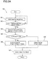
- Figure 3A illustrates a flow diagram 100 of scanning check point duration time for each check point CP ij which is formed by a sensor 5.
- Figure 3B illustrates a plurality of check points CP ij corresponding to a plurality of sensors 5 arranged on the landing plate 2 at the exit of the escalator 3 as described above with reference to FIG. 2 .
- each checkpoint CP ij is arranged on a coordinate grid 6 on the sensor system 1 disposed at the exit of landing plate 2, where the width direction corresponds to X-axis and the length direction corresponds to Y-axis, and each checkpoint CP ij can be identified by an ordered pair of numbers (i, j) in the X-Y coordinate.
- the ordered pair (x, y) can be indicated as CP xy , where x denotes X-coordinate and y denotes Y-coordinate on the coordinate grid 6.
- the origin CP 00 is located at the intersection of the line on the X-axis and the line on the Y-axis.
- CP ij denotes an arbitrary checkpoint on the sensor system 1.
- each checkpoint CP ij is scanned for a programmable amount of time, for example, 100 milliseconds for scanning a passenger lingered on the landing plate 2, i.e. a passenger stayed longer than is necessary on the landing plate 2 after getting off the escalator 3.
- the scanning is carried out for a predetermined interval (100 milliseconds) (step 102)
- the input state for all checkpoints, CP 00 to CP XY is determined (step 103).
- step 107 When the check point status of each of all sensors 5 is derived (step 107), then the check point status is stored in a memory (not shown) and this process continues to monitor a duration time of each checkpoints CP ij for 100 milliseconds intervals in this embodiment. The duration time on each checkpoint, DTcpij derived from this algorithm is then transferred to the next algorithm as shown in FIG. 4 .
- Figure 4 illustrates a flow diagram 200 of determining a status of each check point CP ij .
- duration time of each check point DTcpij is compared with three types of threshold times, X linger , X laid , and X malfunction , for determining checkpoint status of each check point, CP ij _status.
- X linger refers to a duration time considered as a time derived from escalator speed when a passenger starts to linger around the exit of an escalator, for example, duration time of 1 second.
- X laid refers to a duration time considered as a time that any object is placed on any checkpoint CP ij , or a passenger possibly gets stuck on any checkpoint CP ij , for example, duration time of 10 seconds.
- X malfunction denotes a duration time considered as a time where any checkpoint CP ij has been consecutively detected for a predetermined time period and unavailable as a checkpoint, for example, duration time of 1 day.
- the duration time of each check point DTcpij derived from the algorithm 100 is compared with a first threshold time X linger . If the duration time DTcpij is less than X linger , then the status of the checkpoint, CP ij _status, is determined to be in a normal condition, CP_NORMAL (step 204). In other words, there is no passenger lingered on the checkpoint or no object placed on the checkpoint CP ij . If the duration time DTcpij exceeds the first threshold time X linger , then the duration time DTcpij is compared with a second threshold time, X laid (step 202).
- the checkpoint status CP ij _status is determined to be in a lingering condition, CP_LINGERING (step 205). It follows that there is a passenger lingered or stayed longer than the first threshold time (e.g. for more than 1 second) on the checkpoint CP ij after getting off the escalator 3. If the duration time DTcpij exceeds the second threshold time X laid , then the duration time DTcpij is compared with a third threshold time, X malfunction (step 203).
- the status of the checkpoint CP ij _status is determined to be in a laid condition, CP_LAID (step 206). Namely, there is an object placed on the checkpoint CP ij or a passenger getting stuck on the checkpoint CP ij for more than a predetermined time period (e.g. 10 seconds). If the duration time DTcpij exceeds the third threshold time X malfunction , the checkpoint status CP ij _status is determined to be in a malfunctioned condition, CP_MALFUNCTIONED (step 207).
- check point status of each checkpoint, CP ij _status derived from this algorithm 200 is stored in a memory (step 208) and this process returns to step 201 to continue this process.
- the check point status of each sensor 5 is then transferred to the next algorithm as shown in FIG. 5A .
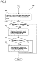
- FIG. 5A and Figure 6 illustrate a series of flow diagrams 300 of the detection algorithm of occupied width of passengers lingered on the landing plate according to the present invention.
- operation starts from checking the check point status of each row "i" of the checkpoints CP ij arranged on the coordinate grid 6 on the sensor system 1 as shown in Figures 3B and 5B .
- the check point status of each row "i" is derived from the status of each checkpoint, CP ij _status, which is obtained from the algorithm 200 shown in FIG. 4 .
- the row “i" is defined by a row 7 of checkpoints, CP i0 , Cp i1 , ..., CP iY , arranged along the moving direction, i.e. arranged along the entire length (Y-axis) of the sensor system 1.
- the row “1" is the 1st row of checkpoints, CP 10 , CP 11 , CP 12 , ..., CP 1Y .
- the control unit immediately generates an alert message to a building owner or a building administrative company to urge checking the escalator 3 and also warns passengers on the escalator 3 that there is an object detected at the exit ahead.
- alert message may be transmitted to a building owner or a building administrative company via any means including, but not limited to, internet, fixed lines, etc.
- the alert message to passengers may be any audible message using speakers or any other audible devices, any visual message using displays, indicator lamps or any other visual devices, or a combination of both.
- the control unit At step 307, if the malfunctioned checkpoint count per row exceeds a predetermined count, the control unit generates a report to a building owner or a building administrative company to replace whole sensor system 1.
- step 309 in FIG. 6 which derives the percentage of rows (% CP ocpd ) occupied by passengers lingered on the landing plate 2 at the exit of the escalator 3 with respect to the total number of rows "X".
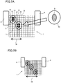
- the percentage of rows occupied by passengers lingered on the landing plate 2 may include extended "ON" area which will be better understood with reference to Figure 7A .
- the extended "ON" area 10 is added to extend the area 9 where the checkpoints detect a passenger lingered on the landing plate 2. Assuming that there is a passenger lingered on the landing plate 2 at the exit of the escalator 3.
- the sensor system 1 will detect eight checkpoints 11 in a lingering condition as shown in FIG. 7A , each of four checkpoints corresponds to one of his footprints.
- the four rows 12, 13, 14, 15 corresponding to the eight checkpoints 11 in a lingering condition are counted as occupied rows.
- three to five additional rows corresponding to the extended "ON" area 10 are counted as occupied rows in addition to the rows corresponding to the area 9 where the input status is CP_LINGERING, CP_LAID, or CP_MALFUNCTIONED.
- the rows “i” and “k” include at least one CP_LINGERING, CP_LAID, or CP_MALFUNCTIONED checkpoint, then the additional rows “i-5", “i-4", “i-3", “i-2”, “i-1” and “i+1", “i+2", “i+3", “i+4", "i+5" are added to the row "i" as occupied rows.
- the additional rows “k-5”, “k-4”, “k-3”, “k-2”, “k-1” and “k+1”, “k+2", “k+3”, “k+4", “k+5" are added to the row "k” as occupied rows.
- more than five additional rows corresponding to the extended "ON" area may be counted as occupied rows in addition to the rows which include at least one checkpoint in a CP_LINGERING, CP_LAID, or CP_MALFUNCTIONED condition.
- the number of the additional rows corresponding to the width of the extended "ON" area may be selected depending on the use situation of the sensor system 1, such as the entire width of the escalator 3, the spacing between each sensor 5, etc.
- the percentage of occupied rows (% CP ocpd ), including both rows having at least one checkpoint in a CP_LINGERING, CP_LAID, or CP_MALFUNCTIONED condition and rows corresponding to the extended "ON" area, with respect to the total number of rows is determined.
- the percentage of occupied rows corresponds to the occupied width of one or more passengers/objects as shown by arrow 19 in FIGS. 7A-7D .
- the control unit compares the percentage of occupied rows (% CP ocpd ) with a first threshold rate, X slowdown [%] (step 310).
- X slowdown denotes a predetermined value in percentage which triggers the escalator 3 to slow down. In one embodiment, X slowdown is set to fifty percent (50%). If the percentage of occupied rows (% CP ocpd ), i.e. the occupied width 19 of passengers lingered at the exit of the escalator 3 exceeds X slowdown as shown in FIG. 7B , then the control unit transmits a signal to slow down the escalator 3 based on the % CP ocpd value and indicate passengers the deceleration of the escalator 3 audibly and/or visually (step 311), followed by proceeding to step 312.
- multi-level speed control of the escalator 3 may be provided based on the comparison of the percentage of occupied rows (% CP ocpd ) with a plurality of X slowdown values.
- a plurality of X slowdown values may be preset as appropriate according to the service conditions of the escalator 3. If the percentage of occupied rows (% CP ocpd ) is less than X slowdown , the control unit determines that the escalator 3 is in a normal condition and returns to step 301 ( FIG. 5A ) to repeat process.
- the percentage of occupied rows is further compared with a second threshold rate, X stop [%] (step 312).
- X stop is a predetermined value in percentage which triggers the escalator 3 to stop.
- X slowdown is set to ninety percent (90%). However, it should be understood that X slowdown value may be determined as appropriate according to the service conditions of the escalator 3.
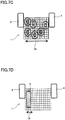
- % CP ocpd the percentage of occupied rows (% CP ocpd ), i.e. the occupied width 19 of passengers lingered at the exit of the escalator 3 exceeds X stop as shown in FIG.
- control unit 7C immediately transmits a signal to stop the escalator 3 and indicate passengers the emergency stop audibly and/or visually, as well as generating a report to a building owner or a building administrative company (step 313).
- the algorithm 300 returns to step 301 ( FIG. 5A ) to repeat process.
- control unit determines that the escalator 3 is in a lingering condition (where X slowdown [%] ⁇ % CP ocpd [%] ⁇ X stop [%]) and returns to step 301 ( FIG. 5A ) to repeat process.
- the present invention by employing a plurality of sensor switches arranged in a grid pattern in the width direction and the length direction over a landing area of a landing plate at the exit of an escalator as a sensor system, it is possible to detect abnormal conditions, including crowding with passengers getting off the escalator at the exit, presence of an object at the exit, and malfunction of the system, with the use of a simple and inexpensive structure compared to a conventional abnormal condition detection system for an escalator including optical sensors and the like.
- the sensor system of the present invention since the sensor system of the present invention has a structure that allows for an easy installation on the landing plate of a conventional escalator system, it can be easily retrofitted to existing escalator system.
- the sensor system of the present invention is configured to detect only the residence time of a person on a landing plate in response to a ON state signal of sensors rather than detecting the number of people staying in the vicinity of the exit or moving direction of the people, and configured to control operation of the escalator based on the residence time of a person on the landing plate and the occupied width of the person with respect to the width of the escalator. Therefore, by applying the sensor system with simple control algorithm in accordance with the present invention, more simple and more accurate control can be achieved as compared with conventional escalator control systems.
Landscapes
- Engineering & Computer Science (AREA)
- Human Computer Interaction (AREA)
- Manufacturing & Machinery (AREA)
- Physics & Mathematics (AREA)
- General Physics & Mathematics (AREA)
- Automation & Control Theory (AREA)
- Escalators And Moving Walkways (AREA)
Abstract
Description
- The present invention relates to a sensor system that is arranged on a landing plate of an escalator. In particular, the present invention relates to a sensor system for controlling escalator in order to avoid the risks of injuries that occur on escalators during congested periods and a method of controlling the same.
- In recent years, the number of accidents that occur on escalators such as falling like dominos has been increasing, especially on escalators installed in train stations and venues where various programs are being featured, including concerts, exhibitions and sports events. Such accidents are primarily caused by crowds formed in the vicinity of the exit of an escalator, as they get stuck with nowhere to go, causing passengers getting off the escalator to push back to the escalator. Therefore, there is an increasing need for providing an escalator system to prevent such accidents and minimize the potential risks for injuries during congestion on an escalator.
- For example,
JP-A-2004-244183 - Accordingly, it would be desirable to provide a simple sensor system that has fewer parts, is easy to install, and that can also be retrofitted to existing escalators.
- It would also be desirable to provide a method of controlling an escalator using such sensor system that only requires a simple controlling method.
- According to one aspect of the present invention, a sensor system for controlling operation of an escalator arranged on a landing plate at the exit of the escalator is disclosed. The sensor system includes a plurality of sensors arranged over a landing area of the landing plate. Each sensor is disposed at predetermined intervals with respect to the width direction along the width between two balustrades and the length direction along the moving direction of the escalator. Each sensor is configured to detect a predetermined pressure so as to obtain a transition of ON/OFF states in response to a load presence. The sensor system further includes a control unit for scanning ON state signals of all sensors within a predetermined time period continuously. The control unit is configured to detect a presence of a passenger lingered on the sensor system in response to a duration time of ON state signal of each sensor, and configured to decelerate or stop the escalator in response to a rate of occupied width of passengers lingered on the sensor system with respect to the entire width of the sensor system. The occupied width can be obtained based on the width of the area of the sensors detected the presence of passengers lingered on the sensor system.
- In some embodiments, in addition to the features above, or as an alternative, each sensor may be disposed at equally spaced intervals between 1 and 30 centimeters.
- In some embodiments, in addition to the features above, or as an alternative, each sensor may be configured to detect a pressure between 100 to 200 g/cm2 so as to obtain a transition of ON/OFF states.
- In some embodiments, in addition to the features above, or as an alternative, the sensor system may be arranged in a range of at least one meter along the length direction from a comb plate.
- In some embodiments, in addition to the features above, or as an alternative, the control unit may be configured to scan ON state signals of all sensors at intervals between 100 and 200 milliseconds.
- In some embodiments, in addition to the features above, or as an alternative, the control unit may be configured to detect a presence of a passenger lingered on the sensor system if the duration time of the ON state signal of a sensor exceeds a first threshold time.
- In some embodiments, in addition to the features above, or as an alternative, the control unit may be configured to decelerate the escalator if the rate of occupied width of passengers lingered on the sensor system exceeds a first threshold rate.
- In some embodiments, in addition to the features above, or as an alternative, the control unit may be configured to stop the escalator if the rate of occupied width of passengers lingered on the sensor system exceeds a second threshold rate greater than the first threshold rate.
- In some embodiments, in addition to the features above, or as an alternative, the occupied width of passengers may include a width of the area where the sensors detect a passenger lingered on the sensor system and a width of an additional area to extend the width of the area where sensors detect a passenger lingered on the sensor system so as to simulate human body width.
- In some embodiments, in addition to the features above, or as an alternative, the control unit may be further configured to detect a presence of an object placed on the sensor system if the duration time of the ON state signal of a sensor exceeds a second threshold time longer than the first threshold time.
- In some embodiments, in addition to the features above, or as an alternative, the control unit may be further configured to detect a malfunction of the sensor if the duration time of the ON state signal of the sensor exceeds a third threshold time.
- In some embodiments, in addition to the features above, or as an alternative, the sensor may be selected from a group including a mechanical micro switch, a pressure sensor, an electrically conductive rubber for detecting resistance based on load pressure, and a metal-wire sensor formed by a plurality of wires arranged over the landing area of the landing plate.
- In some embodiments, in addition to the features above, or as an alternative, the sensor may comprise a metal-wire sensor formed by a plurality of wires arranged in a grid layout and configured to obtain ON state signal by contacting two lines intersecting with each other in response to a load presence.
- According to another aspect of the present invention, a method of controlling operation of escalator using a sensor system arranged on a landing plate at the exit of the escalator is disclosed. The sensor system includes a plurality of sensors arranged over a landing area of the landing plate. Each sensor is disposed at predetermined grid intervals with respect to the width direction along the width between two balustrades and the length direction along the moving direction of the escalator. Each sensor is configured to detect a predetermined pressure so as to obtain a transition of ON/OFF states in response to a load presence. The method includes: scanning ON state signals of all sensors within a predetermined time period continuously to monitor a duration time of each ON state signal; comparing the duration time of each ON state signal with a threshold time to detect a presence of a passenger lingered on the sensor system; determining if each row of sensors arranged along the length direction of the sensor system at the predetermined grid intervals includes any sensor having duration time exceeding the threshold time; determining a rate of occupied width of passengers lingered on the sensor system with respect to the entire width of the sensor system based on the number of rows which include any sensor having duration time exceeding the threshold time; decelerating the escalator if the rate of occupied width of passengers lingered on the sensor system exceeds a first threshold rate; and stopping the operation of the escalator if the rate of occupied with of passengers lingered on the sensor system exceeds a second threshold rate.
- In some embodiments, in addition to the features above, or as an alternative, the method of controlling operation of escalator using a sensor system further may include: comparing the duration time of each ON state signal exceeding the threshold time with a second threshold time; and generating an alert to passengers on the escalator about the presence of an object on the sensor system if the duration time exceeds the second threshold time.
- In some embodiments, in addition to the features above, or as an alternative, the method of controlling operation of escalator using a sensor system further may include: comparing the duration time of each ON state signal exceeding the second threshold time with a third threshold time; determining if each row of sensors arranged along the length direction of the sensor system at the predetermined grid intervals includes any sensor having duration time exceeding the third threshold time; counting the number of sensors in each row exceeding the third threshold time; and generating a report to urge replacing whole sensor system if the number of sensors in each row exceeding the third threshold time exceeds a predetermined number.
- In some embodiments, in addition to the features above, or as an alternative, each sensor may be disposed at grid intervals between 1 and 30 centimeters.
- In some embodiments, in addition to the features above, or as an alternative, each sensor may be configured to detect a pressure between 100 to 200 g/cm2 so as to obtain a transition of ON/OFF states.
- In some embodiments, in addition to the features above, or as an alternative, the sensor system may be arranged in a range of at least one meter along the length direction from a comb plate.
- In some embodiments, in addition to the features above, or as an alternative, the control unit may be configured to scan ON state signals of all sensors at intervals between 100 and 200 milliseconds.
- In some embodiments, in addition to the features above, or as an alternative, the threshold time may be set in a range between one and two seconds.
- In some embodiments, in addition to the features above, or as an alternative, the first threshold rate may be set to fifty percent of the entire width of the sensor system.
- In some embodiments, in addition to the features above, or as an alternative, the second threshold rate may be set to ninety percent of the entire width of the sensor system.
- In some embodiments, in addition to the features above, or as an alternative, determining a rate of occupied width of passengers lingered on the sensor system is carried out based on the number of rows including rows corresponding to the area where the sensors detect a passenger lingered on the sensor system and additional rows corresponding to an additional area to extend the area where sensors detect a passenger lingered on the sensor system so as to simulate human body width.
- In some embodiments, in addition to the features above, or as an alternative, the second threshold time may be set to ten seconds or more.
- In some embodiments, in addition to the features above, or as an alternative, the third threshold time is set to one day or more.
- These and other aspects of this disclosure will become more readily apparent from the following description and the accompanying drawings, which can be briefly described as follows.
-
Figure 1 is a schematic view showing one possible arrangement of a sensor system according to the present invention installed in a landing plate at the exit of an escalator. -
Figure 2 is a top view of the sensor system according to the present invention installed in the landing plate at the exit of an escalator. -
Figure 3A is a flow diagram showing a method of scanning check point duration time in accordance with the present invention. -
Figure 3B illustrates a plurality of checkpoints formed by a plurality of sensors arranged on the sensor system according to the present invention. -
Figure 4 is a flow diagram of determining a status of each check point in accordance with the present invention. -
Figure 5A is a flow diagram of determining if each row of the checkpoints arranged along the length direction of the sensor system in accordance with the present invention includes any checkpoint in an abnormal condition. -
Figure 5B illustrates a series of rows of the checkpoints arranged in a coordinate grid on the sensor system in accordance with the present invention. -
Figure 6 is a flow diagram of determining occupied width of passengers lingered on the landing plate at the exit of an escalator according to the present invention. -
Figure 7A illustrates occupied width of a passenger which includes rows each having at least one checkpoint in a lingering condition and additional rows corresponding to an extended "ON" area which simulate human body width. -
Figure 7B illustrates occupied width of passengers lingered on the landing plate of an escalator exceeding fifty percent of the entire width of the escalator. -
Figure 7C illustrates occupied width of passengers lingered on the landing plate of an escalator exceeding ninety percent of the entire width of the escalator. -
Figure 7D illustrates that there is an object detected on the landing plate of an escalator. -
Figure 1 shows asensor system 1 in accordance with the present invention installed in alanding plate 2 at the exit of anescalator 3. As shown inFIG. 1 , thesensor system 1 is arranged over a landing area of thelanding plate 2 of theescalator 3, i.e. the area which passengers most likely step on when exiting theescalator 3. Generally, thesensor system 1 is arranged along the entire width between twobalustrades 4 of theescalator 3 and arranged in a range of at least one meter (or at least more than the average length of stride) along the moving direction of theescalator 3 from an escalator comb plate (not shown). It should be understood that thesensor system 1 disposed on thelanding plate 2 may be arranged over a width larger than the entire width between twobalustrades 4. However, the entire length less than one meter along the moving direction of theescalator 3 is not preferable since it may not be able to correctly detect passengers' movement. -
Figure 2 illustrates a top view of thesensor system 1 of the present invention installed in thelanding plate 2 at the exit of theescalator 3. As shownFIG. 2 , a plurality of sensors 5 (or checkpoints, CPij) is placed on thelanding plate 2. Thesensors 5 are arranged over the entire width between two balustrades 4 (hereinafter referred to as "the width" or "X-direction"), and arranged in a predetermined range, for example, at least one meter along the moving direction of theescalator 3 measured from the escalator comb plate (hereinafter referred to as "the length" or "Y-direction"). Furthermore, thesensors 5 are disposed in both X-direction and Y-direction at predetermined intervals, for example, 1 to 2 cm intervals. It should be understood that the spacing between eachsensor 5 may be less than 1 cm intervals. However, the interval of more than 30 cm may not be preferable since it may not be able to correctly detect passengers' movement. - The
sensor 5 constituting each check point may be any type of sensor switch including, but not limited to, any devices that can detect inputs based on load pressures consecutively such as a mechanical micro switch and a pressure sensor, an electrically conductive rubber which detects resistance based on load pressure, or a metal-wire sensor formed by a plurality of metal wires arranged in any shapes across the width direction (X-direction) and the length direction (Y-direction) of a landing plate of an escalator. Specifically, a metal-wire sensor configured to be arranged in a grid layout and configured to sense ON input by contacting two lines, one from lines in the X-direction and the other from lines in the Y-direction, in response to a passenger stepping on the lines is advantageous in that it is relatively non-breakable and inexpensive. - Each of the
successive sensors 5 is configured to detect a predetermined pressure, for example, a pressure of 100 to 200 g/cm2 so as to obtain a transition of ON/OFF states in response to a load presence. In other words, eachsensor 5 is triggered as ON when the load exceeds 100 to 200 g/cm2 in response to a passenger stepping on thesensor 5, and returns to OFF when the load gets lighter than the same predetermined value. Moreover, as described later with reference toFIG. 3A , all checkpoints CPij where thesensors 5 are arranged are configured to be scanned in a predetermined cycle, for example, at 100 milliseconds (ms) intervals, so as to constantly update the change in the input state (ON states) for tracking the movement of passengers getting off the escalator at the exit. It should be understood that the detecting pressure of the ON/OFF states may be less than 100 g/cm2. However, the detecting pressure greater than 200 g/cm2 is not preferable since it may not be able to correctly detect passengers' movement. - The method of detecting a passenger lingered around the exit of an
escalator 3 and controlling the escalator operation in accordance with the present invention is described with reference toFIG. 3A to FIG. 6 . -
Figure 3A illustrates a flow diagram 100 of scanning check point duration time for each check point CPij which is formed by asensor 5.Figure 3B illustrates a plurality of check points CPij corresponding to a plurality ofsensors 5 arranged on thelanding plate 2 at the exit of theescalator 3 as described above with reference toFIG. 2 . - As shown in
FIG. 3B , each checkpoint CPij is arranged on a coordinategrid 6 on thesensor system 1 disposed at the exit oflanding plate 2, where the width direction corresponds to X-axis and the length direction corresponds to Y-axis, and each checkpoint CPij can be identified by an ordered pair of numbers (i, j) in the X-Y coordinate. For example, the ordered pair (x, y) can be indicated as CPxy, where x denotes X-coordinate and y denotes Y-coordinate on the coordinategrid 6. As shown inFIG. 3B , the origin CP00 is located at the intersection of the line on the X-axis and the line on the Y-axis. Note that CPij denotes an arbitrary checkpoint on thesensor system 1. - Again referring to
FIG. 3A , operation starts from checking scanning interval time of all sensors 5 (step 101). In this embodiment, each checkpoint CPij is scanned for a programmable amount of time, for example, 100 milliseconds for scanning a passenger lingered on thelanding plate 2, i.e. a passenger stayed longer than is necessary on thelanding plate 2 after getting off theescalator 3. When the scanning is carried out for a predetermined interval (100 milliseconds) (step 102), the input state for all checkpoints, CP00 to CPXY, is determined (step 103). If thesensor system 1 detects that a passenger is stepped on asensor 5 on a checkpoint CPij when getting off an escalator, i.e. if CPij input is ON (step 104), then a control unit (not shown) for operating check point durationtime monitoring algorithm 100 as shown inFIG. 3A increments a counter DTcpij by 0.1 seconds (step 105). If asensor 5 on a checkpoint CPij does not detect a passenger exiting the escalator, the control unit for operating this algorithm resets the duration time on a checkpoint CPij as DTcpij = 0sec (step 106). When the check point status of each of allsensors 5 is derived (step 107), then the check point status is stored in a memory (not shown) and this process continues to monitor a duration time of each checkpoints CPij for 100 milliseconds intervals in this embodiment. The duration time on each checkpoint, DTcpij derived from this algorithm is then transferred to the next algorithm as shown inFIG. 4 . -
Figure 4 illustrates a flow diagram 200 of determining a status of each check point CPij. In this algorithm, duration time of each check point DTcpij is compared with three types of threshold times, Xlinger, Xlaid, and Xmalfunction, for determining checkpoint status of each check point, CPij_status. In this specification, Xlinger refers to a duration time considered as a time derived from escalator speed when a passenger starts to linger around the exit of an escalator, for example, duration time of 1 second. Xlaid refers to a duration time considered as a time that any object is placed on any checkpoint CPij, or a passenger possibly gets stuck on any checkpoint CPij, for example, duration time of 10 seconds. Xmalfunction denotes a duration time considered as a time where any checkpoint CPij has been consecutively detected for a predetermined time period and unavailable as a checkpoint, for example, duration time of 1 day. - At
step 201, the duration time of each check point DTcpij derived from thealgorithm 100 is compared with a first threshold time Xlinger. If the duration time DTcpij is less than Xlinger, then the status of the checkpoint, CPij_status, is determined to be in a normal condition, CP_NORMAL (step 204). In other words, there is no passenger lingered on the checkpoint or no object placed on the checkpoint CPij. If the duration time DTcpij exceeds the first threshold time Xlinger, then the duration time DTcpij is compared with a second threshold time, Xlaid (step 202). If the duration time DTcpij is less than Xlaid, the checkpoint status CPij_status is determined to be in a lingering condition, CP_LINGERING (step 205). It follows that there is a passenger lingered or stayed longer than the first threshold time (e.g. for more than 1 second) on the checkpoint CPij after getting off theescalator 3. If the duration time DTcpij exceeds the second threshold time Xlaid, then the duration time DTcpij is compared with a third threshold time, Xmalfunction (step 203). If the duration time DTcpij is less than the third threshold time Xmalfunction, the status of the checkpoint CPij_status is determined to be in a laid condition, CP_LAID (step 206). Namely, there is an object placed on the checkpoint CPij or a passenger getting stuck on the checkpoint CPij for more than a predetermined time period (e.g. 10 seconds). If the duration time DTcpij exceeds the third threshold time Xmalfunction, the checkpoint status CPij_status is determined to be in a malfunctioned condition, CP_MALFUNCTIONED (step 207). The check point status of each checkpoint, CPij_status derived from thisalgorithm 200 is stored in a memory (step 208) and this process returns to step 201 to continue this process. The check point status of eachsensor 5 is then transferred to the next algorithm as shown inFIG. 5A . -
Figure 5A andFigure 6 illustrate a series of flow diagrams 300 of the detection algorithm of occupied width of passengers lingered on the landing plate according to the present invention. Atstep 301, operation starts from checking the check point status of each row "i" of the checkpoints CPij arranged on the coordinategrid 6 on thesensor system 1 as shown inFigures 3B and5B . The check point status of each row "i" is derived from the status of each checkpoint, CPij_status, which is obtained from thealgorithm 200 shown inFIG. 4 . With reference toFigure 5B , it can be seen that the row "i" is defined by arow 7 of checkpoints, CPi0, Cpi1, ..., CPiY, arranged along the moving direction, i.e. arranged along the entire length (Y-axis) of thesensor system 1. For example, the row "1" is the 1st row of checkpoints, CP10, CP11, CP12, ..., CP1Y. - At
step 302, the algorithm shown inFIG. 5A checks to see whether each row "i" of the checkpoints CPij arranged on the coordinategrid 6 on thesensor system 1 includes any checkpoint in a lingering status CP_LINGERING or in a laid status CP_LAID. If the row "i" includes any checkpoint in a CP_LINGERING or CP_LAID status, the row is determined to be in a occupied condition and the control unit for carrying out thisalgorithm 300 sets CProw_i_status=OCCUPIED (step 303), followed by the incrementing of the count "i" by one to check next row "i+1" (step 304). Atstep 303, if the row "i" includes any checkpoint in a CP_LAID status, it follows that there is anobject 8 placed on thelanding plate 2 as shown inFIG. 7D or a passenger getting stuck on thelanding plate 2. The control unit immediately generates an alert message to a building owner or a building administrative company to urge checking theescalator 3 and also warns passengers on theescalator 3 that there is an object detected at the exit ahead. Alternatively, the control unit may further transmit a signal to theescalator 3 to slow down theescalator 3 in addition to generating an alert to a building owner/building administrative company and passengers until the checkpoint status CPij_status=CP_LAID disappears. It should be understood that the alert message may be transmitted to a building owner or a building administrative company via any means including, but not limited to, internet, fixed lines, etc. The alert message to passengers may be any audible message using speakers or any other audible devices, any visual message using displays, indicator lamps or any other visual devices, or a combination of both. - If there is no checkpoint in a lingering status CP_LINGERING or in a laid status CP_LAID included in the row "i" at
step 302, the control unit sets CProw_i_status=NOT_OCCUPIED for the corresponding row "i" (step 305) and proceeds to step 306 which checks whether the row "i" includes any checkpoint in a malfunctioned condition, CP_MALFUNCTIONED. If there is no checkpoint in a malfunctioned condition in the row "i", the algorithm proceeds to step 304 which directs the incrementing of the count value i by one and proceeds to step 308. If the row "i" includes any checkpoint in a malfunctioned condition, i.e. if there is any checkpoint where CPij_status=CP_MALFUNCTIONED, then the malfunctioned checkpoint CPij is stored in a memory and the number of the malfunctioned checkpoints per row is counted (step 307), followed by the incrementing of the count "i" by one (step 304) and then proceeds to step 308. Atstep 307, if the malfunctioned checkpoint count per row exceeds a predetermined count, the control unit generates a report to a building owner or a building administrative company to replacewhole sensor system 1. - Subsequently, the control unit checks to see if the count value "i" reaches to the end of row "X" in the coordinate grid 6 (I = = X) (step 308). If the count value does not reach to the end of row "X", then the algorithm returns to step 301 to repeat process. This loop continues until all rows are checked to see whether there is any checkpoint in a lingering status, in a laid status or in a malfunctioned status, with respect to each row "i". When the count value "i" reaches to the end of row "X", the control unit then proceeds to the algorithm in
FIG. 6 which determines the occupied width of passengers lingered on thelanding plate 2 at the exit of theescalator 3 and controls the operation of the escalator based on the occupied width of passengers. - Following the execution of
step 308 inFIG. 5A , the control unit proceeds to step 309 inFIG. 6 which derives the percentage of rows (% CPocpd) occupied by passengers lingered on thelanding plate 2 at the exit of theescalator 3 with respect to the total number of rows "X". Note that the percentage of rows occupied by passengers lingered on the landing plate 2 (hereinafter referred to as "percentage of occupied rows") may include extended "ON" area which will be better understood with reference toFigure 7A . - As shown in
FIG. 7A , the extended "ON"area 10 is added to extend thearea 9 where the checkpoints detect a passenger lingered on thelanding plate 2. Assuming that there is a passenger lingered on thelanding plate 2 at the exit of theescalator 3. Thesensor system 1 will detect eightcheckpoints 11 in a lingering condition as shown inFIG. 7A , each of four checkpoints corresponds to one of his footprints. By executing the algorithm shown inFIG. 5A , the fourrows checkpoints 11 in a lingering condition are counted as occupied rows. However, since the human body width is larger than the width between two footprints (in this case, the total width of fouroccupied rows additional rows area 10 are added to the four occupied rows to simulate human occupied width. Accordingly, both therows additional rows area 10 are counted as occupied row. - In one embodiment, three to five additional rows corresponding to the extended "ON"
area 10 are counted as occupied rows in addition to the rows corresponding to thearea 9 where the input status is CP_LINGERING, CP_LAID, or CP_MALFUNCTIONED. For example, if the rows "i" and "k" include at least one CP_LINGERING, CP_LAID, or CP_MALFUNCTIONED checkpoint, then the additional rows "i-5", "i-4", "i-3", "i-2", "i-1" and "i+1", "i+2", "i+3", "i+4", "i+5" are added to the row "i" as occupied rows. Likewise, the additional rows "k-5", "k-4", "k-3", "k-2", "k-1" and "k+1", "k+2", "k+3", "k+4", "k+5" are added to the row "k" as occupied rows. In another embodiment, more than five additional rows corresponding to the extended "ON" area may be counted as occupied rows in addition to the rows which include at least one checkpoint in a CP_LINGERING, CP_LAID, or CP_MALFUNCTIONED condition. The number of the additional rows corresponding to the width of the extended "ON" area may be selected depending on the use situation of thesensor system 1, such as the entire width of theescalator 3, the spacing between eachsensor 5, etc. - Again referring to
FIG. 6 , atstep 309, the percentage of occupied rows (% CPocpd), including both rows having at least one checkpoint in a CP_LINGERING, CP_LAID, or CP_MALFUNCTIONED condition and rows corresponding to the extended "ON" area, with respect to the total number of rows is determined. The percentage of occupied rows (% CPocpd) corresponds to the occupied width of one or more passengers/objects as shown byarrow 19 inFIGS. 7A-7D . The control unit then compares the percentage of occupied rows (% CPocpd) with a first threshold rate, Xslowdown [%] (step 310). Xslowdown denotes a predetermined value in percentage which triggers theescalator 3 to slow down. In one embodiment, Xslowdown is set to fifty percent (50%). If the percentage of occupied rows (% CPocpd), i.e. the occupiedwidth 19 of passengers lingered at the exit of theescalator 3 exceeds Xslowdown as shown inFIG. 7B , then the control unit transmits a signal to slow down theescalator 3 based on the % CPocpd value and indicate passengers the deceleration of theescalator 3 audibly and/or visually (step 311), followed by proceeding to step 312. It should be understood that multi-level speed control of theescalator 3 may be provided based on the comparison of the percentage of occupied rows (% CPocpd) with a plurality of Xslowdown values. A plurality of Xslowdown values may be preset as appropriate according to the service conditions of theescalator 3. If the percentage of occupied rows (% CPocpd) is less than Xslowdown, the control unit determines that theescalator 3 is in a normal condition and returns to step 301 (FIG. 5A ) to repeat process. - Following the
step 311, the percentage of occupied rows (% CPocpd) is further compared with a second threshold rate, Xstop [%] (step 312). Xstop is a predetermined value in percentage which triggers theescalator 3 to stop. In one embodiment, Xslowdown is set to ninety percent (90%). However, it should be understood that Xslowdown value may be determined as appropriate according to the service conditions of theescalator 3. Atstep 312, if the percentage of occupied rows (% CPocpd), i.e. the occupiedwidth 19 of passengers lingered at the exit of theescalator 3 exceeds Xstop as shown inFIG. 7C , the control unit immediately transmits a signal to stop theescalator 3 and indicate passengers the emergency stop audibly and/or visually, as well as generating a report to a building owner or a building administrative company (step 313). Following the execution ofstep 313, thealgorithm 300 returns to step 301 (FIG. 5A ) to repeat process. - If the percentage of occupied rows (% CPocpd) is less than Xstop, the control unit determines that the
escalator 3 is in a lingering condition (where Xslowdown [%] < % CPocpd [%] < Xstop [%]) and returns to step 301 (FIG. 5A ) to repeat process. - According to the present invention, by employing a plurality of sensor switches arranged in a grid pattern in the width direction and the length direction over a landing area of a landing plate at the exit of an escalator as a sensor system, it is possible to detect abnormal conditions, including crowding with passengers getting off the escalator at the exit, presence of an object at the exit, and malfunction of the system, with the use of a simple and inexpensive structure compared to a conventional abnormal condition detection system for an escalator including optical sensors and the like. In particular, since the sensor system of the present invention has a structure that allows for an easy installation on the landing plate of a conventional escalator system, it can be easily retrofitted to existing escalator system.
- The sensor system of the present invention is configured to detect only the residence time of a person on a landing plate in response to a ON state signal of sensors rather than detecting the number of people staying in the vicinity of the exit or moving direction of the people, and configured to control operation of the escalator based on the residence time of a person on the landing plate and the occupied width of the person with respect to the width of the escalator. Therefore, by applying the sensor system with simple control algorithm in accordance with the present invention, more simple and more accurate control can be achieved as compared with conventional escalator control systems.
- Although a particular embodiment has been described with respect to installation into an escalator, it should be understood that it can also be utilized for a moving sidewalk.
- While the present invention has been particularly shown and described with reference to the exemplary embodiments as illustrated in the drawings, it will be recognized by those skilled in the art that various modifications may be made without departing from the spirit and scope of the invention as disclosed in the accompanying claims.
Claims (15)
- A sensor system for controlling operation of an escalator arranged on a landing plate at the exit of the escalator, the sensor system comprising:a plurality of sensors arranged over a landing area of the landing plate, each sensor disposed at predetermined intervals with respect to the width direction along the width between two balustrades and the length direction along the moving direction of the escalator, each sensor configured to detect a predetermined pressure so as to obtain a transition of ON/OFF states in response to a load presence; anda control unit for scanning ON state signals of all sensors within a predetermined time period continuously, the control unit configured to detect a presence of a passenger lingered on the sensor system in response to a duration time of ON state signal of each sensor, and configured to decelerate or stop the escalator in response to a rate of occupied width of passengers lingered on the sensor system with respect to the entire width of the sensor system.
- The sensor system of claim 1, wherein each sensor is disposed at equally spaced intervals between 1 and 30 centimeters.
- The sensor system of claim 1 or 2, wherein each sensor is configured to detect a pressure between 100 to 200 g/cm2 so as to obtain a transition of ON/OFF states.
- The sensor system of any of claims 1 to 3, wherein the sensor system is arranged in a range of at least one meter along the length direction from a comb plate.
- The sensor system of any of claims 1 to 4, wherein the control unit is configured to scan ON state signals of all sensors at intervals between 100 and 200 milliseconds.
- The sensor system of any of claims 1 to 5, wherein the control unit is configured to detect a presence of a passenger lingered on the sensor system if the duration time of the ON state signal of a sensor exceeds a first threshold time.
- The sensor system of any of claims 1 to 6, wherein the control unit is configured to decelerate the escalator if the rate of occupied width of passengers lingered on the sensor system exceeds a first threshold rate; wherein particularly the control unit is configured to stop the escalator if the rate of occupied width of passengers lingered on the sensor system exceeds a second threshold rate greater than the first threshold rate.
- The sensor system of any of claims 1 to 7, wherein the occupied width of passengers includes a width of the area where the sensors detect a passenger lingered on the sensor system and a width of an additional area to extend the width of the area where sensors detect a passenger lingered on the sensor system so as to simulate human body width.
- The sensor system of any of claims 6 to 8, wherein the control unit is further configured to detect a presence of an object placed on the sensor system if the duration time of the ON state signal of a sensor exceeds a second threshold time longer than the first threshold time; and/or wherein the control unit is further configured to detect a malfunction of the sensor if the duration time of the ON state signal of the sensor exceeds a third threshold time.
- The sensor system of any of claims 1 to 9, wherein the sensor is selected from a group including a mechanical micro switch, a pressure sensor, an electrically conductive rubber for detecting resistance based on load pressure, and a metal-wire sensor formed by a plurality of wires arranged over the landing area of the landing plate; wherein particularly the sensor comprises a metal-wire sensor formed by a plurality of wires arranged in a grid layout and configured to obtain ON state signal by contacting two lines intersecting with each other in response to a load presence.
- A method of controlling operation of escalator using a sensor system arranged on a landing plate at the exit of the escalator, the sensor system comprising a plurality of sensors arranged over a landing area of the landing plate, each sensor disposed at predetermined grid intervals with respect to the width direction along the width between two balustrades and the length direction along the moving direction of the escalator, each sensor configured to detect a predetermined pressure so as to obtain a transition of ON/OFF states in response to a load presence, the method comprising:scanning ON state signals of all sensors within a predetermined time period continuously to monitor a duration time of each ON state signal;comparing the duration time of each ON state signal with a threshold time to detect a presence of a passenger lingered on the sensor system;determining if each row of sensors arranged along the length direction of the sensor system at the predetermined grid intervals includes any sensor having duration time exceeding the threshold time;determining a rate of occupied width of passengers lingered on the sensor system with respect to the entire width of the sensor system based on the number of rows which include any sensor having duration time exceeding the threshold time; decelerating the escalator if the rate of occupied width of passengers lingered on the sensor system exceeds a first threshold rate; andstopping the operation of the escalator if the rate of occupied with of passengers lingered on the sensor system exceeds a second threshold rate.
- The method of claim 11, wherein the sensor system used in the method is configured as claimed in any of claims 1 to 10.
- The method of claim 11 or 12, further comprising:comparing the duration time of each ON state signal exceeding the threshold time with a second threshold time; andgenerating an alert to passengers on the escalator about the presence of an object on the sensor system if the duration time exceeds the second threshold time; the method particularly further comprising:comparing the duration time of each ON state signal exceeding the second threshold time with a third threshold time;determining if each row of sensors arranged along the length direction of the sensor system at the predetermined grid intervals includes any sensor having duration time exceeding the third threshold time;counting the number of sensors in each row exceeding the third threshold time; andgenerating a report to urge replacing whole sensor system if the number of sensors in each row exceeding the third threshold time exceeds a predetermined number.
- The method of any of claims 11 to 13, wherein the threshold time is set in a range between one and two seconds; and/or wherein the first threshold rate is set to fifty percent of the entire width of the sensor system; and/or wherein the second threshold rate is set to ninety percent of the entire width of the sensor system.
- The method of any of claims 11 to 14, wherein the second threshold time is set to ten seconds or more, and/or wherein the third threshold time is set to one day or more.
Applications Claiming Priority (1)
| Application Number | Priority Date | Filing Date | Title |
|---|---|---|---|
| US15/337,784 US20180118522A1 (en) | 2016-10-28 | 2016-10-28 | Sensor on escalator landing plate |
Publications (2)
| Publication Number | Publication Date |
|---|---|
| EP3315451A1 true EP3315451A1 (en) | 2018-05-02 |
| EP3315451B1 EP3315451B1 (en) | 2025-05-07 |
Family
ID=60190732
Family Applications (1)
| Application Number | Title | Priority Date | Filing Date |
|---|---|---|---|
| EP17198897.5A Active EP3315451B1 (en) | 2016-10-28 | 2017-10-27 | Sensor on escalator landing plate |
Country Status (4)
| Country | Link |
|---|---|
| US (1) | US20180118522A1 (en) |
| EP (1) | EP3315451B1 (en) |
| JP (1) | JP7027120B2 (en) |
| CN (1) | CN108002195B (en) |
Cited By (1)
| Publication number | Priority date | Publication date | Assignee | Title |
|---|---|---|---|---|
| JP2019206898A (en) * | 2018-05-29 | 2019-12-05 | 慈溪市双偉道路設施有限公司Cixi Shuangwei Road Facilities Co.,Ltd. | Road laying assembly component |
Families Citing this family (3)
| Publication number | Priority date | Publication date | Assignee | Title |
|---|---|---|---|---|
| JP6927234B2 (en) | 2016-11-29 | 2021-08-25 | ソニーグループ株式会社 | Information processing equipment, information processing methods and programs |
| JP7136164B2 (en) * | 2020-09-25 | 2022-09-13 | フジテック株式会社 | passenger conveyor |
| US20250042699A1 (en) * | 2023-08-02 | 2025-02-06 | Otis Elevator Company | Escalator entrapment detection system |
Citations (5)
| Publication number | Priority date | Publication date | Assignee | Title |
|---|---|---|---|---|
| JPH07187535A (en) * | 1993-12-28 | 1995-07-25 | Hitachi Building Syst Eng & Service Co Ltd | Traffic flow survey equipment |
| JP2004244183A (en) | 2003-02-14 | 2004-09-02 | Toshiba Elevator Co Ltd | Escalator device |
| JP2007210710A (en) * | 2006-02-07 | 2007-08-23 | Mitsubishi Electric Corp | Passenger conveyor |
| JP2008285263A (en) * | 2007-05-16 | 2008-11-27 | Hitachi Ltd | Passenger conveyor |
| JP2009249064A (en) * | 2008-04-01 | 2009-10-29 | Mitsubishi Electric Building Techno Service Co Ltd | Escalator device |
Family Cites Families (56)
| Publication number | Priority date | Publication date | Assignee | Title |
|---|---|---|---|---|
| US5125481A (en) * | 1990-09-26 | 1992-06-30 | Hideaki Shibata | Diagonal elevation apparatus |
| US5601178A (en) * | 1995-03-16 | 1997-02-11 | Zaharia; Vlad | Detection of escalator safety circuit component operability |
| AUPN605295A0 (en) * | 1995-10-18 | 1995-11-09 | Loderway Pty. Limited | Systems for the conveyance of standing passengers |
| JPH10106384A (en) * | 1996-09-30 | 1998-04-24 | Japan Aviation Electron Ind Ltd | Footprint pattern sensor |
| DE19960491C5 (en) * | 1999-12-15 | 2010-06-10 | Otis Elevator Co., Farmington | Device and method for controlling the drive of a conveyor |
| DE10128840A1 (en) * | 2001-06-15 | 2003-01-09 | Otis Elevator Co | Method and device for controlling the drive of a conveyor |
| US6520310B1 (en) * | 2001-12-27 | 2003-02-18 | Inventio Ag | Combplate load and obstruction sensor apparatus |
| US7382267B2 (en) * | 2005-01-31 | 2008-06-03 | Artis Llc | Systems and methods for area activity monitoring and personnel identification |
| US20070171058A1 (en) * | 2005-08-02 | 2007-07-26 | Latitude Broadband, Inc. | Digital flooring detection system |
| US8267634B2 (en) * | 2005-11-07 | 2012-09-18 | Brooks Automation, Inc. | Reduced capacity carrier, transport, load port, buffer system |
| EP1821088A1 (en) * | 2006-02-16 | 2007-08-22 | IEE International Electronics & Engineering S.A.R.L. | Pressure sensing mat |
| US7407048B2 (en) * | 2006-08-21 | 2008-08-05 | Kone Corporation | Safety switch and method of checked redundancy |
| FI120088B (en) * | 2007-03-01 | 2009-06-30 | Kone Corp | Arrangement and method of monitoring the security circuit |
| US8831972B2 (en) * | 2007-04-03 | 2014-09-09 | International Business Machines Corporation | Generating a customer risk assessment using dynamic customer data |
| US7908237B2 (en) * | 2007-06-29 | 2011-03-15 | International Business Machines Corporation | Method and apparatus for identifying unexpected behavior of a customer in a retail environment using detected location data, temperature, humidity, lighting conditions, music, and odors |
| ITNA20080005A1 (en) * | 2008-01-23 | 2009-07-24 | Luigi Cozzuto | STAIRCASE MOBILE STAIRCASE OF STEPS. |
| DE102008009458A1 (en) * | 2008-02-15 | 2009-08-20 | Kone Corp. | Escalator or moving walkway |
| US7953686B2 (en) * | 2008-03-17 | 2011-05-31 | International Business Machines Corporation | Sensor and actuator based validation of expected cohort behavior |
| US8179219B2 (en) * | 2008-04-04 | 2012-05-15 | Correlated Magnetics Research, Llc | Field emission system and method |
| JP4753320B2 (en) | 2008-09-09 | 2011-08-24 | 東芝エレベータ株式会社 | Escalator monitoring system |
| GB0820473D0 (en) * | 2008-11-07 | 2008-12-17 | Initial Force As | Motion analysis apparatus |
| EP2196425A1 (en) * | 2008-12-11 | 2010-06-16 | Inventio Ag | Method for discriminatory use of a lift facility |
| JP5432535B2 (en) | 2009-01-23 | 2014-03-05 | 東日本旅客鉄道株式会社 | Warning device for elevator |
| JP5139340B2 (en) | 2009-01-27 | 2013-02-06 | 三菱電機ビルテクノサービス株式会社 | Escalator congestion detection system, congestion detection method, and existing escalator repair method |
| CA2661101C (en) * | 2009-04-03 | 2010-02-23 | A.H. Vanderburgh | Elevating device for a staircase |
| US7886609B2 (en) * | 2009-05-06 | 2011-02-15 | Freescale Semiconductor, Inc. | Pressure sensor package |
| FI121465B (en) * | 2009-08-25 | 2010-11-30 | Kone Corp | Transport systems |
| US9158369B2 (en) * | 2010-10-12 | 2015-10-13 | Tactonic Technologies, Llc | Sensors having a connecting frame and method for composite sensors |
| US9360959B2 (en) * | 2010-10-12 | 2016-06-07 | Tactonic Technologies, Llc | Fusing depth and pressure imaging to provide object identification for multi-touch surfaces |
| US9524020B2 (en) * | 2010-10-12 | 2016-12-20 | New York University | Sensor having a mesh layer with protrusions, and method |
| JP5776289B2 (en) | 2010-11-26 | 2015-09-09 | 三菱電機株式会社 | Fall detection device and passenger conveyor |
| GB2490691A (en) * | 2011-05-10 | 2012-11-14 | Thomas David Cullen | Motion detection device for use in a hospital or retirement home |
| CN202120301U (en) * | 2011-07-15 | 2012-01-18 | 重庆交通大学 | Sensing carpet and system for monitoring pedestrian flow density of public place |
| US10258257B2 (en) * | 2012-07-20 | 2019-04-16 | Kinesis Health Technologies Limited | Quantitative falls risk assessment through inertial sensors and pressure sensitive platform |
| US9798302B2 (en) * | 2013-02-27 | 2017-10-24 | Rockwell Automation Technologies, Inc. | Recognition-based industrial automation control with redundant system input support |
| WO2014177494A1 (en) * | 2013-04-30 | 2014-11-06 | Inventio Ag | Hydraulic braking system |
| WO2015087164A1 (en) * | 2013-12-10 | 2015-06-18 | 4Iiii Innovations Inc. | Signature based monitoring systems and methods |
| BR112016013506B1 (en) * | 2013-12-20 | 2022-08-23 | Inventio Ag | ESCALATOR OR TREADMILL, HAVING TWO AREAS OF ACCESS AND A METHOD FOR OPERATING ESCALATOR OR TREADMILL, HAVING TWO AREAS OF ACCESS |
| US9766171B2 (en) * | 2014-03-17 | 2017-09-19 | Columbia Insurance Company | Devices, systems and method for flooring performance testing |
| US9961506B2 (en) * | 2014-05-20 | 2018-05-01 | Invensense, Inc. | Systems and methods for determining position using a geofeature |
| US11097923B2 (en) * | 2014-10-14 | 2021-08-24 | Xicore Inc. | Systems and methods for actively monitoring and controlling lift devices |
| US10118802B2 (en) * | 2014-10-31 | 2018-11-06 | Otis Elevator Company | Structural health monitoring of an escalator drive system |
| CN204297895U (en) * | 2014-12-04 | 2015-04-29 | 苏州德奥电梯有限公司 | A kind of escalator control system |
| US20160237690A1 (en) * | 2015-02-17 | 2016-08-18 | Elwha Llc | Systems and methods for monitoring use of rail on a footpath |
| US9547975B2 (en) * | 2015-02-17 | 2017-01-17 | Elwha Llc | Systems and methods for monitoring use of rail on a footpath |
| CN106144871B (en) | 2015-03-27 | 2017-09-29 | 上海三菱电梯有限公司 | For escalator or the passenger sensory device and its implementation of moving sidewalk |
| CN107532953A (en) * | 2015-03-31 | 2018-01-02 | 株式会社NejiLaw | The part in band-pass circuit footpath and the patterning method of electrical path and component change measuring method |
| US10405781B2 (en) * | 2015-07-28 | 2019-09-10 | Kyocera Corporation | Mobile device, movement state detection method, and non-transitory storage medium storing movement state detection program |
| US20170131690A1 (en) * | 2015-11-10 | 2017-05-11 | International Business Machines Corporation | Mechanical device movement detection |
| US20170190544A1 (en) * | 2016-01-04 | 2017-07-06 | Otis Elevator Company | Lobby crowd control dispatching in mcrl system |
| WO2017122119A1 (en) * | 2016-01-11 | 2017-07-20 | Brown Gregory A M | Systems, and methods for detecting, counting, and tracking people and assets |
| WO2017151643A1 (en) * | 2016-03-01 | 2017-09-08 | Brandbumps, Llc | Tactile warning panel apparatus and system with smart technology |
| CN107662872B (en) * | 2016-07-29 | 2021-03-12 | 奥的斯电梯公司 | Monitoring system and monitoring method for passenger conveyor |
| CN107662875B (en) * | 2016-07-29 | 2021-07-06 | 奥的斯电梯公司 | Monitoring and detecting of engagement state of step and comb plate of passenger conveyor |
| CN107662869B (en) * | 2016-07-29 | 2021-06-29 | 奥的斯电梯公司 | Big data analysis processing system and method for passenger conveyor |
| CN117902441A (en) * | 2016-07-29 | 2024-04-19 | 奥的斯电梯公司 | Monitoring system for passenger conveyor, passenger conveyor and monitoring method thereof |
-
2016
- 2016-10-28 US US15/337,784 patent/US20180118522A1/en not_active Abandoned
-
2017
- 2017-10-27 CN CN201711032080.9A patent/CN108002195B/en active Active
- 2017-10-27 EP EP17198897.5A patent/EP3315451B1/en active Active
- 2017-10-27 JP JP2017207708A patent/JP7027120B2/en active Active
Patent Citations (5)
| Publication number | Priority date | Publication date | Assignee | Title |
|---|---|---|---|---|
| JPH07187535A (en) * | 1993-12-28 | 1995-07-25 | Hitachi Building Syst Eng & Service Co Ltd | Traffic flow survey equipment |
| JP2004244183A (en) | 2003-02-14 | 2004-09-02 | Toshiba Elevator Co Ltd | Escalator device |
| JP2007210710A (en) * | 2006-02-07 | 2007-08-23 | Mitsubishi Electric Corp | Passenger conveyor |
| JP2008285263A (en) * | 2007-05-16 | 2008-11-27 | Hitachi Ltd | Passenger conveyor |
| JP2009249064A (en) * | 2008-04-01 | 2009-10-29 | Mitsubishi Electric Building Techno Service Co Ltd | Escalator device |
Cited By (1)
| Publication number | Priority date | Publication date | Assignee | Title |
|---|---|---|---|---|
| JP2019206898A (en) * | 2018-05-29 | 2019-12-05 | 慈溪市双偉道路設施有限公司Cixi Shuangwei Road Facilities Co.,Ltd. | Road laying assembly component |
Also Published As
| Publication number | Publication date |
|---|---|
| CN108002195A (en) | 2018-05-08 |
| US20180118522A1 (en) | 2018-05-03 |
| EP3315451B1 (en) | 2025-05-07 |
| JP2018070379A (en) | 2018-05-10 |
| CN108002195B (en) | 2020-10-16 |
| JP7027120B2 (en) | 2022-03-01 |
Similar Documents
| Publication | Publication Date | Title |
|---|---|---|
| EP3315451B1 (en) | Sensor on escalator landing plate | |
| JP5089304B2 (en) | Escalator safety device | |
| CN101670973B (en) | Escalator monitoring system | |
| US6925377B2 (en) | Tunnel monitoring system in a vehicle tunnel | |
| US20220032943A1 (en) | Road monitoring system, road monitoring device, road monitoring method, and non-transitory computer-readable medium | |
| US9296591B2 (en) | Determining elevator car position using bi-stable sensors | |
| EP3459893B1 (en) | Elevator sensor array system | |
| JP2008303057A (en) | Passenger conveyor safety device and safety control method | |
| EP1943612B1 (en) | Video image track supervision system | |
| JP2016157427A5 (en) | ||
| JP3647791B2 (en) | Moving sidewalk control system | |
| CN112811292A (en) | Obtaining escalator data through learning algorithm | |
| JP5567358B2 (en) | Traffic signal control apparatus and traffic signal control method | |
| KR20170005297A (en) | Tramline automatic tensioning systems Tension additional upper and lower position sensing system | |
| JP2016216174A (en) | Passenger conveyor safety device and passenger conveyor passenger state estimation method | |
| EP3617116B1 (en) | Elevator door sensor fusion, fault detection, and service notification | |
| CN114057057A (en) | Crowd reduction in elevators | |
| EP3628634A1 (en) | Escalator system with safety sensor | |
| CN102992163B (en) | Persistence detecting device and passenger conveyors | |
| EP3805141B1 (en) | Passenger detection system for a passenger moving system | |
| JP2012243177A (en) | Pedestrian falling monitoring system | |
| JP6158390B1 (en) | Disaster response information generating apparatus and disaster response information generating method for passenger conveyor | |
| JP2001067596A (en) | Traffic safety support device and traffic safety support system | |
| WO2020245942A1 (en) | Passenger conveyor safety device | |
| JP2020050517A (en) | Congestion detection system for escalator |
Legal Events
| Date | Code | Title | Description |
|---|---|---|---|
| PUAI | Public reference made under article 153(3) epc to a published international application that has entered the european phase |
Free format text: ORIGINAL CODE: 0009012 |
|
| STAA | Information on the status of an ep patent application or granted ep patent |
Free format text: STATUS: THE APPLICATION HAS BEEN PUBLISHED |
|
| AK | Designated contracting states |
Kind code of ref document: A1 Designated state(s): AL AT BE BG CH CY CZ DE DK EE ES FI FR GB GR HR HU IE IS IT LI LT LU LV MC MK MT NL NO PL PT RO RS SE SI SK SM TR |
|
| AX | Request for extension of the european patent |
Extension state: BA ME |
|
| STAA | Information on the status of an ep patent application or granted ep patent |
Free format text: STATUS: REQUEST FOR EXAMINATION WAS MADE |
|
| 17P | Request for examination filed |
Effective date: 20181011 |
|
| RBV | Designated contracting states (corrected) |
Designated state(s): AL AT BE BG CH CY CZ DE DK EE ES FI FR GB GR HR HU IE IS IT LI LT LU LV MC MK MT NL NO PL PT RO RS SE SI SK SM TR |
|
| STAA | Information on the status of an ep patent application or granted ep patent |
Free format text: STATUS: EXAMINATION IS IN PROGRESS |
|
| 17Q | First examination report despatched |
Effective date: 20210623 |
|
| GRAP | Despatch of communication of intention to grant a patent |
Free format text: ORIGINAL CODE: EPIDOSNIGR1 |
|
| STAA | Information on the status of an ep patent application or granted ep patent |
Free format text: STATUS: GRANT OF PATENT IS INTENDED |
|
| INTG | Intention to grant announced |
Effective date: 20241205 |
|
| GRAS | Grant fee paid |
Free format text: ORIGINAL CODE: EPIDOSNIGR3 |
|
| GRAA | (expected) grant |
Free format text: ORIGINAL CODE: 0009210 |
|
| STAA | Information on the status of an ep patent application or granted ep patent |
Free format text: STATUS: THE PATENT HAS BEEN GRANTED |
|
| AK | Designated contracting states |
Kind code of ref document: B1 Designated state(s): AL AT BE BG CH CY CZ DE DK EE ES FI FR GB GR HR HU IE IS IT LI LT LU LV MC MK MT NL NO PL PT RO RS SE SI SK SM TR |
|
| REG | Reference to a national code |
Ref country code: GB Ref legal event code: FG4D |
|
| REG | Reference to a national code |
Ref country code: CH Ref legal event code: EP |
|
| REG | Reference to a national code |
Ref country code: DE Ref legal event code: R096 Ref document number: 602017089296 Country of ref document: DE |
|
| REG | Reference to a national code |
Ref country code: IE Ref legal event code: FG4D |
|
| REG | Reference to a national code |
Ref country code: NL Ref legal event code: MP Effective date: 20250507 |
|
| PG25 | Lapsed in a contracting state [announced via postgrant information from national office to epo] |
Ref country code: PT Free format text: LAPSE BECAUSE OF FAILURE TO SUBMIT A TRANSLATION OF THE DESCRIPTION OR TO PAY THE FEE WITHIN THE PRESCRIBED TIME-LIMIT Effective date: 20250908 Ref country code: ES Free format text: LAPSE BECAUSE OF FAILURE TO SUBMIT A TRANSLATION OF THE DESCRIPTION OR TO PAY THE FEE WITHIN THE PRESCRIBED TIME-LIMIT Effective date: 20250507 Ref country code: FI Free format text: LAPSE BECAUSE OF FAILURE TO SUBMIT A TRANSLATION OF THE DESCRIPTION OR TO PAY THE FEE WITHIN THE PRESCRIBED TIME-LIMIT Effective date: 20250507 |
|
| REG | Reference to a national code |
Ref country code: LT Ref legal event code: MG9D |
|
| PG25 | Lapsed in a contracting state [announced via postgrant information from national office to epo] |
Ref country code: GR Free format text: LAPSE BECAUSE OF FAILURE TO SUBMIT A TRANSLATION OF THE DESCRIPTION OR TO PAY THE FEE WITHIN THE PRESCRIBED TIME-LIMIT Effective date: 20250808 Ref country code: NO Free format text: LAPSE BECAUSE OF FAILURE TO SUBMIT A TRANSLATION OF THE DESCRIPTION OR TO PAY THE FEE WITHIN THE PRESCRIBED TIME-LIMIT Effective date: 20250807 |
|
| PG25 | Lapsed in a contracting state [announced via postgrant information from national office to epo] |
Ref country code: NL Free format text: LAPSE BECAUSE OF FAILURE TO SUBMIT A TRANSLATION OF THE DESCRIPTION OR TO PAY THE FEE WITHIN THE PRESCRIBED TIME-LIMIT Effective date: 20250507 Ref country code: PL Free format text: LAPSE BECAUSE OF FAILURE TO SUBMIT A TRANSLATION OF THE DESCRIPTION OR TO PAY THE FEE WITHIN THE PRESCRIBED TIME-LIMIT Effective date: 20250507 |
|
| REG | Reference to a national code |
Ref country code: AT Ref legal event code: MK05 Ref document number: 1792323 Country of ref document: AT Kind code of ref document: T Effective date: 20250507 |
|
| PG25 | Lapsed in a contracting state [announced via postgrant information from national office to epo] |
Ref country code: BG Free format text: LAPSE BECAUSE OF FAILURE TO SUBMIT A TRANSLATION OF THE DESCRIPTION OR TO PAY THE FEE WITHIN THE PRESCRIBED TIME-LIMIT Effective date: 20250507 |
|
| PG25 | Lapsed in a contracting state [announced via postgrant information from national office to epo] |
Ref country code: HR Free format text: LAPSE BECAUSE OF FAILURE TO SUBMIT A TRANSLATION OF THE DESCRIPTION OR TO PAY THE FEE WITHIN THE PRESCRIBED TIME-LIMIT Effective date: 20250507 |
|
| PG25 | Lapsed in a contracting state [announced via postgrant information from national office to epo] |
Ref country code: AT Free format text: LAPSE BECAUSE OF FAILURE TO SUBMIT A TRANSLATION OF THE DESCRIPTION OR TO PAY THE FEE WITHIN THE PRESCRIBED TIME-LIMIT Effective date: 20250507 |
|
| PG25 | Lapsed in a contracting state [announced via postgrant information from national office to epo] |
Ref country code: RS Free format text: LAPSE BECAUSE OF FAILURE TO SUBMIT A TRANSLATION OF THE DESCRIPTION OR TO PAY THE FEE WITHIN THE PRESCRIBED TIME-LIMIT Effective date: 20250807 |
|
| PG25 | Lapsed in a contracting state [announced via postgrant information from national office to epo] |
Ref country code: IS Free format text: LAPSE BECAUSE OF FAILURE TO SUBMIT A TRANSLATION OF THE DESCRIPTION OR TO PAY THE FEE WITHIN THE PRESCRIBED TIME-LIMIT Effective date: 20250907 |
|
| PG25 | Lapsed in a contracting state [announced via postgrant information from national office to epo] |
Ref country code: LV Free format text: LAPSE BECAUSE OF FAILURE TO SUBMIT A TRANSLATION OF THE DESCRIPTION OR TO PAY THE FEE WITHIN THE PRESCRIBED TIME-LIMIT Effective date: 20250507 |
|
| PG25 | Lapsed in a contracting state [announced via postgrant information from national office to epo] |
Ref country code: DK Free format text: LAPSE BECAUSE OF FAILURE TO SUBMIT A TRANSLATION OF THE DESCRIPTION OR TO PAY THE FEE WITHIN THE PRESCRIBED TIME-LIMIT Effective date: 20250507 Ref country code: SM Free format text: LAPSE BECAUSE OF FAILURE TO SUBMIT A TRANSLATION OF THE DESCRIPTION OR TO PAY THE FEE WITHIN THE PRESCRIBED TIME-LIMIT Effective date: 20250507 |
|
| PG25 | Lapsed in a contracting state [announced via postgrant information from national office to epo] |
Ref country code: CZ Free format text: LAPSE BECAUSE OF FAILURE TO SUBMIT A TRANSLATION OF THE DESCRIPTION OR TO PAY THE FEE WITHIN THE PRESCRIBED TIME-LIMIT Effective date: 20250507 |
|
| PG25 | Lapsed in a contracting state [announced via postgrant information from national office to epo] |
Ref country code: EE Free format text: LAPSE BECAUSE OF FAILURE TO SUBMIT A TRANSLATION OF THE DESCRIPTION OR TO PAY THE FEE WITHIN THE PRESCRIBED TIME-LIMIT Effective date: 20250507 |
|
| PG25 | Lapsed in a contracting state [announced via postgrant information from national office to epo] |
Ref country code: RO Free format text: LAPSE BECAUSE OF FAILURE TO SUBMIT A TRANSLATION OF THE DESCRIPTION OR TO PAY THE FEE WITHIN THE PRESCRIBED TIME-LIMIT Effective date: 20250507 Ref country code: SK Free format text: LAPSE BECAUSE OF FAILURE TO SUBMIT A TRANSLATION OF THE DESCRIPTION OR TO PAY THE FEE WITHIN THE PRESCRIBED TIME-LIMIT Effective date: 20250507 |
|
| PG25 | Lapsed in a contracting state [announced via postgrant information from national office to epo] |
Ref country code: IT Free format text: LAPSE BECAUSE OF FAILURE TO SUBMIT A TRANSLATION OF THE DESCRIPTION OR TO PAY THE FEE WITHIN THE PRESCRIBED TIME-LIMIT Effective date: 20250507 |
|
| REG | Reference to a national code |
Ref country code: DE Ref legal event code: R097 Ref document number: 602017089296 Country of ref document: DE |
|
| PLBE | No opposition filed within time limit |
Free format text: ORIGINAL CODE: 0009261 |
|
| STAA | Information on the status of an ep patent application or granted ep patent |
Free format text: STATUS: NO OPPOSITION FILED WITHIN TIME LIMIT |
|
| REG | Reference to a national code |
Ref country code: CH Ref legal event code: L10 Free format text: ST27 STATUS EVENT CODE: U-0-0-L10-L00 (AS PROVIDED BY THE NATIONAL OFFICE) Effective date: 20260318 |
|
| 26N | No opposition filed |
Effective date: 20260210 |