EP3315342B1 - Antriebseinheit für ein kraftfahrzeug - Google Patents
Antriebseinheit für ein kraftfahrzeug Download PDFInfo
- Publication number
- EP3315342B1 EP3315342B1 EP17001746.1A EP17001746A EP3315342B1 EP 3315342 B1 EP3315342 B1 EP 3315342B1 EP 17001746 A EP17001746 A EP 17001746A EP 3315342 B1 EP3315342 B1 EP 3315342B1
- Authority
- EP
- European Patent Office
- Prior art keywords
- motor vehicle
- crankshaft
- internal combustion
- combustion engine
- pair
- Prior art date
- Legal status (The legal status is an assumption and is not a legal conclusion. Google has not performed a legal analysis and makes no representation as to the accuracy of the status listed.)
- Active
Links
Images

Classifications
-
- B—PERFORMING OPERATIONS; TRANSPORTING
- B60—VEHICLES IN GENERAL
- B60K—ARRANGEMENT OR MOUNTING OF PROPULSION UNITS OR OF TRANSMISSIONS IN VEHICLES; ARRANGEMENT OR MOUNTING OF PLURAL DIVERSE PRIME-MOVERS IN VEHICLES; AUXILIARY DRIVES FOR VEHICLES; INSTRUMENTATION OR DASHBOARDS FOR VEHICLES; ARRANGEMENTS IN CONNECTION WITH COOLING, AIR INTAKE, GAS EXHAUST OR FUEL SUPPLY OF PROPULSION UNITS IN VEHICLES
- B60K17/00—Arrangement or mounting of transmissions in vehicles
- B60K17/04—Arrangement or mounting of transmissions in vehicles characterised by arrangement, location or kind of gearing
- B60K17/06—Arrangement or mounting of transmissions in vehicles characterised by arrangement, location or kind of gearing of change-speed gearing
- B60K17/08—Arrangement or mounting of transmissions in vehicles characterised by arrangement, location or kind of gearing of change-speed gearing of mechanical type
-
- B—PERFORMING OPERATIONS; TRANSPORTING
- B60—VEHICLES IN GENERAL
- B60K—ARRANGEMENT OR MOUNTING OF PROPULSION UNITS OR OF TRANSMISSIONS IN VEHICLES; ARRANGEMENT OR MOUNTING OF PLURAL DIVERSE PRIME-MOVERS IN VEHICLES; AUXILIARY DRIVES FOR VEHICLES; INSTRUMENTATION OR DASHBOARDS FOR VEHICLES; ARRANGEMENTS IN CONNECTION WITH COOLING, AIR INTAKE, GAS EXHAUST OR FUEL SUPPLY OF PROPULSION UNITS IN VEHICLES
- B60K17/00—Arrangement or mounting of transmissions in vehicles
- B60K17/02—Arrangement or mounting of transmissions in vehicles characterised by arrangement, location, or kind of clutch
-
- B—PERFORMING OPERATIONS; TRANSPORTING
- B60—VEHICLES IN GENERAL
- B60K—ARRANGEMENT OR MOUNTING OF PROPULSION UNITS OR OF TRANSMISSIONS IN VEHICLES; ARRANGEMENT OR MOUNTING OF PLURAL DIVERSE PRIME-MOVERS IN VEHICLES; AUXILIARY DRIVES FOR VEHICLES; INSTRUMENTATION OR DASHBOARDS FOR VEHICLES; ARRANGEMENTS IN CONNECTION WITH COOLING, AIR INTAKE, GAS EXHAUST OR FUEL SUPPLY OF PROPULSION UNITS IN VEHICLES
- B60K17/00—Arrangement or mounting of transmissions in vehicles
- B60K17/04—Arrangement or mounting of transmissions in vehicles characterised by arrangement, location or kind of gearing
- B60K17/16—Arrangement or mounting of transmissions in vehicles characterised by arrangement, location or kind of gearing of differential gearing
-
- B—PERFORMING OPERATIONS; TRANSPORTING
- B60—VEHICLES IN GENERAL
- B60K—ARRANGEMENT OR MOUNTING OF PROPULSION UNITS OR OF TRANSMISSIONS IN VEHICLES; ARRANGEMENT OR MOUNTING OF PLURAL DIVERSE PRIME-MOVERS IN VEHICLES; AUXILIARY DRIVES FOR VEHICLES; INSTRUMENTATION OR DASHBOARDS FOR VEHICLES; ARRANGEMENTS IN CONNECTION WITH COOLING, AIR INTAKE, GAS EXHAUST OR FUEL SUPPLY OF PROPULSION UNITS IN VEHICLES
- B60K17/00—Arrangement or mounting of transmissions in vehicles
- B60K17/22—Arrangement or mounting of transmissions in vehicles characterised by arrangement, location, or type of main drive shafting, e.g. cardan shaft
-
- B—PERFORMING OPERATIONS; TRANSPORTING
- B60—VEHICLES IN GENERAL
- B60K—ARRANGEMENT OR MOUNTING OF PROPULSION UNITS OR OF TRANSMISSIONS IN VEHICLES; ARRANGEMENT OR MOUNTING OF PLURAL DIVERSE PRIME-MOVERS IN VEHICLES; AUXILIARY DRIVES FOR VEHICLES; INSTRUMENTATION OR DASHBOARDS FOR VEHICLES; ARRANGEMENTS IN CONNECTION WITH COOLING, AIR INTAKE, GAS EXHAUST OR FUEL SUPPLY OF PROPULSION UNITS IN VEHICLES
- B60K17/00—Arrangement or mounting of transmissions in vehicles
- B60K17/28—Arrangement or mounting of transmissions in vehicles characterised by arrangement, location, or type of power take-off
-
- B—PERFORMING OPERATIONS; TRANSPORTING
- B60—VEHICLES IN GENERAL
- B60K—ARRANGEMENT OR MOUNTING OF PROPULSION UNITS OR OF TRANSMISSIONS IN VEHICLES; ARRANGEMENT OR MOUNTING OF PLURAL DIVERSE PRIME-MOVERS IN VEHICLES; AUXILIARY DRIVES FOR VEHICLES; INSTRUMENTATION OR DASHBOARDS FOR VEHICLES; ARRANGEMENTS IN CONNECTION WITH COOLING, AIR INTAKE, GAS EXHAUST OR FUEL SUPPLY OF PROPULSION UNITS IN VEHICLES
- B60K17/00—Arrangement or mounting of transmissions in vehicles
- B60K17/34—Arrangement or mounting of transmissions in vehicles for driving both front and rear wheels, e.g. four wheel drive vehicles
- B60K17/342—Arrangement or mounting of transmissions in vehicles for driving both front and rear wheels, e.g. four wheel drive vehicles having a longitudinal, endless element, e.g. belt or chain, for transmitting drive to wheels
-
- B—PERFORMING OPERATIONS; TRANSPORTING
- B60—VEHICLES IN GENERAL
- B60K—ARRANGEMENT OR MOUNTING OF PROPULSION UNITS OR OF TRANSMISSIONS IN VEHICLES; ARRANGEMENT OR MOUNTING OF PLURAL DIVERSE PRIME-MOVERS IN VEHICLES; AUXILIARY DRIVES FOR VEHICLES; INSTRUMENTATION OR DASHBOARDS FOR VEHICLES; ARRANGEMENTS IN CONNECTION WITH COOLING, AIR INTAKE, GAS EXHAUST OR FUEL SUPPLY OF PROPULSION UNITS IN VEHICLES
- B60K17/00—Arrangement or mounting of transmissions in vehicles
- B60K17/34—Arrangement or mounting of transmissions in vehicles for driving both front and rear wheels, e.g. four wheel drive vehicles
- B60K17/344—Arrangement or mounting of transmissions in vehicles for driving both front and rear wheels, e.g. four wheel drive vehicles having a transfer gear
-
- B—PERFORMING OPERATIONS; TRANSPORTING
- B60—VEHICLES IN GENERAL
- B60K—ARRANGEMENT OR MOUNTING OF PROPULSION UNITS OR OF TRANSMISSIONS IN VEHICLES; ARRANGEMENT OR MOUNTING OF PLURAL DIVERSE PRIME-MOVERS IN VEHICLES; AUXILIARY DRIVES FOR VEHICLES; INSTRUMENTATION OR DASHBOARDS FOR VEHICLES; ARRANGEMENTS IN CONNECTION WITH COOLING, AIR INTAKE, GAS EXHAUST OR FUEL SUPPLY OF PROPULSION UNITS IN VEHICLES
- B60K25/00—Auxiliary drives
- B60K25/02—Auxiliary drives directly from an engine shaft
-
- B—PERFORMING OPERATIONS; TRANSPORTING
- B60—VEHICLES IN GENERAL
- B60K—ARRANGEMENT OR MOUNTING OF PROPULSION UNITS OR OF TRANSMISSIONS IN VEHICLES; ARRANGEMENT OR MOUNTING OF PLURAL DIVERSE PRIME-MOVERS IN VEHICLES; AUXILIARY DRIVES FOR VEHICLES; INSTRUMENTATION OR DASHBOARDS FOR VEHICLES; ARRANGEMENTS IN CONNECTION WITH COOLING, AIR INTAKE, GAS EXHAUST OR FUEL SUPPLY OF PROPULSION UNITS IN VEHICLES
- B60K5/00—Arrangement or mounting of internal-combustion or jet-propulsion units
- B60K5/02—Arrangement or mounting of internal-combustion or jet-propulsion units with the engine main axis, e.g. crankshaft axis, substantially in or parallel to the longitudinal centre line of the vehicle
-
- B—PERFORMING OPERATIONS; TRANSPORTING
- B60—VEHICLES IN GENERAL
- B60K—ARRANGEMENT OR MOUNTING OF PROPULSION UNITS OR OF TRANSMISSIONS IN VEHICLES; ARRANGEMENT OR MOUNTING OF PLURAL DIVERSE PRIME-MOVERS IN VEHICLES; AUXILIARY DRIVES FOR VEHICLES; INSTRUMENTATION OR DASHBOARDS FOR VEHICLES; ARRANGEMENTS IN CONNECTION WITH COOLING, AIR INTAKE, GAS EXHAUST OR FUEL SUPPLY OF PROPULSION UNITS IN VEHICLES
- B60K25/00—Auxiliary drives
- B60K25/02—Auxiliary drives directly from an engine shaft
- B60K2025/022—Auxiliary drives directly from an engine shaft by a mechanical transmission
-
- B—PERFORMING OPERATIONS; TRANSPORTING
- B60—VEHICLES IN GENERAL
- B60Y—INDEXING SCHEME RELATING TO ASPECTS CROSS-CUTTING VEHICLE TECHNOLOGY
- B60Y2200/00—Type of vehicle
- B60Y2200/20—Off-Road Vehicles
- B60Y2200/22—Agricultural vehicles
-
- B—PERFORMING OPERATIONS; TRANSPORTING
- B60—VEHICLES IN GENERAL
- B60Y—INDEXING SCHEME RELATING TO ASPECTS CROSS-CUTTING VEHICLE TECHNOLOGY
- B60Y2400/00—Special features of vehicle units
- B60Y2400/70—Gearings
- B60Y2400/72—Continous variable transmissions [CVT]
Definitions
- the invention relates to a drive unit for a four-wheel drive motor vehicle, e.g. for use in agriculture and construction and / or for civil defense and disaster tasks, according to the preamble of claim 1.
- a motor vehicle with high off-road mobility is known US 3,331,464 .
- An internal combustion engine which is arranged between a front axle and a rear axle, is used to drive the motor vehicle.
- the internal combustion engine which has a centrifugal clutch, acts on a first pair of conical pulleys of a CVT transmission with a drive shaft running transversely to the longitudinal direction of the vehicle and an angular drive.
- Its second pair of conical disks is connected to a gearbox that is operatively connected to the rear axle on the one hand and to the front axle on the other hand, so that the motor vehicle is four-wheel-drive.
- a motor vehicle of the sports car or racing car type that has an internal combustion engine between the wheel axles.
- the internal combustion engine installed near a front axle has rows of cylinders arranged in a V-shape, which run obliquely to the right-hand side of the vehicle.
- a crankshaft of the internal combustion engine which extends in the longitudinal direction of the motor vehicle, drives the front axle and the rear axle by means of transmissions.
- the DE 2 160 430 deals with an implement carrier designed in the manner of a tractor.
- An internal combustion engine drives the front wheels and the rear wheels.
- An internal combustion engine is installed between a front axle and a rear axle and the first propshaft connects the front axle to the rear axle.
- a second propeller shaft extends between a gearbox that interacts with the internal combustion engine and the rear axle. Both cardan shafts are guided laterally past an engine block of the internal combustion engine in order to achieve a defined ground clearance for the equipment carrier.
- the JP H02 200526 A discloses a four-wheel drive motor vehicle having the features of the preamble of claim 1.
- the object of the invention is to design a drive unit for a motor vehicle with all-wheel drive, by means of which a motor vehicle can be used in a variety of ways.
- a motor vehicle can be used in a variety of ways.
- the internal combustion engine and transmission device with drive shafts for wheels of drive axles of the drive unit can be implemented, on the one hand, with reasonable effort and, on the other hand, can be distinguished by good function.
- the main advantages achieved with the invention are the fact that the interaction of the crankshaft of the crankshaft system of the internal combustion engine with the first pair of conical disks and the drive of the second pair of conical disks by the first pair of conical disks, as well as the influencing of the drive axles by the second pair of conical disks, are exemplary technical requirements for the Create the drive unit.
- these are characterized by simple feasibility.
- they also enable a motor vehicle designed in this way to be of outstanding service, particularly for use in the agricultural and construction industries, but also for civil protection and disaster tasks.
- crankshaft system comprising two crankshafts, which crankshafts rotate in opposite directions by means of synchronization gearwheels.
- This design results in excellent operating properties of the internal combustion engine, in terms of smooth running, consumption and stability. It is cleverly solved in terms of construction that the crankshaft system is driven to the first pair of conical disks from the first end region of the crankshaft system and that the crankshafts are provided with flywheels in the second end region of the crankshaft system. It should be emphasized in this connection that a PTO shaft is provided on at least one crankshaft for driving auxiliary units.
- a well thought-out design is that a clutch is connected in a drive shaft between the first end region of the crankshaft system and the first pair of conical disks. It can be formed by a clutch, a centrifugal clutch or the like. Finally, it is advantageous in terms of design that the axes of rotation of the crankshafts and of the first and second drive shafts are aligned in the longitudinal direction of the vehicle.
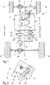
- a motor vehicle 1 with all-wheel drive is suitable for use in the agricultural and construction industries and / or for civil protection and disaster tasks and is provided with a drive unit 2, which is driven between a first wheel axle 3 - rear axle and a second wheel axle 4 - front axle is which wheel axles 3 and 4 are arranged at a distance from one another in the vehicle longitudinal direction BB.
- the drive unit 2 has an internal combustion engine 5 of the reciprocating piston type with an at least one horizontally lying crankshaft 6 of a crankshaft system 7 that extends in the vehicle longitudinal direction B-B.
- the crankshaft 6 acts on a continuously variable transmission system 8, type CVT (Continuously Variable Transmission), which drives wheels 9, 10 and 11, 12 of the first wheel axle 3 and the second wheel axle 4.
- CVT Continuous Variable Transmission
- the crankshaft 6 of the crankshaft system 7 is rotated by reciprocating pistons 13, 14 of the internal combustion engine 5 and interacts with a first pair of conical disks 15 of the transmission system 8, which cooperates with a first differential 18 of the first wheel axle 4 via a first drive shaft 17.
- the first pair of conical disks 15 is under Mediation of an endless link 19 in the form of a thrust link belt with a second pair of conical disks 20 of the transmission system 8 in operative connection, which, with the interposition of a second drive shaft 22, influences a second differential 23 of the second wheel axle 4.
- the crankshaft system 7 of the internal combustion engine 5 comprises two parallel crankshafts, namely the crankshaft 6 already cited and a further crankshaft 24 ( Fig. 3 ). Both crankshafts 6 and 24 work together by means of synchronization gears 25 and 26 in such a way that the crankshafts 6 and 24 rotate in opposite directions.
- the crankshafts 6 and 24 are driven by connecting rods 27 and 28 which are each coupled to one of the reciprocating pistons 13 and 14.
- the reciprocating piston 13 moves back and forth in a bore 29 of a cylinder crankcase 30, the cylinder crankcase 30 being covered by a cylinder head 31 which receives gas exchange valves 34 and 35 actuated by camshafts 32, 33.
- This internal combustion engine 5 is particularly efficient in that it works in the diesel process and is also provided with an exhaust gas turbocharger device, optionally also with direct injection (system common rail), not shown.
- An internal combustion engine of this type goes out of the DE 10 2011 104 496 B4 forth.
- crankshafts 6 or 24 of the crankshaft system 7 of the internal combustion engine 5 is driven toward the first pair of conical disks 15 from a first end region 36 of the crankshaft system 7.
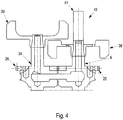
- Flywheels 38 and 39 are provided on the latter at the second end region 37 of the crankshaft system 7 or the crankshafts 6 and 24 spaced apart from the first end region 36. In the axial direction of crankshafts 6 and 24, flywheels 38 and 39 are offset from one another and overlap in regions.
- An extension 40 is provided on at least the crankshaft 6 and serves as a power take-off shaft 41 for driving auxiliary units.
- the first and second drive shafts 17 and 22 are aligned in the vehicle longitudinal direction BB and run at a symmetrical or asymmetrical distance from a central longitudinal plane CC of the motor vehicle 1.
- the second drive shaft 22 extends below an outer housing wall 42 of the cylinder crankcase 30 of the internal combustion engine 5, with the second drive shaft 22 on the cylinder crankcase 30 or the housing wall 42 the latter or the internal combustion engine 5 obliquely, that is to say runs at an acute angle ⁇ to a horizontal 43.
- a drive shaft 44 into which a clutch 45 is connected is effective between the first end region 36 and the first pair of conical disks.
- the clutch 45 is formed by a clutch, a centrifugal clutch or the like.
Landscapes
- Engineering & Computer Science (AREA)
- Chemical & Material Sciences (AREA)
- Combustion & Propulsion (AREA)
- Transportation (AREA)
- Mechanical Engineering (AREA)
- Arrangement Of Transmissions (AREA)
- Arrangement Or Mounting Of Propulsion Units For Vehicles (AREA)
Description
- Die Erfindung bezieht sich auf eine Antriebseinheit für ein Kraftfahrzeug mit Allradantrieb, das z.B. zum Einsatz in der Agrar- und Bauwirtschafft und/oder für Zivilschutz- und Katastrophenaufgaben ausgebildet ist, nach dem Oberbegriff des Patentanspruchs 1.
- Es ist ein Kraftfahrzeug von hoher Geländegängigkeit bekannt,
US 3,331,464 . Zum Antrieb des Kraftfahrzeugs dient eine Brennkraftmaschine, die zwischen einer Vorderachse und einer Hinterachse angeordnet ist. Die eine Fliehkraftkupplung aufweisende Brennkraftmaschine wirkt mit einer quer zur Fahrzeuglängsrichtung verlaufenden Antriebswelle und einem Winkeltreib auf ein erstes Kegelscheibenpaar eines CVT-Getriebes ein. Dessen zweites Kegelscheibenpaar ist mit einem Getriebe verbunden, das einerseits mit der Hinterachse und andererseits mit der Vorderachse in Wirkverbindung steht, so dass das Kraftfahrzeug vierradgetrieben ist. - Aus der
US 2,915,133 geht ein Kraftfahrzeug der Sportwagen- bzw. Rennwagengattung hervor, das zwischen den Radachsen eine Brennkraftmaschine aufweist. Die nahe einer Vorderachse eigebaute Brennkraftmaschine verfügt über V-förmig angeordnete Zylinderreihen, die zur rechten Fahrzeugseite hin schräg verlaufen. Eine in Längsrichtung des Kraftfahrzeugs sich erstreckende Kurbelwelle der Brennkraftmaschine treibt unter Vermittlung von Getrieben die Vorderachse und die Hinterachse an. - Die
DE 2 160 430 befasst sich mit einem nach Art eines Traktors ausgebildeten Geräteträger. Eine Brennkraftmaschine treibt die Vorderräder und die Hinterräder an. Dabei ist eine Brennkraftmaschine zwischen einer Vorderachse und einer Hinterachse eingebaut und erste Kardanwelle verbindet die Vorderachse mit der Hinterachse. Eine zweite Kardanwelle erstreckt sich zwischen einem mit der Brennkraftmaschine zusammenwirkenden Getriebe und der Hinterachse. Beide Kardanwellen sind zur Erzielung einer definierten Bodenfreiheit des Geräteträgers seitlich an einem Motorblock der Brennkraftmaschine vorbeigeführt. - Die
JP H02 200526 A - Aufgabe der Erfindung ist es eine Antriebseinheit für ein Kraftfahrzeug mit Allradantrieb zu konzipieren, durch die ein Kraftfahrzeug vielfältig einsetzbar ist. Dabei sollte aber auch sichergestellt werden, dass die Brennkraftmaschine und Getriebeeinrichtung mit Antriebswellen für Räder von Antriebsachsen der Antriebseinheit sich zum einen mit vertretbarem Aufwand umsetzen lassen und zum anderen durch gute Funktion auszeichnen.
- Nach der Erfindung wird diese Aufgabe durch die Merkmale des Patentanspruchs 1 gelöst. Weitere, die Erfindung ausgestaltende Merkmale sind in den Unteransprüchen enthalten.
- Die mit der Erfindung hauptsächlich erzielten Vorteile sind darin zu sehen, dass das Zusammenwirken der Kurbelwelle des Kurbelwellensystems der Brennkraftmaschine mit dem ersten Kegelscheibenpaar sowie der Antrieb des zweiten Kegelscheibenpaars durch das erste Kegelscheibenpaar wie auch die Beeinflussung der Antriebsachsen durch das zweite Kegelscheibenpaar vorbildliche technische Voraussetzungen für die Antriebseinheit schaffen. Diese zeichnen sich einerseits durch einfache Realisierbarkeit aus. Anderseits ermöglichen sie auch, dass ein so gestaltetes Kraftfahrzeug gerade für den Einsatz in der Agrar- und Bauwirtschaft aber auch bei Zivilschutz- und Katastrophenaufgaben hervorragende Dienste tut ist.
- Unterstützt wird dieses Allradkonzept durch die Brennkraftmaschine mit dem zwei Kurbelwellen umfassenden Kurbelwellensystem, welche Kurbelwellen mittels Synchronisationszahnräder in entgegengesetzte Richtungen rotieren. Diese Bauweise bewirkt ausgezeichnete Betriebseigenschaften der Brennkraftmaschine, und zwar bezüglich Laufruhe, Verbrauch und Standfestigkeit. Baulich geschickt gelöst ist, dass der Abtrieb des Kurbelwellensystems hin zum ersten Kegelscheibenpaar von dem ersten Endbereich des Kurbelwellensystems aus erfolgt und dass im zweiten Endbereich des Kurbelwellensystems die Kurbelwellen mit Schwungrädern versehen sind. Hervorzuheben ist in diesem Zusammenhang, dass an wenigstens einer Kurbelwelle eine Zapfwelle zum Antrieb von Nebenaggregaten vorgesehen ist.
- Sinnreich ist, dass die zweite Antriebswelle unterhalb eines Zylinderkurbelgehäuses der Brennkraftmaschine verläuft und dass die Brennkraftmaschine zur Vorbeiführung der zweiten Antriebswelle an dem Zylinderkurbelgehäuse schräg zu einer Horizontalen verläuft.
- Eine durchdachte Konstruktion ist, dass in eine Triebwelle zwischen dem ersten Endbereich des Kurbelwellensystems und dem ersten Kegelscheibenpaar eine Kupplung geschaltet ist. Sie kann durch eine Schaltkupplung, eine Fliehkraftkupplung oder dgl. gebildet werden. Schließlich ist gestalterisch vorteilhaft, dass die Drehachsen der Kurbelwellen sowie der ersten und zweiten Antriebswellen in Fahrzeuglängsrichtung ausgerichtet sind.
- In der Zeichnung wird ein Ausführungsbespiel gezeigt, das nachstehend näher beschrieben wird.
- Es zeigen
-
Fig. 1 eine schematische Ansicht von oben auf die Antriebseinheit, eingebaut in ein Kraftfahrzeug mit Allradantrieb, -
Fig. 2 einen schematischen Schnitt etwa nach der Linie II-II derFig. 1 , -
Fig. 3 einen schematischen Querschnitt durch die Brennkraftmaschine z.B. nachFig. 2 , -
Fig. 4 eine Ansicht in Pfeilrichtung A derFig. 1 . - Ein Kraftfahrzeug 1 mit Allradantrieb ist zum Einsatz in der Agrar- und Bauwirtschaft und/oder für Zivilschutz- und Katastrophenaufgaben geeignet und ist mit einer Antriebseinheit 2 versehen, die zwischen einer ersten Radachse 3 -Hinterachse- und einer zweiten Radachse 4 -Vorderachse- angetrieben wirksam ist, welche Radachsen 3 und 4 in Fahrzeuglängsrichtung B-B mit Abstand zueinander angeordnet sind. Die Antriebseinheit 2 weist eine Brennkraftmaschine 5 der Hubkolbenbauart mit einem zumindest eine horizontal liegende in Fahrzeuglängsrichtung B-B sich erstreckende Kurbelwelle 6 eines Kurbelwellensystems 7 auf. Die Kurbelwelle 6 wirkt auf ein stufenloses Getriebesystem 8, Bauart CVT (Continuously Variable Transmission) ein, die Räder 9, 10 und 11,12 der ersten Radachse 3 und der zweiten Radachse 4 antreibt.
- Die Kurbelwelle 6 des Kurbelwellensystems 7 wird von Hubkolben 13, 14 der Brennkraftmaschine 5 in Drehbewegung versetzt und wirkt mit einem ersten Kegelscheibenpaar 15 des Getriebesystems 8 zusammen, das über eine erste Antriebswelle 17 mit einem ersten Differential 18 der ersten Radachse 4 zusammenwirkt. Das erste Kegelscheibenpaar 15 steht unter Vermittlung eines Endlosgliedes 19 in Gestalt eines Schubgliederbands mit einem zweiten Kegelscheibenpaar 20 des Getriebesystems 8 in Wirkverbindung, das unter Zwischenschaltung einer zweiten Antriebswelle 22 ein zweites Differential 23 der zweiten Radachse 4 beeinflusst.
- Das Kurbelwellensystem 7 der Brennkraftmaschine 5 umfasst zwei parallele Kurbelwellen, und zwar die bereits zitierte Kurbelwelle 6 und eine weitere Kurbelwelle 24 (
Fig. 3 ). Beide Kurbelwellen 6 und 24 arbeiten mittels Synchronisationszahnräder 25 und 26 zusammen, dergestalt, dass die Kurbelwellen 6 und 24 sich in entgegengesetzten Richtungen drehen. Angetrieben werden die Kurbelwellen 6 und 24 von Pleueln 27 und 28 die jeweils mit einem der Hubkolben 13 und 14 gekoppelt sind. Der Hubkolben 13 bewegt sich ich in einer Bohrung 29 eines Zylinderkurbelgehäuses 30 hin und her, wobei das Zylinderkurbelgehäuse 30 von einem Zylinderkopf 31 abgedeckt, der von Nockenwellen 32, 33 betätigte Gaswechselventile 34 und 35 aufnimmt. Besonders effizient ist diese Brennkraftmaschine 5 dadurch, dass sie im Dieselverfahren arbeitet und mit einer Abgasturboladereinrichtung gegebenenfalls auch mit Direkteinspritzung (System Common Rail) -nicht gezeigt- versehen ist. Eine Brennkraftmaschine dieser Art geht aus derDE 10 2011 104 496 B4 hervor. - Der Abtrieb einer der Kurbelwellen 6 oder 24 des Kurbelwellensystems 7 der Brennkraftmaschine 5 hin zum ersten Kegelscheibenpaar 15 erfolgt von einem ersten Endbereich 36 des besagten Kurbelwellensystems 7 aus. Am vom ersten Endbereich 36 beabstandeten zweiten Endbereich 37 der Kurbelwellensystem 7 bzw. der Kurbelwellen 6 und 24 sind an letzteren Schwungräder 38 und 39 vorgesehen. In axialer Richtung der Kurbelwellen 6 und 24 sind die Schwungräder 38 und 39 versetzt zueinander angeordnet und sie überlappen sich bereichsweise. An zumindest der Kurbelwelle 6 ist eine Verlängerung 40 vorgesehen, die als Zapfwelle 41 zum Antrieb von Nebenaggregaten dient.
- Die erste und zweite Antriebswelle 17 und 22 sind in Fahrzeuglängsrichtung B-B ausgerichtet und verlaufen mit symmetrischem oder asymmetrischem Abstand zu einer Mittellängsebene C-C des Kraftfahrzeugs 1. Die zweite Antriebswelle 22 erstreckt sich unterhalb einer äußeren Gehäusewand 42 des Zylinderkurbelgehäuses 30 der Brennkraftmaschine 5, wobei zur Vorbeiführung der zweiten Antriebswelle 22 an dem Zylinderkurbelgehäuse 30 bzw. der Gehäusewand 42 letztere bzw. die Brennkraftmaschine 5 schräg, will heißen im spitzen Winkel α zu einer Horizontalen 43 verläuft. Schließlich ist zwischen dem ersten Endbereich 36 und dem ersten Kegelscheibenpaar eine Triebwelle 44 wirksam, in die eine Kupplung 45 geschaltete ist. Die Kupplung 45 wird durch Schaltkupplung, Fliehkraftkupplung oder dgl. gebildet.
-
- 1
- Kraftfahrzeug
- 2
- Antriebseinheit
- 3
- erste Radachse
- 4
- zweite Radachse
- 5
- Brennkraftmaschine
- 6
- Kurbelwelle
- 7
- Kurbelwellensystem
- 8
- Getriebesystem
- 9
- Rad, erste Radachse
- 10
- Rad, erste Radachse
- 11
- Rad, zweite Radachse
- 12
- Rad, zweite Radachse
- 13
- Hubkolben
- 14
- Hubkolben
- 15
- erstes Kegelscheibenpaar
- 17
- erste Antriebswelle
- 18
- erstes Differential
- 19
- Endlosglied
- 20
- zweites Kegelscheibenpaar
- 22
- zweite Antriebswelle
- 23
- zweites Differential
- 24
- weitere Kurbelwelle
- 25
- Synchronisationszahnrad
- 26
- Synchronisationszahnrad
- 27
- Pleuel
- 28
- Pleuel
- 29
- Bohrung
- 30
- Zylinderkurbelgehäuse
- 31
- Zylinderkopf
- 32
- Nockenwelle
- 33
- Nockenwelle
- 34
- Gaswechselventil
- 35
- Gaswechselventil
- 36
- erster Endbereich
- 37
- zweiter Endbereich
- 38
- Schwungrad
- 39
- Schwungrad
- 40
- Verlängerung
- 41
- Zapfwelle
- 42
- Gehäusewand
- α
- Winkel
- 43
- Horizontale
- 44
- Triebwelle
- 45
- Kupplung
Claims (7)
- Kraftfahrzeug (1) mit Allradantrieb, wobei das Kraftfahrzeug (1) aufweist:- eine als Hinterachse eingerichtete erste Radachse (3) mit daran angeordneten Rädern (9, 10),- eine von der ersten Radachse (3) in Längsrichtung des Kraftfahrzeugs (1) beabstandet angeordnete, als Vorderachse eingerichtete zweite Radachse (4) mit daran angeordneten Rädern (11, 12),- eine zwischen der ersten Radachse (3) und der zweiten Radachse (4) angeordnete Antriebseinheit (2) mit einer Brennkraftmaschine (5), wobei die Brennkraftmaschine (5) wenigstens eine horizontal ausgerichtete, sich in Längsrichtung des Kraftfahrzeugs (1) erstreckende Kurbelwelle (6) aufweist, und- ein mit der Kurbelwelle (6) der Antriebseinheit (2) zusammenwirkendes, die Räder (9, 10) der ersten Radachse (3) und die Räder (11, 12) der zweiten Radachse (4) antreibendes stufenloses Getriebesystem,
wobei- die Kurbelwelle (6) von wenigstens einem Hubkolben (13, 14) der Brennkraftmaschine (5) in Drehbewegung versetzt wird und mit einem ersten Kegelscheibenpaar (15) des Getriebesystems zusammenwirkt,- das erste Kegelscheibenpaar (15) des Getriebesystems unter Vermittlung eines Endlosglieds (19) mit einem zweiten Kegelscheibenpaar (20) des Getriebesystems in Wirkverbindung steht,- das zweite Kegelscheibenpaar (20) über eine erste Antriebswelle (17) mit einem ersten Differential (18) der ersten Radachse (3) und über eine zweite Antriebswelle (22) mit einem zweiten Differential (23) der zweiten Radachse (4) verbunden ist,dadurch gekennzeichnet, dass
sich die zweite Antriebswelle (22) unterhalb einer äußeren Gehäusewand (42) des den wenigstens einen Hubkolben (13, 14) aufnehmenden Zylinderkurbelgehäuses (30) der Brennkraftmaschine (5) erstreckt, wobei die äußere Gehäusewand (42) in einem spitzen Winkel α schräg zur Horizontalen (43) verläuft. - Kraftfahrzeug (1) nach Anspruch 1, dadurch gekennzeichnet, dass das Kurbelwellensystem der (7) Brennkraftmaschine (5) zwei parallele Kurbelwellen (6, 24) umfasst, die von dem wenigstens einen Hubkolben (13, 14) beeinflusst werden, wobei die Kurbelwellen (6, 24) mittels Synchronisationszahnräder (25, 26) zusammenarbeiten und in entgegengesetzte Richtungen rotieren.
- Kraftfahrzeug (1) nach Anspruch 2, dadurch gekennzeichnet, dass der Abtrieb des Kurbelwellensystems (7) hin zum ersten Kegelscheibenpaar (15) von einem ersten Endbereich (36) des Kurbelwellensystems (7) aus erfolgt.
- Kraftfahrzeug (1) nach Anspruch 3, dadurch gekennzeichnet, dass in einem zweiten Endbereich (37) des Kurbelwellensystems (7) die Kurbelwellen (6) mit Schwungrädern (38, 39) versehen sind.
- Kraftfahrzeug (1) nach Anspruch 4, dadurch gekennzeichnet, dass benachbart des zweiten Endbereichs (37) in Verlängerung wenigstens einer der Kurbelwellen (6, 24) des Kurbelwellensystems (7) eine Zapfwelle (41) vorgesehen ist.
- Kraftfahrzeug (1) nach Anspruch 3, dadurch gekennzeichnet, dass zwischen dem ersten Endbereich (36) des Kurbelwellensystems (7) und dem ersten Kegelscheibenpaar (15) eine Kupplung (45) in eine Triebwelle geschaltet ist.
- Kraftfahrzeug (1) nach Anspruch 6, dadurch gekennzeichnet, dass die Kupplung (45) durch eine Schaltkupplung oder Fliehkraftkupplung gebildet ist.
Applications Claiming Priority (2)
| Application Number | Priority Date | Filing Date | Title |
|---|---|---|---|
| DE102016012710 | 2016-10-25 | ||
| DE102017007552.2A DE102017007552A1 (de) | 2016-10-25 | 2017-08-10 | Antriebseinheit für ein Kraftfahrzeug |
Publications (2)
| Publication Number | Publication Date |
|---|---|
| EP3315342A1 EP3315342A1 (de) | 2018-05-02 |
| EP3315342B1 true EP3315342B1 (de) | 2020-04-08 |
Family
ID=60185957
Family Applications (1)
| Application Number | Title | Priority Date | Filing Date |
|---|---|---|---|
| EP17001746.1A Active EP3315342B1 (de) | 2016-10-25 | 2017-10-24 | Antriebseinheit für ein kraftfahrzeug |
Country Status (1)
| Country | Link |
|---|---|
| EP (1) | EP3315342B1 (de) |
Family Cites Families (10)
| Publication number | Priority date | Publication date | Assignee | Title |
|---|---|---|---|---|
| US2915133A (en) | 1954-07-02 | 1959-12-01 | Daimler Benz Ag | Vehicle having four-wheel drive with offset flywheel |
| US3331464A (en) | 1965-01-08 | 1967-07-18 | Doorne S Automobielfabriek N V | Four wheel belt variable transmission drive |
| CH516901A (de) | 1970-12-16 | 1971-12-31 | Schilter & Co Maschf | Geräteträger |
| DE3739692A1 (de) * | 1987-11-24 | 1989-06-08 | Fendt & Co Xaver | Kupplungsanordnung in einem antrieb fuer nutzfahrzeuge |
| JPH02200526A (ja) * | 1989-01-31 | 1990-08-08 | Suzuki Motor Co Ltd | 4輪駆動車 |
| US5527225A (en) * | 1992-12-29 | 1996-06-18 | Dana Corporation | Full time four-wheel drive system |
| RU2089739C1 (ru) * | 1993-03-04 | 1997-09-10 | Черногоров Анатолий Дмитриевич | Двигатель внутреннего сгорания с самовоспламенением (с впрыском топлива) со сверхвысокими (более 19) регулируемыми степенями сжатия |
| GB2349417A (en) * | 1999-04-26 | 2000-11-01 | Brian Mawdsley | I.c. engine with piston connected by two con-rods to a pair of contra-rotating crankshafts |
| US20070144283A1 (en) * | 2005-11-30 | 2007-06-28 | Toshiyuki Hasegawa | Power Transmission Apparatus |
| DE102011104496B4 (de) | 2011-06-17 | 2014-02-13 | Neander Motors Ag | Brennkraftmaschine der Hubkolbenbauart |
-
2017
- 2017-10-24 EP EP17001746.1A patent/EP3315342B1/de active Active
Non-Patent Citations (1)
| Title |
|---|
| None * |
Also Published As
| Publication number | Publication date |
|---|---|
| EP3315342A1 (de) | 2018-05-02 |
Similar Documents
| Publication | Publication Date | Title |
|---|---|---|
| DE10059101B4 (de) | Antriebssystem | |
| DE102018209905A1 (de) | Raupenantriebssystem für ein Raupenarbeitsfahrzeug | |
| WO2018001619A1 (de) | Getriebe für ein kraftfahrzeug, sowie antriebsstrang für ein kraftfahrzeug | |
| DE102017007552A1 (de) | Antriebseinheit für ein Kraftfahrzeug | |
| DE102006038358B4 (de) | Achsantriebseinheit für einen Antriebsstrang | |
| DE102005049706A1 (de) | Getriebevorrichtung | |
| EP1321327A2 (de) | Längs eingebauter Antriebsstrang | |
| DE102016206213A1 (de) | Anordnung für Leistungsübertragungseinheit (PTU) mit Zylinder | |
| DE102011018865B4 (de) | Antriebsvorrichtung für ein front-, heck- oder allradgetriebenes Kraftfahrzeug | |
| DE102022003203B4 (de) | Hybridantriebssystem für ein Kraftfahrzeug, insbesondere für einen Kraftwagen, sowie Kraftfahrzeug | |
| DE2948195A1 (de) | Getriebe als hauptantrieb fuer ein von einer verbrennungskraftmaschine angetriebenes fahrzeug | |
| DE102014220028B4 (de) | Getriebevorrichtung mit Leistungsverzweigung | |
| DE102019205987B4 (de) | Elektrischer Achsantrieb für ein Fahrzeug | |
| WO2007138005A1 (de) | Getriebeeinheit zur führung eines antriebsmomentes von einer antriebswelle auf zwei abtriebswellen | |
| DE102007019008A1 (de) | Verfahren zur Herstellung einer gesenkgeschmiedeten Ausgleichswelle | |
| DE102016013288A1 (de) | Kraftfahrzeug für vielfältigen Einsatz | |
| DE3119362C2 (de) | Vierzylinder-Brennkraftmaschine mit einem Massenausgleich zweiter Ordnung | |
| EP3315342A1 (de) | Antriebseinheit für ein kraftfahrzeug | |
| DE19849457C2 (de) | Kreuzgelenk | |
| EP3546269A2 (de) | Kraftfahrzeug mit allradantrieb | |
| DE102013219945B4 (de) | Anordnung für einen Verbrennungsmotor eines Kraftfahrzeuges umfassend eine erste Pumpe, eine Ausgleichswelle und eine zweite Pumpe sowie Verfahren zur Montage einer Ausgleichswelle in einem Gehäuse | |
| DE3319523C2 (de) | Hinterachsantrieb insbesondere für Kraftfahrzeuge, mit einem Differentialgetriebe und einem stufenlosen Wechselgetriebe | |
| EP2726313B1 (de) | Antriebsstranganordnung für kraftfahrzeug und bausatz für antriebsstränge von kraftfahrzeugen unterschiedlicher art | |
| EP0365811B1 (de) | Arbeitsfahrzeug mit geringer Bodenfreiheit | |
| EP1233211A1 (de) | Ausgleichsgetriebe mit einer Schmiervorrichtung |
Legal Events
| Date | Code | Title | Description |
|---|---|---|---|
| PUAI | Public reference made under article 153(3) epc to a published international application that has entered the european phase |
Free format text: ORIGINAL CODE: 0009012 |
|
| STAA | Information on the status of an ep patent application or granted ep patent |
Free format text: STATUS: THE APPLICATION HAS BEEN PUBLISHED |
|
| AK | Designated contracting states |
Kind code of ref document: A1 Designated state(s): AL AT BE BG CH CY CZ DE DK EE ES FI FR GB GR HR HU IE IS IT LI LT LU LV MC MK MT NL NO PL PT RO RS SE SI SK SM TR |
|
| AX | Request for extension of the european patent |
Extension state: BA ME |
|
| STAA | Information on the status of an ep patent application or granted ep patent |
Free format text: STATUS: REQUEST FOR EXAMINATION WAS MADE |
|
| 17P | Request for examination filed |
Effective date: 20190208 |
|
| RBV | Designated contracting states (corrected) |
Designated state(s): AL AT BE BG CH CY CZ DE DK EE ES FI FR GB GR HR HU IE IS IT LI LT LU LV MC MK MT NL NO PL PT RO RS SE SI SK SM TR |
|
| GRAP | Despatch of communication of intention to grant a patent |
Free format text: ORIGINAL CODE: EPIDOSNIGR1 |
|
| STAA | Information on the status of an ep patent application or granted ep patent |
Free format text: STATUS: GRANT OF PATENT IS INTENDED |
|
| GRAS | Grant fee paid |
Free format text: ORIGINAL CODE: EPIDOSNIGR3 |
|
| INTG | Intention to grant announced |
Effective date: 20200204 |
|
| GRAA | (expected) grant |
Free format text: ORIGINAL CODE: 0009210 |
|
| STAA | Information on the status of an ep patent application or granted ep patent |
Free format text: STATUS: THE PATENT HAS BEEN GRANTED |
|
| AK | Designated contracting states |
Kind code of ref document: B1 Designated state(s): AL AT BE BG CH CY CZ DE DK EE ES FI FR GB GR HR HU IE IS IT LI LT LU LV MC MK MT NL NO PL PT RO RS SE SI SK SM TR |
|
| REG | Reference to a national code |
Ref country code: CH Ref legal event code: EP Ref country code: AT Ref legal event code: REF Ref document number: 1253912 Country of ref document: AT Kind code of ref document: T Effective date: 20200415 |
|
| REG | Reference to a national code |
Ref country code: DE Ref legal event code: R096 Ref document number: 502017004577 Country of ref document: DE |
|
| REG | Reference to a national code |
Ref country code: IE Ref legal event code: FG4D Free format text: LANGUAGE OF EP DOCUMENT: GERMAN |
|
| REG | Reference to a national code |
Ref country code: NL Ref legal event code: FP |
|
| REG | Reference to a national code |
Ref country code: SE Ref legal event code: TRGR |
|
| REG | Reference to a national code |
Ref country code: FI Ref legal event code: FGE |
|
| REG | Reference to a national code |
Ref country code: NO Ref legal event code: T2 Effective date: 20200408 |
|
| REG | Reference to a national code |
Ref country code: LT Ref legal event code: MG4D |
|
| PG25 | Lapsed in a contracting state [announced via postgrant information from national office to epo] |
Ref country code: PT Free format text: LAPSE BECAUSE OF FAILURE TO SUBMIT A TRANSLATION OF THE DESCRIPTION OR TO PAY THE FEE WITHIN THE PRESCRIBED TIME-LIMIT Effective date: 20200817 Ref country code: GR Free format text: LAPSE BECAUSE OF FAILURE TO SUBMIT A TRANSLATION OF THE DESCRIPTION OR TO PAY THE FEE WITHIN THE PRESCRIBED TIME-LIMIT Effective date: 20200709 Ref country code: LT Free format text: LAPSE BECAUSE OF FAILURE TO SUBMIT A TRANSLATION OF THE DESCRIPTION OR TO PAY THE FEE WITHIN THE PRESCRIBED TIME-LIMIT Effective date: 20200408 Ref country code: IS Free format text: LAPSE BECAUSE OF FAILURE TO SUBMIT A TRANSLATION OF THE DESCRIPTION OR TO PAY THE FEE WITHIN THE PRESCRIBED TIME-LIMIT Effective date: 20200808 |
|
| REG | Reference to a national code |
Ref country code: ES Ref legal event code: FG2A Ref document number: 2791475 Country of ref document: ES Kind code of ref document: T3 Effective date: 20201104 |
|
| PG25 | Lapsed in a contracting state [announced via postgrant information from national office to epo] |
Ref country code: BG Free format text: LAPSE BECAUSE OF FAILURE TO SUBMIT A TRANSLATION OF THE DESCRIPTION OR TO PAY THE FEE WITHIN THE PRESCRIBED TIME-LIMIT Effective date: 20200708 Ref country code: HR Free format text: LAPSE BECAUSE OF FAILURE TO SUBMIT A TRANSLATION OF THE DESCRIPTION OR TO PAY THE FEE WITHIN THE PRESCRIBED TIME-LIMIT Effective date: 20200408 Ref country code: RS Free format text: LAPSE BECAUSE OF FAILURE TO SUBMIT A TRANSLATION OF THE DESCRIPTION OR TO PAY THE FEE WITHIN THE PRESCRIBED TIME-LIMIT Effective date: 20200408 Ref country code: LV Free format text: LAPSE BECAUSE OF FAILURE TO SUBMIT A TRANSLATION OF THE DESCRIPTION OR TO PAY THE FEE WITHIN THE PRESCRIBED TIME-LIMIT Effective date: 20200408 |
|
| PG25 | Lapsed in a contracting state [announced via postgrant information from national office to epo] |
Ref country code: AL Free format text: LAPSE BECAUSE OF FAILURE TO SUBMIT A TRANSLATION OF THE DESCRIPTION OR TO PAY THE FEE WITHIN THE PRESCRIBED TIME-LIMIT Effective date: 20200408 |
|
| REG | Reference to a national code |
Ref country code: DE Ref legal event code: R097 Ref document number: 502017004577 Country of ref document: DE |
|
| PG25 | Lapsed in a contracting state [announced via postgrant information from national office to epo] |
Ref country code: CZ Free format text: LAPSE BECAUSE OF FAILURE TO SUBMIT A TRANSLATION OF THE DESCRIPTION OR TO PAY THE FEE WITHIN THE PRESCRIBED TIME-LIMIT Effective date: 20200408 Ref country code: IT Free format text: LAPSE BECAUSE OF FAILURE TO SUBMIT A TRANSLATION OF THE DESCRIPTION OR TO PAY THE FEE WITHIN THE PRESCRIBED TIME-LIMIT Effective date: 20200408 Ref country code: RO Free format text: LAPSE BECAUSE OF FAILURE TO SUBMIT A TRANSLATION OF THE DESCRIPTION OR TO PAY THE FEE WITHIN THE PRESCRIBED TIME-LIMIT Effective date: 20200408 Ref country code: EE Free format text: LAPSE BECAUSE OF FAILURE TO SUBMIT A TRANSLATION OF THE DESCRIPTION OR TO PAY THE FEE WITHIN THE PRESCRIBED TIME-LIMIT Effective date: 20200408 Ref country code: SM Free format text: LAPSE BECAUSE OF FAILURE TO SUBMIT A TRANSLATION OF THE DESCRIPTION OR TO PAY THE FEE WITHIN THE PRESCRIBED TIME-LIMIT Effective date: 20200408 Ref country code: DK Free format text: LAPSE BECAUSE OF FAILURE TO SUBMIT A TRANSLATION OF THE DESCRIPTION OR TO PAY THE FEE WITHIN THE PRESCRIBED TIME-LIMIT Effective date: 20200408 |
|
| PLBE | No opposition filed within time limit |
Free format text: ORIGINAL CODE: 0009261 |
|
| STAA | Information on the status of an ep patent application or granted ep patent |
Free format text: STATUS: NO OPPOSITION FILED WITHIN TIME LIMIT |
|
| PG25 | Lapsed in a contracting state [announced via postgrant information from national office to epo] |
Ref country code: SK Free format text: LAPSE BECAUSE OF FAILURE TO SUBMIT A TRANSLATION OF THE DESCRIPTION OR TO PAY THE FEE WITHIN THE PRESCRIBED TIME-LIMIT Effective date: 20200408 Ref country code: PL Free format text: LAPSE BECAUSE OF FAILURE TO SUBMIT A TRANSLATION OF THE DESCRIPTION OR TO PAY THE FEE WITHIN THE PRESCRIBED TIME-LIMIT Effective date: 20200408 |
|
| 26N | No opposition filed |
Effective date: 20210112 |
|
| PG25 | Lapsed in a contracting state [announced via postgrant information from national office to epo] |
Ref country code: SI Free format text: LAPSE BECAUSE OF FAILURE TO SUBMIT A TRANSLATION OF THE DESCRIPTION OR TO PAY THE FEE WITHIN THE PRESCRIBED TIME-LIMIT Effective date: 20200408 |
|
| REG | Reference to a national code |
Ref country code: CH Ref legal event code: PL Ref country code: FI Ref legal event code: MAE |
|
| PG25 | Lapsed in a contracting state [announced via postgrant information from national office to epo] |
Ref country code: MC Free format text: LAPSE BECAUSE OF FAILURE TO SUBMIT A TRANSLATION OF THE DESCRIPTION OR TO PAY THE FEE WITHIN THE PRESCRIBED TIME-LIMIT Effective date: 20200408 Ref country code: LU Free format text: LAPSE BECAUSE OF NON-PAYMENT OF DUE FEES Effective date: 20201024 |
|
| REG | Reference to a national code |
Ref country code: BE Ref legal event code: MM Effective date: 20201031 |
|
| PG25 | Lapsed in a contracting state [announced via postgrant information from national office to epo] |
Ref country code: FI Free format text: LAPSE BECAUSE OF NON-PAYMENT OF DUE FEES Effective date: 20201024 |
|
| PG25 | Lapsed in a contracting state [announced via postgrant information from national office to epo] |
Ref country code: LI Free format text: LAPSE BECAUSE OF NON-PAYMENT OF DUE FEES Effective date: 20201031 Ref country code: BE Free format text: LAPSE BECAUSE OF NON-PAYMENT OF DUE FEES Effective date: 20201031 Ref country code: CH Free format text: LAPSE BECAUSE OF NON-PAYMENT OF DUE FEES Effective date: 20201031 |
|
| PG25 | Lapsed in a contracting state [announced via postgrant information from national office to epo] |
Ref country code: IE Free format text: LAPSE BECAUSE OF NON-PAYMENT OF DUE FEES Effective date: 20201024 |
|
| PG25 | Lapsed in a contracting state [announced via postgrant information from national office to epo] |
Ref country code: TR Free format text: LAPSE BECAUSE OF FAILURE TO SUBMIT A TRANSLATION OF THE DESCRIPTION OR TO PAY THE FEE WITHIN THE PRESCRIBED TIME-LIMIT Effective date: 20200408 Ref country code: MT Free format text: LAPSE BECAUSE OF FAILURE TO SUBMIT A TRANSLATION OF THE DESCRIPTION OR TO PAY THE FEE WITHIN THE PRESCRIBED TIME-LIMIT Effective date: 20200408 Ref country code: CY Free format text: LAPSE BECAUSE OF FAILURE TO SUBMIT A TRANSLATION OF THE DESCRIPTION OR TO PAY THE FEE WITHIN THE PRESCRIBED TIME-LIMIT Effective date: 20200408 |
|
| PG25 | Lapsed in a contracting state [announced via postgrant information from national office to epo] |
Ref country code: MK Free format text: LAPSE BECAUSE OF FAILURE TO SUBMIT A TRANSLATION OF THE DESCRIPTION OR TO PAY THE FEE WITHIN THE PRESCRIBED TIME-LIMIT Effective date: 20200408 |
|
| PGFP | Annual fee paid to national office [announced via postgrant information from national office to epo] |
Ref country code: NL Payment date: 20221021 Year of fee payment: 6 Ref country code: FR Payment date: 20221021 Year of fee payment: 6 |
|
| PGFP | Annual fee paid to national office [announced via postgrant information from national office to epo] |
Ref country code: SE Payment date: 20221021 Year of fee payment: 6 Ref country code: NO Payment date: 20221019 Year of fee payment: 6 Ref country code: GB Payment date: 20221019 Year of fee payment: 6 Ref country code: ES Payment date: 20221102 Year of fee payment: 6 Ref country code: DE Payment date: 20221117 Year of fee payment: 6 |
|
| REG | Reference to a national code |
Ref country code: AT Ref legal event code: MM01 Ref document number: 1253912 Country of ref document: AT Kind code of ref document: T Effective date: 20221024 |
|
| PG25 | Lapsed in a contracting state [announced via postgrant information from national office to epo] |
Ref country code: AT Free format text: LAPSE BECAUSE OF NON-PAYMENT OF DUE FEES Effective date: 20221024 |
|
| REG | Reference to a national code |
Ref country code: DE Ref legal event code: R119 Ref document number: 502017004577 Country of ref document: DE |
|
| REG | Reference to a national code |
Ref country code: SE Ref legal event code: EUG |
|
| REG | Reference to a national code |
Ref country code: NL Ref legal event code: MM Effective date: 20231101 |
|
| GBPC | Gb: european patent ceased through non-payment of renewal fee |
Effective date: 20231024 |
|
| PG25 | Lapsed in a contracting state [announced via postgrant information from national office to epo] |
Ref country code: GB Free format text: LAPSE BECAUSE OF NON-PAYMENT OF DUE FEES Effective date: 20231024 |
|
| PG25 | Lapsed in a contracting state [announced via postgrant information from national office to epo] |
Ref country code: NL Free format text: LAPSE BECAUSE OF NON-PAYMENT OF DUE FEES Effective date: 20231101 |
|
| PG25 | Lapsed in a contracting state [announced via postgrant information from national office to epo] |
Ref country code: NO Free format text: LAPSE BECAUSE OF NON-PAYMENT OF DUE FEES Effective date: 20231031 Ref country code: NL Free format text: LAPSE BECAUSE OF NON-PAYMENT OF DUE FEES Effective date: 20231101 Ref country code: GB Free format text: LAPSE BECAUSE OF NON-PAYMENT OF DUE FEES Effective date: 20231024 Ref country code: FR Free format text: LAPSE BECAUSE OF NON-PAYMENT OF DUE FEES Effective date: 20231031 Ref country code: DE Free format text: LAPSE BECAUSE OF NON-PAYMENT OF DUE FEES Effective date: 20240501 |
|
| PG25 | Lapsed in a contracting state [announced via postgrant information from national office to epo] |
Ref country code: SE Free format text: LAPSE BECAUSE OF NON-PAYMENT OF DUE FEES Effective date: 20231025 |
|
| REG | Reference to a national code |
Ref country code: ES Ref legal event code: FD2A Effective date: 20241209 |
|
| PG25 | Lapsed in a contracting state [announced via postgrant information from national office to epo] |
Ref country code: ES Free format text: LAPSE BECAUSE OF NON-PAYMENT OF DUE FEES Effective date: 20231025 |
|
| PG25 | Lapsed in a contracting state [announced via postgrant information from national office to epo] |
Ref country code: ES Free format text: LAPSE BECAUSE OF NON-PAYMENT OF DUE FEES Effective date: 20231025 |
|
| REG | Reference to a national code |
Ref country code: DE Ref legal event code: R082 Ref document number: 502017004577 Country of ref document: DE |