EP3315165A1 - Needle member and method for manufacturing needle member - Google Patents
Needle member and method for manufacturing needle member Download PDFInfo
- Publication number
- EP3315165A1 EP3315165A1 EP16814405.3A EP16814405A EP3315165A1 EP 3315165 A1 EP3315165 A1 EP 3315165A1 EP 16814405 A EP16814405 A EP 16814405A EP 3315165 A1 EP3315165 A1 EP 3315165A1
- Authority
- EP
- European Patent Office
- Prior art keywords
- needle
- shaped body
- support member
- substrate
- producing
- Prior art date
- Legal status (The legal status is an assumption and is not a legal conclusion. Google has not performed a legal analysis and makes no representation as to the accuracy of the status listed.)
- Withdrawn
Links
Images


Classifications
-
- A—HUMAN NECESSITIES
- A61—MEDICAL OR VETERINARY SCIENCE; HYGIENE
- A61M—DEVICES FOR INTRODUCING MEDIA INTO, OR ONTO, THE BODY; DEVICES FOR TRANSDUCING BODY MEDIA OR FOR TAKING MEDIA FROM THE BODY; DEVICES FOR PRODUCING OR ENDING SLEEP OR STUPOR
- A61M37/00—Other apparatus for introducing media into the body; Percutany, i.e. introducing medicines into the body by diffusion through the skin
- A61M37/0015—Other apparatus for introducing media into the body; Percutany, i.e. introducing medicines into the body by diffusion through the skin by using microneedles
-
- B—PERFORMING OPERATIONS; TRANSPORTING
- B29—WORKING OF PLASTICS; WORKING OF SUBSTANCES IN A PLASTIC STATE IN GENERAL
- B29C—SHAPING OR JOINING OF PLASTICS; SHAPING OF MATERIAL IN A PLASTIC STATE, NOT OTHERWISE PROVIDED FOR; AFTER-TREATMENT OF THE SHAPED PRODUCTS, e.g. REPAIRING
- B29C45/00—Injection moulding, i.e. forcing the required volume of moulding material through a nozzle into a closed mould; Apparatus therefor
- B29C45/14—Injection moulding, i.e. forcing the required volume of moulding material through a nozzle into a closed mould; Apparatus therefor incorporating preformed parts or layers, e.g. injection moulding around inserts or for coating articles
- B29C45/14336—Coating a portion of the article, e.g. the edge of the article
-
- B—PERFORMING OPERATIONS; TRANSPORTING
- B29—WORKING OF PLASTICS; WORKING OF SUBSTANCES IN A PLASTIC STATE IN GENERAL
- B29C—SHAPING OR JOINING OF PLASTICS; SHAPING OF MATERIAL IN A PLASTIC STATE, NOT OTHERWISE PROVIDED FOR; AFTER-TREATMENT OF THE SHAPED PRODUCTS, e.g. REPAIRING
- B29C45/00—Injection moulding, i.e. forcing the required volume of moulding material through a nozzle into a closed mould; Apparatus therefor
- B29C45/17—Component parts, details or accessories; Auxiliary operations
- B29C45/40—Removing or ejecting moulded articles
-
- B—PERFORMING OPERATIONS; TRANSPORTING
- B29—WORKING OF PLASTICS; WORKING OF SUBSTANCES IN A PLASTIC STATE IN GENERAL
- B29C—SHAPING OR JOINING OF PLASTICS; SHAPING OF MATERIAL IN A PLASTIC STATE, NOT OTHERWISE PROVIDED FOR; AFTER-TREATMENT OF THE SHAPED PRODUCTS, e.g. REPAIRING
- B29C65/00—Joining or sealing of preformed parts, e.g. welding of plastics materials; Apparatus therefor
- B29C65/48—Joining or sealing of preformed parts, e.g. welding of plastics materials; Apparatus therefor using adhesives, i.e. using supplementary joining material; solvent bonding
- B29C65/4805—Joining or sealing of preformed parts, e.g. welding of plastics materials; Apparatus therefor using adhesives, i.e. using supplementary joining material; solvent bonding characterised by the type of adhesives
- B29C65/483—Reactive adhesives, e.g. chemically curing adhesives
- B29C65/4835—Heat curing adhesives
-
- B—PERFORMING OPERATIONS; TRANSPORTING
- B29—WORKING OF PLASTICS; WORKING OF SUBSTANCES IN A PLASTIC STATE IN GENERAL
- B29C—SHAPING OR JOINING OF PLASTICS; SHAPING OF MATERIAL IN A PLASTIC STATE, NOT OTHERWISE PROVIDED FOR; AFTER-TREATMENT OF THE SHAPED PRODUCTS, e.g. REPAIRING
- B29C65/00—Joining or sealing of preformed parts, e.g. welding of plastics materials; Apparatus therefor
- B29C65/48—Joining or sealing of preformed parts, e.g. welding of plastics materials; Apparatus therefor using adhesives, i.e. using supplementary joining material; solvent bonding
- B29C65/4805—Joining or sealing of preformed parts, e.g. welding of plastics materials; Apparatus therefor using adhesives, i.e. using supplementary joining material; solvent bonding characterised by the type of adhesives
- B29C65/483—Reactive adhesives, e.g. chemically curing adhesives
- B29C65/4845—Radiation curing adhesives, e.g. UV light curing adhesives
-
- B—PERFORMING OPERATIONS; TRANSPORTING
- B81—MICROSTRUCTURAL TECHNOLOGY
- B81B—MICROSTRUCTURAL DEVICES OR SYSTEMS, e.g. MICROMECHANICAL DEVICES
- B81B1/00—Devices without movable or flexible elements, e.g. microcapillary devices
-
- B—PERFORMING OPERATIONS; TRANSPORTING
- B81—MICROSTRUCTURAL TECHNOLOGY
- B81C—PROCESSES OR APPARATUS SPECIALLY ADAPTED FOR THE MANUFACTURE OR TREATMENT OF MICROSTRUCTURAL DEVICES OR SYSTEMS
- B81C1/00—Manufacture or treatment of devices or systems in or on a substrate
-
- A—HUMAN NECESSITIES
- A61—MEDICAL OR VETERINARY SCIENCE; HYGIENE
- A61M—DEVICES FOR INTRODUCING MEDIA INTO, OR ONTO, THE BODY; DEVICES FOR TRANSDUCING BODY MEDIA OR FOR TAKING MEDIA FROM THE BODY; DEVICES FOR PRODUCING OR ENDING SLEEP OR STUPOR
- A61M37/00—Other apparatus for introducing media into the body; Percutany, i.e. introducing medicines into the body by diffusion through the skin
- A61M37/0015—Other apparatus for introducing media into the body; Percutany, i.e. introducing medicines into the body by diffusion through the skin by using microneedles
- A61M2037/0023—Drug applicators using microneedles
-
- A—HUMAN NECESSITIES
- A61—MEDICAL OR VETERINARY SCIENCE; HYGIENE
- A61M—DEVICES FOR INTRODUCING MEDIA INTO, OR ONTO, THE BODY; DEVICES FOR TRANSDUCING BODY MEDIA OR FOR TAKING MEDIA FROM THE BODY; DEVICES FOR PRODUCING OR ENDING SLEEP OR STUPOR
- A61M37/00—Other apparatus for introducing media into the body; Percutany, i.e. introducing medicines into the body by diffusion through the skin
- A61M37/0015—Other apparatus for introducing media into the body; Percutany, i.e. introducing medicines into the body by diffusion through the skin by using microneedles
- A61M2037/0046—Solid microneedles
-
- A—HUMAN NECESSITIES
- A61—MEDICAL OR VETERINARY SCIENCE; HYGIENE
- A61M—DEVICES FOR INTRODUCING MEDIA INTO, OR ONTO, THE BODY; DEVICES FOR TRANSDUCING BODY MEDIA OR FOR TAKING MEDIA FROM THE BODY; DEVICES FOR PRODUCING OR ENDING SLEEP OR STUPOR
- A61M37/00—Other apparatus for introducing media into the body; Percutany, i.e. introducing medicines into the body by diffusion through the skin
- A61M37/0015—Other apparatus for introducing media into the body; Percutany, i.e. introducing medicines into the body by diffusion through the skin by using microneedles
- A61M2037/0053—Methods for producing microneedles
-
- B—PERFORMING OPERATIONS; TRANSPORTING
- B29—WORKING OF PLASTICS; WORKING OF SUBSTANCES IN A PLASTIC STATE IN GENERAL
- B29K—INDEXING SCHEME ASSOCIATED WITH SUBCLASSES B29B, B29C OR B29D, RELATING TO MOULDING MATERIALS OR TO MATERIALS FOR MOULDS, REINFORCEMENTS, FILLERS OR PREFORMED PARTS, e.g. INSERTS
- B29K2101/00—Use of unspecified macromolecular compounds as moulding material
- B29K2101/12—Thermoplastic materials
-
- B—PERFORMING OPERATIONS; TRANSPORTING
- B29—WORKING OF PLASTICS; WORKING OF SUBSTANCES IN A PLASTIC STATE IN GENERAL
- B29L—INDEXING SCHEME ASSOCIATED WITH SUBCLASS B29C, RELATING TO PARTICULAR ARTICLES
- B29L2031/00—Other particular articles
- B29L2031/759—Needles
Definitions
- the present invention relates to needle-shaped bodies used for drug administration into the skin and a method for producing the needle-shaped bodies.
- Drug administration by injection has been widely used for injection of a drug such as vaccine into the body.
- injection is a highly safe method for administration, it often causes severe pain since an injection needle is deeply pierced into the body to deliver the drug into the subcutaneous tissue. Further, particularly in developing countries, there are many issues such as infection by reuse of injection needle and needle stick accidents.
- the amount of vaccine used can be reduced compared with subcutaneous injection since antigen presenting cells are abundant in the skin.
- the needle member must have a thinness and sharpness sufficient for puncturing the skin and a length sufficient for intradermal drug delivery. Accordingly, the needle member desirably has a diameter of several micrometers to several hundreds of micrometers and a length that penetrates through the stratum corneum which is the outermost layer of the skin but does not reach the nerve fibers, which is specifically several tens of micrometers to several hundreds of micrometers.
- Materials for the needle member are required to be harmless to the human body even if the needle member is broken and left in the body.
- biocompatible resins such as medical grade silicone, maltose, polyglycolic acid, polylactic acid, and dextran are regarded as promising materials (see PTL 3).
- biocompatible resins are expensive in cost compared with general resin materials, and one of the effective techniques for cost reduction is reducing the amount of use without impairing the function.
- the substrate can flexibly deform in conformity with the irregularities of a target object.
- An object of the invention is to provide a needle-shaped body having a thin substrate and a method for producing the needle-shaped body in a convenient and inexpensive manner.
- a needle-shaped body includes a plurality of needles; and a substrate having a first surface on which the needles are formed and a second surface opposite to the first surface, wherein a height H of each of the needles in a direction perpendicular to the first surface is 50 ⁇ m or more and 1000 ⁇ m or less, a thickness T1 of the substrate in a direction perpendicular to the first surface is 50 ⁇ m or more and 300 ⁇ m or less, and an aspect ratio (H/ ⁇ ), which is a ratio of the height H of the each of the needles to a maximum diameter ⁇ of a connection surface of the first surface to the needles is in a range of 0.7 or more and 10 or less.
- a method for producing a needle-shaped body having needles on a first surface of a substrate made of a thermoplastic resin includes the steps of: forming the needle-shaped body by filling the thermoplastic resin into a duplication plate having recesses that correspond to shapes of the needles; providing a support member made of a material different from a material for the needle-shaped body on a second surface of the substrate which is opposite to the first surface; and removing the needle-shaped body and the support member which are integrally formed from the duplication plate.
- a needle-shaped body having a thin substrate can be produced even if the needle-shaped body is made of a thermoplastic resin.
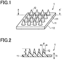
- Fig. 1 is a perspective view of an example of a needle-shaped body 1 of a first embodiment.
- the needle-shaped body 1 is used for drug administration into the skin.
- the needle-shaped body 1 is made of a thermoplastic resin.
- the needle-shaped body 1 includes a substrate 11 and a plurality of needles 12.
- the needle-shaped body 1 is, for example, a coating-type microneedle having a drug coated on the needles 12.
- the substrate 11 includes a first surface (also called a needle forming surface) 111 and a second surface (also called a non-needle forming surface) 112 located opposite to the first surface 111.
- the first surface 111 and the second surface 112 are flat surfaces parallel to each other.
- the first surface 111 and the second surface 112 are the same shape and are square. Further, the first surface 111 and the second surface 112 may be a circle or other shapes.
- a direction perpendicular to the first surface 111 and the second surface 112 is referred to as a first direction.
- a thickness (width in the first direction) of the substrate 11 is as thin as approximately 100 ⁇ m, for example. This thickness is merely an example.
- the needles 12 are formed on the first surface 111 of the substrate 11. Sixteen needles 12 are formed on the first surface 111 of the substrate 11. Any numbers of needles 12 may be provided. The needles 12 are arranged to extend in the first direction from the first surface 111 of the substrate 11.
- the needle 12 shown in Fig. 1 has a cone shape. Further, the needle 12 may be a pyramid shape or other shapes.
- the needles 12 are arranged in a regular grid pattern.
- the needles 12 may be arranged in other patterns than a regular grid pattern.
- Fig. 2 is a cross-sectional view of the needle-shaped body 1 taken along the line A-A' shown in Fig. 1 .
- exemplary dimensions of the needle-shaped body 1 according to the first embodiment will be described.
- the needle 12 has a height H in the first direction.
- the height H is in the range of 50 ⁇ m or more and 1000 ⁇ m or less. This range of the height H is required to ensure the needle 12 to pierce or puncture the skin.
- the substrate 11 has a thickness T1 in the first direction.
- the thickness T1 is in the range of 50 ⁇ m or more and 300 ⁇ m or less. If the thickness T1 of the substrate 11 is less than 50 ⁇ m, it may be difficult to cover a surface of the substrate 11 on which the needles 12 are formed. If the thickness T1 of the substrate 11 is more than 300 ⁇ m, a support member 5, which will be described later, may be unnecessary in producing the needle-shaped body 1. Therefore, the thickness T1 of the substrate 11 is in the range of 50 ⁇ m or more and 300 ⁇ m or less.
- a connection surface (virtual plane) of the first surface 111 to the needle 12 has a maximum diameter ⁇ .
- An aspect ratio (H/ ⁇ ) a ratio of the height H of the needle 12 to the maximum diameter ⁇ is in the range of 0.7 or more and 10 or less. This range of the aspect ratio (H/ ⁇ ) is required to ensure the needle 12 can pierce or puncture the skin.
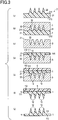
- Fig. 3 is a diagram illustrating a method for producing the needle-shaped body 1 of the first embodiment.
- the diagram of the needle-shaped body 1 shown in (g) of Fig. 3 is a cross-sectional view of the needle-shaped body 1 taken along the line A-A' shown in Fig. 1 .
- a specific example of the production method will be described below.
- a step shown in (a) of Fig. 3 is a step of preparing a prototype 2 for producing the needle-shaped body 1.
- the prototype 2 is used to produce a duplication plate 3 used for mass production of the needle-shaped bodies 1 of the same shape.
- the prototype 2 includes a substrate 21 and a plurality of needles 22.
- the substrate 21 includes a first surface 211 and a second surface 212 located opposite to the first surface 211.
- the first surface 211 and the second surface 212 are flat surfaces parallel to each other.
- the first surface 211 and the second surface 212 are the same shape.
- the shapes of the first surface 211 and the second surface 212 correspond to the shapes of the first surface 111 and the second surface 112 of the needle-shaped body 1, respectively.
- the thickness of the substrate 21 is larger than the thickness of the substrate 11 of the needle-shaped body 1.
- the needles 22 are formed on the first surface 211 of the substrate 21.
- the needles 22 are arranged to extend in a direction perpendicular to the first surface 211 of the substrate 21.
- the number, shape, arrangement, and the like of the needles 22 correspond to the number, shape, arrangement, and the like of the needles 12 of the needle-shaped body 1 to be produced.
- the prototype 2 corresponds to the shape of the needle-shaped body 1 with the thickness of the substrate 11 increased.
- the prototype 2 is made of silicon. However, other materials may be used for the prototype 2.
- a step shown in (b) of Fig. 3 is a step of producing the duplication plate 3.
- the duplication plate 3 is produced by applying the material for forming the duplication plate 3 onto the prototype 2.
- the duplication plate 3 has an inverted shape of the prototype 2 or the needle-shaped body 1 to be produced.
- the duplication plate 3 includes a first surface 31 having the same shape as that of the first surface 211 of the prototype 2 or the first surface 111 of the needle-shaped body 1 to be produced.
- the first surface 31 is a flat surface.
- the duplication plate 3 has a plurality of recesses 32 on the first surface 31.
- the recesses 32 are formed to extend in a direction perpendicular to the first surface 31.
- the shape of the recess 32 corresponds to that of the needle 22 of the prototype 2 or the needle 12 of the needle-shaped body 1 to be produced.
- the duplication plate 3 is made of a metal such as nickel (Ni) or a resin such as silicone rubber.
- other materials may be used for the duplication plate 3.
- a step shown in (c) of Fig. 3 is a step of removing the prototype 2 from the duplication plate 3.
- the prototype 2 can be removed from the duplication plate 3, for example, by using a hot alkali solution. However, other techniques may also be used.
- the duplication plate 3 which serves as a mold of the needle-shaped body 1 to be produced, can be prepared.
- the duplication plate 3 is illustrated to be inverted from (b) of Fig. 3 .
- a step shown in (d) of Fig. 3 is a step of filling a thermoplastic resin 4 into the duplication plate 3 to form the needle-shaped body 1.
- An example of this step will be described.
- the thermoplastic resin 4 is placed on the first surface 31 of the duplication plate 3.
- the thermoplastic resin 4 placed on the first surface 31 is melted.
- the thermoplastic resin 4 is pressed into the recesses 32 of the duplication plate 3 under pressure so that the thermoplastic resin 4 is filled into the recesses 32.
- the thermoplastic resin 4 is shaped by the duplication plate 3.
- the amount of the thermoplastic resin 4 to be filled into the duplication plate 3 can be adjusted so that the substrate 11 of the needle-shaped body 1 to be finally produced has a predetermined thickness.
- thermoplastic resin 4 produced by the duplication plate 3 constitutes the needle-shaped body 1.
- thermoplastic resin 4 materials for the thermoplastic resin 4 will be described.
- the needle-shaped body 1 of the present invention pierces or punctures the skin by the needles 12.
- the thermoplastic resin 4 is biocompatible.
- the needle-shaped body 1 made of a biocompatible thermoplastic resin can be safely used with the living body.
- thermoplastic resin 4 for example, polyglycolic acid (hereinafter, referred to as PGA), polylactic acid, polyethylene, polypropylene, polystyrene, polyamide, polycarbonate, cyclic polyolefin, polycaprolactone, acrylic resin, nylon resin, urethane resin, aromatic polyether ketone, polyethylene terephthalate, polyethylene naphthalate, epoxy resin or the like can be used.
- biocompatible medical grade resin such as biocompatible polyglycolic acid (hereinafter, referred to as PGA) and polylactic acid can be preferably used.
- the thermoplastic resin 4 may be other resins than those described above as long as they have thermoplasticity.
- the thermoplastic resin 4 may be a material having a low melting point. As described later, the needle-shaped body 1 may be melted during placement of the support member 5 on the second surface 112 of the needle-shaped body 1. The support member 5 is placed on the second surface 112 of the melted needle-shaped body 1 and is pressurized. As a result, the support member 5 is closely attached to the needle-shaped body 1. For this reason, the melting point of the material that constitutes the support member 5 is preferably higher than the melting point of the thermoplastic resin 4. As the melting point of the thermoplastic resin 4 becomes lower, the material for forming the support member 5 can be selected from a wide variety of materials.
- a step shown in (e) of Fig. 3 is a step of placing the support member 5 on the second surface 112 of the needle-shaped body 1. According to this step, the support member 5 is adhered to the second surface 112 of the needle-shaped body 1. The support member 5 can reinforce the substrate 11 since it is laminated on the substrate 11 of the needle-shaped body 1. The support member 5 contributes to removing the needle-shaped body 1 from the duplication plate 3.
- the support member 5 is made of a material different from the material forming the needle-shaped body 1. One of the reasons for that is that the support member 5 is finally removed from the needle-shaped body 1.
- the material for forming the support member 5 is not necessarily as expensive a material as the material forming the needle-shaped body 1, and may be an inexpensive material.
- the support member 5 may be made of a material soluble in a specific solvent.
- the material soluble in a specific solvent is a material that dissolves selectively in the specific solvent compared with the material forming the needle-shaped body 1.
- the material soluble in a specific solvent is, for example, a water-soluble material.
- the water-soluble material can use water, which is inexpensive and safe, as a solvent.
- the water-soluble material may be, for example, polyvinyl alcohol (hereinafter, referred to as PVA), cellulose and a cellulose derivative, chitosan and a chitosan derivative, polyacrylic acid polymer, polyacrylic amide (PAM), or polyethylene oxide.
- PVA polyvinyl alcohol
- PAM polyacrylic acid polymer
- PAM polyacrylic amide
- the material soluble in a specific solvent used for the support member may be other resins than those described above.
- the support member 5 may be made of a material having adhesiveness that varies in response to external stimulation.
- the external stimulation is, for example, ultraviolet light (UV), an electron beam (EB), infrared light or heat, but not limited thereto.
- An example of the material having adhesiveness that varies in response to an ultraviolet light is a material used for a dicing tape.
- An example of the material having adhesiveness that varies in response to an infrared light or heat is a heat-sensitive adhesive sheet.
- the heat-sensitive adhesive sheets may be a cool off type or a warm off type.
- a step shown in (e) of Fig. 3 is a step of placing the support member 5, some examples of which will be described below.
- thermoplastic resin 4 that constitutes the second surface 112 of the substrate 11 of the needle-shaped body 1 is melted.
- the support member 5 is placed on the second surface 112 of the needle-shaped body 1.
- pressure is applied to the support member 5.
- the support member 5 is closely attached to the needle-shaped body 1, and thus adhered to the needle-shaped body 1.
- the step of placing the support member 5 on the second surface 112 of the substrate 11 is a step of adhering the support member 5 made of a material having adhesiveness that varies in response to external stimulation to the second surface 112 of the substrate 11.
- the support member 5 is first placed on the second surface 112 of the needle-shaped body 1.
- external stimulation is applied to the support member 5.
- the adhesiveness of the support member 5 varies.
- the support member 5 is softened.
- the adhesiveness of the support member 5 is closely attached to the needle-shaped body 1, and thus adhered to the needle-shaped body 1.
- the step of placing the support member 5 on the second surface 112 of the substrate 11 shown in (e) of Fig. 3 is a step of adhering the support member 5 to the second surface 112 of the substrate 11 by using an adhesive having adhesiveness that varies in response to external stimulation.
- the support member 5 may be formed concurrently with processing the thermoplastic resin 4 into the needle-shaped body 1.
- the thermoplastic resin 4 is placed on the first surface 31 of the duplication plate 3 in the step shown in (d) of Fig. 3 .
- the support member 5 is placed on the thermoplastic resin 4, and pressure is applied to the support member 5 so that the recess 32 is filled with the thermoplastic resin 4.
- the needle-shaped body 1 is formed while the support member 5 is disposed on the second surface 112 of the needle-shaped body 1. This molding technique can reduce the number of steps for producing the needle-shaped body 1.
- a step shown in (f) of Fig. 3 is a step of removing the needle-shaped body 1 and the support member 5 which are integrally formed from the duplication plate 3. According to this step, the needle-shaped body 1 having the integrally formed support member 5 can be obtained.
- An example of demolding technique used in this step is suctioning the surface of the support member 5 opposite from the surface that is in contact with the second surface 112 of the needle-shaped body 1 by vacuuming.
- Another example of a demolding technique is pushing out the needle-shaped body 1 and the support member 5 which are integrally formed from the duplication plate 3 by using an ejector pin.
- Other demolding techniques than those described above may also be used.
- a sum of the thickness of the support member 5 and the thickness of the substrate 11 of the needle-shaped body 1 is larger than the thickness of the substrate 11 of the needle-shaped body 1 alone.
- the substrate 11 of the needle-shaped body 1 having the integrally formed support member 5 has a strength larger than that of the substrate 11 of the needle-shaped body 1 alone. Accordingly, the needle-shaped body 1 having the integrally formed support member 5 can be demolded from the duplication plate 3 with ease. Moreover, the substrate 11 of the needle-shaped body 1 does not suffer damage due to demolding.
- demolding of the needle-shaped body 1 alone will be described.
- the thickness of the substrate 11 of the needle-shaped body 1 is approximately 100 ⁇ m. Since the substrate 11 does not have sufficient strength, the needle-shaped body 1 cannot be demolded even with use of an ejector pin. If the needle-shaped body 1 was demolded, there would be a risk of damage to the needle-shaped body 1.
- a step shown in (g) of Fig. 3 is a step of removing the support member 5 from the needle-shaped body 1. Some examples of this step will be described.
- the step of removing the support member 5 from the needle-shaped body 1 shown in (g) of Fig. 3 is a step of removing the support member 5 from the needle-shaped body 1 by using a solvent in which the material constituting the support member 5 is soluble.
- the needle-shaped body 1 having the integrally formed support member 5 is immersed in a specific solvent.
- the specific solvent is a solvent in which the material constituting the support member 5 is soluble.
- the support member 5 dissolves in the specific solvent.
- Using the specific solvent promotes removal of the support member 5 from the needle-shaped body 1 without applying an external force to the support member 5.
- the needle-shaped body 1 made up of solely the thermoplastic resin 4 can be obtained.
- step (g) of Fig. 3 in which the material of the support member 5 has adhesiveness that varies in response to external stimulation will be described.
- external stimulation is applied to the support member 5.
- the external stimulation is applied to the surface of the support member 5 opposite from the surface that is in contact with the second surface 112 of the needle-shaped body 1.
- the adhesiveness of the support member 5 varies by the external stimulation.
- the adhesiveness between the support member 5 and the needle-shaped body 1 decreases.
- the support member 5 can be removed from the needle-shaped body 1.
- Applying external stimulation to the support member 5 promotes removal of the support member 5 from the needle-shaped body 1 without applying a strong external force to the support member 5.
- the needle-shaped body 1 made up of solely the thermoplastic resin 4 can be obtained.
- the step of removing the support member 5 from the needle-shaped body 1 shown in (g) of Fig. 3 is a step of removing the support member 5 from the needle-shaped body 1 by applying external stimulation.
- external stimulation is applied to the adhesive.
- the external stimulation is applied to the surface of the support member 5 opposite from the surface that is in contact with the second surface 112 of the needle-shaped body 1.
- the adhesiveness of the adhesive varies by the external stimulation. As the adhesiveness of the adhesive decreases, the adhesiveness between the support member 5 and the needle-shaped body 1 decreases.
- the support member 5 can be removed from the needle-shaped body 1.
- Applying external stimulation to the adhesive promotes removal of the support member 5 from the needle-shaped body 1 without applying a strong external force to the support member 5.
- the needle-shaped body 1 made up of solely the thermoplastic resin 4 can be obtained.
- a release agent can be used to remove the support member 5 from the needle-shaped body 1.
- Using the release agent promotes removal of the support member 5 from the needle-shaped body 1 without applying a strong external force to the support member 5.
- the needle-shaped body 1 made up of solely the thermoplastic resin 4 can be obtained.
- the needle-shaped body 1 having the thin substrate 11 can be easily produced even if the needle-shaped body 1 is formed of the thermoplastic resin 4. Further, although it is necessary to use an expensive biocompatible medical grade thermoplastic resin 4 since the needle-shaped body 1 pierces or punctures the skin, the amount of the thermoplastic resin 4 used is reduced by forming the thin substrate 11 of the needle-shaped body 1. Further, the production cost can be reduced since the needle-shaped body 1 is formed in a size that can be easily removed from the duplication plate 3.
- the needle-shaped body 1 having the thin substrate 11 has flexibility after removing the support member 5, it can be bent in conformity with the skin. Accordingly, the needle-shaped body 1 having the thin substrate 11 by removing the support member 5 can pierce and puncture the skin by the needles 12 to a sufficient extent.
- a second embodiment will be described below. Parts that may be the same as those of the first embodiment are denoted by the same reference numbers, and the description thereof will be omitted.
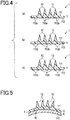
- Fig. 4 is a diagram illustrating a structure of the needle-shaped body 1 according to a second embodiment.
- Fig. 4 is a cross-sectional view of the needle-shaped body 1 taken along the line A-A' shown in Fig. 1 .
- the diagram shown in (a) of Fig. 4 is an example of the needle-shaped body 1 according to the second embodiment.
- a plurality of recesses (also called dimple structures) 112a are formed on the second surface 112 of the needle-shaped body 1.
- the recess 112a has a hemisphere shape. Further, the recess 112a may be a rectangular shape or other shapes.
- the recesses 112a may be arranged in a regular grid pattern or other patterns than a regular grid pattern.
- the recesses 112a are transferred by the support member 5 in the step shown in (e) of Fig. 3 . Projections that correspond to the recesses 112a are formed on the surface of the support member 5 that is in contact with the second surface 112 of the needle-shaped body 1.
- the recesses 112a are formed by transferring the shapes corresponding to the projections formed on the surface of the support member 5 that is in contact with the second surface 112 of the needle-shaped body 1.
- the diagram shown in (b) of Fig. 4 is an example of the needle-shaped body 1 according to the second embodiment.
- a plurality of projections (also called embossed structures) 112b are formed on the second surface 112 of the needle-shaped body 1.
- the projection 112b has a hemisphere shape. Further, the projection 112b may be other shapes.
- the projections 112b may be arranged in a regular grid pattern or other patterns than a regular grid pattern.
- the projections 112b are transferred by the support member 5 in the step shown in (e) of Fig. 3 .
- Recesses that correspond to the projections 112b are formed on the surface of the support member 5 that is in contact with the second surface 112 of the needle-shaped body 1.
- the projections 112b are formed by transferring the shapes corresponding to the recesses formed on the surface of the support member 5 that is in contact with the second surface 112 of the needle-shaped body 1.
- the diagram shown in (c) of Fig. 4 is an example of the needle-shaped body 1 according to the second embodiment.
- a plurality of projections (also called embossed structures) 112c are formed on the second surface 112 of the needle-shaped body 1.
- the projection 112c has a rectangular shape. Further, the projection 112c may be other shapes.
- the projections 112c may be arranged in a regular grid pattern or other patterns than a regular grid pattern.
- the projections 112c are transferred by the support member 5 in the step shown in (e) of Fig. 3 .
- Recesses that correspond to the projections 112c are formed on the surface of the support member 5 that is in contact with the second surface 112 of the needle-shaped body 1.
- the projections 112c are formed by transferring the shapes corresponding to the recesses formed on the surface of the support member 5 that is in contact with the second surface 112 of the needle-shaped body 1.
- recesses or projections such as a pear-skin finish, or combination thereof may be provided on the second surface 112 of the needle-shaped body 1.
- the needle-shaped body 1 and the support member 5 engage with each other in the step shown in (e) of Fig. 3 .
- the recesses 112a formed on the second surface 112 of the needle-shaped body 1 engage the projections formed on the support member 5 for producing the recesses 112a.
- the projections 112b or the projections 112c formed on the second surface 112 of the needle-shaped body 1 engage the recesses formed on the support member 5 for producing the projections 112b or the projections 112c.
- the support member 5 and the needle-shaped body 1 can be more reliably adhered to each other in the step of placing the support member 5 on the second surface 112 of the needle-shaped body 1.
- the needle-shaped body 1 having the integrally formed support member 5 can be easily handled.
- a structure corresponding to the surface structure of the support member 5 may be provided on the second surface 112 of the needle-shaped body 1.
- a lot number or a product number may be formed on the surface of the support member 5 that is in contact with the second surface 112 of the needle-shaped body 1.
- a structure that corresponds to the surface structure of the support member 5 is transferred to the second surface 112 of the needle-shaped body 1.
- a third embodiment will be described below. Parts that may be the same as those of the first embodiment or the second embodiment are denoted by the same reference numbers, and the description thereof will be omitted.
- Fig. 5 is a diagram illustrating a structure of the needle-shaped body 1 according to the third embodiment.
- a reinforcement layer 6 has a convex curved surface 61 which is curved at a predetermined curvature.
- the reinforcement layer 6 is made of a metal, for example, but may be made of other materials.
- the second surface 112 of the needle-shaped body 1 is adhered to the convex curved surface 61 of the reinforcement layer 6.
- the second surface 112 of the needle-shaped body 1 is adhered to the curved surface 61, for example, by using an adhesive.
- the needle-shaped body 1 has the substrate 11 curved into a convex shape along the shape of the reinforcement layer 6.
- the substrate 11 can be curved since the needle-shaped body 1 has the thin substrate 11 as described in the first embodiment.
- the substrate 11 can be curved without causing damage.
- the needle-shaped body 1 has the substrate 11 with the thickness of approximately 1000 ⁇ m.
- the substrate 11 with such a thickness cannot be flexibly curved. If this substrate 11 is curved, the substrate 11 is damaged.
- the method of producing the needle-shaped body 1 described in the first embodiment may also include a step of adhering the second surface 112 of the substrate 11, with the support member 5 removed, to the convex curved surface 61 of the reinforcement layer 6.
- the needle-shaped body 1 in the shape that can be readily pierced into the skin compared with the needle-shaped body 1 having a plate-shaped substrate 11 can be provided.
- a fourth embodiment will be described below. Parts that may be the same as those of the first embodiment, the second embodiment or the third embodiment are denoted by the same reference numbers, and the description thereof will be omitted.
- Fig. 6 is a diagram illustrating a method for producing the needle-shaped body of the fourth embodiment.
- the diagram shown in (g) of Fig. 6 is a cross-sectional view of the needle-shaped body 1 taken along the line A-A' shown in Fig. 1 .
- Fig. 6 illustrates a method for producing the needle-shaped body 1 having the recesses 112a which is shown in (a) of Fig. 4 in conjunction with the second embodiment.
- the method for producing the needle-shaped body 1 having the projections 112b which is shown in (b) of Fig. 4 may be the same as the production method described below, and the description thereof will be omitted.
- the method for producing the needle-shaped body 1 having the projections 112c which is shown in (c) of Fig. 4 may be the same as the production method described below, and the description thereof will be omitted.
- Steps shown in (a) to (d) of Fig. 6 may be the same as the steps described above with reference to (a) to (d) of Fig. 3 , and the description thereof will be omitted.
- the step shown in (e) of Fig. 6 is the same as the step described above with reference to (e) of Fig. 3 , except that the support member 5 has a shape different from that of the first embodiment.
- points different from the first embodiment will be described.
- a plurality of projections (also called embossed structures) 511 are formed on a surface 51 of the support member 5 that is in contact with the second surface 112 of the needle-shaped body 1.
- the shapes which correspond to the projections 511 are transferred to the second surface 112 of the needle-shaped body 1.
- the recesses 112a having the shapes which correspond to the projections 511 are formed on the second surface 112 of the needle-shaped body 1.
- the recesses 112a formed on the second surface 112 of the needle-shaped body 1 engage the projections 511 formed on the support member 5. As a result, the support member 5 and the needle-shaped body 1 are more reliably adhered to each other.
- a step shown in (f) of Fig. 6 may be the same as the step described above with reference to (f) of Fig. 3 , and the description thereof will be omitted. Further, since the support member 5 and the needle-shaped body 1 are reliably adhered to each other as described above, the needle-shaped body 1 having the integrally formed support member 5 can be easily demolded.
- a step shown in (g) of Fig. 6 is the same as the step described above with reference to (g) of Fig. 3 , and the description thereof will be omitted. According to this step, the needle-shaped body 1 having the recesses 112a made up of solely the thermoplastic resin 4 can be obtained.
- a step shown in (h) of Fig. 6 is a step of adhering the second surface 112 of the substrate 11, with the support member 5 removed, to the convex curved surface 61 of the reinforcement layer 6.
- the second surface 112 of the needle-shaped body 1 is adhered to the curved surface 61 by using an adhesive. According to this step, the needle-shaped body 1 having the substrate 11 curved into a convex shape along the shape of the reinforcement layer 6 can be obtained.
- the method of producing the needle-shaped body 1 according to the fourth embodiment may not necessarily include the step shown in (h) of Fig. 6 .
- a fifth embodiment will be described below. Parts that may be the same as those of the first to fourth embodiments are denoted by the same reference numbers, and the description thereof will be omitted.
- Fig. 7 is a cross-sectional view of a needle-shaped body 101 according to the fifth embodiment.
- the needle-shaped body 101 includes a needle-shaped body main body 10 and the support member 5.
- the needle-shaped body main body 10 includes the substrate 11 and a plurality of needles 12.
- the needle-shaped body main body 10 corresponds to the needle-shaped body 1 described in the first embodiment.
- the support member 5 is disposed on the second surface 112 of the substrate 11. Further, the material for forming the support member 5 is not limited to the materials described in the first embodiment.
- the support member 5 may be made of a general resin film (sheet).
- Examples of the resin film for forming the support member 5 include polyglycolic acid (hereinafter, referred to as PGA), polylactic acid, polyethylene, polypropylene, polystyrene, polyamide, polycarbonate, cyclic polyolefin, polycaprolactone, acrylic resin, urethane resin, aromatic polyether ketone, nylon resin, polyethylene terephthalate, polyethylene naphthalate, and resin films made of a thermoplastic resin such as epoxy resin.
- a non-biocompatible thermoplastic resin may be used as the resin film for forming the support member.
- the resin film used for the support member may be other resins than those described above.
- thermoplastic resin 4 used for the needle-shaped body 1 and the thermoplastic resin used for the support member 5 may be the same material.
- the thermoplastic resin 4 used for the needle-shaped body 1 may be an expensive biocompatible resin, and the thermoplastic resin used for the support member 5 may be inexpensive general grade resin.
- the support member 5 has a thickness T2 in the first direction.
- a sum of the thickness T1 of the substrate 11 and the thickness T2 of the support member 5 is in the range of 400 ⁇ m or more and 1500 ⁇ m or less.
- the sum of T1 and T2 is less than 400 ⁇ m, easy removal of the needle-shaped body 1 from the duplication plate in production of the needle-shaped body 1 may be difficult.
- the sum of T1 and T2 is more than 1500 ⁇ m, the production cost increases. Therefore, the sum of T1 and T2 is preferably in the range of 400 ⁇ m or more and 1500 ⁇ m or less.
- Fig. 8 is a cross-sectional view of a modified example of the needle-shaped body 101 according to the fifth embodiment.
- the needle-shaped body 101 shown in Fig. 8 includes an adhesive layer 7 between the needle-shaped body main body 10 and the support member 5.
- the material for the adhesive layer 7 is not limited as long as the adhesive layer 7 can adhere the needle-shaped body main body 10 to the support member 5.
- Fig. 9 is a diagram illustrating an example of the method for producing the needle-shaped body 101.
- the method shown in Fig. 9 uses injection molding (film insert molding).
- a step shown in (a) of Fig. 9 is a step of placing the support member 5 in a first duplication plate 300.
- the first duplication plate 300 has an inverted shape of the support member 5 of the needle-shaped body 101 to be produced.
- the first duplication plate 300 is also called an intaglio plate or a mold.
- a step shown in (b) of Fig. 9 is a step of mating the first duplication plate 300 and the second duplication plate 301.
- the second duplication plate 301 has an inverted shape of the needle-shaped body main body 10 of the needle-shaped body 101 to be produced.
- the second duplication plate 301 has recess that correspond to the shapes of the needles 12 of the needle-shaped body 101 to be produced.
- the second duplication plate 301 is also called an intaglio plate or a mold.
- a step shown in (c) of Fig. 9 is a step of forming the needle-shaped body 101 by ejecting the thermoplastic resin 4 into a space formed by the first duplication plate 300 and the second duplication plate 301.
- the thermoplastic resin 4 is integrally formed with the support member 5 on the support member 5.
- the thermoplastic resin 4 becomes the needle-shaped body main body 10 by the first duplication plate 300 and the second duplication plate 301.
- a step shown in (d) of Fig. 9 is a step of removing the needle-shaped body main body 10 and the support member 5 which are integrally formed from the first duplication plate 300 and the second duplication plate 301. According to this step, the needle-shaped body 101 is removed from the first duplication plate 300 and the second duplication plate 301.
- the needle-shaped body 101 can be produced by the steps (a) to (f) of Fig. 3 described in the method for producing the needle-shaped body 1 of the first embodiment.
- the method for producing the needle-shaped body 101 includes a step of preparing the prototype 2 for producing the needle-shaped body 1.
- the method for producing the needle-shaped body 101 includes a step of producing the duplication plate 3.
- the method for producing the needle-shaped body 101 includes a step of removing the prototype 2 from the duplication plate 3.
- the method for producing the needle-shaped body 101 includes a step of filling the thermoplastic resin 4 into the duplication plate 3 to form the needle-shaped body main body 10 which corresponds to the needle-shaped body 1.
- the method for producing the needle-shaped body 101 includes a step of placing the support member 5 on the second surface 112 of the needle-shaped body main body 10.
- the method for producing the needle-shaped body 101 includes a step of removing the needle-shaped body main body 10 and the support member 5 which are integrally formed from the duplication plate 3.
- the needle-shaped body 1 and the method for producing the needle-shaped body 1 can achieve the same effects as those described in the first to fourth embodiments.
- the method for producing the needle-shaped body will be described by using specific examples. As a matter of course, the method for producing the needle-shaped body is not limited to examples described below, and other production methods that would occur to a person having ordinary skill in the art are contemplated.
- the shape of the needle-shaped body 1 produced in Example 1 will be described.
- the needle-shaped body 1 was made of PGA.
- the needle 12 had a height of 800 ⁇ m.
- a bottom length of the needle 12 was 300 ⁇ m.
- Sixteen needles 12 were arranged in 4 x 4 regular grid pattern.
- a pitch between the needles 12 was 800 ⁇ m.
- the outer shape of the substrate 11 was a 5 mm square.
- the substrate 11 had a thickness of 100 ⁇ m.
- the prototype 2 produced by using a five-axis processing center was prepared. Silicon was used as a material for the prototype 2.
- the duplication plate 3 serving as a mold of the needle-shaped body 1 to be produced was prepared.
- the duplication plate 3 was a Ni plate formed by electrocasting, which was left after the silicon was removed.
- one of medical grade biocompatible resins PGA was filled into the duplication plate 3 to thereby form the needle-shaped body 1.
- PGA was placed on the duplication plate 3.
- the amount of PGA filled into the duplication plate 3 was adjusted so that the substrate 11 had the intended thickness.
- PGA placed on the duplication plate 3 was heated at 250°C and melted.
- a sheet made of PVA was placed on the melted PGA.
- the sheet made of PVA had the thickness of 400 ⁇ m.
- This PVA sheet constituted the support member 5. Then, pressure was applied to a rear surface of the PVA sheet (the surface that is not in contact with PGA) by using a roller made of a silicone rubber.
- the duplication plate 3 was cooled from both surfaces. After the temperature of the duplication plate 3 was decreased to around room temperature, vacuum tweezers were applied to the rear surface of the PVA sheet for peeling off in a direction perpendicular to the duplication plate 3. As a result, the needle-shaped body 1 having the substrate 11 and the needles 12 made of PGA and the PVA sheet adhered to the second surface 112 of the substrate 11 were obtained as a unit.
- Example 2 a specific method for producing the needle-shaped body 1 according to the second embodiment will be described.
- the embossed structures 511 were formed on one surface of the support member 5.
- the duplication plate 3 serving as a mold of the needle-shaped body 1 to be produced as with Example 1 was produced.
- one of medical grade biocompatible resins PGA was filled into the duplication plate 3 to thereby form the needle-shaped body 1.
- PGA was placed on the duplication plate 3.
- the amount of PGA filled into the duplication plate 3 was adjusted so that the substrate 11 had the intended thickness.
- PGA placed on the duplication plate 3 was heated at 250°C and melted.
- pressure was applied to PGA from the above by using a roller made of a silicone rubber to thereby push the PGA into the recesses 32 of the duplication plate 3.
- a sheet made of PVA was placed on the melted PGA.
- the embossed structures 511 with the radius of 5 ⁇ m were formed on one surface (the surface that is in contact with PGA) of the PVA sheet.
- the PVA sheet had the thickness of 400 ⁇ m. Then, pressure was applied to a rear surface of the PVA sheet (the surface that is not in contact with PGA) by using a roller made of a silicone rubber.
- the duplication plate 3 was cooled from both surfaces. After the temperature of the duplication plate 3 was decreased to around room temperature, vacuum tweezers were applied to the rear surface of the PVA sheet for peeling off in a direction perpendicular to the duplication plate 3. As a result, the needle-shaped body 1 having the substrate 11 and the needles 12 made of PGA and the PVA sheet adhered to the second surface 112 of the substrate 11 were obtained as a unit. On the second surface 112 of the substrate 11, the dimple structures 112a which correspond to the shapes of the embossed structures 511 of the PVA sheet were formed.
- the needle-shaped body 1 made of PGA was adhered to the reinforcement layer 6 made of a stainless steel (for example, SUS304) with the curvature of 50 mm.
- the shape of the needle-shaped body 101 produced in Example 5 which is shown in Fig. 7 will be described.
- the needle 12 of the needle-shaped body 101 had the same shape as the needle 12 of Example 1.
- the height of the needle 12 was 800 ⁇ m and the bottom length was 300 ⁇ m.
- Sixteen needles 12 were arranged in 4 x 4 regular grid pattern.
- a pitch between the needles 12 was 800 ⁇ m.
- the outer shape of the substrate 11 was a 5-mm square.
- the substrate 11 had a thickness of 100 ⁇ m.
- the prototype 2 produced by using a five-axis processing center was prepared. Silicon was used as a material for the prototype 2.
- the duplication plate 3 serving as a mold of the needle-shaped body 1 to be produced was prepared.
- the duplication plate 3 was a Ni plate formed by electrocasting, which was left after the silicon was removed.
- one of medical grade biocompatible resins was filled into the duplication plate 3 to thereby form the needle-shaped body.
- PGA was placed on the duplication plate 3.
- the amount of PGA filled into the duplication plate 3 was adjusted so that the substrate 11 had the intended thickness.
- PGA placed on the duplication plate 3 was heated at 250°C and melted.
- pressure was applied to the PGA from the above by using a roller made of a silicone rubber to thereby push the PGA into the recesses 32 of the duplication plate 3.
- a sheet made of general grade PGA which is non-biocompatible was placed on the melted PGA.
- the PVA sheet had the thickness of 400 ⁇ m, and was less expensive than the medical grade raw PGA which was used for the needle-shaped body.
- This PGA sheet constitutes the support member 5. Then, pressure was applied to a rear surface of the PGA sheet by using a roller made of a silicone rubber.
- the duplication plate 3 was cooled from both surfaces. After the temperature of the duplication plate 3 was decreased to around room temperature, vacuum tweezers were applied to the rear surface of the PVA sheet for peeling off in a direction perpendicular to the duplication plate 3. As a result, the needle-shaped body 1 having the substrate 11 and the needles 12 made of PGA and the PGA sheet adhered to the second surface 112 of the substrate 11 were obtained as a unit. Thus, the needle-shaped body 101 shown in Fig. 7 was obtained.
- support member 61...Curved surface, 101...Needle-shaped body, 111...First surface (needle forming surface) of needle-shaped body, 112...Second surface (non-needle forming surface) of needle-shaped body, 112a...Recess (dimple structure), 112b...Projection (embossed structure), 112c...Projection (embossed structure), 211...First surface of prototype, 212... Second surface of prototype, 511...Projection (embossed structure) of support member, 300...First duplication plate, 301...Second duplication plate
Landscapes
- Engineering & Computer Science (AREA)
- Health & Medical Sciences (AREA)
- Mechanical Engineering (AREA)
- Manufacturing & Machinery (AREA)
- Microelectronics & Electronic Packaging (AREA)
- Chemical Kinetics & Catalysis (AREA)
- General Chemical & Material Sciences (AREA)
- Chemical & Material Sciences (AREA)
- Medical Informatics (AREA)
- Dermatology (AREA)
- Anesthesiology (AREA)
- Biomedical Technology (AREA)
- Heart & Thoracic Surgery (AREA)
- Hematology (AREA)
- Life Sciences & Earth Sciences (AREA)
- Animal Behavior & Ethology (AREA)
- General Health & Medical Sciences (AREA)
- Public Health (AREA)
- Veterinary Medicine (AREA)
- Computer Hardware Design (AREA)
- Media Introduction/Drainage Providing Device (AREA)
Abstract
Description
- The present invention relates to needle-shaped bodies used for drug administration into the skin and a method for producing the needle-shaped bodies.
- Drug administration by injection has been widely used for injection of a drug such as vaccine into the body. Although injection is a highly safe method for administration, it often causes severe pain since an injection needle is deeply pierced into the body to deliver the drug into the subcutaneous tissue. Further, particularly in developing countries, there are many issues such as infection by reuse of injection needle and needle stick accidents.
- Therefore, as an alternative drug administration method to injection, attention has been paid to use of an array of a plurality of needle members of micron order to pierce the skin for direct administration of a drug into the skin. According to this method, it is possible to almost avoid producing pain during piercing into the skin since the length of the needle members is controlled not to reach the nerve cells in the dermis layer. Moreover, a drug can be intradermally administered in a convenient manner without using a special tool for drug administration (see
PTLs 1 and 2). - Further, when vaccine is intradermally administered using the needle members, the amount of vaccine used can be reduced compared with subcutaneous injection since antigen presenting cells are abundant in the skin.
- The needle member must have a thinness and sharpness sufficient for puncturing the skin and a length sufficient for intradermal drug delivery. Accordingly, the needle member desirably has a diameter of several micrometers to several hundreds of micrometers and a length that penetrates through the stratum corneum which is the outermost layer of the skin but does not reach the nerve fibers, which is specifically several tens of micrometers to several hundreds of micrometers.
- Materials for the needle member are required to be harmless to the human body even if the needle member is broken and left in the body. For such materials, biocompatible resins such as medical grade silicone, maltose, polyglycolic acid, polylactic acid, and dextran are regarded as promising materials (see PTL 3).
-
- [PTL 1]
-
JP 2006-345983 A - [PTL 2]
-
JP 2006-341089 A - [PTL 3]
-
JP 2005-21677 A - For mass production of a fine structure such as the needle member by using the above resin materials with low cost, a transfer molding process such as injection molding, imprinting or casting is effective. However, in any of the above processes, a mold having an inverted shape of a desired shape is necessary. Accordingly, there is a problem that production of a structure having a high aspect ratio (ratio of the height or depth to a diameter of the structure) requires complicated production steps.
- These biocompatible resins are expensive in cost compared with general resin materials, and one of the effective techniques for cost reduction is reducing the amount of use without impairing the function.
- Further, by reducing the thickness of a substrate, which is a portion other than the needle, the substrate can flexibly deform in conformity with the irregularities of a target object.
- However, for example in producing a needle-shaped body having a thin substrate with approximately 100 µm thickness, a production method may become a matter of consideration.
- In particular, when the needle-shaped body is produced by plastic molding, demolding by using a general ejector pin cannot be performed since the substrate does not have a sufficient strength.
- Moreover, there is a difficulty in handling after molding.
- The present invention has been made in view of the above problem. An object of the invention is to provide a needle-shaped body having a thin substrate and a method for producing the needle-shaped body in a convenient and inexpensive manner.
- A needle-shaped body according to an aspect of the present invention includes a plurality of needles; and a substrate having a first surface on which the needles are formed and a second surface opposite to the first surface, wherein a height H of each of the needles in a direction perpendicular to the first surface is 50 µm or more and 1000 µm or less, a thickness T1 of the substrate in a direction perpendicular to the first surface is 50 µm or more and 300 µm or less, and an aspect ratio (H/ϕ), which is a ratio of the height H of the each of the needles to a maximum diameter ϕ of a connection surface of the first surface to the needles is in a range of 0.7 or more and 10 or less.
- A method for producing a needle-shaped body having needles on a first surface of a substrate made of a thermoplastic resin according to an aspect of the present invention, the method includes the steps of: forming the needle-shaped body by filling the thermoplastic resin into a duplication plate having recesses that correspond to shapes of the needles; providing a support member made of a material different from a material for the needle-shaped body on a second surface of the substrate which is opposite to the first surface; and removing the needle-shaped body and the support member which are integrally formed from the duplication plate.
- According to the present invention, a needle-shaped body having a thin substrate can be produced even if the needle-shaped body is made of a thermoplastic resin.
-
-
Fig. 1 is a perspective view of a needle-shaped body according to a first embodiment of the present invention. -
Fig. 2 is a cross-sectional view of the needle-shaped body according to the first embodiment of the present invention. -
Fig. 3 is a diagram illustrating a method for producing the needle-shaped body according to the first embodiment of the present invention. -
Fig. 4 is a diagram illustrating a structure of the needle-shaped body according to a second embodiment of the present invention. -
Fig. 5 is a diagram illustrating a structure of the needle-shaped body according to a third embodiment of the present invention. -
Fig. 6 is a diagram illustrating a method for producing the needle-shaped body according to a fourth embodiment of the present invention. -
Fig. 7 is a cross-sectional view of the needle-shaped body according to a fifth embodiment of the present invention. -
Fig. 8 is a cross-sectional view of a modified example of the needle-shaped body according to a fifth embodiment of the present invention. -
Fig. 9 is a diagram illustrating a method for producing the needle-shaped body according to the fifth embodiment of the present invention. - With reference to the drawings, a structure of a needle-shaped body and a method for producing the needle-shaped body according to embodiments of the present invention will be described in detail. Drawings are schematic diagrams of the embodiments for promoting understanding of the embodiments. Although the shapes, dimensions and ratios may be different from those of the actual components, the design can be appropriately changed.
-
Fig. 1 is a perspective view of an example of a needle-shaped body 1 of a first embodiment. The needle-shaped body 1 is used for drug administration into the skin. The needle-shaped body 1 is made of a thermoplastic resin. - The needle-
shaped body 1 includes asubstrate 11 and a plurality ofneedles 12. The needle-shaped body 1 is, for example, a coating-type microneedle having a drug coated on theneedles 12. Thesubstrate 11 includes a first surface (also called a needle forming surface) 111 and a second surface (also called a non-needle forming surface) 112 located opposite to thefirst surface 111. Thefirst surface 111 and thesecond surface 112 are flat surfaces parallel to each other. Thefirst surface 111 and thesecond surface 112 are the same shape and are square. Further, thefirst surface 111 and thesecond surface 112 may be a circle or other shapes. In the first embodiment, a direction perpendicular to thefirst surface 111 and thesecond surface 112 is referred to as a first direction. A thickness (width in the first direction) of thesubstrate 11 is as thin as approximately 100 µm, for example. This thickness is merely an example. - The
needles 12 are formed on thefirst surface 111 of thesubstrate 11. Sixteen needles 12 are formed on thefirst surface 111 of thesubstrate 11. Any numbers ofneedles 12 may be provided. Theneedles 12 are arranged to extend in the first direction from thefirst surface 111 of thesubstrate 11. Theneedle 12 shown inFig. 1 has a cone shape. Further, theneedle 12 may be a pyramid shape or other shapes. Theneedles 12 are arranged in a regular grid pattern. Theneedles 12 may be arranged in other patterns than a regular grid pattern. -
Fig. 2 is a cross-sectional view of the needle-shapedbody 1 taken along the line A-A' shown inFig. 1 . With reference toFig. 2 , exemplary dimensions of the needle-shapedbody 1 according to the first embodiment will be described. - The
needle 12 has a height H in the first direction. The height H is in the range of 50 µm or more and 1000 µm or less. This range of the height H is required to ensure theneedle 12 to pierce or puncture the skin. - The
substrate 11 has a thickness T1 in the first direction. The thickness T1 is in the range of 50 µm or more and 300 µm or less. If the thickness T1 of thesubstrate 11 is less than 50 µm, it may be difficult to cover a surface of thesubstrate 11 on which theneedles 12 are formed. If the thickness T1 of thesubstrate 11 is more than 300 µm, asupport member 5, which will be described later, may be unnecessary in producing the needle-shapedbody 1. Therefore, the thickness T1 of thesubstrate 11 is in the range of 50 µm or more and 300 µm or less. - A connection surface (virtual plane) of the
first surface 111 to theneedle 12 has a maximum diameter ϕ. An aspect ratio (H/ϕ), a ratio of the height H of theneedle 12 to the maximum diameter ϕ is in the range of 0.7 or more and 10 or less. This range of the aspect ratio (H/ϕ) is required to ensure theneedle 12 can pierce or puncture the skin. -
Fig. 3 is a diagram illustrating a method for producing the needle-shapedbody 1 of the first embodiment. The diagram of the needle-shapedbody 1 shown in (g) ofFig. 3 is a cross-sectional view of the needle-shapedbody 1 taken along the line A-A' shown inFig. 1 . A specific example of the production method will be described below. - A step shown in (a) of
Fig. 3 is a step of preparing aprototype 2 for producing the needle-shapedbody 1. - The
prototype 2 is used to produce aduplication plate 3 used for mass production of the needle-shapedbodies 1 of the same shape. Theprototype 2 includes asubstrate 21 and a plurality ofneedles 22. - The
substrate 21 includes afirst surface 211 and asecond surface 212 located opposite to thefirst surface 211. Thefirst surface 211 and thesecond surface 212 are flat surfaces parallel to each other. Thefirst surface 211 and thesecond surface 212 are the same shape. The shapes of thefirst surface 211 and thesecond surface 212 correspond to the shapes of thefirst surface 111 and thesecond surface 112 of the needle-shapedbody 1, respectively. The thickness of thesubstrate 21 is larger than the thickness of thesubstrate 11 of the needle-shapedbody 1. - The
needles 22 are formed on thefirst surface 211 of thesubstrate 21. Theneedles 22 are arranged to extend in a direction perpendicular to thefirst surface 211 of thesubstrate 21. The number, shape, arrangement, and the like of theneedles 22 correspond to the number, shape, arrangement, and the like of theneedles 12 of the needle-shapedbody 1 to be produced. As described above, theprototype 2 corresponds to the shape of the needle-shapedbody 1 with the thickness of thesubstrate 11 increased. For example, theprototype 2 is made of silicon. However, other materials may be used for theprototype 2. - A step shown in (b) of
Fig. 3 is a step of producing theduplication plate 3. Theduplication plate 3 is produced by applying the material for forming theduplication plate 3 onto theprototype 2. Theduplication plate 3 has an inverted shape of theprototype 2 or the needle-shapedbody 1 to be produced. - That is, the
duplication plate 3 includes afirst surface 31 having the same shape as that of thefirst surface 211 of theprototype 2 or thefirst surface 111 of the needle-shapedbody 1 to be produced. Thefirst surface 31 is a flat surface. Theduplication plate 3 has a plurality ofrecesses 32 on thefirst surface 31. Therecesses 32 are formed to extend in a direction perpendicular to thefirst surface 31. The shape of therecess 32 corresponds to that of theneedle 22 of theprototype 2 or theneedle 12 of the needle-shapedbody 1 to be produced. For example, theduplication plate 3 is made of a metal such as nickel (Ni) or a resin such as silicone rubber. However, other materials may be used for theduplication plate 3. - A step shown in (c) of
Fig. 3 is a step of removing theprototype 2 from theduplication plate 3. Theprototype 2 can be removed from theduplication plate 3, for example, by using a hot alkali solution. However, other techniques may also be used. According to the step of removing theprototype 2, theduplication plate 3, which serves as a mold of the needle-shapedbody 1 to be produced, can be prepared. In (c) ofFig. 3 , theduplication plate 3 is illustrated to be inverted from (b) ofFig. 3 . - A step shown in (d) of
Fig. 3 is a step of filling athermoplastic resin 4 into theduplication plate 3 to form the needle-shapedbody 1. An example of this step will be described. First, thethermoplastic resin 4 is placed on thefirst surface 31 of theduplication plate 3. Then, thethermoplastic resin 4 placed on thefirst surface 31 is melted. Then, thethermoplastic resin 4 is pressed into therecesses 32 of theduplication plate 3 under pressure so that thethermoplastic resin 4 is filled into therecesses 32. Thethermoplastic resin 4 is shaped by theduplication plate 3. The amount of thethermoplastic resin 4 to be filled into theduplication plate 3 can be adjusted so that thesubstrate 11 of the needle-shapedbody 1 to be finally produced has a predetermined thickness. The supply amount of thethermoplastic resin 4 to theduplication plate 3 can be limited, or the excess of thethermoplastic resin 4 can be reused by placing outside the frame of theduplication plate 3. Accordingly, a substantial increase in the production cost of thesubstrate 11 can be prevented while maintaining a predetermined thickness of thesubstrate 11. Thethermoplastic resin 4 produced by theduplication plate 3 constitutes the needle-shapedbody 1. - Next, materials for the
thermoplastic resin 4 will be described. - The needle-shaped
body 1 of the present invention pierces or punctures the skin by theneedles 12. For this reason, thethermoplastic resin 4 is biocompatible. The needle-shapedbody 1 made of a biocompatible thermoplastic resin can be safely used with the living body. - For the
thermoplastic resin 4, for example, polyglycolic acid (hereinafter, referred to as PGA), polylactic acid, polyethylene, polypropylene, polystyrene, polyamide, polycarbonate, cyclic polyolefin, polycaprolactone, acrylic resin, nylon resin, urethane resin, aromatic polyether ketone, polyethylene terephthalate, polyethylene naphthalate, epoxy resin or the like can be used. Among others, biocompatible medical grade resin such as biocompatible polyglycolic acid (hereinafter, referred to as PGA) and polylactic acid can be preferably used. Further, thethermoplastic resin 4 may be other resins than those described above as long as they have thermoplasticity. - The
thermoplastic resin 4 may be a material having a low melting point. As described later, the needle-shapedbody 1 may be melted during placement of thesupport member 5 on thesecond surface 112 of the needle-shapedbody 1. Thesupport member 5 is placed on thesecond surface 112 of the melted needle-shapedbody 1 and is pressurized. As a result, thesupport member 5 is closely attached to the needle-shapedbody 1. For this reason, the melting point of the material that constitutes thesupport member 5 is preferably higher than the melting point of thethermoplastic resin 4. As the melting point of thethermoplastic resin 4 becomes lower, the material for forming thesupport member 5 can be selected from a wide variety of materials. - A step shown in (e) of
Fig. 3 is a step of placing thesupport member 5 on thesecond surface 112 of the needle-shapedbody 1. According to this step, thesupport member 5 is adhered to thesecond surface 112 of the needle-shapedbody 1. Thesupport member 5 can reinforce thesubstrate 11 since it is laminated on thesubstrate 11 of the needle-shapedbody 1. Thesupport member 5 contributes to removing the needle-shapedbody 1 from theduplication plate 3. - Materials for forming the
support member 5 will be described. Thesupport member 5 is made of a material different from the material forming the needle-shapedbody 1. One of the reasons for that is that thesupport member 5 is finally removed from the needle-shapedbody 1. The material for forming thesupport member 5 is not necessarily as expensive a material as the material forming the needle-shapedbody 1, and may be an inexpensive material. - The
support member 5 may be made of a material soluble in a specific solvent. The material soluble in a specific solvent is a material that dissolves selectively in the specific solvent compared with the material forming the needle-shapedbody 1. The material soluble in a specific solvent is, for example, a water-soluble material. The water-soluble material can use water, which is inexpensive and safe, as a solvent. The water-soluble material may be, for example, polyvinyl alcohol (hereinafter, referred to as PVA), cellulose and a cellulose derivative, chitosan and a chitosan derivative, polyacrylic acid polymer, polyacrylic amide (PAM), or polyethylene oxide. The material soluble in a specific solvent used for the support member may be other resins than those described above. - The
support member 5 may be made of a material having adhesiveness that varies in response to external stimulation. The external stimulation is, for example, ultraviolet light (UV), an electron beam (EB), infrared light or heat, but not limited thereto. An example of the material having adhesiveness that varies in response to an ultraviolet light is a material used for a dicing tape. An example of the material having adhesiveness that varies in response to an infrared light or heat is a heat-sensitive adhesive sheet. The heat-sensitive adhesive sheets may be a cool off type or a warm off type. - A step shown in (e) of
Fig. 3 is a step of placing thesupport member 5, some examples of which will be described below. - First, the
thermoplastic resin 4 that constitutes thesecond surface 112 of thesubstrate 11 of the needle-shapedbody 1 is melted. Then, thesupport member 5 is placed on thesecond surface 112 of the needle-shapedbody 1. Then, pressure is applied to thesupport member 5. Thesupport member 5 is closely attached to the needle-shapedbody 1, and thus adhered to the needle-shapedbody 1. - An example of the step shown in (e) of
Fig. 3 , in which the material has adhesiveness that varies in response to external stimulation will be described. As shown in (e) ofFig. 3 , the step of placing thesupport member 5 on thesecond surface 112 of thesubstrate 11 is a step of adhering thesupport member 5 made of a material having adhesiveness that varies in response to external stimulation to thesecond surface 112 of thesubstrate 11. In this step, thesupport member 5 is first placed on thesecond surface 112 of the needle-shapedbody 1. Then, external stimulation is applied to thesupport member 5. Accordingly, the adhesiveness of thesupport member 5 varies. For example, thesupport member 5 is softened. By virtue of the adhesiveness of thesupport member 5, thesupport member 5 is closely attached to the needle-shapedbody 1, and thus adhered to the needle-shapedbody 1. - Further, rather than the material of the
support member 5 having such adhesiveness, an adhesive having adhesiveness that varies in response to external stimulation may be used. In this case, the step of placing thesupport member 5 on thesecond surface 112 of thesubstrate 11 shown in (e) ofFig. 3 is a step of adhering thesupport member 5 to thesecond surface 112 of thesubstrate 11 by using an adhesive having adhesiveness that varies in response to external stimulation. - In addition, the
support member 5 may be formed concurrently with processing thethermoplastic resin 4 into the needle-shapedbody 1. For example, thethermoplastic resin 4 is placed on thefirst surface 31 of theduplication plate 3 in the step shown in (d) ofFig. 3 . Then, thesupport member 5 is placed on thethermoplastic resin 4, and pressure is applied to thesupport member 5 so that therecess 32 is filled with thethermoplastic resin 4. Accordingly, the needle-shapedbody 1 is formed while thesupport member 5 is disposed on thesecond surface 112 of the needle-shapedbody 1. This molding technique can reduce the number of steps for producing the needle-shapedbody 1. - A step shown in (f) of
Fig. 3 is a step of removing the needle-shapedbody 1 and thesupport member 5 which are integrally formed from theduplication plate 3. According to this step, the needle-shapedbody 1 having the integrally formedsupport member 5 can be obtained. An example of demolding technique used in this step is suctioning the surface of thesupport member 5 opposite from the surface that is in contact with thesecond surface 112 of the needle-shapedbody 1 by vacuuming. Another example of a demolding technique is pushing out the needle-shapedbody 1 and thesupport member 5 which are integrally formed from theduplication plate 3 by using an ejector pin. Other demolding techniques than those described above may also be used. - Taking the
support member 5 and the needle-shapedbody 1 as a unit, a sum of the thickness of thesupport member 5 and the thickness of thesubstrate 11 of the needle-shapedbody 1 is larger than the thickness of thesubstrate 11 of the needle-shapedbody 1 alone. Thesubstrate 11 of the needle-shapedbody 1 having the integrally formedsupport member 5 has a strength larger than that of thesubstrate 11 of the needle-shapedbody 1 alone. Accordingly, the needle-shapedbody 1 having the integrally formedsupport member 5 can be demolded from theduplication plate 3 with ease. Moreover, thesubstrate 11 of the needle-shapedbody 1 does not suffer damage due to demolding. Here, as a comparative example, demolding of the needle-shapedbody 1 alone will be described. Assume that the thickness of thesubstrate 11 of the needle-shapedbody 1 is approximately 100 µm. Since thesubstrate 11 does not have sufficient strength, the needle-shapedbody 1 cannot be demolded even with use of an ejector pin. If the needle-shapedbody 1 was demolded, there would be a risk of damage to the needle-shapedbody 1. - A step shown in (g) of
Fig. 3 is a step of removing thesupport member 5 from the needle-shapedbody 1. Some examples of this step will be described. - An example of the step shown in (g) of
Fig. 3 , in which thesupport member 5 is made of a material soluble in a specific solvent will be described. The step of removing thesupport member 5 from the needle-shapedbody 1 shown in (g) ofFig. 3 is a step of removing thesupport member 5 from the needle-shapedbody 1 by using a solvent in which the material constituting thesupport member 5 is soluble. In this step, the needle-shapedbody 1 having the integrally formedsupport member 5 is immersed in a specific solvent. The specific solvent is a solvent in which the material constituting thesupport member 5 is soluble. Thesupport member 5 dissolves in the specific solvent. Using the specific solvent promotes removal of thesupport member 5 from the needle-shapedbody 1 without applying an external force to thesupport member 5. As a result, the needle-shapedbody 1 made up of solely thethermoplastic resin 4 can be obtained. - An example of the step shown in (g) of
Fig. 3 , in which the material of thesupport member 5 has adhesiveness that varies in response to external stimulation will be described. In this step, external stimulation is applied to thesupport member 5. The external stimulation is applied to the surface of thesupport member 5 opposite from the surface that is in contact with thesecond surface 112 of the needle-shapedbody 1. The adhesiveness of thesupport member 5 varies by the external stimulation. As the adhesiveness of thesupport member 5 decreases, the adhesiveness between thesupport member 5 and the needle-shapedbody 1 decreases. As a result, thesupport member 5 can be removed from the needle-shapedbody 1. Applying external stimulation to thesupport member 5 promotes removal of thesupport member 5 from the needle-shapedbody 1 without applying a strong external force to thesupport member 5. As a result, the needle-shapedbody 1 made up of solely thethermoplastic resin 4 can be obtained. - An example of the step shown in (g) of
Fig. 3 , in which thesupport member 5 is adhered to the needle-shapedbody 1 by using an adhesive having adhesiveness that varies in response to external stimulation will be described. The step of removing thesupport member 5 from the needle-shapedbody 1 shown in (g) ofFig. 3 is a step of removing thesupport member 5 from the needle-shapedbody 1 by applying external stimulation. In this step, external stimulation is applied to the adhesive. The external stimulation is applied to the surface of thesupport member 5 opposite from the surface that is in contact with thesecond surface 112 of the needle-shapedbody 1. The adhesiveness of the adhesive varies by the external stimulation. As the adhesiveness of the adhesive decreases, the adhesiveness between thesupport member 5 and the needle-shapedbody 1 decreases. As a result, thesupport member 5 can be removed from the needle-shapedbody 1. Applying external stimulation to the adhesive promotes removal of thesupport member 5 from the needle-shapedbody 1 without applying a strong external force to thesupport member 5. As a result, the needle-shapedbody 1 made up of solely thethermoplastic resin 4 can be obtained. - Further, in the step shown in (g) of
Fig. 3 , a release agent can be used to remove thesupport member 5 from the needle-shapedbody 1. Using the release agent promotes removal of thesupport member 5 from the needle-shapedbody 1 without applying a strong external force to thesupport member 5. As a result, the needle-shapedbody 1 made up of solely thethermoplastic resin 4 can be obtained. - According to the method of producing the needle-shaped
body 1 of the first embodiment, the needle-shapedbody 1 having thethin substrate 11 can be easily produced even if the needle-shapedbody 1 is formed of thethermoplastic resin 4. Further, although it is necessary to use an expensive biocompatible medical gradethermoplastic resin 4 since the needle-shapedbody 1 pierces or punctures the skin, the amount of thethermoplastic resin 4 used is reduced by forming thethin substrate 11 of the needle-shapedbody 1. Further, the production cost can be reduced since the needle-shapedbody 1 is formed in a size that can be easily removed from theduplication plate 3. - Moreover, since the needle-shaped
body 1 having thethin substrate 11 has flexibility after removing thesupport member 5, it can be bent in conformity with the skin. Accordingly, the needle-shapedbody 1 having thethin substrate 11 by removing thesupport member 5 can pierce and puncture the skin by theneedles 12 to a sufficient extent. - A second embodiment will be described below. Parts that may be the same as those of the first embodiment are denoted by the same reference numbers, and the description thereof will be omitted.
-
Fig. 4 is a diagram illustrating a structure of the needle-shapedbody 1 according to a second embodiment.Fig. 4 is a cross-sectional view of the needle-shapedbody 1 taken along the line A-A' shown inFig. 1 . - The diagram shown in (a) of
Fig. 4 is an example of the needle-shapedbody 1 according to the second embodiment. A plurality of recesses (also called dimple structures) 112a are formed on thesecond surface 112 of the needle-shapedbody 1. Therecess 112a has a hemisphere shape. Further, therecess 112a may be a rectangular shape or other shapes. Therecesses 112a may be arranged in a regular grid pattern or other patterns than a regular grid pattern. Therecesses 112a are transferred by thesupport member 5 in the step shown in (e) ofFig. 3 . Projections that correspond to therecesses 112a are formed on the surface of thesupport member 5 that is in contact with thesecond surface 112 of the needle-shapedbody 1. Therecesses 112a are formed by transferring the shapes corresponding to the projections formed on the surface of thesupport member 5 that is in contact with thesecond surface 112 of the needle-shapedbody 1. - The diagram shown in (b) of
Fig. 4 is an example of the needle-shapedbody 1 according to the second embodiment. A plurality of projections (also called embossed structures) 112b are formed on thesecond surface 112 of the needle-shapedbody 1. Theprojection 112b has a hemisphere shape. Further, theprojection 112b may be other shapes. Theprojections 112b may be arranged in a regular grid pattern or other patterns than a regular grid pattern. Theprojections 112b are transferred by thesupport member 5 in the step shown in (e) ofFig. 3 . Recesses that correspond to theprojections 112b are formed on the surface of thesupport member 5 that is in contact with thesecond surface 112 of the needle-shapedbody 1. Theprojections 112b are formed by transferring the shapes corresponding to the recesses formed on the surface of thesupport member 5 that is in contact with thesecond surface 112 of the needle-shapedbody 1. - The diagram shown in (c) of
Fig. 4 is an example of the needle-shapedbody 1 according to the second embodiment. A plurality of projections (also called embossed structures) 112c are formed on thesecond surface 112 of the needle-shapedbody 1. Theprojection 112c has a rectangular shape. Further, theprojection 112c may be other shapes. Theprojections 112c may be arranged in a regular grid pattern or other patterns than a regular grid pattern. Theprojections 112c are transferred by thesupport member 5 in the step shown in (e) ofFig. 3 . Recesses that correspond to theprojections 112c are formed on the surface of thesupport member 5 that is in contact with thesecond surface 112 of the needle-shapedbody 1. Theprojections 112c are formed by transferring the shapes corresponding to the recesses formed on the surface of thesupport member 5 that is in contact with thesecond surface 112 of the needle-shapedbody 1. - Moreover, in addition to the example shown in
Fig. 4 , recesses or projections such as a pear-skin finish, or combination thereof may be provided on thesecond surface 112 of the needle-shapedbody 1. - By providing the contact surfaces of the needle-shaped
body 1 and thesupport member 5 formed as described above, the needle-shapedbody 1 and thesupport member 5 engage with each other in the step shown in (e) ofFig. 3 . For example, therecesses 112a formed on thesecond surface 112 of the needle-shapedbody 1 engage the projections formed on thesupport member 5 for producing therecesses 112a. Theprojections 112b or theprojections 112c formed on thesecond surface 112 of the needle-shapedbody 1 engage the recesses formed on thesupport member 5 for producing theprojections 112b or theprojections 112c. - In general, it is difficult to adhere the flat surfaces of two objects made of different materials. With the aforementioned configuration in which the needle-shaped
body 1 and thesupport member 5 engage each other, thesupport member 5 and the needle-shapedbody 1 can be more reliably adhered to each other. - According to the second embodiment, the
support member 5 and the needle-shapedbody 1 can be more reliably adhered to each other in the step of placing thesupport member 5 on thesecond surface 112 of the needle-shapedbody 1. In the steps such as removing the needle-shapedbody 1 and thesupport member 5 which are integrally formed from theduplication plate 3, the needle-shapedbody 1 having the integrally formedsupport member 5 can be easily handled. - Further, in addition to the
recesses 112a, theprojections 112b or theprojections 112c, a structure corresponding to the surface structure of thesupport member 5 may be provided on thesecond surface 112 of the needle-shapedbody 1. For example, a lot number or a product number may be formed on the surface of thesupport member 5 that is in contact with thesecond surface 112 of the needle-shapedbody 1. A structure that corresponds to the surface structure of thesupport member 5 is transferred to thesecond surface 112 of the needle-shapedbody 1. - A third embodiment will be described below. Parts that may be the same as those of the first embodiment or the second embodiment are denoted by the same reference numbers, and the description thereof will be omitted.
-
Fig. 5 is a diagram illustrating a structure of the needle-shapedbody 1 according to the third embodiment. - A
reinforcement layer 6 has a convexcurved surface 61 which is curved at a predetermined curvature. Thereinforcement layer 6 is made of a metal, for example, but may be made of other materials. Thesecond surface 112 of the needle-shapedbody 1 is adhered to the convexcurved surface 61 of thereinforcement layer 6. Thesecond surface 112 of the needle-shapedbody 1 is adhered to thecurved surface 61, for example, by using an adhesive. The needle-shapedbody 1 has thesubstrate 11 curved into a convex shape along the shape of thereinforcement layer 6. - The
substrate 11 can be curved since the needle-shapedbody 1 has thethin substrate 11 as described in the first embodiment. Thesubstrate 11 can be curved without causing damage. As a comparative example, assume that the needle-shapedbody 1 has thesubstrate 11 with the thickness of approximately 1000 µm. Thesubstrate 11 with such a thickness cannot be flexibly curved. If thissubstrate 11 is curved, thesubstrate 11 is damaged. - Further, the method of producing the needle-shaped
body 1 described in the first embodiment may also include a step of adhering thesecond surface 112 of thesubstrate 11, with thesupport member 5 removed, to the convexcurved surface 61 of thereinforcement layer 6. - According to the third embodiment, the needle-shaped
body 1 in the shape that can be readily pierced into the skin compared with the needle-shapedbody 1 having a plate-shapedsubstrate 11 can be provided. - A fourth embodiment will be described below. Parts that may be the same as those of the first embodiment, the second embodiment or the third embodiment are denoted by the same reference numbers, and the description thereof will be omitted.
-
Fig. 6 is a diagram illustrating a method for producing the needle-shaped body of the fourth embodiment. The diagram shown in (g) ofFig. 6 is a cross-sectional view of the needle-shapedbody 1 taken along the line A-A' shown inFig. 1 . A specific example of the production method will be described below.Fig. 6 illustrates a method for producing the needle-shapedbody 1 having therecesses 112a which is shown in (a) ofFig. 4 in conjunction with the second embodiment. Further, the method for producing the needle-shapedbody 1 having theprojections 112b which is shown in (b) ofFig. 4 may be the same as the production method described below, and the description thereof will be omitted. Similarly, the method for producing the needle-shapedbody 1 having theprojections 112c which is shown in (c) ofFig. 4 may be the same as the production method described below, and the description thereof will be omitted. - Steps shown in (a) to (d) of
Fig. 6 may be the same as the steps described above with reference to (a) to (d) ofFig. 3 , and the description thereof will be omitted. - The step shown in (e) of
Fig. 6 is the same as the step described above with reference to (e) ofFig. 3 , except that thesupport member 5 has a shape different from that of the first embodiment. Here, points different from the first embodiment will be described. - In the fourth embodiment, a plurality of projections (also called embossed structures) 511 are formed on a
surface 51 of thesupport member 5 that is in contact with thesecond surface 112 of the needle-shapedbody 1. In the step shown in (e) ofFig. 6 , when thesupport member 5 is placed on thesecond surface 112 of the needle-shapedbody 1, the shapes which correspond to theprojections 511 are transferred to thesecond surface 112 of the needle-shapedbody 1. Therecesses 112a having the shapes which correspond to theprojections 511 are formed on thesecond surface 112 of the needle-shapedbody 1. Therecesses 112a formed on thesecond surface 112 of the needle-shapedbody 1 engage theprojections 511 formed on thesupport member 5. As a result, thesupport member 5 and the needle-shapedbody 1 are more reliably adhered to each other. - A step shown in (f) of
Fig. 6 may be the same as the step described above with reference to (f) ofFig. 3 , and the description thereof will be omitted. Further, since thesupport member 5 and the needle-shapedbody 1 are reliably adhered to each other as described above, the needle-shapedbody 1 having the integrally formedsupport member 5 can be easily demolded. - A step shown in (g) of
Fig. 6 is the same as the step described above with reference to (g) ofFig. 3 , and the description thereof will be omitted. According to this step, the needle-shapedbody 1 having therecesses 112a made up of solely thethermoplastic resin 4 can be obtained. - A step shown in (h) of
Fig. 6 is a step of adhering thesecond surface 112 of thesubstrate 11, with thesupport member 5 removed, to the convexcurved surface 61 of thereinforcement layer 6. In this step, for example, thesecond surface 112 of the needle-shapedbody 1 is adhered to thecurved surface 61 by using an adhesive. According to this step, the needle-shapedbody 1 having thesubstrate 11 curved into a convex shape along the shape of thereinforcement layer 6 can be obtained. - Further, the method of producing the needle-shaped
body 1 according to the fourth embodiment may not necessarily include the step shown in (h) ofFig. 6 . - According to the fourth embodiment, the same effects as those described in the first to third embodiments can be obtained.
- A fifth embodiment will be described below. Parts that may be the same as those of the first to fourth embodiments are denoted by the same reference numbers, and the description thereof will be omitted.
-
Fig. 7 is a cross-sectional view of a needle-shapedbody 101 according to the fifth embodiment. The needle-shapedbody 101 includes a needle-shaped bodymain body 10 and thesupport member 5. The needle-shaped bodymain body 10 includes thesubstrate 11 and a plurality ofneedles 12. The needle-shaped bodymain body 10 corresponds to the needle-shapedbody 1 described in the first embodiment. - The
support member 5 is disposed on thesecond surface 112 of thesubstrate 11. Further, the material for forming thesupport member 5 is not limited to the materials described in the first embodiment. Thesupport member 5 may be made of a general resin film (sheet). - Examples of the resin film for forming the
support member 5 include polyglycolic acid (hereinafter, referred to as PGA), polylactic acid, polyethylene, polypropylene, polystyrene, polyamide, polycarbonate, cyclic polyolefin, polycaprolactone, acrylic resin, urethane resin, aromatic polyether ketone, nylon resin, polyethylene terephthalate, polyethylene naphthalate, and resin films made of a thermoplastic resin such as epoxy resin. A non-biocompatible thermoplastic resin may be used as the resin film for forming the support member. Further, the resin film used for the support member may be other resins than those described above. - For example, the
thermoplastic resin 4 used for the needle-shapedbody 1 and the thermoplastic resin used for thesupport member 5 may be the same material. Thethermoplastic resin 4 used for the needle-shapedbody 1 may be an expensive biocompatible resin, and the thermoplastic resin used for thesupport member 5 may be inexpensive general grade resin. - The
support member 5 has a thickness T2 in the first direction. A sum of the thickness T1 of thesubstrate 11 and the thickness T2 of thesupport member 5 is in the range of 400 µm or more and 1500 µm or less. When the sum of T1 and T2 is less than 400 µm, easy removal of the needle-shapedbody 1 from the duplication plate in production of the needle-shapedbody 1 may be difficult. When the sum of T1 and T2 is more than 1500 µm, the production cost increases. Therefore, the sum of T1 and T2 is preferably in the range of 400 µm or more and 1500 µm or less. -
Fig. 8 is a cross-sectional view of a modified example of the needle-shapedbody 101 according to the fifth embodiment. - The needle-shaped
body 101 shown inFig. 8 includes anadhesive layer 7 between the needle-shaped bodymain body 10 and thesupport member 5. - The material for the
adhesive layer 7 is not limited as long as theadhesive layer 7 can adhere the needle-shaped bodymain body 10 to thesupport member 5. - Next, a method for producing the needle-shaped
body 101 will be described. -
Fig. 9 is a diagram illustrating an example of the method for producing the needle-shapedbody 101. The method shown inFig. 9 uses injection molding (film insert molding). - A step shown in (a) of
Fig. 9 is a step of placing thesupport member 5 in afirst duplication plate 300. Thefirst duplication plate 300 has an inverted shape of thesupport member 5 of the needle-shapedbody 101 to be produced. Thefirst duplication plate 300 is also called an intaglio plate or a mold. - A step shown in (b) of
Fig. 9 is a step of mating thefirst duplication plate 300 and thesecond duplication plate 301. Thesecond duplication plate 301 has an inverted shape of the needle-shaped bodymain body 10 of the needle-shapedbody 101 to be produced. Thesecond duplication plate 301 has recess that correspond to the shapes of theneedles 12 of the needle-shapedbody 101 to be produced. Thesecond duplication plate 301 is also called an intaglio plate or a mold. - A step shown in (c) of
Fig. 9 is a step of forming the needle-shapedbody 101 by ejecting thethermoplastic resin 4 into a space formed by thefirst duplication plate 300 and thesecond duplication plate 301. Thethermoplastic resin 4 is integrally formed with thesupport member 5 on thesupport member 5. Thethermoplastic resin 4 becomes the needle-shaped bodymain body 10 by thefirst duplication plate 300 and thesecond duplication plate 301. - A step shown in (d) of
Fig. 9 is a step of removing the needle-shaped bodymain body 10 and thesupport member 5 which are integrally formed from thefirst duplication plate 300 and thesecond duplication plate 301. According to this step, the needle-shapedbody 101 is removed from thefirst duplication plate 300 and thesecond duplication plate 301. - Next, another method for producing the needle-shaped
body 101 will be described. - The needle-shaped
body 101 can be produced by the steps (a) to (f) ofFig. 3 described in the method for producing the needle-shapedbody 1 of the first embodiment. - In other words, the method for producing the needle-shaped
body 101 includes a step of preparing theprototype 2 for producing the needle-shapedbody 1. The method for producing the needle-shapedbody 101 includes a step of producing theduplication plate 3. The method for producing the needle-shapedbody 101 includes a step of removing theprototype 2 from theduplication plate 3. The method for producing the needle-shapedbody 101 includes a step of filling thethermoplastic resin 4 into theduplication plate 3 to form the needle-shaped bodymain body 10 which corresponds to the needle-shapedbody 1. The method for producing the needle-shapedbody 101 includes a step of placing thesupport member 5 on thesecond surface 112 of the needle-shaped bodymain body 10. The method for producing the needle-shapedbody 101 includes a step of removing the needle-shaped bodymain body 10 and thesupport member 5 which are integrally formed from theduplication plate 3. - According to the fifth embodiment, the needle-shaped
body 1 and the method for producing the needle-shapedbody 1 can achieve the same effects as those described in the first to fourth embodiments. - The method for producing the needle-shaped body will be described by using specific examples. As a matter of course, the method for producing the needle-shaped body is not limited to examples described below, and other production methods that would occur to a person having ordinary skill in the art are contemplated.
- The shape of the needle-shaped
body 1 produced in Example 1 will be described. The needle-shapedbody 1 was made of PGA. Theneedle 12 had a height of 800 µm. A bottom length of theneedle 12 was 300 µm. Sixteen needles 12 were arranged in 4 x 4 regular grid pattern. A pitch between theneedles 12 was 800 µm. The outer shape of thesubstrate 11 was a 5 mm square. Thesubstrate 11 had a thickness of 100 µm. - Referring back to
Fig. 3 , a specific method for producing the needle-shapedbody 1 according to the first embodiment will be described. - In the step shown in (a) of
Fig. 3 , theprototype 2 produced by using a five-axis processing center was prepared. Silicon was used as a material for theprototype 2. - In the step shown in (b) of
Fig. 3 , Ni electrocasting was performed to theprototype 2 to produce theduplication plate 3. - In the step shown in (c) of
Fig. 3 , theprototype 2 made of silicon was removed from theduplication plate 3 by using a hot alkali solution. - By the aforementioned steps, the
duplication plate 3 serving as a mold of the needle-shapedbody 1 to be produced was prepared. Theduplication plate 3 was a Ni plate formed by electrocasting, which was left after the silicon was removed. - In the step shown in (d) of
Fig. 3 , one of medical grade biocompatible resins, PGA, was filled into theduplication plate 3 to thereby form the needle-shapedbody 1. Specifically, PGA was placed on theduplication plate 3. At this point, the amount of PGA filled into theduplication plate 3 was adjusted so that thesubstrate 11 had the intended thickness. Then, PGA placed on theduplication plate 3 was heated at 250°C and melted. - Then, pressure was applied to PGA from the above by using a roller made of a silicone rubber to thereby push the PGA into the
recesses 32 of theduplication plate 3. - In the step shown in (e) of
Fig. 3 , a sheet made of PVA was placed on the melted PGA. The sheet made of PVA had the thickness of 400 µm. This PVA sheet constituted thesupport member 5. Then, pressure was applied to a rear surface of the PVA sheet (the surface that is not in contact with PGA) by using a roller made of a silicone rubber. - In the step shown in (f) of
Fig. 3 , theduplication plate 3 was cooled from both surfaces. After the temperature of theduplication plate 3 was decreased to around room temperature, vacuum tweezers were applied to the rear surface of the PVA sheet for peeling off in a direction perpendicular to theduplication plate 3. As a result, the needle-shapedbody 1 having thesubstrate 11 and theneedles 12 made of PGA and the PVA sheet adhered to thesecond surface 112 of thesubstrate 11 were obtained as a unit. - In the step shown in (g) of
Fig. 3 , when the entire needle-shapedbody 1 having the integrally formed PVA sheet was immersed in 25°C distilled water for five minutes, the PVA sheet was completely dissolved. As a result, the above-mentioned needle-shapedbody 1 having sixteenneedles 12 standing on thesubstrate 11 of 100 µm thickness, theneedle 12 having 800 µm height and 300 µm bottom length, was obtained. - Referring back to
Fig. 6 , a specific method for producing the needle-shapedbody 1 according to the second embodiment will be described.
In Example 2, theembossed structures 511 were formed on one surface of thesupport member 5. - By the steps (a) to (c) of
Fig. 6 , theduplication plate 3 serving as a mold of the needle-shapedbody 1 to be produced as with Example 1 was produced. - In the step shown in (d) of
Fig. 6 , one of medical grade biocompatible resins, PGA, was filled into theduplication plate 3 to thereby form the needle-shapedbody 1. Specifically, PGA was placed on theduplication plate 3. At this point, the amount of PGA filled into theduplication plate 3 was adjusted so that thesubstrate 11 had the intended thickness. Then, PGA placed on theduplication plate 3 was heated at 250°C and melted. Then, pressure was applied to PGA from the above by using a roller made of a silicone rubber to thereby push the PGA into therecesses 32 of theduplication plate 3. - In the step shown in (e) of
Fig. 6 , a sheet made of PVA was placed on the melted PGA. Theembossed structures 511 with the radius of 5 µm were formed on one surface (the surface that is in contact with PGA) of the PVA sheet. The PVA sheet had the thickness of 400 µm. Then, pressure was applied to a rear surface of the PVA sheet (the surface that is not in contact with PGA) by using a roller made of a silicone rubber. - In the step show in (f) of
Fig. 6 , theduplication plate 3 was cooled from both surfaces. After the temperature of theduplication plate 3 was decreased to around room temperature, vacuum tweezers were applied to the rear surface of the PVA sheet for peeling off in a direction perpendicular to theduplication plate 3. As a result, the needle-shapedbody 1 having thesubstrate 11 and theneedles 12 made of PGA and the PVA sheet adhered to thesecond surface 112 of thesubstrate 11 were obtained as a unit. On thesecond surface 112 of thesubstrate 11, thedimple structures 112a which correspond to the shapes of theembossed structures 511 of the PVA sheet were formed. - In the step shown in (g) of
Fig. 6 , when the entire needle-shapedbody 1 having the integrally formed PVA sheet was immersed in 25°C distilled water for five minutes, the PVA sheet was completely dissolved. As a result, the above-mentioned needle-shapedbody 1 having sixteenneedles 12 standing on thesubstrate 11 of 100 µm thickness, theneedle 12 having 800 µm height and 300 µm bottom length, was obtained. - In the step shown in (f) of
Fig. 6 , the needle-shapedbody 1 made of PGA was adhered to thereinforcement layer 6 made of a stainless steel (for example, SUS304) with the curvature of 50 mm. As a result, the needle-shapedbody 1 having sixteenneedles 12 standing on thesubstrate 11 having the curvature of 50 mm, theneedle 12 having 800 µm height and 300 µm bottom length, was obtained. - A specific method for producing the needle-shaped
body 101 according to the fifth embodiment will be described. - The shape of the needle-shaped
body 101 produced in Example 5 which is shown inFig. 7 will be described. Theneedle 12 of the needle-shapedbody 101 had the same shape as theneedle 12 of Example 1. The height of theneedle 12 was 800 µm and the bottom length was 300 µm. Sixteen needles 12 were arranged in 4 x 4 regular grid pattern. A pitch between theneedles 12 was 800 µm. The outer shape of thesubstrate 11 was a 5-mm square. Thesubstrate 11 had a thickness of 100 µm. - Referring back to
Fig. 3 , a specific method for producing the needle-shapedbody 1 according to the fifth embodiment will be described. - In the step shown in (a) of
Fig. 3 , theprototype 2 produced by using a five-axis processing center was prepared. Silicon was used as a material for theprototype 2. - In the step shown in (b) of
Fig. 3 , Ni electrocasting was performed to theprototype 2 to produce theduplication plate 3. - In the step shown in (c) of
Fig. 3 , theprototype 2 made of silicon was removed from theduplication plate 3 by using a hot alkali solution. - By the aforementioned steps, the
duplication plate 3 serving as a mold of the needle-shapedbody 1 to be produced was prepared. Theduplication plate 3 was a Ni plate formed by electrocasting, which was left after the silicon was removed. - In the step shown in (d) of
Fig. 3 , one of medical grade biocompatible resins, PGA, was filled into theduplication plate 3 to thereby form the needle-shaped body. Specifically, PGA was placed on theduplication plate 3. At this point, the amount of PGA filled into theduplication plate 3 was adjusted so that thesubstrate 11 had the intended thickness. Then, PGA placed on theduplication plate 3 was heated at 250°C and melted. Then, pressure was applied to the PGA from the above by using a roller made of a silicone rubber to thereby push the PGA into therecesses 32 of theduplication plate 3. - In the step shown in (e) of
Fig. 3 , a sheet made of general grade PGA which is non-biocompatible was placed on the melted PGA. The PVA sheet had the thickness of 400 µm, and was less expensive than the medical grade raw PGA which was used for the needle-shaped body. This PGA sheet constitutes thesupport member 5. Then, pressure was applied to a rear surface of the PGA sheet by using a roller made of a silicone rubber. - In the step show in (f) of
Fig. 3 , theduplication plate 3 was cooled from both surfaces. After the temperature of theduplication plate 3 was decreased to around room temperature, vacuum tweezers were applied to the rear surface of the PVA sheet for peeling off in a direction perpendicular to theduplication plate 3. As a result, the needle-shapedbody 1 having thesubstrate 11 and theneedles 12 made of PGA and the PGA sheet adhered to thesecond surface 112 of thesubstrate 11 were obtained as a unit. Thus, the needle-shapedbody 101 shown inFig. 7 was obtained. - The present invention is not limited to the aforementioned embodiments, and various modifications can be made in the implementation stages without departing from the spirit of the invention. Further, inventions in various stages are included in the above embodiments, and various inventions can be extracted by appropriately combining a plurality of constituent elements disclosed.
- For example, even if some constituent elements are eliminated from all the constituent elements disclosed in the embodiments, the configuration with these constituent elements eliminated can be extracted as the invention as long as the problem described in the section of the technical problem can be solved and the effect describe in the section of the advantageous effects of invention can be achieved.
- 1...Needle-shaped body, 2...Prototype, 3...Duplication plate, 4...Thermoplastic resin, 5...Support member, 6...Reinforcement layer, 7...Adhesive layer, 10... Needle-shaped body main body, 11...Substrate of needle-shaped body, 12...Needle of needle-shaped body, 21...Substrate of prototype, 22...Needle of prototype, 31...First surface of duplication plate, 32...Recess of duplication plate, 51... Surface of support member, 61...Curved surface, 101...Needle-shaped body, 111...First surface (needle forming surface) of needle-shaped body, 112...Second surface (non-needle forming surface) of needle-shaped body, 112a...Recess (dimple structure), 112b...Projection (embossed structure), 112c...Projection (embossed structure), 211...First surface of prototype, 212... Second surface of prototype, 511...Projection (embossed structure) of support member, 300...First duplication plate, 301...Second duplication plate
Claims (11)
- A needle-shaped body comprising:a plurality of needles; anda substrate having a first surface on which the needles are formed and a second surface opposite to the first surface, whereina height H of each of the needles in a direction perpendicular to the first surface is 50 µm or more and 1000 µm or less,a thickness T1 of the substrate in a direction perpendicular to the first surface is 50 µm or more and 300 µm or less, andan aspect ratio (H/ϕ), which is a ratio of the height H of each of the needles to a maximum diameter ϕ of a connection surface of the first surface to the needles is in a range of 0.7 or more and 10 or less.
- The needle-shaped body according to claim 1, further comprising a support member disposed on the second surface of the substrate, wherein
a sum of the thickness T1 of the substrate and a thickness T2 of the support member in a direction perpendicular to the first surface is in a range of 400 µm or more and 1500 µm or less. - A method for producing a needle-shaped body having needles on a first surface of a substrate made of a thermoplastic resin, the method comprising the steps of:forming the needle-shaped body by filling the thermoplastic resin into a duplication plate having recesses that correspond to shapes of the needles;providing a support member made of a material different from a material for the needle-shaped body on a second surface of the substrate which is opposite to the first surface; andremoving the needle-shaped body and the support member which are integrally formed from the duplication plate.
- The method for producing a needle-shaped body according to claim 3, further comprising a step of removing the support member from the needle-shaped body.
- The method for producing a needle-shaped body according to claim 4, wherein the step of removing the support member from the needle-shaped body is a step of removing the support member from the needle-shaped body by using a solvent in which the material for the support member is soluble.
- The method for producing a needle-shaped body according to claim 4 or 5, wherein the support member is made of a water-soluble material.
- The method for producing a needle-shaped body according to any one of claims 4 to 6, wherein the support member is made of polyvinyl alcohol.
- The method for producing a needle-shaped body according to claim 4, wherein the step of providing the support member on the second surface of the substrate is a step of adhering the support member to the second surface of the substrate by using an adhesive having adhesiveness that varies in response to external stimulation or a step of adhering the support member made of a material having adhesiveness that varies in response to external stimulation to the second surface of the substrate, and
the step of removing the support member from the needle-shaped body is a step of removing the support member from the needle-shaped body by applying the external stimulation. - The method for producing a needle-shaped body according to claim 8, wherein the external stimulation is ultraviolet light, electron beam, infrared light or heat.
- The method for producing a needle-shaped body according to any one of claims 4 to 8, wherein a surface of the support member that is in contact with the second surface of the substrate has a recess, a projection or a configuration made by combination thereof.
- The method for producing a needle-shaped body according to any one of claims 4 to 9, further comprising a step of adhering the second surface of the substrate, with the support member removed, to a convex curved surface of a reinforcement layer.
Applications Claiming Priority (2)
| Application Number | Priority Date | Filing Date | Title |
|---|---|---|---|
| JP2015125950 | 2015-06-23 | ||
| PCT/JP2016/068551 WO2016208635A1 (en) | 2015-06-23 | 2016-06-22 | Needle member and method for manufacturing needle member |
Publications (2)
| Publication Number | Publication Date |
|---|---|
| EP3315165A1 true EP3315165A1 (en) | 2018-05-02 |
| EP3315165A4 EP3315165A4 (en) | 2019-11-20 |
Family
ID=57586519
Family Applications (1)
| Application Number | Title | Priority Date | Filing Date |
|---|---|---|---|
| EP16814405.3A Withdrawn EP3315165A4 (en) | 2015-06-23 | 2016-06-22 | NEEDLE ELEMENT AND METHOD FOR MANUFACTURING NEEDLE ELEMENT |
Country Status (4)
| Country | Link |
|---|---|
| US (1) | US10300261B2 (en) |
| EP (1) | EP3315165A4 (en) |
| JP (1) | JP6806056B2 (en) |
| WO (1) | WO2016208635A1 (en) |
Families Citing this family (6)
| Publication number | Priority date | Publication date | Assignee | Title |
|---|---|---|---|---|
| JP1601442S (en) * | 2017-07-28 | 2018-04-09 | ||
| JPWO2019176900A1 (en) * | 2018-03-13 | 2021-03-11 | 株式会社 メドレックス | Adhesive member and microneedle patch |
| WO2019188796A1 (en) * | 2018-03-27 | 2019-10-03 | 富士フイルム株式会社 | Method for manufacturing mold having concave pedestal pattern and method for manufacturing pattern sheet |
| JP2019170795A (en) * | 2018-03-29 | 2019-10-10 | 凸版印刷株式会社 | Production method of microneedle and microneedle |
| CN110015637B (en) * | 2019-04-22 | 2021-11-12 | 苏州应汝电子科技有限公司 | Manufacturing method of super-strength microneedle array |
| CN111070559A (en) * | 2019-12-16 | 2020-04-28 | 苏州微亮生物科技有限公司 | Injection molding process of monocrystalline silicon nano-microcrystal |
Family Cites Families (16)
| Publication number | Priority date | Publication date | Assignee | Title |
|---|---|---|---|---|
| JP2005021677A (en) | 2003-06-10 | 2005-01-27 | Medorekkusu:Kk | Pad base for percutaneous administration and injection needle |
| JPWO2006075689A1 (en) * | 2005-01-14 | 2008-06-12 | 久光製薬株式会社 | Medicinal product carrying device and method for producing the same |
| JP2006341089A (en) | 2005-05-13 | 2006-12-21 | Fujikura Ltd | Medicinal product carrying device and method of manufacturing |
| JP2006345983A (en) * | 2005-06-14 | 2006-12-28 | Nabtesco Corp | Skin needle assembly |
| JP4885816B2 (en) * | 2007-09-27 | 2012-02-29 | 富士フイルム株式会社 | Method and apparatus for producing functional film |
| JP2010233674A (en) * | 2009-03-30 | 2010-10-21 | Fujifilm Corp | Microneedle sheet, method for using the same, and method for manufacturing the same |
| KR101033514B1 (en) * | 2009-06-02 | 2011-05-09 | (주)마이티시스템 | Flexible microneedle patch system and its manufacturing method |
| JP2011012050A (en) * | 2009-06-03 | 2011-01-20 | Bioserentack Co Ltd | Microneedle array using porous substrate and method for producing the same |
| CN103301092B (en) * | 2012-03-06 | 2014-12-03 | 中国科学院理化技术研究所 | Polymer micro-needle array chip and preparation method and application thereof |
| KR102076376B1 (en) * | 2012-04-04 | 2020-02-11 | 신에츠 폴리머 가부시키가이샤 | Substrate storage container |
| WO2013188884A1 (en) * | 2012-06-15 | 2013-12-19 | University Of Washington Through Its Center For Commercialization | Microstructure-based wound closure devices |
| KR102140553B1 (en) * | 2012-06-22 | 2020-08-03 | 도판 인사츠 가부시키가이샤 | Needle-shaped body and manufacturing method for needle-shaped body |
| JP5806701B2 (en) * | 2013-05-07 | 2015-11-10 | 日本写真印刷株式会社 | Method for producing transdermal patch and transdermal patch |
| WO2014196522A1 (en) * | 2013-06-03 | 2014-12-11 | 凸版印刷株式会社 | Needle body manufacturing method and manufacturing device |
| EP3028735A4 (en) * | 2013-07-30 | 2017-04-12 | Asti Corporation | Microneedle array and microneedle array manufacturing method |
| EP3068408A4 (en) * | 2013-11-14 | 2017-09-06 | University Medical Pharmaceuticals Corporation | Microneedles for therapeutic agent delivery with improved mechanical properties |
-
2016
- 2016-06-22 WO PCT/JP2016/068551 patent/WO2016208635A1/en not_active Ceased
- 2016-06-22 EP EP16814405.3A patent/EP3315165A4/en not_active Withdrawn
- 2016-06-22 JP JP2017524949A patent/JP6806056B2/en active Active
-
2017
- 2017-12-14 US US15/842,085 patent/US10300261B2/en active Active
Also Published As
| Publication number | Publication date |
|---|---|
| JP6806056B2 (en) | 2021-01-06 |
| JPWO2016208635A1 (en) | 2018-04-12 |
| US10300261B2 (en) | 2019-05-28 |
| EP3315165A4 (en) | 2019-11-20 |
| US20180117293A1 (en) | 2018-05-03 |
| WO2016208635A1 (en) | 2016-12-29 |
Similar Documents
| Publication | Publication Date | Title |
|---|---|---|
| US10300261B2 (en) | Needle-shaped body and method for producing needle-shaped body | |
| KR101033514B1 (en) | Flexible microneedle patch system and its manufacturing method | |
| CN104780966B (en) | Molded product and method for producing percutaneously absorbable sheet | |
| JP6736337B2 (en) | Micro needle array | |
| US9974935B2 (en) | Microneedle and microneedle array | |
| EP2865409B1 (en) | Needle-shaped body and manufacturing method for needle-shaped body | |
| CN106853271B (en) | Method for producing microstructure | |
| US20180344998A1 (en) | Microneedle and method for producing same | |
| CN108601932A (en) | Microneedle Arrays and Microneedle Sheets | |
| JP2013153866A (en) | Transdermal absorption sheet and method for manufacturing transdermal absorption sheet | |
| US20160325082A1 (en) | Microneedle unit | |
| EP3148630B1 (en) | A flexible dissolvable patch and its method of fabricating | |
| CN103298520A (en) | Microneedle | |
| CN115551583A (en) | High performance microneedle arrays | |
| CN113939329A (en) | Microneedle arrays with uneven needle density | |
| JP6330342B2 (en) | Manufacturing method of microneedle | |
| JP2013111104A (en) | Method for manufacturing microneedle device | |
| EP3111985B1 (en) | Hollow needle-shaped body manufacturing method and hollow needle-shaped body | |
| JP2015016160A (en) | Microneedle | |
| JP2019170795A (en) | Production method of microneedle and microneedle | |
| US20180200495A1 (en) | Administration device | |
| TW202442264A (en) | Dissolvable microneedle patch and method to produce dissolvable microneedle patch | |
| JP6651717B2 (en) | Method for manufacturing needle-like body | |
| JP2015231476A (en) | Acicular pad | |
| JP2016150134A (en) | Needle-like body package |
Legal Events
| Date | Code | Title | Description |
|---|---|---|---|
| STAA | Information on the status of an ep patent application or granted ep patent |
Free format text: STATUS: THE INTERNATIONAL PUBLICATION HAS BEEN MADE |
|
| PUAI | Public reference made under article 153(3) epc to a published international application that has entered the european phase |
Free format text: ORIGINAL CODE: 0009012 |
|
| STAA | Information on the status of an ep patent application or granted ep patent |
Free format text: STATUS: REQUEST FOR EXAMINATION WAS MADE |
|
| 17P | Request for examination filed |
Effective date: 20171213 |
|
| AK | Designated contracting states |
Kind code of ref document: A1 Designated state(s): AL AT BE BG CH CY CZ DE DK EE ES FI FR GB GR HR HU IE IS IT LI LT LU LV MC MK MT NL NO PL PT RO RS SE SI SK SM TR |
|
| AX | Request for extension of the european patent |
Extension state: BA ME |
|
| RIC1 | Information provided on ipc code assigned before grant |
Ipc: B29L 31/00 20060101ALI20180601BHEP Ipc: B29C 65/48 20060101ALI20180601BHEP Ipc: B81C 1/00 20060101ALI20180601BHEP Ipc: B29C 45/40 20060101ALI20180601BHEP Ipc: B29K 101/12 20060101ALI20180601BHEP Ipc: A61M 37/00 20060101AFI20180601BHEP Ipc: B29C 45/14 20060101ALI20180601BHEP Ipc: B81B 1/00 20060101ALI20180601BHEP |
|
| DAV | Request for validation of the european patent (deleted) | ||
| DAX | Request for extension of the european patent (deleted) | ||
| A4 | Supplementary search report drawn up and despatched |
Effective date: 20191017 |
|
| RIC1 | Information provided on ipc code assigned before grant |
Ipc: B81C 1/00 20060101ALI20191011BHEP Ipc: B29K 101/12 20060101ALI20191011BHEP Ipc: B29L 31/00 20060101ALI20191011BHEP Ipc: B29C 45/14 20060101ALI20191011BHEP Ipc: A61M 37/00 20060101AFI20191011BHEP Ipc: B81B 1/00 20060101ALI20191011BHEP Ipc: B29C 45/40 20060101ALI20191011BHEP Ipc: B29C 65/48 20060101ALI20191011BHEP |
|
| STAA | Information on the status of an ep patent application or granted ep patent |
Free format text: STATUS: THE APPLICATION HAS BEEN WITHDRAWN |
|
| 18W | Application withdrawn |
Effective date: 20230328 |