EP2865409B1 - Needle-shaped body and manufacturing method for needle-shaped body - Google Patents
Needle-shaped body and manufacturing method for needle-shaped body Download PDFInfo
- Publication number
- EP2865409B1 EP2865409B1 EP13807449.7A EP13807449A EP2865409B1 EP 2865409 B1 EP2865409 B1 EP 2865409B1 EP 13807449 A EP13807449 A EP 13807449A EP 2865409 B1 EP2865409 B1 EP 2865409B1
- Authority
- EP
- European Patent Office
- Prior art keywords
- needle
- shaped body
- projection
- layer
- side layer
- Prior art date
- Legal status (The legal status is an assumption and is not a legal conclusion. Google has not performed a legal analysis and makes no representation as to the accuracy of the status listed.)
- Active
Links
- 238000004519 manufacturing process Methods 0.000 title claims description 40
- 238000000034 method Methods 0.000 claims description 118
- 239000000463 material Substances 0.000 claims description 106
- 239000007864 aqueous solution Substances 0.000 claims description 90
- 239000004373 Pullulan Substances 0.000 claims description 46
- 229920001218 Pullulan Polymers 0.000 claims description 46
- 235000019423 pullulan Nutrition 0.000 claims description 46
- 238000001035 drying Methods 0.000 claims description 28
- 229920002153 Hydroxypropyl cellulose Polymers 0.000 claims description 27
- 239000001863 hydroxypropyl cellulose Substances 0.000 claims description 27
- 235000010977 hydroxypropyl cellulose Nutrition 0.000 claims description 27
- 229920002307 Dextran Polymers 0.000 claims description 16
- 229920000663 Hydroxyethyl cellulose Polymers 0.000 claims description 13
- 239000004354 Hydroxyethyl cellulose Substances 0.000 claims description 13
- 235000019447 hydroxyethyl cellulose Nutrition 0.000 claims description 13
- 239000001923 methylcellulose Substances 0.000 claims description 13
- 235000010981 methylcellulose Nutrition 0.000 claims description 13
- 230000005484 gravity Effects 0.000 claims description 12
- 239000006185 dispersion Substances 0.000 claims description 8
- 239000007788 liquid Substances 0.000 claims description 8
- 239000001866 hydroxypropyl methyl cellulose Substances 0.000 claims description 6
- 235000010979 hydroxypropyl methyl cellulose Nutrition 0.000 claims description 6
- 229920003088 hydroxypropyl methyl cellulose Polymers 0.000 claims description 6
- UFVKGYZPFZQRLF-UHFFFAOYSA-N hydroxypropyl methyl cellulose Chemical compound OC1C(O)C(OC)OC(CO)C1OC1C(O)C(O)C(OC2C(C(O)C(OC3C(C(O)C(O)C(CO)O3)O)C(CO)O2)O)C(CO)O1 UFVKGYZPFZQRLF-UHFFFAOYSA-N 0.000 claims description 6
- 229920001479 Hydroxyethyl methyl cellulose Polymers 0.000 claims description 4
- 239000010410 layer Substances 0.000 description 213
- 210000003491 skin Anatomy 0.000 description 64
- 239000000243 solution Substances 0.000 description 58
- 229940124447 delivery agent Drugs 0.000 description 30
- PXHVJJICTQNCMI-UHFFFAOYSA-N nickel Substances [Ni] PXHVJJICTQNCMI-UHFFFAOYSA-N 0.000 description 20
- 230000000052 comparative effect Effects 0.000 description 18
- 238000004528 spin coating Methods 0.000 description 16
- 239000000126 substance Substances 0.000 description 14
- 239000003814 drug Substances 0.000 description 10
- 229920000609 methyl cellulose Polymers 0.000 description 9
- 229910052759 nickel Inorganic materials 0.000 description 9
- 230000000717 retained effect Effects 0.000 description 8
- 239000000470 constituent Substances 0.000 description 7
- 150000004676 glycans Chemical class 0.000 description 7
- 229920001282 polysaccharide Polymers 0.000 description 7
- 239000005017 polysaccharide Substances 0.000 description 7
- 239000002904 solvent Substances 0.000 description 7
- 239000013543 active substance Substances 0.000 description 6
- 239000002537 cosmetic Substances 0.000 description 6
- 239000000203 mixture Substances 0.000 description 6
- IXPNQXFRVYWDDI-UHFFFAOYSA-N 1-methyl-2,4-dioxo-1,3-diazinane-5-carboximidamide Chemical compound CN1CC(C(N)=N)C(=O)NC1=O IXPNQXFRVYWDDI-UHFFFAOYSA-N 0.000 description 5
- 239000002390 adhesive tape Substances 0.000 description 5
- 230000003796 beauty Effects 0.000 description 5
- 230000000694 effects Effects 0.000 description 5
- 235000010413 sodium alginate Nutrition 0.000 description 5
- 239000000661 sodium alginate Substances 0.000 description 5
- 229940005550 sodium alginate Drugs 0.000 description 5
- 238000012546 transfer Methods 0.000 description 5
- 238000003754 machining Methods 0.000 description 4
- 238000012360 testing method Methods 0.000 description 4
- 229960005486 vaccine Drugs 0.000 description 4
- XLYOFNOQVPJJNP-UHFFFAOYSA-N water Substances O XLYOFNOQVPJJNP-UHFFFAOYSA-N 0.000 description 4
- 229920001661 Chitosan Polymers 0.000 description 3
- 102000003982 Parathyroid hormone Human genes 0.000 description 3
- 108090000445 Parathyroid hormone Proteins 0.000 description 3
- XUIMIQQOPSSXEZ-UHFFFAOYSA-N Silicon Chemical compound [Si] XUIMIQQOPSSXEZ-UHFFFAOYSA-N 0.000 description 3
- 239000000853 adhesive Substances 0.000 description 3
- 230000001070 adhesive effect Effects 0.000 description 3
- 239000012790 adhesive layer Substances 0.000 description 3
- 239000000199 parathyroid hormone Substances 0.000 description 3
- 229960001319 parathyroid hormone Drugs 0.000 description 3
- 229910052710 silicon Inorganic materials 0.000 description 3
- 239000010703 silicon Substances 0.000 description 3
- 238000001721 transfer moulding Methods 0.000 description 3
- SQDAZGGFXASXDW-UHFFFAOYSA-N 5-bromo-2-(trifluoromethoxy)pyridine Chemical compound FC(F)(F)OC1=CC=C(Br)C=N1 SQDAZGGFXASXDW-UHFFFAOYSA-N 0.000 description 2
- FHVDTGUDJYJELY-UHFFFAOYSA-N 6-{[2-carboxy-4,5-dihydroxy-6-(phosphanyloxy)oxan-3-yl]oxy}-4,5-dihydroxy-3-phosphanyloxane-2-carboxylic acid Chemical compound O1C(C(O)=O)C(P)C(O)C(O)C1OC1C(C(O)=O)OC(OP)C(O)C1O FHVDTGUDJYJELY-UHFFFAOYSA-N 0.000 description 2
- 229920002134 Carboxymethyl cellulose Polymers 0.000 description 2
- 229920001287 Chondroitin sulfate Polymers 0.000 description 2
- 239000004375 Dextrin Substances 0.000 description 2
- 229920001353 Dextrin Polymers 0.000 description 2
- LFQSCWFLJHTTHZ-UHFFFAOYSA-N Ethanol Chemical compound CCO LFQSCWFLJHTTHZ-UHFFFAOYSA-N 0.000 description 2
- 239000001856 Ethyl cellulose Substances 0.000 description 2
- ZZSNKZQZMQGXPY-UHFFFAOYSA-N Ethyl cellulose Chemical compound CCOCC1OC(OC)C(OCC)C(OCC)C1OC1C(O)C(O)C(OC)C(CO)O1 ZZSNKZQZMQGXPY-UHFFFAOYSA-N 0.000 description 2
- 229940072056 alginate Drugs 0.000 description 2
- 235000010443 alginic acid Nutrition 0.000 description 2
- 229920000615 alginic acid Polymers 0.000 description 2
- 239000000560 biocompatible material Substances 0.000 description 2
- 239000001768 carboxy methyl cellulose Substances 0.000 description 2
- 235000010948 carboxy methyl cellulose Nutrition 0.000 description 2
- 239000008112 carboxymethyl-cellulose Substances 0.000 description 2
- 229940059329 chondroitin sulfate Drugs 0.000 description 2
- 235000019425 dextrin Nutrition 0.000 description 2
- 238000012377 drug delivery Methods 0.000 description 2
- 235000010944 ethyl methyl cellulose Nutrition 0.000 description 2
- 238000011049 filling Methods 0.000 description 2
- 229920003063 hydroxymethyl cellulose Polymers 0.000 description 2
- 229940031574 hydroxymethyl cellulose Drugs 0.000 description 2
- 238000002347 injection Methods 0.000 description 2
- 239000007924 injection Substances 0.000 description 2
- NOESYZHRGYRDHS-UHFFFAOYSA-N insulin Chemical compound N1C(=O)C(NC(=O)C(CCC(N)=O)NC(=O)C(CCC(O)=O)NC(=O)C(C(C)C)NC(=O)C(NC(=O)CN)C(C)CC)CSSCC(C(NC(CO)C(=O)NC(CC(C)C)C(=O)NC(CC=2C=CC(O)=CC=2)C(=O)NC(CCC(N)=O)C(=O)NC(CC(C)C)C(=O)NC(CCC(O)=O)C(=O)NC(CC(N)=O)C(=O)NC(CC=2C=CC(O)=CC=2)C(=O)NC(CSSCC(NC(=O)C(C(C)C)NC(=O)C(CC(C)C)NC(=O)C(CC=2C=CC(O)=CC=2)NC(=O)C(CC(C)C)NC(=O)C(C)NC(=O)C(CCC(O)=O)NC(=O)C(C(C)C)NC(=O)C(CC(C)C)NC(=O)C(CC=2NC=NC=2)NC(=O)C(CO)NC(=O)CNC2=O)C(=O)NCC(=O)NC(CCC(O)=O)C(=O)NC(CCCNC(N)=N)C(=O)NCC(=O)NC(CC=3C=CC=CC=3)C(=O)NC(CC=3C=CC=CC=3)C(=O)NC(CC=3C=CC(O)=CC=3)C(=O)NC(C(C)O)C(=O)N3C(CCC3)C(=O)NC(CCCCN)C(=O)NC(C)C(O)=O)C(=O)NC(CC(N)=O)C(O)=O)=O)NC(=O)C(C(C)CC)NC(=O)C(CO)NC(=O)C(C(C)O)NC(=O)C1CSSCC2NC(=O)C(CC(C)C)NC(=O)C(NC(=O)C(CCC(N)=O)NC(=O)C(CC(N)=O)NC(=O)C(NC(=O)C(N)CC=1C=CC=CC=1)C(C)C)CC1=CN=CN1 NOESYZHRGYRDHS-UHFFFAOYSA-N 0.000 description 2
- 230000007774 longterm Effects 0.000 description 2
- 238000005259 measurement Methods 0.000 description 2
- 230000004060 metabolic process Effects 0.000 description 2
- 229920003087 methylethyl cellulose Polymers 0.000 description 2
- 239000002086 nanomaterial Substances 0.000 description 2
- 230000001537 neural effect Effects 0.000 description 2
- 229920001277 pectin Polymers 0.000 description 2
- 239000001814 pectin Substances 0.000 description 2
- 235000010987 pectin Nutrition 0.000 description 2
- 238000009864 tensile test Methods 0.000 description 2
- 238000001039 wet etching Methods 0.000 description 2
- 208000030560 Abnormality of the skin Diseases 0.000 description 1
- 201000004384 Alopecia Diseases 0.000 description 1
- 208000031872 Body Remains Diseases 0.000 description 1
- 229920002101 Chitin Polymers 0.000 description 1
- 208000010201 Exanthema Diseases 0.000 description 1
- 102000004877 Insulin Human genes 0.000 description 1
- 108090001061 Insulin Proteins 0.000 description 1
- 239000004909 Moisturizer Substances 0.000 description 1
- 206010028980 Neoplasm Diseases 0.000 description 1
- KWYUFKZDYYNOTN-UHFFFAOYSA-M Potassium hydroxide Chemical compound [OH-].[K+] KWYUFKZDYYNOTN-UHFFFAOYSA-M 0.000 description 1
- 206010040925 Skin striae Diseases 0.000 description 1
- 108020004459 Small interfering RNA Proteins 0.000 description 1
- 208000031439 Striae Distensae Diseases 0.000 description 1
- 238000010521 absorption reaction Methods 0.000 description 1
- 239000004480 active ingredient Substances 0.000 description 1
- 230000009286 beneficial effect Effects 0.000 description 1
- 229960000074 biopharmaceutical Drugs 0.000 description 1
- 201000011510 cancer Diseases 0.000 description 1
- 238000005266 casting Methods 0.000 description 1
- 239000003086 colorant Substances 0.000 description 1
- 238000012790 confirmation Methods 0.000 description 1
- 238000009509 drug development Methods 0.000 description 1
- 238000001312 dry etching Methods 0.000 description 1
- 238000005323 electroforming Methods 0.000 description 1
- 210000002615 epidermis Anatomy 0.000 description 1
- 238000005530 etching Methods 0.000 description 1
- 201000005884 exanthem Diseases 0.000 description 1
- 210000004709 eyebrow Anatomy 0.000 description 1
- 239000003205 fragrance Substances 0.000 description 1
- 238000001415 gene therapy Methods 0.000 description 1
- 208000024963 hair loss Diseases 0.000 description 1
- 230000003676 hair loss Effects 0.000 description 1
- 230000009931 harmful effect Effects 0.000 description 1
- 238000010438 heat treatment Methods 0.000 description 1
- 238000007602 hot air drying Methods 0.000 description 1
- 206010022000 influenza Diseases 0.000 description 1
- 238000003780 insertion Methods 0.000 description 1
- 230000037431 insertion Effects 0.000 description 1
- 229940125396 insulin Drugs 0.000 description 1
- 238000001459 lithography Methods 0.000 description 1
- 230000014759 maintenance of location Effects 0.000 description 1
- 230000007721 medicinal effect Effects 0.000 description 1
- 230000001333 moisturizer Effects 0.000 description 1
- 230000003287 optical effect Effects 0.000 description 1
- 238000012856 packing Methods 0.000 description 1
- 230000000149 penetrating effect Effects 0.000 description 1
- 239000002304 perfume Substances 0.000 description 1
- 238000007747 plating Methods 0.000 description 1
- 229920000747 poly(lactic acid) Polymers 0.000 description 1
- 239000004626 polylactic acid Substances 0.000 description 1
- 238000002360 preparation method Methods 0.000 description 1
- 230000000541 pulsatile effect Effects 0.000 description 1
- 206010037844 rash Diseases 0.000 description 1
- 239000011347 resin Substances 0.000 description 1
- 229920005989 resin Polymers 0.000 description 1
- 238000000926 separation method Methods 0.000 description 1
- 238000010254 subcutaneous injection Methods 0.000 description 1
- 239000007929 subcutaneous injection Substances 0.000 description 1
- 230000009747 swallowing Effects 0.000 description 1
- 239000002699 waste material Substances 0.000 description 1
- 230000037303 wrinkles Effects 0.000 description 1
Images


Classifications
-
- A—HUMAN NECESSITIES
- A61—MEDICAL OR VETERINARY SCIENCE; HYGIENE
- A61M—DEVICES FOR INTRODUCING MEDIA INTO, OR ONTO, THE BODY; DEVICES FOR TRANSDUCING BODY MEDIA OR FOR TAKING MEDIA FROM THE BODY; DEVICES FOR PRODUCING OR ENDING SLEEP OR STUPOR
- A61M37/00—Other apparatus for introducing media into the body; Percutany, i.e. introducing medicines into the body by diffusion through the skin
- A61M37/0015—Other apparatus for introducing media into the body; Percutany, i.e. introducing medicines into the body by diffusion through the skin by using microneedles
-
- A—HUMAN NECESSITIES
- A61—MEDICAL OR VETERINARY SCIENCE; HYGIENE
- A61K—PREPARATIONS FOR MEDICAL, DENTAL OR TOILETRY PURPOSES
- A61K9/00—Medicinal preparations characterised by special physical form
- A61K9/0012—Galenical forms characterised by the site of application
- A61K9/0014—Skin, i.e. galenical aspects of topical compositions
-
- A—HUMAN NECESSITIES
- A61—MEDICAL OR VETERINARY SCIENCE; HYGIENE
- A61K—PREPARATIONS FOR MEDICAL, DENTAL OR TOILETRY PURPOSES
- A61K9/00—Medicinal preparations characterised by special physical form
- A61K9/0012—Galenical forms characterised by the site of application
- A61K9/0019—Injectable compositions; Intramuscular, intravenous, arterial, subcutaneous administration; Compositions to be administered through the skin in an invasive manner
- A61K9/0021—Intradermal administration, e.g. through microneedle arrays, needleless injectors
-
- B—PERFORMING OPERATIONS; TRANSPORTING
- B29—WORKING OF PLASTICS; WORKING OF SUBSTANCES IN A PLASTIC STATE IN GENERAL
- B29C—SHAPING OR JOINING OF PLASTICS; SHAPING OF MATERIAL IN A PLASTIC STATE, NOT OTHERWISE PROVIDED FOR; AFTER-TREATMENT OF THE SHAPED PRODUCTS, e.g. REPAIRING
- B29C39/00—Shaping by casting, i.e. introducing the moulding material into a mould or between confining surfaces without significant moulding pressure; Apparatus therefor
- B29C39/02—Shaping by casting, i.e. introducing the moulding material into a mould or between confining surfaces without significant moulding pressure; Apparatus therefor for making articles of definite length, i.e. discrete articles
- B29C39/026—Shaping by casting, i.e. introducing the moulding material into a mould or between confining surfaces without significant moulding pressure; Apparatus therefor for making articles of definite length, i.e. discrete articles characterised by the shape of the surface
-
- A—HUMAN NECESSITIES
- A61—MEDICAL OR VETERINARY SCIENCE; HYGIENE
- A61M—DEVICES FOR INTRODUCING MEDIA INTO, OR ONTO, THE BODY; DEVICES FOR TRANSDUCING BODY MEDIA OR FOR TAKING MEDIA FROM THE BODY; DEVICES FOR PRODUCING OR ENDING SLEEP OR STUPOR
- A61M37/00—Other apparatus for introducing media into the body; Percutany, i.e. introducing medicines into the body by diffusion through the skin
- A61M37/0015—Other apparatus for introducing media into the body; Percutany, i.e. introducing medicines into the body by diffusion through the skin by using microneedles
- A61M2037/0023—Drug applicators using microneedles
-
- A—HUMAN NECESSITIES
- A61—MEDICAL OR VETERINARY SCIENCE; HYGIENE
- A61M—DEVICES FOR INTRODUCING MEDIA INTO, OR ONTO, THE BODY; DEVICES FOR TRANSDUCING BODY MEDIA OR FOR TAKING MEDIA FROM THE BODY; DEVICES FOR PRODUCING OR ENDING SLEEP OR STUPOR
- A61M37/00—Other apparatus for introducing media into the body; Percutany, i.e. introducing medicines into the body by diffusion through the skin
- A61M37/0015—Other apparatus for introducing media into the body; Percutany, i.e. introducing medicines into the body by diffusion through the skin by using microneedles
- A61M2037/0046—Solid microneedles
-
- A—HUMAN NECESSITIES
- A61—MEDICAL OR VETERINARY SCIENCE; HYGIENE
- A61M—DEVICES FOR INTRODUCING MEDIA INTO, OR ONTO, THE BODY; DEVICES FOR TRANSDUCING BODY MEDIA OR FOR TAKING MEDIA FROM THE BODY; DEVICES FOR PRODUCING OR ENDING SLEEP OR STUPOR
- A61M37/00—Other apparatus for introducing media into the body; Percutany, i.e. introducing medicines into the body by diffusion through the skin
- A61M37/0015—Other apparatus for introducing media into the body; Percutany, i.e. introducing medicines into the body by diffusion through the skin by using microneedles
- A61M2037/0053—Methods for producing microneedles
-
- B—PERFORMING OPERATIONS; TRANSPORTING
- B29—WORKING OF PLASTICS; WORKING OF SUBSTANCES IN A PLASTIC STATE IN GENERAL
- B29K—INDEXING SCHEME ASSOCIATED WITH SUBCLASSES B29B, B29C OR B29D, RELATING TO MOULDING MATERIALS OR TO MATERIALS FOR MOULDS, REINFORCEMENTS, FILLERS OR PREFORMED PARTS, e.g. INSERTS
- B29K2001/00—Use of cellulose, modified cellulose or cellulose derivatives, e.g. viscose, as moulding material
- B29K2001/08—Cellulose derivatives
-
- B—PERFORMING OPERATIONS; TRANSPORTING
- B29—WORKING OF PLASTICS; WORKING OF SUBSTANCES IN A PLASTIC STATE IN GENERAL
- B29L—INDEXING SCHEME ASSOCIATED WITH SUBCLASS B29C, RELATING TO PARTICULAR ARTICLES
- B29L2031/00—Other particular articles
- B29L2031/759—Needles
Definitions
- the present invention relates to a method for manufacturing a needle-shaped body and a needle-shaped body.
- a transdermal absorption method as a method for penetrating a delivery agent such as a medicine from a skin surface and administering the delivery agent into a body has been used as a method that enables easy administration of the delivery agent without causing any pain to a human body.
- a material for constituting the needle-shaped body a material is desired that does not cause a harmful effect on the human body even when the damaged needle-shaped body remains in the body.
- a biocompatible material such as chitin or chitosan, has been suggested (see PTL 4).
- US2011276028 discloses a method and a drug delivery system for transdermally administering parathyroid hormone (PTH) in a pulsatile fashion, where the drug delivery system comprises an array of microprojections each comprising PTH.
- PTH parathyroid hormone
- WO2009048607 (A1 ) describes a microprojection array comprising an approximately planar base and a plurality of microprojections, wherein the array comprises a vaccine and a polymeric material.
- the array may have multiple layers.
- the vaccine may be placed in only one layer.
- JP2010233674 mentions a microneedle sheet 10 used by sticking biodegradable needles 12 supported to the surface of the sheet 14 into the skin, a proximal section 12B close to the sheet 14, of each needle 12 is formed to be more fragile than the distal section 12A and is configured to have such fragility as to be broken by force pulling the sheet 14 along the skin surface, with the needle 12 being stuck into the skin 16.
- WO2011135531 discloses medical devices.
- devices include nanostructures fabricated on a surface to form a nanotopography.
- a random or non-random pattern of structures may be fabricated such as a complex pattern including structures of differing sizes and/or shapes.
- Microneedles may be incorporated on devices. The pattern including nanostructures may be formed on the surface of the microneedles.
- EP2441437 (A1 ) describes a microneedle device 1 being arranged so that at least a part of a microneedle array 2 provided with microneedles 3 made from polylactic acid having a weight average molecular weight of 40,000 or more is coated with a carrier containing physiologically active ingredients.
- the needle-shaped body When such a biocompatible material is used to produce the needle-shaped body, it is common to produce the needle-shaped body by removing a solvent from a solution of the material by a method such as drying.
- a method such as drying.
- the needle-shaped body of a dissolved type a needle portion of which contains the delivery agent and is dissolved in the skin after the skin is punctured with the needle-shaped body, the needle-shaped body needs to be adhered to the skin for a certain time period, which causes a problem in appearance. The problem has especially been serious when a face is punctured with the needle-shaped body.
- the present invention addresses a problem by providing a method for manufacturing a needle-shaped body and a needle-shaped body to solve the problem.
- the invention according to claim 1 is a method for manufacturing a needle-shaped body that includes a needle-shaped projection and a support base for supporting the projection.
- the projection side layer and the support base side layer can easily be peeled. Accordingly, after the needle-shaped body punctures the skin, only the support base side layer can be peeled from the skin in a state that the projection side layer is in contact with the skin. Thus, the needle-shaped body that punctures the skin cannot easily be recognized.
- a method for manufacturing a needle-shaped body of the invention is a method for manufacturing a needle-shaped body that includes a needle-shaped projection and a support base for supporting the projection, the method for manufacturing is defined in claim 1.
- peeling strength between a projection side layer and a support base side layer of the obtained needle-shaped body can be low, and only the support base side layer can be peeled from a skin in a state that the projection side layer is in contact with the skin after the skin is punctured with the needle-shaped body.
- the peeling strength between the projection side layer and the support base side layer is preferably 8 N/15 mm in width or lower. Since the peeling strength is set to fall within the above range, only the support base side layer can be peeled from the skin in the state that the projection side layer is in contact with the skin after the skin is punctured with the needle-shaped body.
- the method for manufacturing a needle-shaped body of the invention preferably includes a process of drying the aqueous solution of the material forming a projection-side-layer in the intaglio plate after the process of supplying the aqueous solution of the material forming a projection-side-layer to the intaglio plate and before the process of supplying the aqueous solution of the material forming a support-base-side-layer to the intaglio plate.
- the drying process is provided after the process of supplying the aqueous solution of the material forming a projection-side-layer. Accordingly, compared to a method for manufacturing a needle-shaped body in which the process of supplying the aqueous solution of the material forming a support-base-side-layer to the intaglio plate is performed without drying after the process of supplying the aqueous solution of the material forming a projection-side-layer to the intaglio plate, the method for manufacturing a needle-shaped body can lower the peeling strength between the projection side layer and the support base side layer of the obtained needle-shaped body.
- specific gravity of the aqueous solution of the material forming a projection-side-layer is preferably greater than specific gravity of the aqueous solution of the material forming a support-base-side-layer.
- a relation in the specific gravity of the two aqueous solutions is preferably set to the above magnitude relationship.
- the peeling strength between the projection side layer and the support base side layer of the obtained needle-shaped body can be low even when the specific gravity of the two aqueous solutions does not satisfy the above magnitude relationship.
- the material forming a projection-side-layer contains a material selected from pullulan and dextran
- the material forming a support-base-side-layer contains a material selected from hydroxypropyl cellulose, hydroxyethyl cellulose, methyl cellulose, and hydroxypropyl methyl cellulose.
- the aqueous solution of the material forming a projection-side-layer and the aqueous solution of the material forming a support-base-side-layer can be a liquid-liquid dispersion system, and the peeling strength between the projection side layer and the support base side layer of the obtained needle-shaped body can be low.
- the needle-shaped body of the invention is a needle-shaped body that includes the needle-shaped projection and the support base for supporting the projection, and is defined in the independent product claim of the set of claims. Since the peeling strength is set to fall within the above range, only the support base side layer can easily be peeled from the skin in the state that the projection side layer is in contact with the skin after the skin is punctured with the needle-shaped body.
- the needle-shaped body of the invention is the needle-shaped body as defined in the independent product claim in the set of claims, that includes the needle-shaped projection and the support base for supporting the projection, and is characterized by including the at least two layers of the projection side layer and the support base side layer, in that the material forming a projection-side-layer contains the material selected from the group of pullulan and dextran and that the material forming a support-base-side-layer contains the material selected from the group of hydroxypropyl cellulose, hydroxyethyl cellulose, methyl cellulose, and hydroxypropyl methylcellulose.
- the peeling strength between the projection side layer and the support base side layer of the obtained needle-shaped body can be low, and only the support base side layer can be peeled from the skin in the state that the projection side layer is in contact with the skin after the skin is punctured with the needle-shaped body.
- FIG. 1 is a perspective view of the needle-shaped body of the invention.
- FIG. 2 is a schematic view of the needle-shaped body of the invention. Note that the needle-shaped body of the invention is characterized by including the at least two layers of the projection side layer and the support base side layer; however, neither the projection side layer nor the support base side layer is shown in the needle-shaped body shown in Fig. 1 and Fig. 2 .
- the needle-shaped body of the invention represents a molded body that is formed of a support base 32 and a projection 34.
- a shape of the projection only needs to be a shape that is suitable to puncture the skin, and can appropriately be designed. More specifically, the shape of the projection may be a circular cone, a pyramid, a cylinder, a prism, a pencil shape (with a cylinder-shaped body and a conical-shaped tip), or the like.
- a shape with the one projection on the support base or (2) a shape with the plural projections erected on the support base can be adopted.
- the each projection is preferably arranged in an array.
- the "array” indicates a state that the needle-shaped unit body is arranged, and includes patterns such as lattice arrangement, close packing arrangement, concentric arrangement, and random arrangement, for example.
- Fig. 2 (a) is a top view from the projection side of the needle-shaped body
- Fig. 2(b) is a cross-sectional view taken along an I-I' surface of the needle-shaped body in Fig. 2(a) .
- dimensions of the needle-shaped projection 34 preferably have thinness and a length that are suitable for forming a puncture hole in the skin. More specifically, a height H of the projection 34 shown in Fig. 2 is preferably within a range from 10 ⁇ m to 1,000 ⁇ m inclusive. The height H of the projection is a distance from the support base 32 to a tip of the projection 34.
- the height H of the projection is preferably determined in consideration of how deep the puncture hole, which is formed when the needle-shaped body punctures within the above range, is formed in the skin.
- the height H of the projection of the needle-shaped body desirably falls within a range of 10 ⁇ m to 300 ⁇ m inclusive, for example, and more preferably, of 30 ⁇ m to 200 ⁇ m inclusive.
- the height H of the projection of the needle-shaped body desirably falls within a range of 200 ⁇ m to 700 ⁇ m inclusive, more preferably, of 200 ⁇ m to 500 ⁇ m inclusive, and further preferably, of 200 ⁇ m to 300 ⁇ m inclusive.
- the height H of the projection of the needle-shaped body preferably falls within a range of 200 ⁇ m to 500 ⁇ m inclusive.
- the puncture hole, which is formed when the needle-shaped body punctures has a "length that allows the puncture hole to reach epidermis”
- the height H of the projection of the needle-shaped body preferably falls within a range of 200 ⁇ m to 300 ⁇ m inclusive.
- a width D of the projection preferably falls within a range of 1 ⁇ m to 300 ⁇ m inclusive.
- the width D of the projection is preferably determined in consideration of how deep the puncture hole, which is formed when the needle-shaped body punctures within the above range, is formed in the skin, or the like.
- the width D of the projection is a maximum length of a length of the projection that is in contact with the support base when the projection is projected in parallel with a base surface.
- a diameter of a circle on a surface on which the projection and the support base contact each other corresponds to the width D.
- a diagonal line of a square on the surface on which the projection and the support base contact each other corresponds to the width D.
- a diameter of a circle on a surface on which the projection and the support base contact each other corresponds to the width D.
- a diagonal line of a square on the surface on which the projection and the support base contact each other corresponds to the width D.
- An aspect ratio preferably falls within a range from 1 to 10 inclusive.
- a tip angle ⁇ of the projection desirably falls within a range from 5° to 30° inclusive, and more preferably, of 10° to 20° inclusive. Noted that the tip angle ⁇ represents the maximum angle of angles (apex angles) when the projection is projected in parallel with the support base surface.
- Fig. 3 is a schematic cross-sectional view of the needle-shaped body of the invention.
- the needle-shaped body of the invention is characterized by including the at least two layers of the projection side layer and the support base side layer and in that the projection side layer and the support base side layer are formed of different constituents.
- a projection side layer 16 and a support base side layer 18 are separated from each other in the support base 32.
- the projection side layer 16 and the support base side layer 18 are separated from each other in the support base 32, and the projection side layer 16 in the support base 32 is further formed to have a smaller area than an outer shape of the support base.
- the projection side layer 16 and the support base side layer 18 are separated from each other at a joined position of the support base 32 and the projection 34.
- the projection side layer 16 and the support base side layer 18 are separated from each other in the projection 34.
- the needle-shaped body of the invention is characterized that the peeling strength between the projection side layer 16 and the support base side layer 18 is 8 N/15 mm in width or lower, the peeling strength being measured by following Japanese Industrial Standards JIS K6854-1 (1999) "Adhesives - Peel test for a flexible-bonded-to-rigid test specimen assembly - Part 1: 90° peel” .
- the peeling strength between the projection side layer and the support base side layer is set to 8 N/15 mm in width or lower, so that both of the layers can easily be peeled. Accordingly, after the needle-shaped body punctures the skin, only the support base side layer can be peeled from the skin in a state that the projection side layer is in contact with the skin.
- the needle-shaped body that punctures the skin cannot easily be recognized. Therefore, a problem in appearance during use can be improved.
- the needle-shaped bodies in Figs. 3(b), (c), (d) can each have a profound effect of the invention.
- the peeling strength between the projection side layer 16 and the support base side layer 18 is preferably from 0.5 N/15 mm in width to 8 N/15 mm in width inclusive.
- the peeling strength between the projection side layer 16 and the support base side layer 18 is from 1 N/15 mm in width to 3 N/15 mm in width inclusive.
- Biodegradable polysaccharides include, for example, dextran, dextrin, pectin, pullulan, chondroitin sulfate, alginate, chitosan, carboxymethyl cellulose, hydroxymethyl cellulose, hydroxyethyl cellulose, hydroxypropyl cellulose, methyl cellulose, ethyl cellulose, and the like.
- the material may be a mixture of these biodegradable polysaccharides and contains a material selected from pullulan and dextran.
- the projection side layer 16 can be dissolved in the skin after the needle-shaped body punctures the skin.
- the delivery agent can promptly be introduced into the skin.
- a material for constituting the support base side layer 18 is defined in the independent product claim in the set of claims.
- a material that is a polysaccharide and has flexibility includes for example dextran, dextrin, pectin, pullulan, chondroitin sulfate, alginate, chitosan, carboxymethyl cellulose, hydroxymethyl cellulose, hydroxyethyl cellulose, hydroxypropyl cellulose, methyl cellulose, ethyl cellulose, and the like.
- the material may be a mixture of these biodegradable polysaccharides and includes the material as defined in the independent product claim in the set of claims.
- pullulan and/or dextran is used as the material for constituting the projection side layer 16 and a material selected from hydroxypropyl cellulose, hydroxyethyl cellulose, methyl cellulose, hydroxypropyl methylcellulose is used as the material for constituting the support base side layer 18.
- a material selected from hydroxypropyl cellulose, hydroxyethyl cellulose, methyl cellulose, hydroxypropyl methylcellulose is used as the material for constituting the support base side layer 18.
- the reason is because the peeling strength between the projection side layer and the support base side layer can easily be set to 8 N/15 mm in width or lower. This is because a combination of aqueous solutions of the materials becomes the liquid-liquid dispersion system and also because the aqueous solution of the material for constituting the projection side layer 16 has the greater specific gravity than the aqueous solution of the material for constituting the support base side layer 18.
- the needle-shaped body of the invention can contain the delivery agent to be delivered into the skin.
- a pharmacologically active substance or a cosmetic delivery agent can be contained.
- the aroma can be applied upon use, and thus can preferably be used as a beauty product.
- the pharmacologically active substance can appropriately be selected according to its application.
- the pharmacologically active substance may be a vaccine for influenza or the like, a medicine suitable as a painkiller for cancer patients, insulin, a biopharmaceutical, a gene therapy medicine, an injection, an oral medicine, a preparation for application to the skin, or the like. Since the needle-shaped body of the invention punctures the skin, in addition to the pharmacologically active substance that is used for the conventional transdermal administration, the needle-shaped body of the invention can be applied for the pharmacologically active substance that requires a subcutaneous injection.
- the vaccine as the injection and the like, since there is no pain during administration when the needle-shaped body is used, use of the needle-shaped body is suitable for children.
- a child has a difficulty in swallowing the oral medicine. Since there is no need to swallow the medicine during administration when the needle-shaped body is used, the use of the needle-shaped body is suitable for children.
- the delivery agent is contained in the needle-shaped body.
- a medicine that is not eluted in the skin but remains in the support base of the needle-shaped body is wasted.
- a waste of the medicine can be solved by containing the delivery agent only in the projection side layer.
- the cosmetic delivery is a composition used as a cosmetic product and the beauty product.
- a moisturizer, a colorant, a perfume, a physiologically active substance that shows a beauty effect (an improvement effect on wrinkles, blemishes, stretch marks, or the like, an improvement effect on hair loss, or the like) or the like can be raised.
- the delivery agent can be retained in the horny layer. Since the horny layer is constantly and newly produced due to metabolism, the delivery agent in the horny layer is eliminated from the body over time. Thus, the delivery agent can be eliminated by cleansing the skin, peeling the skin, or the like.
- the delivery agent can be delivered to a position deeper than the horny layer. Since the puncture hole formed in the horny layer is mended over time, the delivery agent that is delivered under the horny layer is retained in a living body in a state of being barriered against the outside by the horny layer. Accordingly, the delivery agent can be retained for a long time period since an opportunity of the peeling thereof due to metabolism of the horny layer or cleansing in the skin care can be reduced.
- the needle-shaped body of the invention can favorably be used to deliver the cosmetic delivery agent to a portion where long-term retention of a color is desired, particularly, eyebrows, areas around eyes, an area around lips, or the like.
- the needle-shaped body of the invention can favorably be used for a medical direction (makeup, a treatment, or the like) for abnormality of the skin (spotted rash or the like) that is caused by a portion under the horny layer.
- the needle-shaped body of the invention is characterized in that the projection side layer and the support base side layer are formed of different constituents.
- “(Being) formed of different constituents” indicates that polysaccharides used for the projection side layer and the support base side layer may be different materials or that the same polysaccharide is used for the projection side layer and the support base side layer but other constituents such as the delivery agents may be different materials.
- a needle-shaped body in which the projection side layer and the support base side layer are not clearly separated and that includes a mixed layer of the projection side layer and the support base side layer between the projection side layer and the support base side layer is not excluded.
- the peeling strength between the projection side layer and the support base side layer which will be described below, can be increased.
- the needle-shaped body of the invention can be adopted such that the delivery agent is contained only in the projection side layer and thus is not contained in the support base side layer.
- the delivery agent can efficiently be used by containing the delivery agent only in the projection side layer.
- the delivery agent when the delivery agent is administered by using the needle-shaped body, the delivery agent may be applied onto the skin as a subject either before the needle-shaped body punctures the skin or after the needle-shaped body punctures the skin.
- the delivery agent may also be arranged in the needle-shaped body, and the delivery agent may be applied to the skin surface as the subject.
- the needle-shaped body of the invention may include the delivery agent on a surface of the projection.
- the support base may have flexibility. Since the support base has the flexibility, the needle-shaped body can favorably puncture the subject with flexibility such as a curved surface or the skin of the living body. When having the flexibility, the support base is formed in a rolled shape. Accordingly, a roller with the erected projection can be formed.
- an applicator for fixing a position and a direction of insertion may be used.
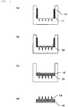
- Fig. 4 illustrates the method for manufacturing a needle-shaped body of the invention.
- Fig. 4 illustrates the method for manufacturing when the needle-shaped body shown in FIG. 3(a) is manufactured.
- the aqueous solutions of the materials that form the projection side layer 16 and the support base side layer 18 are each prepared.
- an intaglio plate 10 with a needle pattern is prepared ( Fig. 4(a) ).
- a method for manufacturing an original plate that determines a shape of the needle-shaped body a known method for manufacturing can appropriately be used in accordance with the shape of the needle-shaped body.
- a technique of microfabrication may be used to form the original plate, and as the technique of microfabrication, for example, a lithography method, a wet etching method, a dry etching method, a sandblast method, a laser machining method, a precision machining method, or the like may be used.
- a known shape transfer method may appropriately be used. For example, (1) forming the intaglio plate of Ni by a Ni electroforming method, (2) transfer molding by using a molten resin, or the like can be raised.
- the intaglio plate 10 is supplied with an aqueous solution 16' of a material that forms the projection side layer.
- a solvent for the aqueous solution 16' of the material that forms the projection side layer only needs to be a solvent that dissolves the material of the needle-shaped body, and water is used therefor. Noted that another constituent of the solvent, such as alcohol, may be added to water.
- heat drying may be performed in some cases. It is possible by performing the heat drying to suppress mixture in the vicinity of an interface with an aqueous solution 18' of a material that forms the support base side layer and is filled next. Especially when the aqueous solution 18' of the material that forms the support base side layer has the greater specific gravity than the aqueous solution 16' of the material that forms the projection side layer, the heat drying should be performed.
- the aqueous solution 18' of the material that forms the support base side layer is supplied on top of the projection side layer 16.
- a solvent for the aqueous solution 18' of the material that forms the support base side layer only needs to be a solvent that dissolves the material of the needle-shaped body, and water is used therefor. Noted that another constituent of the solvent, such as alcohol, may be added to water.
- the aqueous solution 16' of the material that forms the projection side layer and the aqueous solution 18' of the material that forms the support base side layer are the liquid-liquid dispersion system in which the aqueous solution 16' and the aqueous solution 18' are not mixed with each other.
- the aqueous solution 16' of the material that forms the projection side layer desirably has the greater specific gravity than the aqueous solution 18' of the material that forms the support base side layer.
- the aqueous solution 16' of the material that forms the projection side layer and the aqueous solution 18' of the material that forms the support base side layer are the liquid-liquid dispersion system in which the aqueous solution 16' and the aqueous solution 18' are not mixed with each other, and the aqueous solution 16' of the material that forms the projection side layer can have the greater specific gravity than the aqueous solution 18' of the material that forms the support base side layer.
- the aqueous solution 16' of the material that forms the projection side layer and the aqueous solution 18' of the material that forms the support base side layer being selected from a pullulan solution and a dextran solution and the aqueous solution 18' being selected from a hydroxypropyl cellulose solution, a hydroxyethyl cellulose solution, a methyl cellulose solution, and a hydroxypropyl methylcellulose solution.
- a known method may appropriately be selected in accordance with a shape and dimensions of the intaglio plate.
- a spin coating method, an ink jet method, a method for using a dispenser, a casting method, or the like may be used as the method for supplying the aqueous solution.
- an environment around the intaglio plate may be placed under reduced pressure or under vacuum.
- the aqueous solution 18' of the material that forms the support base side layer is dried and hardened.
- a drying method may appropriately be selected in accordance with the environment, such as natural drying, bottom surface heating with a hot plate, and drying by hot air drying. Noted that a drying needs to be performed at a temperature at which the aqueous solution is not boiled. The drying temperature is preferably performed at the temperature that is at least 110°C or lower.
- the needle-shaped body 1 can be obtained when being peeled from the intaglio plate 10 after completion of drying. Since the aqueous solution 16' of the material that forms the projection side layer and the aqueous solution 18' of the material that forms the support base side layer form the liquid-liquid dispersion system in which the aqueous solution 16' and the aqueous solution 18' are not mixed with each other, the aqueous solution 16' of the material that forms the projection side layer and the aqueous solution 18' of the material that forms the support base side layer are dried while keeping a double-layered state. Thus, the needle-shaped body having a double-layered structure can be obtained.
- Fig. 5 illustrates the method for manufacturing a needle-shaped body of the invention.
- Fig. 5 illustrates the method for manufacturing when the needle-shaped body shown in FIG. 3(b) is manufactured.
- a second plate 11 is prepared that is detachable and can surround an outer edge of a portion of the intaglio plate, the portion corresponding to the support base.
- the aqueous solution 16' of the material that forms the projection side layer is supplied to the intaglio plate 10. Then, the aqueous solution in the intaglio plate is dried.
- the heat drying is preferred as drying, and it is possible by performing drying to suppress the mixture in the vicinity of the interface with the aqueous solution 18' of the material that forms the support base side layer and is filled next.
- the second plate 11 is detached from the intaglio plate. After the removal of the second plate from the intaglio plate, as shown in Fig. 5 (c) , the aqueous solution 18' of the material that forms the support base side layer is supplied on the top of the projection side layer 16. Then, the aqueous solution 18' of the material that forms the support base side layer is dried and hardened.
- the needle-shaped body shown in Fig. 5(d) is obtained when being peeled from the intaglio plate 10 after the completion of drying.
- Fig. 6 illustrates the method for manufacturing a needle-shaped body of the invention.
- Fig. 6 illustrates the method for manufacturing when the needle-shaped body shown in FIG. 3(d) is manufactured.
- the intaglio plate 10 with the needle pattern is prepared ( Fig. 6(a) ).
- the aqueous solution 16' of the material that forms the projection side layer is supplied to the intaglio plate 10.
- the aqueous solution 16' of the material that forms the projection side layer is supplied by the ink jet method to a portion of the intaglio plate that corresponds to the projection.
- the aqueous solution 16' of the material that forms the projection side layer is discharged from an ink jet nozzle 14. Then, the aqueous solution in the intaglio plate is dried.
- the heat drying is preferred as drying, and it is possible by performing drying to suppress the mixture in the vicinity of the interface with the aqueous solution 18' of the material that forms the support base side layer and is filled next.
- the aqueous solution 18' of the material that forms the support base side layer is supplied on the top of the projection side layer 16.
- the aqueous solution 18' of the material that forms the support base side layer is dried and hardened.
- the needle-shaped body shown in Fig. 6(d) is obtained when being peeled from the intaglio plate 10 after the completion of drying.
- the ink jet method can favorably be used as a means for supplying the aqueous solution 16' of the material that forms the projection side layer to the intaglio plate 10. It is possible by using the ink jet method to significantly reduce usage of the expensive delivery agent.
- Fig. 7 illustrates the method for puncturing the skin with the needle-shaped body of the invention.
- the needle-shaped body that includes the projection side layer 16 and the support base side layer 18 of the invention is prepared ( Fig. 7(a) ).
- the needle-shaped body of the invention punctures a skin S ( Fig. 7(b) ).
- the needle-shaped body of the invention is peeled at the interface between the projection side layer 16 and the support base side layer 18 ( Fig. 7(c) ).
- the projection side layer and the support base side layer can easily be peeled. Accordingly, after the needle-shaped body punctures the skin, only the support base side layer can be peeled from the skin in the state that the projection side layer is in contact with the skin. Thus, the needle-shaped body that punctures the skin cannot easily be recognized.
- Fig. 8 illustrates the method for puncturing the skin with the needle-shaped body of the invention (another aspect) .
- an adhesive tape 2 is adhered to the support base side of the needle-shaped body of the invention that includes the projection side layer 16 and the support base side layer 18.
- the adhesive tape 2 includes an adhesive layer 21 on top of a base 22.
- the needle-shaped body that is fixed to the adhesive tape 2 punctures the skin S ( Fig. 8 (b) ) .
- the needle-shaped body of the invention is peeled at the interface between the projection side layer 16 and the support base side layer 18 ( Fig. 8(c) ).
- the needle-shaped body in the method for puncturing the skin by using the needle-shaped body of the invention, after the needle-shaped body punctures the skin S ( Fig. 8(b) ), the needle-shaped body can be adhered to the skin and retained so by the adhesive layer of the adhesive tape in a state that the needle-shaped body punctures the skin, and then the needle-shaped body of the invention can be peeled at the interface between the projection side layer 16 and the support base side layer 18 ( Fig. 8(c) ).
- the needle-shaped body shown in Fig. 3(a) was produced by the following method.
- the needle-shaped body shown in Fig. 3(a) is produced by the following method.
- the needle-shaped body shown in Fig. 3(a) is produced by the following method.
- the needle-shaped body shown in Fig. 3(a) is produced by the following method.
- the needle-shaped body shown in Fig. 3(a) is produced by the following method.
- the needle-shaped body is produced by the following method.
- the needle-shaped body is produced by the following method.
- the needle-shaped body is produced by the following method.
- the two aqueous solutions that were used in the methods of manufacturing a needle-shaped body in Example 1 to Example 5 and Comparative Example 1 to Comparative Example 3 were poured into a beaker and left for five minutes, and states of the aqueous solutions in the beaker were confirmed.
- a condition (an interface) that each of the aqueous solutions was separated in an upper part or a lower part in the beaker was confirmed, and each of the aqueous solutions was confirmed to be the liquid-liquid dispersion system.
- the condition (the interface) of separation in the upper part and the lower part was not confirmed.
- Each of the needle-shaped bodies of Example 1 to Example 5 and Comparative Example 1 to Comparative Example 3 was cut perpendicular to the support base, and a cross section thereof was observed with a scanning electron microscope.
- Each of Examples 1 to 5 had the double-layered structure. It was observed in Comparative Example 3 that sodium alginate and pullulan were mixed at the interface between the projection side layer and the support base side layer. Although the double-layered structure was confirmed in Example 4, it was observed that hydroxypropyl cellulose and pullulan were partially mixed at the interface between the projection side layer and the support base side layer.
- Each of Comparative Example 1 and Comparative Example 2 had a single-layered structure, and the interface was not observed therein.
- Adhesion strength between the projection side layer and the support base side layer was measured by referring to Japanese Industrial Standards JIS K6854-1 (1999) "Adhesives - Peel test for a flexible-bonded-to-rigid test specimen assembly - Part 1: 90° peel".
- the needle-shaped body which was peeled from the intaglio plate, was sliced into a strip of 15 mm in width. A portion of the needle-shaped body sliced into the strip was peeled into the projection side layer and the support base side layer, and ends of the strip were fixed to a grasp portion of a tensile test machine. At this time, the ends were fixed for 90 degree peeling.
- Example 4 Since the aqueous solution on the projection side layer, which was filled in the intaglio plate, was dried in Example 1 to Example 3 and Example 5, the molded needle-shaped body obtained the double-layered structure in which the interface was clearly confirmed.
- Example 4 in which the aqueous solution on the projection side layer was not dried after being filled, although the molded needle-shaped body obtained the double-layered structure, it was confirmed that the materials were partially mixed at the interface between the projection side layer and the support base side layer.
- the peeling strength between the two layers was slightly higher than that in Example 1 and required a force of 1.5 N/15 mm in width.
- the needle-shaped body of the invention can be used in various fields where the fine needle-shaped body is needed.
- the needle-shaped body can be expected in application in a MEMS device, an optical member, a sample jig, drug development, medical practice, the cosmetic product, the beauty application, and the like.
Description
- The present invention relates to a method for manufacturing a needle-shaped body and a needle-shaped body.
- A transdermal absorption method as a method for penetrating a delivery agent such as a medicine from a skin surface and administering the delivery agent into a body has been used as a method that enables easy administration of the delivery agent without causing any pain to a human body.
- In the field of transdermal administration, a method for perforating the skin by using a needle-shaped body that is formed with a needle of µm order and administering a medicine or the like into the skin has been suggested (see PTL 1).
- In addition, as a method for manufacturing a needle-shaped body, it has been suggested to produce an original plate by machining, form a transfer plate from the original plate, and perform transfer molding by using the transfer plate (see PTL 2).
- Furthermore, as the method for manufacturing a needle-shaped body, it has been suggested to produce the original plate by an etching method, form the transfer plate from the original plate, and perform the transfer molding by using the transfer plate (see PTL 3).
- Moreover, as a material for constituting the needle-shaped body, a material is desired that does not cause a harmful effect on the human body even when the damaged needle-shaped body remains in the body. As such a material, a biocompatible material, such as chitin or chitosan, has been suggested (see PTL 4).
-
- PTL 1:
JP-A-48-93192 - PTL 2:
WO 2008/013282 - PTL 3:
WO 2008/004597 - PTL 4:
WO 2008/020632 -
US2011276028 (A1 ) discloses a method and a drug delivery system for transdermally administering parathyroid hormone (PTH) in a pulsatile fashion, where the drug delivery system comprises an array of microprojections each comprising PTH. -
WO2009048607 (A1 ) describes a microprojection array comprising an approximately planar base and a plurality of microprojections, wherein the array comprises a vaccine and a polymeric material. The array may have multiple layers. The vaccine may be placed in only one layer. -
JP2010233674 (A microneedle sheet 10 used by sticking biodegradable needles 12 supported to the surface of thesheet 14 into the skin, a proximal section 12B close to thesheet 14, of each needle 12 is formed to be more fragile than the distal section 12A and is configured to have such fragility as to be broken by force pulling thesheet 14 along the skin surface, with the needle 12 being stuck into theskin 16. -
WO2011135531 (A2 ) discloses medical devices. In addition to one or more siRNA constructs, devices include nanostructures fabricated on a surface to form a nanotopography. A random or non-random pattern of structures may be fabricated such as a complex pattern including structures of differing sizes and/or shapes. Microneedles may be incorporated on devices. The pattern including nanostructures may be formed on the surface of the microneedles. -
EP2441437 (A1 ) describes amicroneedle device 1 being arranged so that at least a part of amicroneedle array 2 provided with microneedles 3 made from polylactic acid having a weight average molecular weight of 40,000 or more is coated with a carrier containing physiologically active ingredients. - When such a biocompatible material is used to produce the needle-shaped body, it is common to produce the needle-shaped body by removing a solvent from a solution of the material by a method such as drying. As for the needle-shaped body of a dissolved type, a needle portion of which contains the delivery agent and is dissolved in the skin after the skin is punctured with the needle-shaped body, the needle-shaped body needs to be adhered to the skin for a certain time period, which causes a problem in appearance. The problem has especially been serious when a face is punctured with the needle-shaped body.
- The present invention addresses a problem by providing a method for manufacturing a needle-shaped body and a needle-shaped body to solve the problem.
- In order to solve the above problem, the invention according to
claim 1 is a method for manufacturing a needle-shaped body that includes a needle-shaped projection and a support base for supporting the projection. - Further beneficial embodiments of the method of the present invention as well as the needle-shaped body of the present invention are disclosed in the enclosed set of claims.
- In the needle-shaped body of a double-layered structure that can be obtained by the method for manufacturing a needle-shaped body of the invention, the projection side layer and the support base side layer can easily be peeled. Accordingly, after the needle-shaped body punctures the skin, only the support base side layer can be peeled from the skin in a state that the projection side layer is in contact with the skin. Thus, the needle-shaped body that punctures the skin cannot easily be recognized.
-
- [
Fig. 1] Fig. 1 is a perspective view of a needle-shaped body of the invention. - [
Fig. 2] Fig. 2 is a schematic cross-sectional view of the needle-shaped body of the invention. - [
Fig. 3] Fig. 3 is a schematic cross-sectional view of the needle-shaped body of the invention. - [
Fig. 4] Fig. 4 illustrates a method for manufacturing a needle-shaped body of the invention, and illustrates a method for manufacturing when a needle-shaped body shown inFIG. 3 (a) is manufactured. - [
Fig. 5] Fig. 5 illustrates the method for manufacturing a needle-shaped body of the invention, and illustrates the method for manufacturing when a needle-shaped body shown inFIG. 3(b) is manufactured. - [
Fig. 6] Fig. 6 illustrates the method for manufacturing a needle-shaped body of the invention, and illustrates the method for manufacturing when a needle-shaped body shown inFIG. 3(d) is manufactured. - [
Fig. 7] Fig. 7 illustrates a method for puncturing a skin with the needle-shaped body of the invention. - [
Fig. 8] Fig. 8 illustrates the method for puncturing the skin with the needle-shaped body of the invention (another aspect). - A method for manufacturing a needle-shaped body of the invention is a method for manufacturing a needle-shaped body that includes a needle-shaped projection and a support base for supporting the projection, the method for manufacturing is defined in
claim 1. - With the method for manufacturing a needle-shaped body in this configuration, peeling strength between a projection side layer and a support base side layer of the obtained needle-shaped body can be low, and only the support base side layer can be peeled from a skin in a state that the projection side layer is in contact with the skin after the skin is punctured with the needle-shaped body.
- In addition, in the method for manufacturing a needle-shaped body of the invention, the peeling strength between the projection side layer and the support base side layer is preferably 8 N/15 mm in width or lower. Since the peeling strength is set to fall within the above range, only the support base side layer can be peeled from the skin in the state that the projection side layer is in contact with the skin after the skin is punctured with the needle-shaped body.
- In addition, the method for manufacturing a needle-shaped body of the invention preferably includes a process of drying the aqueous solution of the material forming a projection-side-layer in the intaglio plate after the process of supplying the aqueous solution of the material forming a projection-side-layer to the intaglio plate and before the process of supplying the aqueous solution of the material forming a support-base-side-layer to the intaglio plate.
- The drying process is provided after the process of supplying the aqueous solution of the material forming a projection-side-layer. Accordingly, compared to a method for manufacturing a needle-shaped body in which the process of supplying the aqueous solution of the material forming a support-base-side-layer to the intaglio plate is performed without drying after the process of supplying the aqueous solution of the material forming a projection-side-layer to the intaglio plate, the method for manufacturing a needle-shaped body can lower the peeling strength between the projection side layer and the support base side layer of the obtained needle-shaped body.
- In addition, in the method for manufacturing a needle-shaped body of the invention, specific gravity of the aqueous solution of the material forming a projection-side-layer is preferably greater than specific gravity of the aqueous solution of the material forming a support-base-side-layer. By establishing the above magnitude relationship, the peeling strength between the projection side layer and the support base side layer of the obtained needle-shaped body can be low. Especially, in the case where the process of supplying the aqueous solution of the material forming a support-base-side-layer to the intaglio plate is performed without drying after the process of supplying the aqueous solution of the material forming a projection-side-layer to the intaglio plate, so as to manufacture the needle-shaped body, a relation in the specific gravity of the two aqueous solutions is preferably set to the above magnitude relationship. On the other hand, in the case where the drying process is provided after the process of supplying the aqueous solution of the material forming a projection-side-layer, the peeling strength between the projection side layer and the support base side layer of the obtained needle-shaped body can be low even when the specific gravity of the two aqueous solutions does not satisfy the above magnitude relationship.
- In addition, in the method for manufacturing a needle-shaped body of the invention, it is preferred that the material forming a projection-side-layer contains a material selected from pullulan and dextran, and the material forming a support-base-side-layer contains a material selected from hydroxypropyl cellulose, hydroxyethyl cellulose, methyl cellulose, and hydroxypropyl methyl cellulose. Since the material for forming the each layer is selected from the above materials, the aqueous solution of the material forming a projection-side-layer and the aqueous solution of the material forming a support-base-side-layer can be a liquid-liquid dispersion system, and the peeling strength between the projection side layer and the support base side layer of the obtained needle-shaped body can be low.
- Furthermore, the needle-shaped body of the invention is a needle-shaped body that includes the needle-shaped projection and the support base for supporting the projection, and is defined in the independent product claim of the set of claims. Since the peeling strength is set to fall within the above range, only the support base side layer can easily be peeled from the skin in the state that the projection side layer is in contact with the skin after the skin is punctured with the needle-shaped body.
- Moreover, the needle-shaped body of the invention is the needle-shaped body as defined in the independent product claim in the set of claims, that includes the needle-shaped projection and the support base for supporting the projection, and is characterized by including the at least two layers of the projection side layer and the support base side layer, in that the material forming a projection-side-layer contains the material selected from the group of pullulan and dextran and that the material forming a support-base-side-layer contains the material selected from the group of hydroxypropyl cellulose, hydroxyethyl cellulose, methyl cellulose, and hydroxypropyl methylcellulose. As for the needle-shaped body selected from and formed of any of these materials, the peeling strength between the projection side layer and the support base side layer of the obtained needle-shaped body can be low, and only the support base side layer can be peeled from the skin in the state that the projection side layer is in contact with the skin after the skin is punctured with the needle-shaped body.
- A detailed description will be made on an embodiment of the invention by using the drawings. First, a structure and a material of a needle-shaped body of the invention will be described, and then a method for manufacturing the needle-shaped body will be described.
-
FIG. 1 is a perspective view of the needle-shaped body of the invention.FIG. 2 is a schematic view of the needle-shaped body of the invention. Note that the needle-shaped body of the invention is characterized by including the at least two layers of the projection side layer and the support base side layer; however, neither the projection side layer nor the support base side layer is shown in the needle-shaped body shown inFig. 1 andFig. 2 . - The needle-shaped body of the invention represents a molded body that is formed of a
support base 32 and aprojection 34. A shape of the projection only needs to be a shape that is suitable to puncture the skin, and can appropriately be designed. More specifically, the shape of the projection may be a circular cone, a pyramid, a cylinder, a prism, a pencil shape (with a cylinder-shaped body and a conical-shaped tip), or the like. In addition, either (1) a shape with the one projection on the support base, or (2) a shape with the plural projections erected on the support base can be adopted. - In addition, when the plural projections are erected on the support base, the each projection is preferably arranged in an array. Here, the "array" indicates a state that the needle-shaped unit body is arranged, and includes patterns such as lattice arrangement, close packing arrangement, concentric arrangement, and random arrangement, for example.
-
Fig. 2 (a) is a top view from the projection side of the needle-shaped body, andFig. 2(b) is a cross-sectional view taken along an I-I' surface of the needle-shaped body inFig. 2(a) . - In a needle-shaped
body 1 of the invention, dimensions of the needle-shapedprojection 34 preferably have thinness and a length that are suitable for forming a puncture hole in the skin. More specifically, a height H of theprojection 34 shown inFig. 2 is preferably within a range from 10 µm to 1,000 µm inclusive. The height H of the projection is a distance from thesupport base 32 to a tip of theprojection 34. - The height H of the projection is preferably determined in consideration of how deep the puncture hole, which is formed when the needle-shaped body punctures within the above range, is formed in the skin.
- Particularly, when the puncture hole, which is formed when the needle-shaped body punctures, is retained in "a horny layer", the height H of the projection of the needle-shaped body desirably falls within a range of 10 µm to 300 µm inclusive, for example, and more preferably, of 30 µm to 200 µm inclusive.
- In addition, when the puncture hole, which is formed when the needle-shaped body punctures, is retained "in a length that penetrates the horny layer but does not reach a neural layer", the height H of the projection of the needle-shaped body desirably falls within a range of 200 µm to 700 µm inclusive, more preferably, of 200 µm to 500 µm inclusive, and further preferably, of 200 µm to 300 µm inclusive.
- Furthermore, when the puncture hole, which is formed when the needle-shaped body punctures, has a "length that allows the puncture hole to reach a corium", the height H of the projection of the needle-shaped body preferably falls within a range of 200 µm to 500 µm inclusive. Moreover, when the puncture hole, which is formed when the needle-shaped body punctures, has a "length that allows the puncture hole to reach epidermis", the height H of the projection of the needle-shaped body preferably falls within a range of 200 µm to 300 µm inclusive.
- A width D of the projection preferably falls within a range of 1 µm to 300 µm inclusive. The width D of the projection is preferably determined in consideration of how deep the puncture hole, which is formed when the needle-shaped body punctures within the above range, is formed in the skin, or the like.
- The width D of the projection is a maximum length of a length of the projection that is in contact with the support base when the projection is projected in parallel with a base surface. For example, when the projection is in a shape of the circular cone, a diameter of a circle on a surface on which the projection and the support base contact each other corresponds to the width D. When the projection is in a shape of a square pyramid, a diagonal line of a square on the surface on which the projection and the support base contact each other corresponds to the width D. In addition, when the projection is in a shape of the cylinder, a diameter of a circle on a surface on which the projection and the support base contact each other corresponds to the width D. When the projection is in a shape of a square prism, a diagonal line of a square on the surface on which the projection and the support base contact each other corresponds to the width D.
- An aspect ratio preferably falls within a range from 1 to 10 inclusive. An aspect ratio A is defined by using the height H and the width D of the projection as A = H/D.
- In the needle-shaped body according to the embodiment, when the projection has a tip angle as in a conical shape and penetrates the horny layer, a tip angle θ of the projection desirably falls within a range from 5° to 30° inclusive, and more preferably, of 10° to 20° inclusive. Noted that the tip angle θ represents the maximum angle of angles (apex angles) when the projection is projected in parallel with the support base surface.
-
Fig. 3 is a schematic cross-sectional view of the needle-shaped body of the invention. The needle-shaped body of the invention is characterized by including the at least two layers of the projection side layer and the support base side layer and in that the projection side layer and the support base side layer are formed of different constituents. - In the needle-shaped body of the invention illustrated in
Fig. 3(a) , aprojection side layer 16 and a supportbase side layer 18 are separated from each other in thesupport base 32. - In the needle-shaped body of the invention illustrated in
Fig. 3(b) , theprojection side layer 16 and the supportbase side layer 18 are separated from each other in thesupport base 32, and theprojection side layer 16 in thesupport base 32 is further formed to have a smaller area than an outer shape of the support base. - In the needle-shaped body of the invention illustrated in
Fig. 3 (c) , theprojection side layer 16 and the supportbase side layer 18 are separated from each other at a joined position of thesupport base 32 and theprojection 34. - In the needle-shaped body of the invention illustrated in
Fig. 3 (d) , theprojection side layer 16 and the supportbase side layer 18 are separated from each other in theprojection 34. - The needle-shaped body of the invention is characterized that the peeling strength between the
projection side layer 16 and the supportbase side layer 18 is 8 N/15 mm in width or lower, the peeling strength being measured by following Japanese Industrial Standards JIS K6854-1 (1999) "Adhesives - Peel test for a flexible-bonded-to-rigid test specimen assembly - Part 1: 90° peel" . The peeling strength between the projection side layer and the support base side layer is set to 8 N/15 mm in width or lower, so that both of the layers can easily be peeled. Accordingly, after the needle-shaped body punctures the skin, only the support base side layer can be peeled from the skin in a state that the projection side layer is in contact with the skin. Thus, the needle-shaped body that punctures the skin cannot easily be recognized. Therefore, a problem in appearance during use can be improved. Especially, the needle-shaped bodies inFigs. 3(b), (c), (d) can each have a profound effect of the invention. - Furthermore, in the needle-shaped body of the invention, the peeling strength between the
projection side layer 16 and the supportbase side layer 18 is preferably from 0.5 N/15 mm in width to 8 N/15 mm in width inclusive. When the peeling strength is lower than 0.5 N/15 mm in width, the needle-shaped body may not be favorably peeled from the intaglio plate. More preferably, the peeling strength between theprojection side layer 16 and the supportbase side layer 18 is from 1 N/15 mm in width to 3 N/15 mm in width inclusive. - In the needle-shaped body of the invention, a material for constituting the
projection side layer 16 is defined in the independent product claim in the set of claims. Biodegradable polysaccharides include, for example, dextran, dextrin, pectin, pullulan, chondroitin sulfate, alginate, chitosan, carboxymethyl cellulose, hydroxymethyl cellulose, hydroxyethyl cellulose, hydroxypropyl cellulose, methyl cellulose, ethyl cellulose, and the like. In addition, the material may be a mixture of these biodegradable polysaccharides and contains a material selected from pullulan and dextran. Since the biodegradable polysaccharide is used as theprojection side layer 16, theprojection side layer 16 can be dissolved in the skin after the needle-shaped body punctures the skin. Thus, when the projection side layer contains a medicinal property, the delivery agent can promptly be introduced into the skin. - A material for constituting the support
base side layer 18 is defined in the independent product claim in the set of claims. A material that is a polysaccharide and has flexibility includes for example dextran, dextrin, pectin, pullulan, chondroitin sulfate, alginate, chitosan, carboxymethyl cellulose, hydroxymethyl cellulose, hydroxyethyl cellulose, hydroxypropyl cellulose, methyl cellulose, ethyl cellulose, and the like. In addition, the material may be a mixture of these biodegradable polysaccharides and includes the material as defined in the independent product claim in the set of claims. - Among them, pullulan and/or dextran is used as the material for constituting the
projection side layer 16 and a material selected from hydroxypropyl cellulose, hydroxyethyl cellulose, methyl cellulose, hydroxypropyl methylcellulose is used as the material for constituting the supportbase side layer 18. The reason is because the peeling strength between the projection side layer and the support base side layer can easily be set to 8 N/15 mm in width or lower. This is because a combination of aqueous solutions of the materials becomes the liquid-liquid dispersion system and also because the aqueous solution of the material for constituting theprojection side layer 16 has the greater specific gravity than the aqueous solution of the material for constituting the supportbase side layer 18. - The needle-shaped body of the invention can contain the delivery agent to be delivered into the skin. As the delivery agent, a pharmacologically active substance or a cosmetic delivery agent can be contained. At this time, when a material with a fragrance is used as the delivery agent, the aroma can be applied upon use, and thus can preferably be used as a beauty product.
- The pharmacologically active substance can appropriately be selected according to its application. For example, the pharmacologically active substance may be a vaccine for influenza or the like, a medicine suitable as a painkiller for cancer patients, insulin, a biopharmaceutical, a gene therapy medicine, an injection, an oral medicine, a preparation for application to the skin, or the like. Since the needle-shaped body of the invention punctures the skin, in addition to the pharmacologically active substance that is used for the conventional transdermal administration, the needle-shaped body of the invention can be applied for the pharmacologically active substance that requires a subcutaneous injection. Particularly, as for the vaccine as the injection and the like, since there is no pain during administration when the needle-shaped body is used, use of the needle-shaped body is suitable for children. In addition, as for conventional administration of the oral medicine, a child has a difficulty in swallowing the oral medicine. Since there is no need to swallow the medicine during administration when the needle-shaped body is used, the use of the needle-shaped body is suitable for children.
- In the needle-shaped body of the dissolved type in which a needle that has punctured is eluted in the skin and delivers the delivery agent in the body, the delivery agent is contained in the needle-shaped body. However, there has been a problem that a medicine that is not eluted in the skin but remains in the support base of the needle-shaped body is wasted. A waste of the medicine can be solved by containing the delivery agent only in the projection side layer.
- The cosmetic delivery is a composition used as a cosmetic product and the beauty product. For example, a moisturizer, a colorant, a perfume, a physiologically active substance that shows a beauty effect (an improvement effect on wrinkles, blemishes, stretch marks, or the like, an improvement effect on hair loss, or the like) or the like can be raised.
- In addition, particularly, when a depth of the puncture hole is retained "in the horny layer", the delivery agent can be retained in the horny layer. Since the horny layer is constantly and newly produced due to metabolism, the delivery agent in the horny layer is eliminated from the body over time. Thus, the delivery agent can be eliminated by cleansing the skin, peeling the skin, or the like.
- Furthermore, when the puncture hole is retained in "the length that penetrates the horny layer but does not reach the neural layer", the delivery agent can be delivered to a position deeper than the horny layer. Since the puncture hole formed in the horny layer is mended over time, the delivery agent that is delivered under the horny layer is retained in a living body in a state of being barriered against the outside by the horny layer. Accordingly, the delivery agent can be retained for a long time period since an opportunity of the peeling thereof due to metabolism of the horny layer or cleansing in the skin care can be reduced.
- Thus, when the delivery agent used for beauty application, a long-term cosmetic condition can be maintained. Therefore, the needle-shaped body of the invention can favorably be used to deliver the cosmetic delivery agent to a portion where long-term retention of a color is desired, particularly, eyebrows, areas around eyes, an area around lips, or the like.
- Moreover, the needle-shaped body of the invention can favorably be used for a medical direction (makeup, a treatment, or the like) for abnormality of the skin (spotted rash or the like) that is caused by a portion under the horny layer.
- The needle-shaped body of the invention is characterized in that the projection side layer and the support base side layer are formed of different constituents. "(Being) formed of different constituents" indicates that polysaccharides used for the projection side layer and the support base side layer may be different materials or that the same polysaccharide is used for the projection side layer and the support base side layer but other constituents such as the delivery agents may be different materials.
- Noted that, of the needle-shaped body of the invention, a needle-shaped body in which the projection side layer and the support base side layer are not clearly separated and that includes a mixed layer of the projection side layer and the support base side layer between the projection side layer and the support base side layer is not excluded. In the needle-shaped body that includes the mixed layer of the projection side layer and the support base side layer, the peeling strength between the projection side layer and the support base side layer, which will be described below, can be increased.
- The needle-shaped body of the invention can be adopted such that the delivery agent is contained only in the projection side layer and thus is not contained in the support base side layer. The delivery agent can efficiently be used by containing the delivery agent only in the projection side layer.
- Meanwhile, when the delivery agent is administered by using the needle-shaped body, the delivery agent may be applied onto the skin as a subject either before the needle-shaped body punctures the skin or after the needle-shaped body punctures the skin. At this time, the delivery agent may also be arranged in the needle-shaped body, and the delivery agent may be applied to the skin surface as the subject.
- In addition, the needle-shaped body of the invention may include the delivery agent on a surface of the projection.
- Furthermore, in the needle-shaped body of the invention, the support base may have flexibility. Since the support base has the flexibility, the needle-shaped body can favorably puncture the subject with flexibility such as a curved surface or the skin of the living body. When having the flexibility, the support base is formed in a rolled shape. Accordingly, a roller with the erected projection can be formed.
- For the medical direction with use of the needle-shaped body of the invention, an applicator for fixing a position and a direction of insertion may be used.
- Next, a method for manufacturing the needle-shaped body will be described.
-
Fig. 4 illustrates the method for manufacturing a needle-shaped body of the invention.Fig. 4 illustrates the method for manufacturing when the needle-shaped body shown inFIG. 3(a) is manufactured. - The aqueous solutions of the materials that form the
projection side layer 16 and the supportbase side layer 18 are each prepared. - Next, an
intaglio plate 10 with a needle pattern is prepared (Fig. 4(a) ). As a method for manufacturing an original plate that determines a shape of the needle-shaped body, a known method for manufacturing can appropriately be used in accordance with the shape of the needle-shaped body. At this time, a technique of microfabrication may be used to form the original plate, and as the technique of microfabrication, for example, a lithography method, a wet etching method, a dry etching method, a sandblast method, a laser machining method, a precision machining method, or the like may be used. As a method for forming the intaglio plate from the original plate, a known shape transfer method may appropriately be used. For example, (1) forming the intaglio plate of Ni by a Ni electroforming method, (2) transfer molding by using a molten resin, or the like can be raised. - Next, as shown in
FIG. 4(b) , theintaglio plate 10 is supplied with an aqueous solution 16' of a material that forms the projection side layer. A solvent for the aqueous solution 16' of the material that forms the projection side layer only needs to be a solvent that dissolves the material of the needle-shaped body, and water is used therefor. Noted that another constituent of the solvent, such as alcohol, may be added to water. - After the aqueous solution is supplied, heat drying may be performed in some cases. It is possible by performing the heat drying to suppress mixture in the vicinity of an interface with an aqueous solution 18' of a material that forms the support base side layer and is filled next. Especially when the aqueous solution 18' of the material that forms the support base side layer has the greater specific gravity than the aqueous solution 16' of the material that forms the projection side layer, the heat drying should be performed.
- Next, as shown in
Fig. 4(c) , the aqueous solution 18' of the material that forms the support base side layer is supplied on top of theprojection side layer 16. A solvent for the aqueous solution 18' of the material that forms the support base side layer only needs to be a solvent that dissolves the material of the needle-shaped body, and water is used therefor. Noted that another constituent of the solvent, such as alcohol, may be added to water. Particularly, the aqueous solution 16' of the material that forms the projection side layer and the aqueous solution 18' of the material that forms the support base side layer are the liquid-liquid dispersion system in which the aqueous solution 16' and the aqueous solution 18' are not mixed with each other. In addition, the aqueous solution 16' of the material that forms the projection side layer desirably has the greater specific gravity than the aqueous solution 18' of the material that forms the support base side layer. - For example, the aqueous solution 16' of the material that forms the projection side layer and the aqueous solution 18' of the material that forms the support base side layer are the liquid-liquid dispersion system in which the aqueous solution 16' and the aqueous solution 18' are not mixed with each other, and the aqueous solution 16' of the material that forms the projection side layer can have the greater specific gravity than the aqueous solution 18' of the material that forms the support base side layer. On the premise of the above, it is possible to select a combination of the aqueous solution 16' of the material that forms the projection side layer and the aqueous solution 18' of the material that forms the support base side layer, the aqueous solution 16' being selected from a pullulan solution and a dextran solution and the aqueous solution 18' being selected from a hydroxypropyl cellulose solution, a hydroxyethyl cellulose solution, a methyl cellulose solution, and a hydroxypropyl methylcellulose solution.
- For a method for supplying the aqueous solution, a known method may appropriately be selected in accordance with a shape and dimensions of the intaglio plate. For example, as the method for supplying the aqueous solution, a spin coating method, an ink jet method, a method for using a dispenser, a casting method, or the like may be used. In addition, upon filling, an environment around the intaglio plate may be placed under reduced pressure or under vacuum.
- Next, the aqueous solution 18' of the material that forms the support base side layer is dried and hardened. A drying method may appropriately be selected in accordance with the environment, such as natural drying, bottom surface heating with a hot plate, and drying by hot air drying. Noted that a drying needs to be performed at a temperature at which the aqueous solution is not boiled. The drying temperature is preferably performed at the temperature that is at least 110°C or lower.
- The needle-shaped
body 1 can be obtained when being peeled from theintaglio plate 10 after completion of drying. Since the aqueous solution 16' of the material that forms the projection side layer and the aqueous solution 18' of the material that forms the support base side layer form the liquid-liquid dispersion system in which the aqueous solution 16' and the aqueous solution 18' are not mixed with each other, the aqueous solution 16' of the material that forms the projection side layer and the aqueous solution 18' of the material that forms the support base side layer are dried while keeping a double-layered state. Thus, the needle-shaped body having a double-layered structure can be obtained. -
Fig. 5 illustrates the method for manufacturing a needle-shaped body of the invention.Fig. 5 illustrates the method for manufacturing when the needle-shaped body shown inFIG. 3(b) is manufactured. - In
Fig. 5 , when theintaglio plate 10 with the needle pattern is prepared (Fig. 5 (a) ), asecond plate 11 is prepared that is detachable and can surround an outer edge of a portion of the intaglio plate, the portion corresponding to the support base. - Next, as shown in
Fig. 5(b) , the aqueous solution 16' of the material that forms the projection side layer is supplied to theintaglio plate 10. Then, the aqueous solution in the intaglio plate is dried. The heat drying is preferred as drying, and it is possible by performing drying to suppress the mixture in the vicinity of the interface with the aqueous solution 18' of the material that forms the support base side layer and is filled next. Next, thesecond plate 11 is detached from the intaglio plate. After the removal of the second plate from the intaglio plate, as shown inFig. 5 (c) , the aqueous solution 18' of the material that forms the support base side layer is supplied on the top of theprojection side layer 16. Then, the aqueous solution 18' of the material that forms the support base side layer is dried and hardened. The needle-shaped body shown inFig. 5(d) is obtained when being peeled from theintaglio plate 10 after the completion of drying. -
Fig. 6 illustrates the method for manufacturing a needle-shaped body of the invention.Fig. 6 illustrates the method for manufacturing when the needle-shaped body shown inFIG. 3(d) is manufactured. - In
Fig. 6 , theintaglio plate 10 with the needle pattern is prepared (Fig. 6(a) ). Next, as shown inFig. 6(b) , the aqueous solution 16' of the material that forms the projection side layer is supplied to theintaglio plate 10. At this time, the aqueous solution 16' of the material that forms the projection side layer is supplied by the ink jet method to a portion of the intaglio plate that corresponds to the projection. InFig. 6(b) , the aqueous solution 16' of the material that forms the projection side layer is discharged from anink jet nozzle 14. Then, the aqueous solution in the intaglio plate is dried. The heat drying is preferred as drying, and it is possible by performing drying to suppress the mixture in the vicinity of the interface with the aqueous solution 18' of the material that forms the support base side layer and is filled next. Next, as shown inFig. 6 (c) , the aqueous solution 18' of the material that forms the support base side layer is supplied on the top of theprojection side layer 16. Then, the aqueous solution 18' of the material that forms the support base side layer is dried and hardened. The needle-shaped body shown inFig. 6(d) is obtained when being peeled from theintaglio plate 10 after the completion of drying. - When the needle-shaped body in which only the projection includes the projection side layer is manufactured as shown in
Figs. 3(c), (d) , the ink jet method can favorably be used as a means for supplying the aqueous solution 16' of the material that forms the projection side layer to theintaglio plate 10. It is possible by using the ink jet method to significantly reduce usage of the expensive delivery agent. - Next, a method for puncturing the skin with the needle-shaped body of the invention will be described.
-
Fig. 7 illustrates the method for puncturing the skin with the needle-shaped body of the invention. - First, the needle-shaped body that includes the
projection side layer 16 and the supportbase side layer 18 of the invention is prepared (Fig. 7(a) ). Next, the needle-shaped body of the invention punctures a skin S (Fig. 7(b) ). Finally, the needle-shaped body of the invention is peeled at the interface between theprojection side layer 16 and the support base side layer 18 (Fig. 7(c) ). As described above, in the needle-shaped body of the invention, the projection side layer and the support base side layer can easily be peeled. Accordingly, after the needle-shaped body punctures the skin, only the support base side layer can be peeled from the skin in the state that the projection side layer is in contact with the skin. Thus, the needle-shaped body that punctures the skin cannot easily be recognized. -
Fig. 8 illustrates the method for puncturing the skin with the needle-shaped body of the invention (another aspect) . - First, an
adhesive tape 2 is adhered to the support base side of the needle-shaped body of the invention that includes theprojection side layer 16 and the supportbase side layer 18. Theadhesive tape 2 includes anadhesive layer 21 on top of abase 22. (Fig. 8 (a) ) Next, the needle-shaped body that is fixed to theadhesive tape 2 punctures the skin S (Fig. 8 (b) ) . Finally, the needle-shaped body of the invention is peeled at the interface between theprojection side layer 16 and the support base side layer 18 (Fig. 8(c) ). - Noted that, in the method for puncturing the skin by using the needle-shaped body of the invention, after the needle-shaped body punctures the skin S (
Fig. 8(b) ), the needle-shaped body can be adhered to the skin and retained so by the adhesive layer of the adhesive tape in a state that the needle-shaped body punctures the skin, and then the needle-shaped body of the invention can be peeled at the interface between theprojection side layer 16 and the support base side layer 18 (Fig. 8(c) ). - The invention will hereinafter be described in detail by using examples and comparative examples; however, the invention is not limited to these embodiments.
- The needle-shaped body shown in
Fig. 3(a) was produced by the following method. - (1) First, an original plate of the needle-shaped body was formed by using precision machining, the original plate having 36 square pyramids (a bottom surface of 38 µm x 38 µm, a height of 120 µm) arranged in a lattice pattern of six rows and six columns at 1 mm intervals on a silicon base. Next, a nickel film of 500 µm in thickness is formed by plating on the original plate of the needle-shaped body, which is formed of the silicon base. Wet etching is performed to remove the silicon base by a potassium hydroxide solution of 30wt% concentration that is heated to 90°C, so as to produce an intaglio plate formed of nickel.
- (2) A pullulan (Tokyo Chemical Industry Co., Ltd.) solution of 10 wt.% and a hydroxypropyl cellulose (Tokyo Chemical Industry Co., Ltd.) solution of 10 wt.% were prepared.
- (3) The spin coating method was used to fill the produced intaglio plate with the pullulan solution.
- (4) The intaglio plate filled in with the pullulan solution was placed on a hot plate set at 90°C and dried for 30 minutes to evaporate moisture.
- (5) The spin coating method was used to apply the hydroxypropyl cellulose solution onto the intaglio plate, in which a layer formed of pullulan was formed.
- (6) The intaglio plate was dried at a room temperature to form the needle-shaped body.
- (7) The needle-shaped body was peeled from the intaglio plate.
- The needle-shaped body shown in
Fig. 3(a) is produced by the following method. - (1) First, the intaglio plate that is formed of nickel and is the same as Example 1 was produced.
- (2) The pullulan (Tokyo Chemical Industry Co., Ltd.) solution of 10 wt.% and a methyl cellulose (Tokyo Chemical Industry Co., Ltd.) solution of 1 wt.% were prepared.
- (3) The spin coating method was used to fill the produced intaglio plate with the pullulan solution.
- (4) The intaglio plate filled in with the pullulan solution was placed on the hot plate set at 90°C and dried for 30 minutes to evaporate the moisture.
- (5) The spin coating method was used to apply the methyl cellulose solution onto the intaglio plate, in which the layer formed of pullulan was formed.
- (6) The intaglio plate was dried at the room temperature to form the needle-shaped body.
- (7) The needle-shaped body was peeled from the intaglio plate.
- The needle-shaped body shown in
Fig. 3(a) is produced by the following method. - (1) First, the intaglio plate that is formed of nickel and is the same as Example 1 was produced.
- (2) The pullulan (Tokyo Chemical Industry Co., Ltd.) solution of 10 wt.% and a hydroxyethyl cellulose (Tokyo Chemical Industry Co., Ltd.) solution of 10 wt.% were prepared.
- (3) The ink jet method was used to fill the produced intaglio plate with the pullulan solution.
- (4) The intaglio plate filled in with the pullulan solution was placed on the hot plate set at 90°C and dried for 30 minutes to evaporate the moisture.
- (5) The spin coating method was used to apply the hydroxyethyl cellulose solution onto the intaglio plate, in which the layer formed of pullulan was formed.
- (6) The intaglio plate was dried at the room temperature to form the needle-shaped body.
- (7) The needle-shaped body was peeled from the intaglio plate.
- The needle-shaped body shown in
Fig. 3(a) is produced by the following method. - (1) First, the intaglio plate that is formed of nickel and is the same as Example 1 was produced.
- (2) The pullulan (Tokyo Chemical Industry Co., Ltd.) solution of 10 wt.% and a hydroxypropyl cellulose (Tokyo Chemical Industry Co., Ltd.) solution of 10 wt.% were prepared.
- (3) The spin coating method was used to fill the produced intaglio plate with the pullulan solution.
- (4) The spin coating method was used to apply the hydroxypropyl cellulose solution onto the intaglio plate, which was filled in with the pullulan solution, without drying the pullulan solution filled in the intaglio plate.
- (5) The intaglio plate was dried at the room temperature.
- (6) The needle-shaped body was peeled from the intaglio plate of (5).
- The needle-shaped body shown in
Fig. 3(a) is produced by the following method. - (1) First, the intaglio plate that is formed of nickel and is the same as Example 1 was produced.
- (2) A dextran (Tokyo Chemical Industry Co., Ltd.) solution of 10 wt.% and the hydroxypropyl cellulose (Tokyo Chemical Industry Co., Ltd.) solution of 10 wt.% were prepared.
- (3) The spin coating method was used to fill the produced intaglio plate with the dextran solution.
- (4) The spin coating method was used to apply the hydroxypropyl cellulose solution onto the intaglio plate, which was filled in with the dextran solution, without drying the dextran solution filled in the intaglio plate.
- (5) The intaglio plate was dried at the room temperature.
- (6) The needle-shaped body was peeled from the intaglio plate of (5).
- The needle-shaped body is produced by the following method.
- (1) First, the intaglio plate that is formed of nickel and is the same as Example 1 was produced.
- (2) The hydroxypropyl cellulose (Tokyo Chemical Industry Co., Ltd.) solution of 10 wt.% was prepared.
- (3) The spin coating method was used to fill the produced intaglio plate with the hydroxypropyl cellulose solution.
- (4) The intaglio plate filled in with the hydroxypropyl cellulose solution was placed on the hot plate set at 90°C and dried for 30 minutes to evaporate the moisture.
- (5) The spin coating method was used to apply the hydroxypropyl cellulose solution onto the intaglio plate, in which a layer formed of hydroxypropyl cellulose was formed.
- (6) The intaglio plate was dried at the room temperature to form the needle-shaped body.
- (7) The needle-shaped body was peeled from the intaglio plate.
- The needle-shaped body is produced by the following method.
- (1) First, the intaglio plate that is formed of nickel and is the same as Example 1 was produced.
- (2) The pullulan (Tokyo Chemical Industry Co., Ltd.) solution of 10 wt.% was prepared.
- (3) The spin coating method was used to fill the produced intaglio plate with the pullulan solution.
- (4) The intaglio plate filled in with the pullulan solution was placed on the hot plate set at 90°C and dried for 30 minutes to evaporate the moisture.
- (5) The spin coating method was used to apply the pullulan solution onto the intaglio plate, in which the layer formed of pullulan was formed.
- (6) The intaglio plate was dried at the room temperature to form the needle-shaped body.
- (7) The needle-shaped body was peeled from the intaglio plate.
- The needle-shaped body is produced by the following method.
- (1) First, the intaglio plate that is formed of nickel and is the same as Example 1 was produced.
- (2) The pullulan (Tokyo Chemical Industry Co., Ltd.) solution of 10 wt.% and a sodium alginate (Tokyo Chemical Industry Co., Ltd.) solution of 10 wt.% were prepared.
- (3) The spin coating method was used to fill the produced intaglio plate with the pullulan solution.
- (4) The intaglio plate filled in with the pullulan solution was placed on the hot plate set at 90°C and dried for 30 minutes to evaporate the moisture.
- (5) The spin coating method was used to apply the sodium alginate solution onto the intaglio plate, in which the layer formed of pullulan was formed.
- (6) The intaglio plate was dried at the room temperature to form the needle-shaped body.
- (7) The needle-shaped body was peeled from the intaglio plate.
- The two aqueous solutions that were used in the methods of manufacturing a needle-shaped body in Example 1 to Example 5 and Comparative Example 1 to Comparative Example 3 were poured into a beaker and left for five minutes, and states of the aqueous solutions in the beaker were confirmed. Regarding the aqueous solutions in Examples 1 to 5, a condition (an interface) that each of the aqueous solutions was separated in an upper part or a lower part in the beaker was confirmed, and each of the aqueous solutions was confirmed to be the liquid-liquid dispersion system. On the other hand, regarding the aqueous solutions in Comparative Examples 1 to 3, the condition (the interface) of separation in the upper part and the lower part was not confirmed.
- In addition, regarding the aqueous solutions in Examples 1 to 5, it was confirmed that the pullulan solution or the dextran solution existed in the lower part of the beaker and that the hydroxypropyl cellulose solution, the methyl cellulose solution, or the hydroxyethyl cellulose solution existed in the upper part of the beaker, and that the pullulan solution or the dextran solution had the greater specific gravity than the hydroxypropyl cellulose solution, the methyl cellulose solution, or the hydroxyethyl cellulose solution.
- Each of the needle-shaped bodies of Example 1 to Example 5 and Comparative Example 1 to Comparative Example 3 was cut perpendicular to the support base, and a cross section thereof was observed with a scanning electron microscope. Each of Examples 1 to 5 had the double-layered structure. It was observed in Comparative Example 3 that sodium alginate and pullulan were mixed at the interface between the projection side layer and the support base side layer. Although the double-layered structure was confirmed in Example 4, it was observed that hydroxypropyl cellulose and pullulan were partially mixed at the interface between the projection side layer and the support base side layer. Each of Comparative Example 1 and Comparative Example 2 had a single-layered structure, and the interface was not observed therein.
- Adhesion strength between the projection side layer and the support base side layer was measured by referring to Japanese Industrial Standards JIS K6854-1 (1999) "Adhesives - Peel test for a flexible-bonded-to-rigid test specimen assembly - Part 1: 90° peel". The needle-shaped body, which was peeled from the intaglio plate, was sliced into a strip of 15 mm in width. A portion of the needle-shaped body sliced into the strip was peeled into the projection side layer and the support base side layer, and ends of the strip were fixed to a grasp portion of a tensile test machine. At this time, the ends were fixed for 90 degree peeling. A tensile test was performed from the above state at a grasp moving speed of 50 mm/min, and the maximum force was set to the peeling strength. Results of strength measurements of the needle-shaped bodies are shown in Table 1. Noted that bonding strength between the projection side layer and the support base side layer was so high in Comparative Example 1 and Comparative Example 2 that the projection side layer and the support base side layer could not be peeled at the interface therebetween.
[Table 1] Constituent Layer structure Peeling strength [N/15 mm in width] Projection side layer Support base side layer Example 1 Pullulan Hydroxypropyl cellulose Double-layered 0.9 Example 2 Pullulan Methyl cellulose Double-layered 0.6 Example 3 Pullulan Hydroxyethyl cellulose Double-layered 1.0 Example 4 Pullulan Hydroxypropyl cellulose Double-layered 1.5 Example 5 Dextran Hydroxypropyl cellulose Double-layered 0.7 Comparative Example 1 Hydroxypropyl cellulose Hydroxypropyl cellulose Single-layered Comparative Example 2 Pullulan Pullulan Single-layered Comparative Example 3 Pullulan Sodium Alginate Double-layered 9.5 - Since the aqueous solution on the projection side layer, which was filled in the intaglio plate, was dried in Example 1 to Example 3 and Example 5, the molded needle-shaped body obtained the double-layered structure in which the interface was clearly confirmed. In Example 4 in which the aqueous solution on the projection side layer was not dried after being filled, although the molded needle-shaped body obtained the double-layered structure, it was confirmed that the materials were partially mixed at the interface between the projection side layer and the support base side layer. The peeling strength between the two layers was slightly higher than that in Example 1 and required a force of 1.5 N/15 mm in width.
- Meanwhile, in Comparative Example 3, since sodium alginate and pullulan were mixed at the interface between the projection side layer and the support base side layer, an adhesive force of the two layers was large, and a force of 9.5 N/15 mm in width was required.
- The needle-shaped body of the invention can be used in various fields where the fine needle-shaped body is needed. For example, the needle-shaped body can be expected in application in a MEMS device, an optical member, a sample jig, drug development, medical practice, the cosmetic product, the beauty application, and the like.
-
- 1: needle-shaped body
- 34: projection
- 32: support base
- 16: projection side layer
- 18: support base side layer
- 10: intaglio plate
- 11: second plate
- 16': aqueous solution of a material that forms a projection side layer
- 18': aqueous solution of a material that forms a support base side layer
- 14: ink jet nozzle
- 2: adhesive tape
- 21: adhesive layer
- 22: base
Claims (6)
- A method for manufacturing a needle-shaped body (1) that includes a needle-shaped projection (34) and a support base (32) for supporting the projection (34), characterized by comprising:a process of supplying an aqueous solution of a material forming a projection-side-layer (16') to an intaglio plate (10) that has a recess corresponding to the projection (34);a process of supplying an aqueous solution of a material forming a support-base-side-layer (18') to the intaglio plate (10), whereby the aqueous solution of a material forming a projection-side-layer (16') and the aqueous solution of a material forming a support-base-side-layer (18') are not mixed with each other;a process of drying the aqueous solutions in the intaglio plate (10) to form a needle-shaped body (1); anda process of peeling the needle-shaped body (1) from the intaglio plate (10),in that the aqueous solution of the material forming a projection-side-layer (16') and the aqueous solution of the material forming a support-base-side-layer (18') are a liquid-liquid dispersion system.
- The method for manufacturing a needle-shaped body (1) according to claim 1 characterized in that peeling strength between the projection side layer (16) and the support base side layer (18) is 8 N/15 mm in width or lower.
- The method for manufacturing a needle-shaped body (1) according to claim 1 characterized by including a process of drying the aqueous solution of the material forming a projection-side-layer (16') in the intaglio plate (10) after the process of supplying the aqueous solution of the material forming a projection-side-layer (16') to the intaglio plate (10) and before the process of supplying the aqueous solution of the material forming a support-base-side-layer (18') to the intaglio plate (10).
- The method for manufacturing a needle-shaped body (1) according to claim 1 characterized in that specific gravity of the aqueous solution of the material forming a projection-side-layer (16') is greater than specific gravity of the aqueous solution of the material forming a support-base-side-layer (18') .
- The method for manufacturing a needle-shaped body (1) according to claim 1 characterized in that the material forming a projection-side-layer (16) contains a material selected from pullulan and dextran and the material forming a support-base-side-layer (18) contains a material selected from hydroxypropyl cellulose, hydroxyethyl cellulose, methyl cellulose, and hydroxypropyl methyl cellulose.
- A needle-shaped body (1) that includes a needle-shaped projection (34) and a support base (32) for supporting the projection (34), the needle-shaped body (1) comprises
at least two layers of a projection side layer (16) and a support base side layer (18),
wherein the needle-shaped body (1) is characterized in that peeling strength between the projection side layer (16) and the support base side layer (18) is 8 N/15 mm in width or lower, or
in that a material forming a projection-side-layer (16) contains a material selected from pullulan and dextran and a material forming a support-base-side-layer (18) contains a material selected from hydroxypropyl cellulose, hydroxyethyl cellulose, methyl cellulose, and hydroxypropyl methyl cellulose.
Applications Claiming Priority (2)
| Application Number | Priority Date | Filing Date | Title |
|---|---|---|---|
| JP2012140736 | 2012-06-22 | ||
| PCT/JP2013/065984 WO2013191025A1 (en) | 2012-06-22 | 2013-06-10 | Needle-shaped body and manufacturing method for needle-shaped body |
Publications (3)
| Publication Number | Publication Date |
|---|---|
| EP2865409A1 EP2865409A1 (en) | 2015-04-29 |
| EP2865409A4 EP2865409A4 (en) | 2016-03-16 |
| EP2865409B1 true EP2865409B1 (en) | 2020-06-24 |
Family
ID=49768625
Family Applications (1)
| Application Number | Title | Priority Date | Filing Date |
|---|---|---|---|
| EP13807449.7A Active EP2865409B1 (en) | 2012-06-22 | 2013-06-10 | Needle-shaped body and manufacturing method for needle-shaped body |
Country Status (6)
| Country | Link |
|---|---|
| US (1) | US9919141B2 (en) |
| EP (1) | EP2865409B1 (en) |
| JP (1) | JP6237621B2 (en) |
| KR (1) | KR102140553B1 (en) |
| CN (1) | CN104321106B (en) |
| WO (1) | WO2013191025A1 (en) |
Families Citing this family (19)
| Publication number | Priority date | Publication date | Assignee | Title |
|---|---|---|---|---|
| WO2014206429A1 (en) | 2013-06-28 | 2014-12-31 | Festo Ag & Co. Kg | Linear drive and method for the production thereof |
| JP6369026B2 (en) * | 2014-01-21 | 2018-08-08 | 凸版印刷株式会社 | Microneedle and method for manufacturing microneedle |
| CN106061544B (en) * | 2014-02-27 | 2019-11-26 | 久光制药株式会社 | Microneedle thin slice |
| WO2016208635A1 (en) * | 2015-06-23 | 2016-12-29 | 凸版印刷株式会社 | Needle member and method for manufacturing needle member |
| KR102486502B1 (en) * | 2015-09-15 | 2023-01-09 | 주식회사 엘지생활건강 | Soluble microneedle patch for delivery of anti-acne drug |
| USD801523S1 (en) * | 2016-01-21 | 2017-10-31 | Roger Khouri | Needle cartridge |
| JP6434193B2 (en) * | 2016-05-31 | 2018-12-05 | Nissha株式会社 | Microneedle array and manufacturing method thereof |
| JP2018015322A (en) * | 2016-07-28 | 2018-02-01 | 富士フイルム株式会社 | Method of producing transdermal absorption sheet |
| JP6751035B2 (en) * | 2017-02-28 | 2020-09-02 | 富士フイルム株式会社 | Method for manufacturing sheet having needle-shaped protrusions |
| CN108714273B (en) * | 2018-06-08 | 2021-02-05 | 广州蔻原生物科技有限责任公司 | Polymer microneedle preparation system and polymer microneedle preparation method |
| USD910844S1 (en) * | 2020-05-14 | 2021-02-16 | Gravity Holdings, LLC | Rectangular hypodermic needle array with evenly spaced needles |
| USD920506S1 (en) * | 2020-05-14 | 2021-05-25 | Gravity Holdings, LLC | Rectangular hypodermic needle array |
| USD920505S1 (en) * | 2020-05-14 | 2021-05-25 | Gravity Holdings, LLC | Square shaped hypodermic needle array |
| USD910842S1 (en) * | 2020-05-14 | 2021-02-16 | Gravity Holdings, LLC | Square shaped hypodermic needle array with evenly spaced needles |
| USD921193S1 (en) * | 2020-05-14 | 2021-06-01 | Gravity Holdings, LLC | Circular hypodermic needle array |
| USD921194S1 (en) * | 2020-05-14 | 2021-06-01 | Gravity Holdings, LLC | Triangular hypodermic needle array |
| USD910843S1 (en) * | 2020-05-14 | 2021-02-16 | Gravity Holdings, LLC | Triangular hypodermic needle array with evenly spaced needles |
| USD910841S1 (en) * | 2020-05-14 | 2021-02-16 | Gravity Holdings, LLC | Circular hypodermic needle array with evenly spaced needles |
| JP1687031S (en) * | 2020-06-30 | 2021-06-07 |
Family Cites Families (12)
| Publication number | Priority date | Publication date | Assignee | Title |
|---|---|---|---|---|
| BE795384A (en) | 1972-02-14 | 1973-08-13 | Ici Ltd | DRESSINGS |
| US6440096B1 (en) * | 2000-07-14 | 2002-08-27 | Becton, Dickinson And Co. | Microdevice and method of manufacturing a microdevice |
| JP4265696B2 (en) | 2006-07-04 | 2009-05-20 | 凸版印刷株式会社 | Manufacturing method of microneedle |
| EP2047882B1 (en) | 2006-07-27 | 2014-09-10 | Toppan Printing Co., Ltd. | Microneedle and method for producing microneedle |
| JPWO2008020632A1 (en) | 2006-08-18 | 2010-01-07 | 凸版印刷株式会社 | Microneedle and microneedle patch |
| WO2009048607A1 (en) * | 2007-10-10 | 2009-04-16 | Corium International, Inc. | Vaccine delivery via microneedle arrays |
| US8579862B2 (en) * | 2009-02-23 | 2013-11-12 | Medrx Co., Ltd. | Applicator for microneedle array |
| JP2010233674A (en) * | 2009-03-30 | 2010-10-21 | Fujifilm Corp | Microneedle sheet, its use method and method for producing the same |
| US8747362B2 (en) * | 2009-06-10 | 2014-06-10 | Hisamitsu Pharmaceutical Co., Inc | Microneedle device |
| EP2540337B1 (en) * | 2010-02-24 | 2019-04-03 | Hisamitsu Pharmaceutical Co., Inc. | Micro-needle device and preparation method |
| CA2797205C (en) * | 2010-04-28 | 2019-04-16 | Kimberly-Clark Worldwide, Inc. | Medical devices for delivery of sirna |
| CA2798145C (en) * | 2010-05-04 | 2022-10-18 | Corium International, Inc. | Method and device for transdermal delivery of parathyroid hormone using a microprojection array |
-
2013
- 2013-06-10 JP JP2014521324A patent/JP6237621B2/en active Active
- 2013-06-10 KR KR1020147031491A patent/KR102140553B1/en active IP Right Grant
- 2013-06-10 EP EP13807449.7A patent/EP2865409B1/en active Active
- 2013-06-10 CN CN201380025013.8A patent/CN104321106B/en active Active
- 2013-06-10 WO PCT/JP2013/065984 patent/WO2013191025A1/en active Application Filing
-
2014
- 2014-12-22 US US14/579,490 patent/US9919141B2/en active Active
Non-Patent Citations (1)
| Title |
|---|
| None * |
Also Published As
| Publication number | Publication date |
|---|---|
| JP6237621B2 (en) | 2017-11-29 |
| US9919141B2 (en) | 2018-03-20 |
| KR102140553B1 (en) | 2020-08-03 |
| KR20150020535A (en) | 2015-02-26 |
| EP2865409A4 (en) | 2016-03-16 |
| EP2865409A1 (en) | 2015-04-29 |
| JPWO2013191025A1 (en) | 2016-05-26 |
| WO2013191025A1 (en) | 2013-12-27 |
| CN104321106B (en) | 2017-05-24 |
| US20150112283A1 (en) | 2015-04-23 |
| CN104321106A (en) | 2015-01-28 |
Similar Documents
| Publication | Publication Date | Title |
|---|---|---|
| EP2865409B1 (en) | Needle-shaped body and manufacturing method for needle-shaped body | |
| JP4875457B2 (en) | Transdermal drug delivery device | |
| KR101747099B1 (en) | Method of Preparing Micro-Needle Using Biocompatible Polymer | |
| EP1517722B1 (en) | Method of coating transdermal drug delivery devices having coated microprotrusions | |
| JP2019048107A (en) | Micro-array for delivering therapeutic agent and use method | |
| US10682504B2 (en) | Microneedle and method for manufacturing microneedle | |
| EP2450079B1 (en) | Needle-like material | |
| JP6323975B2 (en) | Manufacturing method of needle-shaped body | |
| US10918845B2 (en) | Transdermal administration device | |
| JP2013153866A (en) | Transdermal absorption sheet and method for manufacturing transdermal absorption sheet | |
| EP3409318A1 (en) | Microneedle array, and microneedle sheet | |
| EP2990072B1 (en) | Production method for acicular body | |
| EP3025754B1 (en) | Needle-shaped body | |
| Parhi | Review of microneedle based transdermal drug delivery systems | |
| KR20180046829A (en) | Micro-needle and manufacturing method thereof | |
| EP3434314B1 (en) | Transdermal delivery device | |
| JP6714319B2 (en) | Needle-like body manufacturing method | |
| JP2019006798A (en) | Acicular body | |
| WO2017179615A1 (en) | Microneedle array and method for fabricating microneedle array | |
| JP2015062518A (en) | Manufacturing method for needle-like body | |
| Bao et al. | A fabrication of whole-dissovable microneedles patch in larger area for transdermal drug delivery | |
| JP2017023511A (en) | Stylet | |
| JP2020110344A (en) | Medication administration measures |
Legal Events
| Date | Code | Title | Description |
|---|---|---|---|
| PUAI | Public reference made under article 153(3) epc to a published international application that has entered the european phase |
Free format text: ORIGINAL CODE: 0009012 |
|
| 17P | Request for examination filed |
Effective date: 20141128 |
|
| AK | Designated contracting states |
Kind code of ref document: A1 Designated state(s): AL AT BE BG CH CY CZ DE DK EE ES FI FR GB GR HR HU IE IS IT LI LT LU LV MC MK MT NL NO PL PT RO RS SE SI SK SM TR |
|
| AX | Request for extension of the european patent |
Extension state: BA ME |
|
| DAX | Request for extension of the european patent (deleted) | ||
| RA4 | Supplementary search report drawn up and despatched (corrected) |
Effective date: 20160212 |
|
| RIC1 | Information provided on ipc code assigned before grant |
Ipc: B81C 99/00 20100101ALI20160208BHEP Ipc: B29L 31/00 20060101ALI20160208BHEP Ipc: A61K 9/00 20060101ALI20160208BHEP Ipc: B29K 1/00 20060101ALI20160208BHEP Ipc: A61M 37/00 20060101AFI20160208BHEP Ipc: B81B 1/00 20060101ALI20160208BHEP Ipc: B29C 39/02 20060101ALI20160208BHEP |
|
| STAA | Information on the status of an ep patent application or granted ep patent |
Free format text: STATUS: EXAMINATION IS IN PROGRESS |
|
| 17Q | First examination report despatched |
Effective date: 20181019 |
|
| GRAP | Despatch of communication of intention to grant a patent |
Free format text: ORIGINAL CODE: EPIDOSNIGR1 |
|
| STAA | Information on the status of an ep patent application or granted ep patent |
Free format text: STATUS: GRANT OF PATENT IS INTENDED |
|
| INTG | Intention to grant announced |
Effective date: 20200312 |
|
| GRAS | Grant fee paid |
Free format text: ORIGINAL CODE: EPIDOSNIGR3 |
|
| GRAA | (expected) grant |
Free format text: ORIGINAL CODE: 0009210 |
|
| STAA | Information on the status of an ep patent application or granted ep patent |
Free format text: STATUS: THE PATENT HAS BEEN GRANTED |
|
| AK | Designated contracting states |
Kind code of ref document: B1 Designated state(s): AL AT BE BG CH CY CZ DE DK EE ES FI FR GB GR HR HU IE IS IT LI LT LU LV MC MK MT NL NO PL PT RO RS SE SI SK SM TR |
|
| REG | Reference to a national code |
Ref country code: GB Ref legal event code: FG4D |
|
| REG | Reference to a national code |
Ref country code: CH Ref legal event code: EP |
|
| REG | Reference to a national code |
Ref country code: AT Ref legal event code: REF Ref document number: 1283288 Country of ref document: AT Kind code of ref document: T Effective date: 20200715 |
|
| REG | Reference to a national code |
Ref country code: DE Ref legal event code: R096 Ref document number: 602013070176 Country of ref document: DE |
|
| REG | Reference to a national code |
Ref country code: IE Ref legal event code: FG4D |
|
| PG25 | Lapsed in a contracting state [announced via postgrant information from national office to epo] |
Ref country code: LT Free format text: LAPSE BECAUSE OF FAILURE TO SUBMIT A TRANSLATION OF THE DESCRIPTION OR TO PAY THE FEE WITHIN THE PRESCRIBED TIME-LIMIT Effective date: 20200624 Ref country code: GR Free format text: LAPSE BECAUSE OF FAILURE TO SUBMIT A TRANSLATION OF THE DESCRIPTION OR TO PAY THE FEE WITHIN THE PRESCRIBED TIME-LIMIT Effective date: 20200925 Ref country code: NO Free format text: LAPSE BECAUSE OF FAILURE TO SUBMIT A TRANSLATION OF THE DESCRIPTION OR TO PAY THE FEE WITHIN THE PRESCRIBED TIME-LIMIT Effective date: 20200924 Ref country code: FI Free format text: LAPSE BECAUSE OF FAILURE TO SUBMIT A TRANSLATION OF THE DESCRIPTION OR TO PAY THE FEE WITHIN THE PRESCRIBED TIME-LIMIT Effective date: 20200624 Ref country code: SE Free format text: LAPSE BECAUSE OF FAILURE TO SUBMIT A TRANSLATION OF THE DESCRIPTION OR TO PAY THE FEE WITHIN THE PRESCRIBED TIME-LIMIT Effective date: 20200624 |
|
| REG | Reference to a national code |
Ref country code: LT Ref legal event code: MG4D |
|
| PG25 | Lapsed in a contracting state [announced via postgrant information from national office to epo] |
Ref country code: LV Free format text: LAPSE BECAUSE OF FAILURE TO SUBMIT A TRANSLATION OF THE DESCRIPTION OR TO PAY THE FEE WITHIN THE PRESCRIBED TIME-LIMIT Effective date: 20200624 Ref country code: RS Free format text: LAPSE BECAUSE OF FAILURE TO SUBMIT A TRANSLATION OF THE DESCRIPTION OR TO PAY THE FEE WITHIN THE PRESCRIBED TIME-LIMIT Effective date: 20200624 Ref country code: HR Free format text: LAPSE BECAUSE OF FAILURE TO SUBMIT A TRANSLATION OF THE DESCRIPTION OR TO PAY THE FEE WITHIN THE PRESCRIBED TIME-LIMIT Effective date: 20200624 Ref country code: BG Free format text: LAPSE BECAUSE OF FAILURE TO SUBMIT A TRANSLATION OF THE DESCRIPTION OR TO PAY THE FEE WITHIN THE PRESCRIBED TIME-LIMIT Effective date: 20200924 |
|
| REG | Reference to a national code |
Ref country code: NL Ref legal event code: MP Effective date: 20200624 |
|
| REG | Reference to a national code |
Ref country code: AT Ref legal event code: MK05 Ref document number: 1283288 Country of ref document: AT Kind code of ref document: T Effective date: 20200624 |
|
| PG25 | Lapsed in a contracting state [announced via postgrant information from national office to epo] |
Ref country code: NL Free format text: LAPSE BECAUSE OF FAILURE TO SUBMIT A TRANSLATION OF THE DESCRIPTION OR TO PAY THE FEE WITHIN THE PRESCRIBED TIME-LIMIT Effective date: 20200624 Ref country code: AL Free format text: LAPSE BECAUSE OF FAILURE TO SUBMIT A TRANSLATION OF THE DESCRIPTION OR TO PAY THE FEE WITHIN THE PRESCRIBED TIME-LIMIT Effective date: 20200624 |
|
| PG25 | Lapsed in a contracting state [announced via postgrant information from national office to epo] |
Ref country code: CZ Free format text: LAPSE BECAUSE OF FAILURE TO SUBMIT A TRANSLATION OF THE DESCRIPTION OR TO PAY THE FEE WITHIN THE PRESCRIBED TIME-LIMIT Effective date: 20200624 Ref country code: IT Free format text: LAPSE BECAUSE OF FAILURE TO SUBMIT A TRANSLATION OF THE DESCRIPTION OR TO PAY THE FEE WITHIN THE PRESCRIBED TIME-LIMIT Effective date: 20200624 Ref country code: PT Free format text: LAPSE BECAUSE OF FAILURE TO SUBMIT A TRANSLATION OF THE DESCRIPTION OR TO PAY THE FEE WITHIN THE PRESCRIBED TIME-LIMIT Effective date: 20201026 Ref country code: AT Free format text: LAPSE BECAUSE OF FAILURE TO SUBMIT A TRANSLATION OF THE DESCRIPTION OR TO PAY THE FEE WITHIN THE PRESCRIBED TIME-LIMIT Effective date: 20200624 Ref country code: EE Free format text: LAPSE BECAUSE OF FAILURE TO SUBMIT A TRANSLATION OF THE DESCRIPTION OR TO PAY THE FEE WITHIN THE PRESCRIBED TIME-LIMIT Effective date: 20200624 Ref country code: SM Free format text: LAPSE BECAUSE OF FAILURE TO SUBMIT A TRANSLATION OF THE DESCRIPTION OR TO PAY THE FEE WITHIN THE PRESCRIBED TIME-LIMIT Effective date: 20200624 Ref country code: ES Free format text: LAPSE BECAUSE OF FAILURE TO SUBMIT A TRANSLATION OF THE DESCRIPTION OR TO PAY THE FEE WITHIN THE PRESCRIBED TIME-LIMIT Effective date: 20200624 Ref country code: RO Free format text: LAPSE BECAUSE OF FAILURE TO SUBMIT A TRANSLATION OF THE DESCRIPTION OR TO PAY THE FEE WITHIN THE PRESCRIBED TIME-LIMIT Effective date: 20200624 |
|
| PG25 | Lapsed in a contracting state [announced via postgrant information from national office to epo] |
Ref country code: SK Free format text: LAPSE BECAUSE OF FAILURE TO SUBMIT A TRANSLATION OF THE DESCRIPTION OR TO PAY THE FEE WITHIN THE PRESCRIBED TIME-LIMIT Effective date: 20200624 Ref country code: PL Free format text: LAPSE BECAUSE OF FAILURE TO SUBMIT A TRANSLATION OF THE DESCRIPTION OR TO PAY THE FEE WITHIN THE PRESCRIBED TIME-LIMIT Effective date: 20200624 Ref country code: IS Free format text: LAPSE BECAUSE OF FAILURE TO SUBMIT A TRANSLATION OF THE DESCRIPTION OR TO PAY THE FEE WITHIN THE PRESCRIBED TIME-LIMIT Effective date: 20201024 |
|
| REG | Reference to a national code |
Ref country code: DE Ref legal event code: R097 Ref document number: 602013070176 Country of ref document: DE |
|
| PG25 | Lapsed in a contracting state [announced via postgrant information from national office to epo] |
Ref country code: DK Free format text: LAPSE BECAUSE OF FAILURE TO SUBMIT A TRANSLATION OF THE DESCRIPTION OR TO PAY THE FEE WITHIN THE PRESCRIBED TIME-LIMIT Effective date: 20200624 |
|
| PLBE | No opposition filed within time limit |
Free format text: ORIGINAL CODE: 0009261 |
|
| STAA | Information on the status of an ep patent application or granted ep patent |
Free format text: STATUS: NO OPPOSITION FILED WITHIN TIME LIMIT |
|
| 26N | No opposition filed |
Effective date: 20210325 |
|
| PG25 | Lapsed in a contracting state [announced via postgrant information from national office to epo] |
Ref country code: SI Free format text: LAPSE BECAUSE OF FAILURE TO SUBMIT A TRANSLATION OF THE DESCRIPTION OR TO PAY THE FEE WITHIN THE PRESCRIBED TIME-LIMIT Effective date: 20200624 |
|
| PG25 | Lapsed in a contracting state [announced via postgrant information from national office to epo] |
Ref country code: MC Free format text: LAPSE BECAUSE OF FAILURE TO SUBMIT A TRANSLATION OF THE DESCRIPTION OR TO PAY THE FEE WITHIN THE PRESCRIBED TIME-LIMIT Effective date: 20200624 |
|
| REG | Reference to a national code |
Ref country code: CH Ref legal event code: PL |
|
| REG | Reference to a national code |
Ref country code: BE Ref legal event code: MM Effective date: 20210630 |
|
| PG25 | Lapsed in a contracting state [announced via postgrant information from national office to epo] |
Ref country code: LU Free format text: LAPSE BECAUSE OF NON-PAYMENT OF DUE FEES Effective date: 20210610 |
|
| PG25 | Lapsed in a contracting state [announced via postgrant information from national office to epo] |
Ref country code: LI Free format text: LAPSE BECAUSE OF NON-PAYMENT OF DUE FEES Effective date: 20210630 Ref country code: IE Free format text: LAPSE BECAUSE OF NON-PAYMENT OF DUE FEES Effective date: 20210610 Ref country code: CH Free format text: LAPSE BECAUSE OF NON-PAYMENT OF DUE FEES Effective date: 20210630 |
|
| PG25 | Lapsed in a contracting state [announced via postgrant information from national office to epo] |
Ref country code: BE Free format text: LAPSE BECAUSE OF NON-PAYMENT OF DUE FEES Effective date: 20210630 |
|
| PGFP | Annual fee paid to national office [announced via postgrant information from national office to epo] |
Ref country code: GB Payment date: 20220428 Year of fee payment: 10 Ref country code: FR Payment date: 20220510 Year of fee payment: 10 Ref country code: DE Payment date: 20220505 Year of fee payment: 10 |
|
| PG25 | Lapsed in a contracting state [announced via postgrant information from national office to epo] |
Ref country code: HU Free format text: LAPSE BECAUSE OF FAILURE TO SUBMIT A TRANSLATION OF THE DESCRIPTION OR TO PAY THE FEE WITHIN THE PRESCRIBED TIME-LIMIT; INVALID AB INITIO Effective date: 20130610 |
|
| PG25 | Lapsed in a contracting state [announced via postgrant information from national office to epo] |
Ref country code: CY Free format text: LAPSE BECAUSE OF FAILURE TO SUBMIT A TRANSLATION OF THE DESCRIPTION OR TO PAY THE FEE WITHIN THE PRESCRIBED TIME-LIMIT Effective date: 20200624 |
|
| P01 | Opt-out of the competence of the unified patent court (upc) registered |
Effective date: 20230530 |
|
| REG | Reference to a national code |
Ref country code: DE Ref legal event code: R119 Ref document number: 602013070176 Country of ref document: DE |
|
| GBPC | Gb: european patent ceased through non-payment of renewal fee |
Effective date: 20230610 |