EP3315108A1 - Robot system - Google Patents
Robot system Download PDFInfo
- Publication number
- EP3315108A1 EP3315108A1 EP15897070.7A EP15897070A EP3315108A1 EP 3315108 A1 EP3315108 A1 EP 3315108A1 EP 15897070 A EP15897070 A EP 15897070A EP 3315108 A1 EP3315108 A1 EP 3315108A1
- Authority
- EP
- European Patent Office
- Prior art keywords
- robot
- person
- robot system
- nursing
- supporting unit
- Prior art date
- Legal status (The legal status is an assumption and is not a legal conclusion. Google has not performed a legal analysis and makes no representation as to the accuracy of the status listed.)
- Granted
Links
Images






Classifications
-
- A—HUMAN NECESSITIES
- A61—MEDICAL OR VETERINARY SCIENCE; HYGIENE
- A61G—TRANSPORT, PERSONAL CONVEYANCES OR ACCOMMODATION SPECIALLY ADAPTED FOR PATIENTS OR DISABLED PERSONS; OPERATING TABLES OR CHAIRS; CHAIRS FOR DENTISTRY; FUNERAL DEVICES
- A61G7/00—Beds specially adapted for nursing; Devices for lifting patients or disabled persons
- A61G7/002—Beds specially adapted for nursing; Devices for lifting patients or disabled persons having adjustable mattress frame
- A61G7/018—Control or drive mechanisms
-
- A—HUMAN NECESSITIES
- A61—MEDICAL OR VETERINARY SCIENCE; HYGIENE
- A61G—TRANSPORT, PERSONAL CONVEYANCES OR ACCOMMODATION SPECIALLY ADAPTED FOR PATIENTS OR DISABLED PERSONS; OPERATING TABLES OR CHAIRS; CHAIRS FOR DENTISTRY; FUNERAL DEVICES
- A61G7/00—Beds specially adapted for nursing; Devices for lifting patients or disabled persons
- A61G7/10—Devices for lifting patients or disabled persons, e.g. special adaptations of hoists thereto
- A61G7/1013—Lifting of patients by
- A61G7/1017—Pivoting arms, e.g. crane type mechanisms
-
- A—HUMAN NECESSITIES
- A61—MEDICAL OR VETERINARY SCIENCE; HYGIENE
- A61B—DIAGNOSIS; SURGERY; IDENTIFICATION
- A61B34/00—Computer-aided surgery; Manipulators or robots specially adapted for use in surgery
- A61B34/30—Surgical robots
-
- A—HUMAN NECESSITIES
- A61—MEDICAL OR VETERINARY SCIENCE; HYGIENE
- A61B—DIAGNOSIS; SURGERY; IDENTIFICATION
- A61B90/00—Instruments, implements or accessories specially adapted for surgery or diagnosis and not covered by any of the groups A61B1/00 - A61B50/00, e.g. for luxation treatment or for protecting wound edges
- A61B90/50—Supports for surgical instruments, e.g. articulated arms
-
- A—HUMAN NECESSITIES
- A61—MEDICAL OR VETERINARY SCIENCE; HYGIENE
- A61G—TRANSPORT, PERSONAL CONVEYANCES OR ACCOMMODATION SPECIALLY ADAPTED FOR PATIENTS OR DISABLED PERSONS; OPERATING TABLES OR CHAIRS; CHAIRS FOR DENTISTRY; FUNERAL DEVICES
- A61G13/00—Operating tables; Auxiliary appliances therefor
-
- A—HUMAN NECESSITIES
- A61—MEDICAL OR VETERINARY SCIENCE; HYGIENE
- A61G—TRANSPORT, PERSONAL CONVEYANCES OR ACCOMMODATION SPECIALLY ADAPTED FOR PATIENTS OR DISABLED PERSONS; OPERATING TABLES OR CHAIRS; CHAIRS FOR DENTISTRY; FUNERAL DEVICES
- A61G5/00—Chairs or personal conveyances specially adapted for patients or disabled persons, e.g. wheelchairs
- A61G5/006—Chairs or personal conveyances specially adapted for patients or disabled persons, e.g. wheelchairs convertible to stretchers or beds
-
- A—HUMAN NECESSITIES
- A61—MEDICAL OR VETERINARY SCIENCE; HYGIENE
- A61G—TRANSPORT, PERSONAL CONVEYANCES OR ACCOMMODATION SPECIALLY ADAPTED FOR PATIENTS OR DISABLED PERSONS; OPERATING TABLES OR CHAIRS; CHAIRS FOR DENTISTRY; FUNERAL DEVICES
- A61G5/00—Chairs or personal conveyances specially adapted for patients or disabled persons, e.g. wheelchairs
- A61G5/10—Parts, details or accessories
- A61G5/14—Standing-up or sitting-down aids
-
- A—HUMAN NECESSITIES
- A61—MEDICAL OR VETERINARY SCIENCE; HYGIENE
- A61G—TRANSPORT, PERSONAL CONVEYANCES OR ACCOMMODATION SPECIALLY ADAPTED FOR PATIENTS OR DISABLED PERSONS; OPERATING TABLES OR CHAIRS; CHAIRS FOR DENTISTRY; FUNERAL DEVICES
- A61G7/00—Beds specially adapted for nursing; Devices for lifting patients or disabled persons
- A61G7/002—Beds specially adapted for nursing; Devices for lifting patients or disabled persons having adjustable mattress frame
- A61G7/015—Beds specially adapted for nursing; Devices for lifting patients or disabled persons having adjustable mattress frame divided into different adjustable sections, e.g. for Gatch position
-
- A—HUMAN NECESSITIES
- A61—MEDICAL OR VETERINARY SCIENCE; HYGIENE
- A61G—TRANSPORT, PERSONAL CONVEYANCES OR ACCOMMODATION SPECIALLY ADAPTED FOR PATIENTS OR DISABLED PERSONS; OPERATING TABLES OR CHAIRS; CHAIRS FOR DENTISTRY; FUNERAL DEVICES
- A61G7/00—Beds specially adapted for nursing; Devices for lifting patients or disabled persons
- A61G7/05—Parts, details or accessories of beds
- A61G7/065—Rests specially adapted therefor
- A61G7/075—Rests specially adapted therefor for the limbs
-
- A—HUMAN NECESSITIES
- A61—MEDICAL OR VETERINARY SCIENCE; HYGIENE
- A61G—TRANSPORT, PERSONAL CONVEYANCES OR ACCOMMODATION SPECIALLY ADAPTED FOR PATIENTS OR DISABLED PERSONS; OPERATING TABLES OR CHAIRS; CHAIRS FOR DENTISTRY; FUNERAL DEVICES
- A61G7/00—Beds specially adapted for nursing; Devices for lifting patients or disabled persons
- A61G7/10—Devices for lifting patients or disabled persons, e.g. special adaptations of hoists thereto
- A61G7/1073—Parts, details or accessories
- A61G7/1082—Rests specially adapted for
-
- B—PERFORMING OPERATIONS; TRANSPORTING
- B25—HAND TOOLS; PORTABLE POWER-DRIVEN TOOLS; MANIPULATORS
- B25J—MANIPULATORS; CHAMBERS PROVIDED WITH MANIPULATION DEVICES
- B25J11/00—Manipulators not otherwise provided for
- B25J11/008—Manipulators for service tasks
- B25J11/009—Nursing, e.g. carrying sick persons, pushing wheelchairs, distributing drugs
-
- B—PERFORMING OPERATIONS; TRANSPORTING
- B25—HAND TOOLS; PORTABLE POWER-DRIVEN TOOLS; MANIPULATORS
- B25J—MANIPULATORS; CHAMBERS PROVIDED WITH MANIPULATION DEVICES
- B25J13/00—Controls for manipulators
-
- B—PERFORMING OPERATIONS; TRANSPORTING
- B25—HAND TOOLS; PORTABLE POWER-DRIVEN TOOLS; MANIPULATORS
- B25J—MANIPULATORS; CHAMBERS PROVIDED WITH MANIPULATION DEVICES
- B25J9/00—Program-controlled manipulators
- B25J9/0084—Program-controlled manipulators comprising a plurality of manipulators
- B25J9/0087—Dual arms
-
- B—PERFORMING OPERATIONS; TRANSPORTING
- B25—HAND TOOLS; PORTABLE POWER-DRIVEN TOOLS; MANIPULATORS
- B25J—MANIPULATORS; CHAMBERS PROVIDED WITH MANIPULATION DEVICES
- B25J9/00—Program-controlled manipulators
- B25J9/0096—Program-controlled manipulators co-operating with a working support, e.g. work-table
-
- B—PERFORMING OPERATIONS; TRANSPORTING
- B25—HAND TOOLS; PORTABLE POWER-DRIVEN TOOLS; MANIPULATORS
- B25J—MANIPULATORS; CHAMBERS PROVIDED WITH MANIPULATION DEVICES
- B25J9/00—Program-controlled manipulators
- B25J9/06—Program-controlled manipulators characterised by multi-articulated arms
-
- A—HUMAN NECESSITIES
- A61—MEDICAL OR VETERINARY SCIENCE; HYGIENE
- A61G—TRANSPORT, PERSONAL CONVEYANCES OR ACCOMMODATION SPECIALLY ADAPTED FOR PATIENTS OR DISABLED PERSONS; OPERATING TABLES OR CHAIRS; CHAIRS FOR DENTISTRY; FUNERAL DEVICES
- A61G2203/00—General characteristics of devices
- A61G2203/10—General characteristics of devices characterised by specific control means, e.g. for adjustment or steering
- A61G2203/18—General characteristics of devices characterised by specific control means, e.g. for adjustment or steering by patient's head, eyes, facial muscles or voice
-
- B—PERFORMING OPERATIONS; TRANSPORTING
- B25—HAND TOOLS; PORTABLE POWER-DRIVEN TOOLS; MANIPULATORS
- B25J—MANIPULATORS; CHAMBERS PROVIDED WITH MANIPULATION DEVICES
- B25J15/00—Gripping heads and other end effectors
- B25J15/0019—End effectors other than grippers
-
- B—PERFORMING OPERATIONS; TRANSPORTING
- B25—HAND TOOLS; PORTABLE POWER-DRIVEN TOOLS; MANIPULATORS
- B25J—MANIPULATORS; CHAMBERS PROVIDED WITH MANIPULATION DEVICES
- B25J15/00—Gripping heads and other end effectors
- B25J15/0028—Gripping heads and other end effectors with movable, e.g. pivoting gripping jaw surfaces
-
- Y—GENERAL TAGGING OF NEW TECHNOLOGICAL DEVELOPMENTS; GENERAL TAGGING OF CROSS-SECTIONAL TECHNOLOGIES SPANNING OVER SEVERAL SECTIONS OF THE IPC; TECHNICAL SUBJECTS COVERED BY FORMER USPC CROSS-REFERENCE ART COLLECTIONS [XRACs] AND DIGESTS
- Y10—TECHNICAL SUBJECTS COVERED BY FORMER USPC
- Y10S—TECHNICAL SUBJECTS COVERED BY FORMER USPC CROSS-REFERENCE ART COLLECTIONS [XRACs] AND DIGESTS
- Y10S901/00—Robots
- Y10S901/01—Mobile robot
-
- Y—GENERAL TAGGING OF NEW TECHNOLOGICAL DEVELOPMENTS; GENERAL TAGGING OF CROSS-SECTIONAL TECHNOLOGIES SPANNING OVER SEVERAL SECTIONS OF THE IPC; TECHNICAL SUBJECTS COVERED BY FORMER USPC CROSS-REFERENCE ART COLLECTIONS [XRACs] AND DIGESTS
- Y10—TECHNICAL SUBJECTS COVERED BY FORMER USPC
- Y10S—TECHNICAL SUBJECTS COVERED BY FORMER USPC CROSS-REFERENCE ART COLLECTIONS [XRACs] AND DIGESTS
- Y10S901/00—Robots
- Y10S901/14—Arm movement, spatial
- Y10S901/15—Jointed arm
-
- Y—GENERAL TAGGING OF NEW TECHNOLOGICAL DEVELOPMENTS; GENERAL TAGGING OF CROSS-SECTIONAL TECHNOLOGIES SPANNING OVER SEVERAL SECTIONS OF THE IPC; TECHNICAL SUBJECTS COVERED BY FORMER USPC CROSS-REFERENCE ART COLLECTIONS [XRACs] AND DIGESTS
- Y10—TECHNICAL SUBJECTS COVERED BY FORMER USPC
- Y10S—TECHNICAL SUBJECTS COVERED BY FORMER USPC CROSS-REFERENCE ART COLLECTIONS [XRACs] AND DIGESTS
- Y10S901/00—Robots
- Y10S901/30—End effector
- Y10S901/31—Gripping jaw
-
- Y—GENERAL TAGGING OF NEW TECHNOLOGICAL DEVELOPMENTS; GENERAL TAGGING OF CROSS-SECTIONAL TECHNOLOGIES SPANNING OVER SEVERAL SECTIONS OF THE IPC; TECHNICAL SUBJECTS COVERED BY FORMER USPC CROSS-REFERENCE ART COLLECTIONS [XRACs] AND DIGESTS
- Y10—TECHNICAL SUBJECTS COVERED BY FORMER USPC
- Y10S—TECHNICAL SUBJECTS COVERED BY FORMER USPC CROSS-REFERENCE ART COLLECTIONS [XRACs] AND DIGESTS
- Y10S901/00—Robots
- Y10S901/30—End effector
- Y10S901/44—End effector inspection
Definitions
- the present invention relates to a robot system for performing nursing/medical actions.
- Fig. 19 of Patent Literature 1 discloses a dual-arm nursing robot for lifting a person lying on a bed.
- Such a conventional nursing/medical care robot is designed such that it is dedicated for a particular nursing/medical action. Therefore, in order to perform a plurality of nursing/medical actions, the same number of robots as the number of the plurality of nursing/medical actions is necessary.
- an object of the present invention is to provide a robot system including a single robot that is capable of performing a plurality of nursing/medical actions.
- a robot system of the present invention includes: at least one supporting unit, on which a person is placeable; a robot including a plurality of multi-jointed arms, each of which has a plurality of degrees of freedom, and at least one base provided with the plurality of multi-jointed arms; and at least one type of equipment mountable to the plurality of multi-jointed arms.
- the robot performs at least two nursing/medical actions on the person by operating the at least one type of equipment.
- the robot can be used as a platform for a plurality of nursing/medical actions. This makes it possible to perform the plurality of nursing/medical actions with the single robot.
- the at least one type of equipment may include a pair of transmission inspection devices that are mounted to two multi-jointed arms, respectively, of the plurality of multi-jointed arms, and the at least two nursing/medical actions may include an action of performing a transmission inspection on the person.
- the robot can be used in common for the action of performing the transmission inspection on the person and the other nursing/medical action(s).
- the at least one supporting unit may include a transformable bed partly swingable in its width direction.
- the at least one type of equipment may include a hand configured to operate the transformable bed.
- the at least two nursing/medical actions may include an action of changing a body position of the person via the transformable bed to change a position where the person is in contact with the transformable bed. According to this configuration, the robot can be used in common for the action of changing the body position and the other nursing/medical action(s).
- the at least one supporting unit may include a transformable bed transformable between a bed mode and a chair mode.
- the at least one type of equipment may include a hand configured to operate the transformable bed.
- the at least two nursing/medical actions may include an action of raising an upper half of a body of the person via the transformable bed to change a state of the person from a lying-down state into a sitting state. According to this configuration, the robot can be used in common for the action of raising the upper half of the body and the other nursing/medical action(s).
- the above robot system may further include an armrest attached to at least one of the plurality of multi-jointed arms.
- the at least two nursing/medical actions may include an action of performing standing-up motion assistance to the person to support the person with the armrest until the person in the sitting state stands up.
- the robot can be used in common for, at least, the action of raising the upper half of the body and the action of performing the standing-up motion assistance.
- the at least one type of equipment may include a plurality of types of equipment, and each type of equipment may be removably mounted to the plurality of multi-jointed arms.
- the at least one supporting unit may be coupled to the at least one base. According to this configuration, the position of the supporting unit relative to the base of the robot is fixed. This makes it possible to readily perform the positioning of the equipment, which is mounted to the multi-jointed arms, relative to the person or the supporting unit.
- the at least one base may be disposed under the supporting unit, such that an entirety of the at least one base is accommodated within a space occupied by the supporting unit. According to this configuration, since the relatively large base of the robot is concealed under the supporting unit, anyone around the supporting unit can freely come close to the person placed on the supporting unit. This allows anyone around the supporting unit to readily perform a procedure/treatment on the person placed on the supporting unit.
- the robot may be configured such that the plurality of multi-jointed arms are retractable under the at least one supporting unit. According to this configuration, when the robot performs no nursing/medical action, the multi-jointed arms can be retracted under the supporting unit, and the robot can be stored under the supporting unit.
- the robot may be configured to perform each of the at least two nursing/medical actions in accordance with a sound or an operation of a switch, and the robot may be configured to repeat the action of changing the body position of the person at predetermined intervals.
- the above robot system may further include a moving device incorporated in the base, the moving device including a pair of servomotors configured to drive right and left wheels.
- the robot may be moved by controlling the pair of servomotors by a robot control board. This configuration makes it possible to freely run the robot.
- the present invention makes it possible to perform a plurality of nursing/medical actions with a single robot.
- Figs. 2 to 13 show a robot system 1 according to one embodiment of the present invention.
- Fig. 1 shows a robot 3 included in the robot system 1.
- the robot 3 performs four nursing/medical actions on a person 10.
- the person 10 may be different for each of the nursing/medical actions.
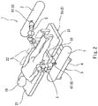
- a first nursing/medical action is an action of changing the body position of the person 10 as shown in Fig. 2 to Fig. 6 .
- changing the body position may be performed during a medical operation or nursing care for the purpose of preventing bedsores.
- a second nursing/medical action is an action of performing a transmission inspection on the person 10 as shown in Fig. 7 .
- a third nursing/medical action is an action of raising the upper half of the body of the person 10 as shown in Fig. 8 to Fig. 10 .
- a fourth nursing/medical action is an action of performing standing-up motion assistance to the person 10 as shown in Fig. 11 to Fig. 13 .
- the robot system 1 includes: the robot 3; and three supporting units 2, on each of which the person 10 is placeable as shown in Fig. 2 to Fig. 13 .
- the three supporting units 2 are: a transformable bed 2A shown in Fig. 2 to Fig. 6 ; a fixed bed 2B shown in Fig. 7 ; and a transformable bed 2C shown in Fig. 8 to Fig. 13 .
- the robot 3 includes: a plurality of multi-jointed arms 5 each having a plurality of degrees of freedom; and at least one base 4 provided with the multi-jointed arms 5.
- each of the multi-jointed arms 5 has at least six degrees of freedom (e.g., seven degrees of freedom).
- the number of bases 4 is one, and the number of multi-jointed arms 5 is two.
- the number of bases 4 may be two or more, and the number of multi-jointed arms 5 may be three or more.
- the base 4 is disposed under the supporting unit 2 such that, during each of the four nursing/medical actions, the entirety of the base 4 is accommodated within the space occupied by the supporting unit 2.
- the relatively large base 4 of the robot 3 is concealed under the supporting unit 2, anyone around the supporting unit 2 can freely come close to the person 10 placed on the supporting unit 2.
- a procedure/treatment e.g., a medical operation or nursing care
- the robot 3 may be configured to perform each of the four nursing/medical actions in accordance with a sound or an operation of a switch.
- the robot 3 is configured such that, during each of the four nursing/medical actions, the two multi-jointed arms 5 can be retracted under the supporting unit 2. Since the two multi-jointed arms 5 have such a retractable configuration, when the robot 3 performs no nursing/medical action, the multi-jointed arms 5 can be retracted under the supporting unit 2, and the robot 3 can be stored under the supporting unit 2.
- a plurality of types (in the present embodiment, two types) of equipment 6 corresponding to the aforementioned nursing/medical actions are each removably mounted to the two multi-jointed arms 5.
- the robot 3 operates these different types of equipment 6 via the multi-jointed arms 5, thereby performing the four nursing/medical actions.
- information obtaining devices such as a camera and a sensor, are attached to the robot 3. Based on information obtained from the information obtaining devices, the multi-jointed arms 5 are controlled by a robot control board 41 (see Fig. 14 ) built in the base 4.
- the two types of equipment 6 are: a pair of hands 61 used for changing the body position and raising the upper half of the body of the person 10; and a pair of transmission inspection devices 62 used for performing the transmission inspection on the person 10.
- the pair of hands 61 is mounted to the two multi-jointed arms 5, such that each hand 61 is mounted to the distal end of a corresponding one of the multi-jointed arms 5.
- the pair of transmission inspection devices 62 is mounted to the two multi-jointed arms 5, such that each transmission inspection device 62 is mounted to the distal end of a corresponding one of the multi-jointed arms 5.
- each of the three supporting units 2 (the transformable bed 2A, the transformable bed 2C, and the fixed bed 2B) is coupled to the base 4. Accordingly, the position of each supporting unit 2 relative to the base 4 of the robot 3 is fixed. This makes it possible to readily perform the positioning of the equipment 6, which is mounted to the multi-jointed arms 5, relative to the person 10 or the supporting unit 2.
- each supporting unit 2 is not necessarily coupled to the base 4, but any or all of the three supporting units 2 may be supported by a support pillar installed upright on a floor on which the robot 3 is placed.
- the base 4 of the robot 3 is movable.
- a moving device 9 as shown in Fig. 14 may be incorporated in the base 4.
- the moving device 9 includes: right and left wheels 92 to be driven; and a front wheel 93, which is a follower wheel.
- the moving device 9 further includes a pair of servomotors 91 configured to drive the right and left wheels 92.
- the robot 3 is moved by controlling the pair of servomotors 91 by the robot control board 41. This configuration makes it possible to freely run the robot 3.
- the base 4 of the robot 3 may be transferred by a transfer mechanism provided on the floor on which the robot 3 is placed.
- the transformable bed 2A which is partly swingable in its width direction, is used as the supporting unit 2.
- the hands 61 are mounted to both the multi-jointed arms 5, respectively.
- the transformable bed 2A is coupled to the base 4.
- the transformable bed 2A is coupled to the base 4 via a first swinging mechanism 23 (described below), which is disposed substantially at the center of the transformable bed 2A.
- the transformable bed 2A is supported by the base 4.
- the transformable bed 2A may be separated from the base 4.
- the transformable bed 2A is divided in its longitudinal direction into a plurality of (in the illustrated example, four) pieces 21.
- Side rails 22 are provided on both ends of each piece 21 in its width direction.
- the four pieces 21 are configured such that the adjoining pieces 21 are rotatable relative to each other about an axis extending in the longitudinal direction of the transformable bed 2A.
- the entire transformable bed 2A is configured to be swingable in its width direction.
- the transformable bed 2A includes: the first swinging mechanism 23 (see Fig. 4 ) configured to swing the entire transformable bed 2A in its width direction; and a second swinging mechanism 24 (see Fig. 5 ) configured to swing each piece 21 in its width direction.
- each cushion 7 may be configured to expand into a predetermined shape when fed with a working fluid, such as water or air, and shrink when the working fluid is discharged therefrom.
- a working fluid such as water or air
- the cushions 7 may be shrunk and retracted under the transformable bed 2A together with the multi-jointed arms 5.
- the robot 3 grabs the cushions 7 with both hands 61, and as shown in Fig. 3 , inserts one of the cushions 7 between the person 10 and the side rails 22. Then, as shown in Fig. 4 , the robot 3 operates the first swinging mechanism 23 with one hand 61 to tilt the entire transformable bed 2A to the inserted cushion 7 side. Thereafter, as shown in Fig. 5 , the robot 3 operates the second swinging mechanism 24 with the same hand 61 to bring one end piece 21 (on the head side of the person 10) back to the horizontal position. Subsequently, as shown in Fig. 6 , the robot 3 inserts the other cushion 7 into a space formed between the one end piece 21 and the person 10 with the other hand 61.
- changing the body position as shown in Fig. 2 to Fig. 6 is merely one example.
- changing the body position can be performed in a different manner. The same is true in the following cases of: performing the transmission inspection on the person 10; raising the upper half of the body of the person 10; and performing the standing-up motion assistance to the person 10, which will be described below.
- the robot 3 may be configured to repeat the action of changing the body position of the person 10 at predetermined intervals.
- the fixed bed 2B is used as the supporting unit 2.
- the transmission inspection devices 62 are mounted to both the multi-jointed arms 5, respectively.
- one of the transmission inspection devices 62 emits an X-ray
- the other transmission inspection device 62 receives the X-ray.
- the robot 3 performs the transmission inspection by moving the pair of transmission inspection devices 62, for example, along a spherical path centered on the head of the person 10.
- the fixed bed 2B is coupled to the base 4.
- the fixed bed 2B is coupled to the base 4 substantially at the center of the fixed bed 2B and supported by the base 4.
- the fixed bed 2B may be separated from the base 4.
- the transformable bed 2C which is transformable between a bed mode and a chair mode, is used as the supporting unit 2.
- the hands 61 are mounted to both the multi-jointed arms 5, respectively.
- the robot 3 operates the transformable bed 2C with the hands 61, thereby raising the upper half of the body of the person 10 via the transformable bed 2C to change the state of the person 10 from a lying-down state into a sitting state.
- Armrests 8, which are used in the standing-up motion assistance (described below), are disposed on both sides of the transformable bed 2C, respectively.
- the transformable bed 2C is coupled to the base 4.
- the transformable bed 2C is coupled to the base 4 via a first raising/lowering mechanism 25 (described below), which is disposed substantially at the center of the transformable bed 2C.
- the transformable bed 2C is supported by the base 4.
- the transformable bed 2C may be separated from the base 4.
- the transformable bed 2C is divided in its longitudinal direction into a plurality of (in the illustrated example, four) pieces 21. Side rails 22 are provided on both ends of each piece 21 in its width direction. The four pieces 21 are configured such that the adjoining pieces 21 are rotatable relative to each other about their respective axes extending in the width direction of the transformable bed 2C.
- the transformable bed 2C includes: the first raising/lowering mechanism 25 (see Fig. 9 ) configured to raise/lower the two pieces 21 on the head side of the person 10; and a second raising/lowering mechanism (not shown) configured to raise/lower the two pieces 21 on the foot side of the person 10.
- the robot 3 When the transformable bed 2C is in the bed mode as shown in Fig. 8 , all of the pieces 21 are horizontal.
- the robot 3 operates the first raising/lowering mechanism 25 with one hand 61 to put the two pieces 21 on the head side in a standing state.
- the robot 3 operates the second raising/lowering mechanism with the other hand 61 to put the two pieces 21 on the foot side in a hanging state.
- the armrests 8 are attached to both the multi-jointed arms 5, respectively.
- the armrest 8 may be attached to only one of the multi-jointed arms 5.
- the robot 3 performs the standing-up motion assistance to support the person 10 with the armrests 8 until the person 10 in the sitting state stands up.
- the robot 3 attaches the armrests 8 to distal-end arm portions of the respective multi-jointed arms 5 with the hands 61. Then, as shown in Fig. 12 , the robot 3 moves both the armrests 8 to the front of the chest of the person 10. Thereafter, the robot 3 opens up the armrests 8 as the person 10 stands up.
- each armrest 8 may be configured by using the cushion 7 described above.
- the interior of the cushion 7, which expands or shrinks due to the working fluid may be segmented into a plurality of cells, and the working fluid may be fed to one of the cells to realize the shape of the armrest 8.
- the armrests 8 may be shrunk and retracted under the transformable bed 2C together with the multi-jointed arms 5.
- the robot system 1 of the present embodiment is capable of using the robot 3 as a platform for a plurality of nursing/medical actions. This makes it possible to perform the plurality of (in the present embodiment, four) nursing/medical actions with the single robot 3. In other words, the robot 3 can be used in common for the four nursing/medical actions.
- the robot 3 may be configured to perform at least two medical actions. Accordingly, the nursing/medical actions to be performed by the robot 3 may be two or three actions among the four nursing/medical actions of the above-described embodiment. As one example, in a case where the robot 3 is configured to only perform the action of changing the body position and the action of raising the upper half of the body, the robot system 1 may only include the hands 61 as the equipment 6. Thus, the robot system 1 may include at least one type of equipment 6.
- the robot system 1 may only include the transformable bed 2C as the supporting unit 2.
- the robot system 1 may include at least one supporting unit 2.
- the supporting unit 2 having a combination of functions, specifically, a combination of the function of the transformable bed 2A of being partly swingable in the width direction and the function of the transformable bed 2C of being transformable between the bed mode and the chair mode, may be used.
- the nursing/medical actions to be performed by the robot 3 are not limited to the nursing/medical actions described in the above embodiment. Examples of other nursing/medical actions performable by the robot 3 include assisting rehabilitation, massaging, and assisting eating.
- Various types of equipment 6 can be mounted to the multi-jointed arms 5 of the robot 3 in accordance with the nursing/medical actions to be performed by the robot 3.
Landscapes
- Health & Medical Sciences (AREA)
- Engineering & Computer Science (AREA)
- Life Sciences & Earth Sciences (AREA)
- General Health & Medical Sciences (AREA)
- Animal Behavior & Ethology (AREA)
- Public Health (AREA)
- Veterinary Medicine (AREA)
- Robotics (AREA)
- Mechanical Engineering (AREA)
- Nursing (AREA)
- Surgery (AREA)
- Biomedical Technology (AREA)
- Nuclear Medicine, Radiotherapy & Molecular Imaging (AREA)
- Heart & Thoracic Surgery (AREA)
- Medical Informatics (AREA)
- Molecular Biology (AREA)
- Oral & Maxillofacial Surgery (AREA)
- Pathology (AREA)
- Invalid Beds And Related Equipment (AREA)
- Manipulator (AREA)
- Accommodation For Nursing Or Treatment Tables (AREA)
Abstract
Description
- The present invention relates to a robot system for performing nursing/medical actions.
- Conventionally, various robots for performing nursing/medical actions on a person have been proposed. For example, Fig. 19 of
Patent Literature 1 discloses a dual-arm nursing robot for lifting a person lying on a bed. - PTL 1:
WO 2009/147832 - Such a conventional nursing/medical care robot is designed such that it is dedicated for a particular nursing/medical action. Therefore, in order to perform a plurality of nursing/medical actions, the same number of robots as the number of the plurality of nursing/medical actions is necessary.
- In view of the above, an object of the present invention is to provide a robot system including a single robot that is capable of performing a plurality of nursing/medical actions.
- In order to solve the above-described problems, a robot system of the present invention includes: at least one supporting unit, on which a person is placeable; a robot including a plurality of multi-jointed arms, each of which has a plurality of degrees of freedom, and at least one base provided with the plurality of multi-jointed arms; and at least one type of equipment mountable to the plurality of multi-jointed arms. The robot performs at least two nursing/medical actions on the person by operating the at least one type of equipment.
- According to the above configuration, the robot can be used as a platform for a plurality of nursing/medical actions. This makes it possible to perform the plurality of nursing/medical actions with the single robot.
- The at least one type of equipment may include a pair of transmission inspection devices that are mounted to two multi-jointed arms, respectively, of the plurality of multi-jointed arms, and the at least two nursing/medical actions may include an action of performing a transmission inspection on the person. According to this configuration, the robot can be used in common for the action of performing the transmission inspection on the person and the other nursing/medical action(s).
- The at least one supporting unit may include a transformable bed partly swingable in its width direction. The at least one type of equipment may include a hand configured to operate the transformable bed. The at least two nursing/medical actions may include an action of changing a body position of the person via the transformable bed to change a position where the person is in contact with the transformable bed. According to this configuration, the robot can be used in common for the action of changing the body position and the other nursing/medical action(s).
- The at least one supporting unit may include a transformable bed transformable between a bed mode and a chair mode. The at least one type of equipment may include a hand configured to operate the transformable bed. The at least two nursing/medical actions may include an action of raising an upper half of a body of the person via the transformable bed to change a state of the person from a lying-down state into a sitting state. According to this configuration, the robot can be used in common for the action of raising the upper half of the body and the other nursing/medical action(s).
- The above robot system may further include an armrest attached to at least one of the plurality of multi-jointed arms. The at least two nursing/medical actions may include an action of performing standing-up motion assistance to the person to support the person with the armrest until the person in the sitting state stands up. According to this configuration, the robot can be used in common for, at least, the action of raising the upper half of the body and the action of performing the standing-up motion assistance.
- For example, the at least one type of equipment may include a plurality of types of equipment, and each type of equipment may be removably mounted to the plurality of multi-jointed arms.
- The at least one supporting unit may be coupled to the at least one base. According to this configuration, the position of the supporting unit relative to the base of the robot is fixed. This makes it possible to readily perform the positioning of the equipment, which is mounted to the multi-jointed arms, relative to the person or the supporting unit.
- The at least one base may be disposed under the supporting unit, such that an entirety of the at least one base is accommodated within a space occupied by the supporting unit. According to this configuration, since the relatively large base of the robot is concealed under the supporting unit, anyone around the supporting unit can freely come close to the person placed on the supporting unit. This allows anyone around the supporting unit to readily perform a procedure/treatment on the person placed on the supporting unit.
- The robot may be configured such that the plurality of multi-jointed arms are retractable under the at least one supporting unit. According to this configuration, when the robot performs no nursing/medical action, the multi-jointed arms can be retracted under the supporting unit, and the robot can be stored under the supporting unit.
- For example, the robot may be configured to perform each of the at least two nursing/medical actions in accordance with a sound or an operation of a switch, and the robot may be configured to repeat the action of changing the body position of the person at predetermined intervals.
- The above robot system may further include a moving device incorporated in the base, the moving device including a pair of servomotors configured to drive right and left wheels. The robot may be moved by controlling the pair of servomotors by a robot control board. This configuration makes it possible to freely run the robot.
- The present invention makes it possible to perform a plurality of nursing/medical actions with a single robot.
-
-
Fig. 1 is a perspective view of a robot in a robot system according to one embodiment of the present invention. -
Fig. 2 is a perspective view of the robot system, the view showing one of the steps in the case of changing a body position. -
Fig. 3 is a perspective view of the robot system, the view showing one of the steps in the case of changing the body position. -
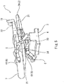
Fig. 4 is a perspective view of the robot system, the view showing one of the steps in the case of changing the body position. -
Fig. 5 is a perspective view of the robot system, the view showing one of the steps in the case of changing the body position. -
Fig. 6 is a perspective view of the robot system, the view showing one of the steps in the case of changing the body position. -
Fig. 7 is a perspective view of the robot system, the view showing one of the steps in the case of performing a transmission inspection. -
Fig. 8 is a perspective view of the robot system, the view showing one of the steps in the case of raising the upper half of the body. -
Fig. 9 is a perspective view of the robot system, the view showing one of the steps in the case of raising the upper half of the body. -
Fig. 10 is a perspective view of the robot system, the view showing one of the steps in the case of raising the upper half of the body. -
Fig. 11 is a perspective view of the robot system, the view showing one of the steps in the case of performing standing-up motion assistance. -
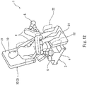
Fig. 12 is a perspective view of the robot system, the view showing one of the steps in the case of performing the standing-up motion assistance. -
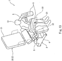
Fig. 13 is a perspective view of the robot system, the view showing one of the steps in the case of performing the standing-up motion assistance. -
Fig. 14 is a bottom view of the robot, the view showing a moving device. -
Figs. 2 to 13 show arobot system 1 according to one embodiment of the present invention.Fig. 1 shows arobot 3 included in therobot system 1. In the present embodiment, therobot 3 performs four nursing/medical actions on aperson 10. Theperson 10 may be different for each of the nursing/medical actions. - A first nursing/medical action is an action of changing the body position of the
person 10 as shown inFig. 2 to Fig. 6 . For example, changing the body position may be performed during a medical operation or nursing care for the purpose of preventing bedsores. A second nursing/medical action is an action of performing a transmission inspection on theperson 10 as shown inFig. 7 . A third nursing/medical action is an action of raising the upper half of the body of theperson 10 as shown inFig. 8 to Fig. 10 . A fourth nursing/medical action is an action of performing standing-up motion assistance to theperson 10 as shown inFig. 11 to Fig. 13 . - The
robot system 1 includes: therobot 3; and three supportingunits 2, on each of which theperson 10 is placeable as shown inFig. 2 to Fig. 13 . The three supportingunits 2 are: atransformable bed 2A shown inFig. 2 to Fig. 6 ; a fixedbed 2B shown inFig. 7 ; and atransformable bed 2C shown inFig. 8 to Fig. 13 . - As shown in
Fig. 1 , therobot 3 includes: a plurality ofmulti-jointed arms 5 each having a plurality of degrees of freedom; and at least onebase 4 provided with themulti-jointed arms 5. Preferably, each of themulti-jointed arms 5 has at least six degrees of freedom (e.g., seven degrees of freedom). In the present embodiment, the number ofbases 4 is one, and the number ofmulti-jointed arms 5 is two. However, as an alternative, the number ofbases 4 may be two or more, and the number ofmulti-jointed arms 5 may be three or more. - In the present embodiment, the
base 4 is disposed under the supportingunit 2 such that, during each of the four nursing/medical actions, the entirety of thebase 4 is accommodated within the space occupied by the supportingunit 2. According to this configuration, since the relativelylarge base 4 of therobot 3 is concealed under the supportingunit 2, anyone around the supportingunit 2 can freely come close to theperson 10 placed on the supportingunit 2. This allows anyone around the supportingunit 2 to readily perform a procedure/treatment (e.g., a medical operation or nursing care) on theperson 10 placed on the supportingunit 2. It should be noted that therobot 3 may be configured to perform each of the four nursing/medical actions in accordance with a sound or an operation of a switch. - Further, in the present embodiment, the
robot 3 is configured such that, during each of the four nursing/medical actions, the twomulti-jointed arms 5 can be retracted under the supportingunit 2. Since the twomulti-jointed arms 5 have such a retractable configuration, when therobot 3 performs no nursing/medical action, themulti-jointed arms 5 can be retracted under the supportingunit 2, and therobot 3 can be stored under the supportingunit 2. - A plurality of types (in the present embodiment, two types) of
equipment 6 corresponding to the aforementioned nursing/medical actions are each removably mounted to the twomulti-jointed arms 5. Therobot 3 operates these different types ofequipment 6 via themulti-jointed arms 5, thereby performing the four nursing/medical actions. Although not illustrated, information obtaining devices, such as a camera and a sensor, are attached to therobot 3. Based on information obtained from the information obtaining devices, themulti-jointed arms 5 are controlled by a robot control board 41 (seeFig. 14 ) built in thebase 4. - The two types of
equipment 6 are: a pair ofhands 61 used for changing the body position and raising the upper half of the body of theperson 10; and a pair oftransmission inspection devices 62 used for performing the transmission inspection on theperson 10. The pair ofhands 61 is mounted to the twomulti-jointed arms 5, such that eachhand 61 is mounted to the distal end of a corresponding one of themulti-jointed arms 5. Alternatively, Instead of thehands 61, the pair oftransmission inspection devices 62 is mounted to the twomulti-jointed arms 5, such that eachtransmission inspection device 62 is mounted to the distal end of a corresponding one of themulti-jointed arms 5. - In the present embodiment, each of the three supporting units 2 (the
transformable bed 2A, thetransformable bed 2C, and the fixedbed 2B) is coupled to thebase 4. Accordingly, the position of each supportingunit 2 relative to thebase 4 of therobot 3 is fixed. This makes it possible to readily perform the positioning of theequipment 6, which is mounted to themulti-jointed arms 5, relative to theperson 10 or the supportingunit 2. It should be noted that each supportingunit 2 is not necessarily coupled to thebase 4, but any or all of the three supportingunits 2 may be supported by a support pillar installed upright on a floor on which therobot 3 is placed. - Desirably, the
base 4 of therobot 3 is movable. For example, a movingdevice 9 as shown inFig. 14 may be incorporated in thebase 4. The movingdevice 9 includes: right and leftwheels 92 to be driven; and afront wheel 93, which is a follower wheel. The movingdevice 9 further includes a pair ofservomotors 91 configured to drive the right and leftwheels 92. Therobot 3 is moved by controlling the pair ofservomotors 91 by therobot control board 41. This configuration makes it possible to freely run therobot 3. However, as an alternative, thebase 4 of therobot 3 may be transferred by a transfer mechanism provided on the floor on which therobot 3 is placed. - Hereinafter, the aforementioned nursing/medical actions (changing the body position, performing the transmission inspection, raising the upper half of the body, and performing the standing-up motion assistance) are described in detail.
- As shown in
Fig. 2 to Fig. 6 , in the case of changing the body position, thetransformable bed 2A, which is partly swingable in its width direction, is used as the supportingunit 2. Also, in the case of changing the body position, thehands 61 are mounted to both themulti-jointed arms 5, respectively. By operating thetransformable bed 2A with thehands 61, therobot 3 changes the body position of theperson 10 via thetransformable bed 2A to change the positions where theperson 10 is in contact with thetransformable bed 2A. - As mentioned above, the
transformable bed 2A is coupled to thebase 4. In the present embodiment, thetransformable bed 2A is coupled to thebase 4 via a first swinging mechanism 23 (described below), which is disposed substantially at the center of thetransformable bed 2A. Thetransformable bed 2A is supported by thebase 4. However, as previously mentioned, thetransformable bed 2A may be separated from thebase 4. - The
transformable bed 2A is divided in its longitudinal direction into a plurality of (in the illustrated example, four)pieces 21. Side rails 22 are provided on both ends of eachpiece 21 in its width direction. The fourpieces 21 are configured such that the adjoiningpieces 21 are rotatable relative to each other about an axis extending in the longitudinal direction of thetransformable bed 2A. - Further, in the present embodiment, the entire
transformable bed 2A is configured to be swingable in its width direction. Thetransformable bed 2A includes: the first swinging mechanism 23 (seeFig. 4 ) configured to swing the entiretransformable bed 2A in its width direction; and a second swinging mechanism 24 (seeFig. 5 ) configured to swing eachpiece 21 in its width direction. - Still further, in the present embodiment, in the case of changing the body position, a pair of log-shaped
cushions 7 for theperson 10 is used. For example, eachcushion 7 may be configured to expand into a predetermined shape when fed with a working fluid, such as water or air, and shrink when the working fluid is discharged therefrom. When therobot 3 performs no nursing/medical action, thecushions 7 may be shrunk and retracted under thetransformable bed 2A together with themulti-jointed arms 5. - First, the
robot 3 grabs thecushions 7 with bothhands 61, and as shown inFig. 3 , inserts one of thecushions 7 between theperson 10 and the side rails 22. Then, as shown inFig. 4 , therobot 3 operates thefirst swinging mechanism 23 with onehand 61 to tilt the entiretransformable bed 2A to the insertedcushion 7 side. Thereafter, as shown inFig. 5 , therobot 3 operates thesecond swinging mechanism 24 with thesame hand 61 to bring one end piece 21 (on the head side of the person 10) back to the horizontal position. Subsequently, as shown inFig. 6 , therobot 3 inserts theother cushion 7 into a space formed between the oneend piece 21 and theperson 10 with theother hand 61. - It should be noted that changing the body position as shown in
Fig. 2 to Fig. 6 is merely one example. Of course, changing the body position can be performed in a different manner. The same is true in the following cases of: performing the transmission inspection on theperson 10; raising the upper half of the body of theperson 10; and performing the standing-up motion assistance to theperson 10, which will be described below. Therobot 3 may be configured to repeat the action of changing the body position of theperson 10 at predetermined intervals. - As shown in
Fig. 7 , in the case of performing the transmission inspection, the fixedbed 2B is used as the supportingunit 2. Also, in the case of performing the transmission inspection, thetransmission inspection devices 62 are mounted to both themulti-jointed arms 5, respectively. For example, one of thetransmission inspection devices 62 emits an X-ray, and the othertransmission inspection device 62 receives the X-ray. Therobot 3 performs the transmission inspection by moving the pair oftransmission inspection devices 62, for example, along a spherical path centered on the head of theperson 10. - As mentioned above, the fixed
bed 2B is coupled to thebase 4. In the present embodiment, the fixedbed 2B is coupled to thebase 4 substantially at the center of the fixedbed 2B and supported by thebase 4. However, as previously mentioned, the fixedbed 2B may be separated from thebase 4. - As shown in
Fig. 8 to Fig. 10 , in the case of raising the upper half of the body, thetransformable bed 2C, which is transformable between a bed mode and a chair mode, is used as the supportingunit 2. Also, in the case of changing the body position, thehands 61 are mounted to both themulti-jointed arms 5, respectively. Therobot 3 operates thetransformable bed 2C with thehands 61, thereby raising the upper half of the body of theperson 10 via thetransformable bed 2C to change the state of theperson 10 from a lying-down state into a sitting state.Armrests 8, which are used in the standing-up motion assistance (described below), are disposed on both sides of thetransformable bed 2C, respectively. - As mentioned above, the
transformable bed 2C is coupled to thebase 4. In the present embodiment, thetransformable bed 2C is coupled to thebase 4 via a first raising/lowering mechanism 25 (described below), which is disposed substantially at the center of thetransformable bed 2C. Thetransformable bed 2C is supported by thebase 4. However, as previously mentioned, thetransformable bed 2C may be separated from thebase 4. - The
transformable bed 2C is divided in its longitudinal direction into a plurality of (in the illustrated example, four)pieces 21. Side rails 22 are provided on both ends of eachpiece 21 in its width direction. The fourpieces 21 are configured such that the adjoiningpieces 21 are rotatable relative to each other about their respective axes extending in the width direction of thetransformable bed 2C. Thetransformable bed 2C includes: the first raising/lowering mechanism 25 (seeFig. 9 ) configured to raise/lower the twopieces 21 on the head side of theperson 10; and a second raising/lowering mechanism (not shown) configured to raise/lower the twopieces 21 on the foot side of theperson 10. - When the
transformable bed 2C is in the bed mode as shown inFig. 8 , all of thepieces 21 are horizontal. First, as shown inFig. 9 , therobot 3 operates the first raising/loweringmechanism 25 with onehand 61 to put the twopieces 21 on the head side in a standing state. Then, as shown inFig. 10 , therobot 3 operates the second raising/lowering mechanism with theother hand 61 to put the twopieces 21 on the foot side in a hanging state. - As shown in
Fig. 11 to Fig. 13 , in the case of performing the standing-up motion assistance, thearmrests 8 are attached to both themulti-jointed arms 5, respectively. However, as an alternative, thearmrest 8 may be attached to only one of themulti-jointed arms 5. Therobot 3 performs the standing-up motion assistance to support theperson 10 with thearmrests 8 until theperson 10 in the sitting state stands up. - Specifically, first, as shown in
Fig. 11 , therobot 3 attaches thearmrests 8 to distal-end arm portions of the respectivemulti-jointed arms 5 with thehands 61. Then, as shown inFig. 12 , therobot 3 moves both thearmrests 8 to the front of the chest of theperson 10. Thereafter, therobot 3 opens up thearmrests 8 as theperson 10 stands up. - For example, each
armrest 8 may be configured by using thecushion 7 described above. To be more specific, the interior of thecushion 7, which expands or shrinks due to the working fluid, may be segmented into a plurality of cells, and the working fluid may be fed to one of the cells to realize the shape of thearmrest 8. When therobot 3 performs no nursing/medical action, thearmrests 8 may be shrunk and retracted under thetransformable bed 2C together with themulti-jointed arms 5. - As described above, the
robot system 1 of the present embodiment is capable of using therobot 3 as a platform for a plurality of nursing/medical actions. This makes it possible to perform the plurality of (in the present embodiment, four) nursing/medical actions with thesingle robot 3. In other words, therobot 3 can be used in common for the four nursing/medical actions. - The present invention is not limited to the above-described embodiment. Various modifications can be made without departing from the spirit of the present invention.
- For example, the
robot 3 may be configured to perform at least two medical actions. Accordingly, the nursing/medical actions to be performed by therobot 3 may be two or three actions among the four nursing/medical actions of the above-described embodiment. As one example, in a case where therobot 3 is configured to only perform the action of changing the body position and the action of raising the upper half of the body, therobot system 1 may only include thehands 61 as theequipment 6. Thus, therobot system 1 may include at least one type ofequipment 6. - As another example, in a case where the
robot 3 is configured to only perform the action of raising the upper half of the body and the action of performing the standing-up motion assistance, therobot system 1 may only include thetransformable bed 2C as the supportingunit 2. Thus, therobot system 1 may include at least one supportingunit 2. - Alternatively, the supporting
unit 2 having a combination of functions, specifically, a combination of the function of thetransformable bed 2A of being partly swingable in the width direction and the function of thetransformable bed 2C of being transformable between the bed mode and the chair mode, may be used. - The nursing/medical actions to be performed by the
robot 3 are not limited to the nursing/medical actions described in the above embodiment. Examples of other nursing/medical actions performable by therobot 3 include assisting rehabilitation, massaging, and assisting eating. Various types ofequipment 6 can be mounted to themulti-jointed arms 5 of therobot 3 in accordance with the nursing/medical actions to be performed by therobot 3. -
- 1
- robot system
- 10
- person
- 2
- supporting unit
- 2A, 2C
- transformable bed
- 3
- robot
- 4
- base
- 41
- robot control board
- 5
- multi-jointed arm
- 6
- equipment
- 61
- hand
- 62
- transmission inspection device
- 8
- armrest
- 9
- moving device
- 91
- servomotor
- 92, 93
- wheel
Claims (12)
- A robot system comprising:at least one supporting unit, on which a person is placeable;a robot including a plurality of multi-jointed arms, each of which has a plurality of degrees of freedom, and at least one base provided with the plurality of multi-jointed arms; andat least one type of equipment mountable to the plurality of multi-jointed arms, whereinthe robot performs at least two nursing/medical actions on the person by operating the at least one type of equipment.
- The robot system according to claim 1, wherein
the at least one type of equipment includes a pair of transmission inspection devices that are mounted to two multi-jointed arms, respectively, of the plurality of multi-jointed arms, and
the at least two nursing/medical actions include an action of performing a transmission inspection on the person. - The robot system according to claim 1 or 2, wherein
the at least one supporting unit includes a transformable bed partly swingable in its width direction,
the at least one type of equipment includes a hand configured to operate the transformable bed, and
the at least two nursing/medical actions include an action of changing a body position of the person via the transformable bed to change a position where the person is in contact with the transformable bed. - The robot system according to any one of claims 1 to 3, wherein
the at least one supporting unit includes a transformable bed transformable between a bed mode and a chair mode,
the at least one type of equipment includes a hand configured to operate the transformable bed, and
the at least two nursing/medical actions include an action of raising an upper half of a body of the person via the transformable bed to change a state of the person from a lying-down state into a sitting state. - The robot system according to claim 4, further comprising an armrest attached to at least one of the plurality of multi-jointed arms, wherein
the at least two nursing/medical actions include an action of performing standing-up motion assistance to the person to support the person with the armrest until the person in the sitting state stands up. - The robot system according to any one of claims 1 to 5, wherein
the at least one type of equipment includes a plurality of types of equipment, and
each type of equipment is removably mounted to the plurality of multi-jointed arms. - The robot system according to any one of claims 1 to 6, wherein
the at least one supporting unit is coupled to the at least one base. - The robot system according to any one of claims 1 to 7, wherein
the at least one base is disposed under the supporting unit, such that an entirety of the at least one base is accommodated within a space occupied by the supporting unit. - The robot system according to any one of claims 1 to 8, wherein
the robot is configured such that the plurality of multi-jointed arms are retractable under the at least one supporting unit. - The robot system according to any one of claims 1 to 9, wherein
the robot is configured to perform each of the at least two nursing/medical actions in accordance with a sound or an operation of a switch. - The robot system according to claim 3, wherein
the robot is configured to repeat the action of changing the body position of the person at predetermined intervals. - The robot system according to any one of claims 1 to 11, further comprising a moving device incorporated in the base, the moving device including a pair of servomotors configured to drive right and left wheels, wherein
the robot is moved by controlling the pair of servomotors by a robot control board.
Applications Claiming Priority (1)
| Application Number | Priority Date | Filing Date | Title |
|---|---|---|---|
| PCT/JP2015/003251 WO2017002142A1 (en) | 2015-06-29 | 2015-06-29 | Robot system |
Publications (3)
| Publication Number | Publication Date |
|---|---|
| EP3315108A1 true EP3315108A1 (en) | 2018-05-02 |
| EP3315108A4 EP3315108A4 (en) | 2019-01-16 |
| EP3315108B1 EP3315108B1 (en) | 2020-01-29 |
Family
ID=57608006
Family Applications (1)
| Application Number | Title | Priority Date | Filing Date |
|---|---|---|---|
| EP15897070.7A Active EP3315108B1 (en) | 2015-06-29 | 2015-06-29 | Robot system |
Country Status (6)
| Country | Link |
|---|---|
| US (1) | US10940067B2 (en) |
| EP (1) | EP3315108B1 (en) |
| JP (1) | JP6799534B2 (en) |
| KR (1) | KR102055313B1 (en) |
| CN (1) | CN107624063B (en) |
| WO (1) | WO2017002142A1 (en) |
Families Citing this family (13)
| Publication number | Priority date | Publication date | Assignee | Title |
|---|---|---|---|---|
| CN107693289A (en) * | 2017-07-28 | 2018-02-16 | 严驿 | Operation auxiliary support frame |
| US11553973B2 (en) * | 2019-07-29 | 2023-01-17 | Verb Surgical Inc. | Robotic arm having an extendable prismatic link |
| CA3151938A1 (en) | 2019-08-23 | 2021-03-04 | Agex Therapeutics, Inc. | Differentially-methylated regions of the genome useful as markers of embryo-adult transitions |
| CN113350087B (en) * | 2020-03-16 | 2022-05-24 | 金华市中心医院 | Suspension frame simulating hand-lifting burn patient |
| KR20210126255A (en) | 2020-04-10 | 2021-10-20 | 서홍태 | Mobile massage device and method for controlling thereof |
| CN112643646B (en) * | 2020-09-02 | 2022-01-28 | 王卫华 | Omnidirectional movement formula both arms assembly robot based on initiative universal wheel |
| WO2022079875A1 (en) | 2020-10-15 | 2022-04-21 | リバーフィールド株式会社 | Work assistance robot |
| CN112975997B (en) * | 2021-02-05 | 2022-03-15 | 西安秦玄汉信息科技有限公司 | Multi-mechanical-arm nursing system, nursing robot and nursing platform |
| KR102647739B1 (en) * | 2021-12-06 | 2024-03-14 | (주)씨비에이치 | Upper Plate of Operating Table comprising Position-Variable Arm Board |
| CN115957007A (en) * | 2022-09-20 | 2023-04-14 | 核动医疗机器人(深圳)有限公司 | Surgical Robotic System |
| CN117037581A (en) * | 2023-08-17 | 2023-11-10 | 苏州市独墅湖医院(苏州大学附属独墅湖医院) | Limb nursing presentation device is used in clinical care teaching |
| JP7744552B1 (en) * | 2023-12-21 | 2025-09-25 | 株式会社イトーキ | Care equipment |
| WO2026085446A2 (en) * | 2024-10-18 | 2026-04-23 | Massachusetts Institute Of Technology | Robotic systems and methods for assisting a user from standing to sitting |
Family Cites Families (20)
| Publication number | Priority date | Publication date | Assignee | Title |
|---|---|---|---|---|
| US6584628B1 (en) * | 1995-08-04 | 2003-07-01 | Hill-Rom Services, Inc. | Hospital bed having a rotational therapy device |
| CN2397916Y (en) * | 1999-11-01 | 2000-09-27 | 邢耀光 | Mattress for supporting patient turn-over |
| AU2744701A (en) * | 1999-12-29 | 2001-07-09 | Hill-Rom Services, Inc. | Hospital bed |
| JP2002153521A (en) * | 2000-11-20 | 2002-05-28 | Iwakura Corporation:Kk | Mobile nursing machine |
| US8160205B2 (en) * | 2004-04-06 | 2012-04-17 | Accuray Incorporated | Robotic arm for patient positioning assembly |
| US7665166B2 (en) * | 2006-06-15 | 2010-02-23 | Martin Manufacturing Company, Llc | Patient examination system |
| US8909370B2 (en) * | 2007-05-08 | 2014-12-09 | Massachusetts Institute Of Technology | Interactive systems employing robotic companions |
| US8792964B2 (en) | 2008-03-12 | 2014-07-29 | Siemens Aktiengesellschaft | Method and apparatus for conducting an interventional procedure involving heart valves using a robot-based X-ray device |
| JP4634541B2 (en) | 2008-06-06 | 2011-02-16 | パナソニック株式会社 | Robot, robot control device, control method, and control program |
| US8126114B2 (en) * | 2008-09-12 | 2012-02-28 | Accuray Incorporated | Seven or more degrees of freedom robotic manipulator having at least one redundant joint |
| JP5481110B2 (en) * | 2009-07-02 | 2014-04-23 | 株式会社吉田製作所 | Dental treatment chair |
| US8442738B2 (en) * | 2009-10-12 | 2013-05-14 | Stryker Corporation | Speed control for patient handling device |
| US8499379B2 (en) * | 2010-07-30 | 2013-08-06 | Toyota Motor Engineering & Manufacturing North America, Inc. | Robotic posture transfer assist devices and methods |
| JP5759217B2 (en) * | 2011-03-25 | 2015-08-05 | 富士機械製造株式会社 | Stand-up motion assist robot |
| US20130085510A1 (en) * | 2011-09-30 | 2013-04-04 | Ethicon Endo-Surgery, Inc. | Robot-mounted surgical tables |
| FR2983059B1 (en) | 2011-11-30 | 2014-11-28 | Medtech | ROBOTIC-ASSISTED METHOD OF POSITIONING A SURGICAL INSTRUMENT IN RELATION TO THE BODY OF A PATIENT AND DEVICE FOR CARRYING OUT SAID METHOD |
| US9254234B2 (en) * | 2012-04-11 | 2016-02-09 | University of Pittsburgh—of the Commonwealth System of Higher Education | Robotic strong arm |
| US10292887B2 (en) * | 2012-12-31 | 2019-05-21 | Mako Surgical Corp. | Motorized joint positioner |
| JP6307835B2 (en) | 2013-10-28 | 2018-04-11 | セイコーエプソン株式会社 | Robot, robot controller and robot system |
| US9814640B1 (en) * | 2014-10-31 | 2017-11-14 | Space Technology Research LLC | Robotic arm bed assist |
-
2015
- 2015-06-29 KR KR1020187001647A patent/KR102055313B1/en active Active
- 2015-06-29 JP JP2017525684A patent/JP6799534B2/en active Active
- 2015-06-29 CN CN201580080711.7A patent/CN107624063B/en active Active
- 2015-06-29 US US15/741,054 patent/US10940067B2/en active Active
- 2015-06-29 WO PCT/JP2015/003251 patent/WO2017002142A1/en not_active Ceased
- 2015-06-29 EP EP15897070.7A patent/EP3315108B1/en active Active
Also Published As
| Publication number | Publication date |
|---|---|
| KR20180019684A (en) | 2018-02-26 |
| WO2017002142A1 (en) | 2017-01-05 |
| JPWO2017002142A1 (en) | 2018-04-12 |
| JP6799534B2 (en) | 2020-12-16 |
| CN107624063B (en) | 2020-11-20 |
| US20180185219A1 (en) | 2018-07-05 |
| EP3315108B1 (en) | 2020-01-29 |
| US10940067B2 (en) | 2021-03-09 |
| CN107624063A (en) | 2018-01-23 |
| EP3315108A4 (en) | 2019-01-16 |
| KR102055313B1 (en) | 2019-12-12 |
Similar Documents
| Publication | Publication Date | Title |
|---|---|---|
| US10940067B2 (en) | Robot system | |
| US11116683B2 (en) | Lift assembly for patient support apparatus | |
| CN203988858U (en) | A kind of gynecological examining table | |
| JP6711959B2 (en) | Low mobility human stretcher | |
| KR102265885B1 (en) | Electric wheelchair with multiple mode type changes | |
| US9814640B1 (en) | Robotic arm bed assist | |
| ES2913124T3 (en) | Robotic device for verticalization and assistance in the movement of subjects with severe motor disabilities | |
| US20160354267A1 (en) | Transfer device | |
| JP2011098005A (en) | Stretcher for care | |
| US20110035876A1 (en) | Human body supporting apparatus | |
| US11701781B2 (en) | Multi-arm robot for realizing conversion between sitting and lying posture of patients and carrying patients to different positions | |
| KR102076161B1 (en) | The bed for patient | |
| JP2004135855A (en) | Care support device | |
| CN221180646U (en) | An intelligent hanging chair in operating room | |
| ES2947525T3 (en) | Assisted lifting devices for rolling stretchers | |
| CN209864378U (en) | Nursing sickbed | |
| US20160000624A1 (en) | Apparatus for preventing bedsores | |
| JP2021019963A (en) | Care bed | |
| JP5255721B2 (en) | Examination table | |
| JP2017217188A (en) | Mobile carriage for nursing care | |
| KR20210043838A (en) | Transfer device for lying patient | |
| JP2015157057A (en) | Care robot with assist arms | |
| CN109846638B (en) | A nursing bed with turning function | |
| KR102233108B1 (en) | Body rising apparatus and body moving system having the same | |
| WO2014128558A1 (en) | A multifunctional bed |
Legal Events
| Date | Code | Title | Description |
|---|---|---|---|
| STAA | Information on the status of an ep patent application or granted ep patent |
Free format text: STATUS: THE INTERNATIONAL PUBLICATION HAS BEEN MADE |
|
| PUAI | Public reference made under article 153(3) epc to a published international application that has entered the european phase |
Free format text: ORIGINAL CODE: 0009012 |
|
| STAA | Information on the status of an ep patent application or granted ep patent |
Free format text: STATUS: REQUEST FOR EXAMINATION WAS MADE |
|
| 17P | Request for examination filed |
Effective date: 20180129 |
|
| AK | Designated contracting states |
Kind code of ref document: A1 Designated state(s): AL AT BE BG CH CY CZ DE DK EE ES FI FR GB GR HR HU IE IS IT LI LT LU LV MC MK MT NL NO PL PT RO RS SE SI SK SM TR |
|
| AX | Request for extension of the european patent |
Extension state: BA ME |
|
| DAV | Request for validation of the european patent (deleted) | ||
| DAX | Request for extension of the european patent (deleted) | ||
| A4 | Supplementary search report drawn up and despatched |
Effective date: 20181214 |
|
| RIC1 | Information provided on ipc code assigned before grant |
Ipc: B25J 9/06 20060101ALI20181210BHEP Ipc: A61G 13/00 20060101AFI20181210BHEP |
|
| GRAP | Despatch of communication of intention to grant a patent |
Free format text: ORIGINAL CODE: EPIDOSNIGR1 |
|
| STAA | Information on the status of an ep patent application or granted ep patent |
Free format text: STATUS: GRANT OF PATENT IS INTENDED |
|
| INTG | Intention to grant announced |
Effective date: 20190802 |
|
| GRAS | Grant fee paid |
Free format text: ORIGINAL CODE: EPIDOSNIGR3 |
|
| GRAA | (expected) grant |
Free format text: ORIGINAL CODE: 0009210 |
|
| STAA | Information on the status of an ep patent application or granted ep patent |
Free format text: STATUS: THE PATENT HAS BEEN GRANTED |
|
| AK | Designated contracting states |
Kind code of ref document: B1 Designated state(s): AL AT BE BG CH CY CZ DE DK EE ES FI FR GB GR HR HU IE IS IT LI LT LU LV MC MK MT NL NO PL PT RO RS SE SI SK SM TR |
|
| REG | Reference to a national code |
Ref country code: GB Ref legal event code: FG4D |
|
| REG | Reference to a national code |
Ref country code: CH Ref legal event code: EP |
|
| REG | Reference to a national code |
Ref country code: AT Ref legal event code: REF Ref document number: 1227986 Country of ref document: AT Kind code of ref document: T Effective date: 20200215 |
|
| REG | Reference to a national code |
Ref country code: IE Ref legal event code: FG4D |
|
| REG | Reference to a national code |
Ref country code: DE Ref legal event code: R096 Ref document number: 602015046315 Country of ref document: DE |
|
| REG | Reference to a national code |
Ref country code: NL Ref legal event code: MP Effective date: 20200129 |
|
| PG25 | Lapsed in a contracting state [announced via postgrant information from national office to epo] |
Ref country code: FI Free format text: LAPSE BECAUSE OF FAILURE TO SUBMIT A TRANSLATION OF THE DESCRIPTION OR TO PAY THE FEE WITHIN THE PRESCRIBED TIME-LIMIT Effective date: 20200129 Ref country code: NO Free format text: LAPSE BECAUSE OF FAILURE TO SUBMIT A TRANSLATION OF THE DESCRIPTION OR TO PAY THE FEE WITHIN THE PRESCRIBED TIME-LIMIT Effective date: 20200429 Ref country code: PT Free format text: LAPSE BECAUSE OF FAILURE TO SUBMIT A TRANSLATION OF THE DESCRIPTION OR TO PAY THE FEE WITHIN THE PRESCRIBED TIME-LIMIT Effective date: 20200621 Ref country code: RS Free format text: LAPSE BECAUSE OF FAILURE TO SUBMIT A TRANSLATION OF THE DESCRIPTION OR TO PAY THE FEE WITHIN THE PRESCRIBED TIME-LIMIT Effective date: 20200129 |
|
| REG | Reference to a national code |
Ref country code: LT Ref legal event code: MG4D |
|
| PG25 | Lapsed in a contracting state [announced via postgrant information from national office to epo] |
Ref country code: BG Free format text: LAPSE BECAUSE OF FAILURE TO SUBMIT A TRANSLATION OF THE DESCRIPTION OR TO PAY THE FEE WITHIN THE PRESCRIBED TIME-LIMIT Effective date: 20200429 Ref country code: IS Free format text: LAPSE BECAUSE OF FAILURE TO SUBMIT A TRANSLATION OF THE DESCRIPTION OR TO PAY THE FEE WITHIN THE PRESCRIBED TIME-LIMIT Effective date: 20200529 Ref country code: HR Free format text: LAPSE BECAUSE OF FAILURE TO SUBMIT A TRANSLATION OF THE DESCRIPTION OR TO PAY THE FEE WITHIN THE PRESCRIBED TIME-LIMIT Effective date: 20200129 Ref country code: SE Free format text: LAPSE BECAUSE OF FAILURE TO SUBMIT A TRANSLATION OF THE DESCRIPTION OR TO PAY THE FEE WITHIN THE PRESCRIBED TIME-LIMIT Effective date: 20200129 Ref country code: LV Free format text: LAPSE BECAUSE OF FAILURE TO SUBMIT A TRANSLATION OF THE DESCRIPTION OR TO PAY THE FEE WITHIN THE PRESCRIBED TIME-LIMIT Effective date: 20200129 Ref country code: GR Free format text: LAPSE BECAUSE OF FAILURE TO SUBMIT A TRANSLATION OF THE DESCRIPTION OR TO PAY THE FEE WITHIN THE PRESCRIBED TIME-LIMIT Effective date: 20200430 |
|
| PG25 | Lapsed in a contracting state [announced via postgrant information from national office to epo] |
Ref country code: NL Free format text: LAPSE BECAUSE OF FAILURE TO SUBMIT A TRANSLATION OF THE DESCRIPTION OR TO PAY THE FEE WITHIN THE PRESCRIBED TIME-LIMIT Effective date: 20200129 |
|
| PG25 | Lapsed in a contracting state [announced via postgrant information from national office to epo] |
Ref country code: ES Free format text: LAPSE BECAUSE OF FAILURE TO SUBMIT A TRANSLATION OF THE DESCRIPTION OR TO PAY THE FEE WITHIN THE PRESCRIBED TIME-LIMIT Effective date: 20200129 Ref country code: RO Free format text: LAPSE BECAUSE OF FAILURE TO SUBMIT A TRANSLATION OF THE DESCRIPTION OR TO PAY THE FEE WITHIN THE PRESCRIBED TIME-LIMIT Effective date: 20200129 Ref country code: LT Free format text: LAPSE BECAUSE OF FAILURE TO SUBMIT A TRANSLATION OF THE DESCRIPTION OR TO PAY THE FEE WITHIN THE PRESCRIBED TIME-LIMIT Effective date: 20200129 Ref country code: CZ Free format text: LAPSE BECAUSE OF FAILURE TO SUBMIT A TRANSLATION OF THE DESCRIPTION OR TO PAY THE FEE WITHIN THE PRESCRIBED TIME-LIMIT Effective date: 20200129 Ref country code: EE Free format text: LAPSE BECAUSE OF FAILURE TO SUBMIT A TRANSLATION OF THE DESCRIPTION OR TO PAY THE FEE WITHIN THE PRESCRIBED TIME-LIMIT Effective date: 20200129 Ref country code: SM Free format text: LAPSE BECAUSE OF FAILURE TO SUBMIT A TRANSLATION OF THE DESCRIPTION OR TO PAY THE FEE WITHIN THE PRESCRIBED TIME-LIMIT Effective date: 20200129 Ref country code: DK Free format text: LAPSE BECAUSE OF FAILURE TO SUBMIT A TRANSLATION OF THE DESCRIPTION OR TO PAY THE FEE WITHIN THE PRESCRIBED TIME-LIMIT Effective date: 20200129 Ref country code: SK Free format text: LAPSE BECAUSE OF FAILURE TO SUBMIT A TRANSLATION OF THE DESCRIPTION OR TO PAY THE FEE WITHIN THE PRESCRIBED TIME-LIMIT Effective date: 20200129 |
|
| REG | Reference to a national code |
Ref country code: DE Ref legal event code: R097 Ref document number: 602015046315 Country of ref document: DE |
|
| REG | Reference to a national code |
Ref country code: AT Ref legal event code: MK05 Ref document number: 1227986 Country of ref document: AT Kind code of ref document: T Effective date: 20200129 |
|
| PLBE | No opposition filed within time limit |
Free format text: ORIGINAL CODE: 0009261 |
|
| STAA | Information on the status of an ep patent application or granted ep patent |
Free format text: STATUS: NO OPPOSITION FILED WITHIN TIME LIMIT |
|
| 26N | No opposition filed |
Effective date: 20201030 |
|
| PG25 | Lapsed in a contracting state [announced via postgrant information from national office to epo] |
Ref country code: MC Free format text: LAPSE BECAUSE OF FAILURE TO SUBMIT A TRANSLATION OF THE DESCRIPTION OR TO PAY THE FEE WITHIN THE PRESCRIBED TIME-LIMIT Effective date: 20200129 Ref country code: AT Free format text: LAPSE BECAUSE OF FAILURE TO SUBMIT A TRANSLATION OF THE DESCRIPTION OR TO PAY THE FEE WITHIN THE PRESCRIBED TIME-LIMIT Effective date: 20200129 |
|
| REG | Reference to a national code |
Ref country code: CH Ref legal event code: PL |
|
| PG25 | Lapsed in a contracting state [announced via postgrant information from national office to epo] |
Ref country code: SI Free format text: LAPSE BECAUSE OF FAILURE TO SUBMIT A TRANSLATION OF THE DESCRIPTION OR TO PAY THE FEE WITHIN THE PRESCRIBED TIME-LIMIT Effective date: 20200129 Ref country code: PL Free format text: LAPSE BECAUSE OF FAILURE TO SUBMIT A TRANSLATION OF THE DESCRIPTION OR TO PAY THE FEE WITHIN THE PRESCRIBED TIME-LIMIT Effective date: 20200129 |
|
| GBPC | Gb: european patent ceased through non-payment of renewal fee |
Effective date: 20200629 |
|
| PG25 | Lapsed in a contracting state [announced via postgrant information from national office to epo] |
Ref country code: LU Free format text: LAPSE BECAUSE OF NON-PAYMENT OF DUE FEES Effective date: 20200629 |
|
| REG | Reference to a national code |
Ref country code: BE Ref legal event code: MM Effective date: 20200630 |
|
| PG25 | Lapsed in a contracting state [announced via postgrant information from national office to epo] |
Ref country code: LI Free format text: LAPSE BECAUSE OF NON-PAYMENT OF DUE FEES Effective date: 20200630 Ref country code: CH Free format text: LAPSE BECAUSE OF NON-PAYMENT OF DUE FEES Effective date: 20200630 Ref country code: IE Free format text: LAPSE BECAUSE OF NON-PAYMENT OF DUE FEES Effective date: 20200629 Ref country code: GB Free format text: LAPSE BECAUSE OF NON-PAYMENT OF DUE FEES Effective date: 20200629 |
|
| PG25 | Lapsed in a contracting state [announced via postgrant information from national office to epo] |
Ref country code: BE Free format text: LAPSE BECAUSE OF NON-PAYMENT OF DUE FEES Effective date: 20200630 |
|
| PG25 | Lapsed in a contracting state [announced via postgrant information from national office to epo] |
Ref country code: TR Free format text: LAPSE BECAUSE OF FAILURE TO SUBMIT A TRANSLATION OF THE DESCRIPTION OR TO PAY THE FEE WITHIN THE PRESCRIBED TIME-LIMIT Effective date: 20200129 Ref country code: MT Free format text: LAPSE BECAUSE OF FAILURE TO SUBMIT A TRANSLATION OF THE DESCRIPTION OR TO PAY THE FEE WITHIN THE PRESCRIBED TIME-LIMIT Effective date: 20200129 Ref country code: CY Free format text: LAPSE BECAUSE OF FAILURE TO SUBMIT A TRANSLATION OF THE DESCRIPTION OR TO PAY THE FEE WITHIN THE PRESCRIBED TIME-LIMIT Effective date: 20200129 |
|
| PG25 | Lapsed in a contracting state [announced via postgrant information from national office to epo] |
Ref country code: MK Free format text: LAPSE BECAUSE OF FAILURE TO SUBMIT A TRANSLATION OF THE DESCRIPTION OR TO PAY THE FEE WITHIN THE PRESCRIBED TIME-LIMIT Effective date: 20200129 Ref country code: AL Free format text: LAPSE BECAUSE OF FAILURE TO SUBMIT A TRANSLATION OF THE DESCRIPTION OR TO PAY THE FEE WITHIN THE PRESCRIBED TIME-LIMIT Effective date: 20200129 |
|
| PGFP | Annual fee paid to national office [announced via postgrant information from national office to epo] |
Ref country code: DE Payment date: 20250507 Year of fee payment: 11 |
|
| PGFP | Annual fee paid to national office [announced via postgrant information from national office to epo] |
Ref country code: IT Payment date: 20250522 Year of fee payment: 11 |
|
| PGFP | Annual fee paid to national office [announced via postgrant information from national office to epo] |
Ref country code: FR Payment date: 20250508 Year of fee payment: 11 |