WO2022079875A1 - Work assistance robot - Google Patents
Work assistance robot Download PDFInfo
- Publication number
- WO2022079875A1 WO2022079875A1 PCT/JP2020/038998 JP2020038998W WO2022079875A1 WO 2022079875 A1 WO2022079875 A1 WO 2022079875A1 JP 2020038998 W JP2020038998 W JP 2020038998W WO 2022079875 A1 WO2022079875 A1 WO 2022079875A1
- Authority
- WO
- WIPO (PCT)
- Prior art keywords
- joint
- articulated arm
- elevating unit
- work support
- articulated
- Prior art date
Links
- 230000003028 elevating effect Effects 0.000 claims description 59
- 239000012636 effector Substances 0.000 claims description 4
- 238000010586 diagram Methods 0.000 description 12
- 238000000034 method Methods 0.000 description 4
- 230000036544 posture Effects 0.000 description 4
- 230000002452 interceptive effect Effects 0.000 description 3
- 238000012986 modification Methods 0.000 description 2
- 230000004048 modification Effects 0.000 description 2
- 238000001356 surgical procedure Methods 0.000 description 2
- 238000006243 chemical reaction Methods 0.000 description 1
- 238000004891 communication Methods 0.000 description 1
- 238000013461 design Methods 0.000 description 1
- 230000007774 longterm Effects 0.000 description 1
- 238000004519 manufacturing process Methods 0.000 description 1
- 230000000474 nursing effect Effects 0.000 description 1
- 238000012545 processing Methods 0.000 description 1
Images


Classifications
-
- B—PERFORMING OPERATIONS; TRANSPORTING
- B25—HAND TOOLS; PORTABLE POWER-DRIVEN TOOLS; MANIPULATORS
- B25J—MANIPULATORS; CHAMBERS PROVIDED WITH MANIPULATION DEVICES
- B25J18/00—Arms
- B25J18/02—Arms extensible
- B25J18/04—Arms extensible rotatable
-
- A—HUMAN NECESSITIES
- A61—MEDICAL OR VETERINARY SCIENCE; HYGIENE
- A61B—DIAGNOSIS; SURGERY; IDENTIFICATION
- A61B34/00—Computer-aided surgery; Manipulators or robots specially adapted for use in surgery
- A61B34/30—Surgical robots
-
- A—HUMAN NECESSITIES
- A61—MEDICAL OR VETERINARY SCIENCE; HYGIENE
- A61B—DIAGNOSIS; SURGERY; IDENTIFICATION
- A61B90/00—Instruments, implements or accessories specially adapted for surgery or diagnosis and not covered by any of the groups A61B1/00 - A61B50/00, e.g. for luxation treatment or for protecting wound edges
- A61B90/50—Supports for surgical instruments, e.g. articulated arms
-
- B—PERFORMING OPERATIONS; TRANSPORTING
- B25—HAND TOOLS; PORTABLE POWER-DRIVEN TOOLS; MANIPULATORS
- B25J—MANIPULATORS; CHAMBERS PROVIDED WITH MANIPULATION DEVICES
- B25J15/00—Gripping heads and other end effectors
- B25J15/04—Gripping heads and other end effectors with provision for the remote detachment or exchange of the head or parts thereof
-
- B—PERFORMING OPERATIONS; TRANSPORTING
- B25—HAND TOOLS; PORTABLE POWER-DRIVEN TOOLS; MANIPULATORS
- B25J—MANIPULATORS; CHAMBERS PROVIDED WITH MANIPULATION DEVICES
- B25J5/00—Manipulators mounted on wheels or on carriages
- B25J5/007—Manipulators mounted on wheels or on carriages mounted on wheels
-
- B—PERFORMING OPERATIONS; TRANSPORTING
- B25—HAND TOOLS; PORTABLE POWER-DRIVEN TOOLS; MANIPULATORS
- B25J—MANIPULATORS; CHAMBERS PROVIDED WITH MANIPULATION DEVICES
- B25J9/00—Programme-controlled manipulators
- B25J9/0084—Programme-controlled manipulators comprising a plurality of manipulators
- B25J9/0087—Dual arms
-
- B—PERFORMING OPERATIONS; TRANSPORTING
- B25—HAND TOOLS; PORTABLE POWER-DRIVEN TOOLS; MANIPULATORS
- B25J—MANIPULATORS; CHAMBERS PROVIDED WITH MANIPULATION DEVICES
- B25J9/00—Programme-controlled manipulators
- B25J9/06—Programme-controlled manipulators characterised by multi-articulated arms
Definitions
- the present invention relates to a work support robot.
- the two articulated arms provided in the robot system described above are configured to wrap around both sides of the bed from a base fixedly arranged under the bed to treat a person. Therefore, it is necessary for caregivers and medical personnel not to interfere with the articulated arm while treating a person using the articulated arm, and the position and movement of the caregiver and medical personnel are restricted. be.
- the present invention has been made in view of such a situation, and one of its exemplary purposes is to provide a new technique for realizing the movements and postures required for a plurality of articulated arms in a space-saving manner. ..
- the work support robot includes a plurality of articulated arms, an elevating unit that elevates and elevates the plurality of articulated arms, and a main body unit provided with the elevating unit.
- the articulated arm has 7 or more degrees of freedom, including the degree of freedom of vertical movement by the elevating unit.
- the elevating unit shifts the positions of the plurality of articulated arms in the height direction
- the articulated units can be oriented in the same direction without interference. Therefore, the movements and postures required for a plurality of articulated arms can be realized in a small space. Also, multiple articulated arms can be brought closer from the same side of the work support target rather than from both sides.
- the plurality of articulated arms may have a first articulated arm and a second articulated arm.
- the elevating unit may include a first elevating unit for elevating and lowering the first articulated arm and a second elevating unit for elevating and lowering the second articulated arm.
- the first articulated arm moved above the second articulated arm by the first elevating unit may extend toward the work support target while overlapping with the second articulated arm when viewed in the vertical direction. It may be configured so that it can be done. As a result, the area of the first articulated arm and the second articulated arm projected onto the horizontal plane becomes smaller, and workers such as caregivers and medical personnel around the work support robot without interfering with the articulated arm. It becomes easier to work.
- the first articulated arm may have a first joint closest to the first elevating unit and a second joint following the first joint.
- the first joint may have a first axis of rotation along the axis of vertical movement of the first elevating unit.
- the second joint may have a second axis of rotation that intersects the first axis of rotation.
- the second articulated arm may have a third joint closest to the second elevating unit and a fourth joint following the third joint.
- the third joint may have a third axis of rotation along the axis of vertical movement of the second elevating unit.
- the fourth joint may have a fourth axis of rotation that intersects the third axis of rotation.
- the first elevating unit and the second elevating unit may be provided side by side on the upper part of the main body unit. As a result, the elevating unit can be prevented from protruding to the side of the main body unit, so that the area occupied by the work support robot can be reduced.
- a moving mechanism for moving the main body unit to a predetermined position with respect to the target of work support may be further provided.
- the work support robot can be placed at a position that does not interfere with the worker.
- the articulated arm may have a mounting portion at the tip to which one of a plurality of types of end effectors used as a surgical tool can be selectively mounted.
- the movements and postures required for a plurality of articulated arms can be realized in a small space.
- FIG. 7 (a) is a schematic diagram showing a state in which the articulated arm according to the present embodiment is folded at a joint
- FIG. 7 (b) is a schematic diagram showing a state in which the articulated arm according to a modified example is folded.
- FIG. 7 (c) is a schematic view showing a state in which the articulated arm according to another modified example is folded.
- FIG. 1 is a perspective view of a work support robot according to the present embodiment.
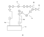
- FIG. 2 is a diagram showing the mechanism of the work support robot of FIG.
- FIG. 3 is a diagram showing a mechanism of a work support robot when a plurality of articulated arms are directed in the same direction.
- the work support robot 10 shown in FIG. 1 includes a plurality of articulated arms 12 and 14, an elevating unit 16 that elevates and elevates the plurality of articulated arms 12 and 14, respectively, and a main body unit 18 provided with the elevating unit 16.
- a moving mechanism 20 for moving the main body unit 18 to a predetermined position with respect to the target of work support is provided.
- the elevating unit 16 has a first elevating unit 16a for elevating and lowering the articulated arm 12 and a second elevating unit 16b for elevating and lowering the articulated arm 14.
- the articulated arm 12 has seven joints 12a to 12g from the side closer to the first elevating unit 16a.
- the articulated arm 14 has seven joints 14a to 14g from the side closer to the second elevating unit 16b.
- the joints 12a to 12g each have a rotation shaft 22a to 22g, and the joints 14a to 114g each have a rotation shaft 24a to 24g. That is, the articulated arm 12 has 8 degrees of freedom (7 or more degrees of freedom) including the degree of freedom of vertical movement by the first elevating unit 16a. Similarly, the articulated arm 14 has 8 degrees of freedom (7 or more degrees of freedom) including the degree of freedom of vertical movement by the second elevating unit 16b.
- the elevating unit 16 shifts the positions of the plurality of articulated arms 12 and 14 in the height direction.
- the articulated arms 12 and 14 can be oriented in the same direction without interference. Therefore, the movements and postures required for the plurality of articulated arms 12 and 14 can be realized in a small space.
- the articulated arm 12 moved above the articulated arm 14 by the first elevating unit 16a supports work while overlapping with the articulated arm 14 when viewed in the vertical direction. It is configured to be able to extend towards the subject.
- the area S obtained by projecting the articulated arm 12 and the articulated arm 14 onto the horizontal plane becomes small, and care is taken around the work support robot 10 without interfering with the articulated arms 12 and 14. It makes it easier for workers such as people and medical personnel to work.
- first elevating unit 16a and the second elevating unit 16b are provided side by side on the upper part of the main body unit 18 of the work support robot 10. As a result, the elevating unit 16 can be prevented from protruding to the side of the main body unit 18, so that the area occupied by the work support robot 10 can be reduced.
- the articulated arm 12 has a joint 12a closest to the first elevating unit 16a and a joint 12b next to the joint 12a.
- the joint 12a has a rotation shaft 22a along the vertical movement axis Za of the first elevating unit 16a.
- the rotation axis 22a along the axis Za is not only when the axis Za and the rotation axis 22a are parallel to each other, but also when the angle formed by the axis Za and the rotation axis 22a is in the range of 0 ⁇ 45 ° or 0 ⁇ . It may also include a range of 30 ° or a range of 0 ⁇ 15 °.
- the joint 12b has a rotation shaft 22b that intersects the rotation shaft 22a.
- the rotation axis 22b that intersects the rotation axis 22a is not only when the rotation axis 22a and the rotation axis 22b are orthogonal to each other, but also in a range where the angle formed by the rotation axis 22a and the rotation axis 22b is 90 ⁇ 45 °.
- the range of 90 ⁇ 30 ° or the range of 90 ⁇ 15 ° may be included.
- the work support robot 10 can be configured by the links La and Lb extending in the vertical direction from the first elevating unit 16a to the joints 12b, the joints 12b and the links La and Lb protrude to the side of the main body unit 18. The area occupied by the work support robot 10 can be reduced.
- the articulated arm 14 has a joint 14a closest to the second elevating unit 16b and a joint 14b next to the joint 14a.
- the joint 14a has a rotation shaft 24a along the vertical movement axis Zb of the second elevating unit 16b.
- the rotation axis 24a along the axis Zb is not only when the axis Zb and the rotation axis 24a are parallel to each other, but also when the angle formed by the axis Zb and the rotation axis 24a is in the range of 0 ⁇ 45 ° or 0 ⁇ . It may also include a range of 30 ° or a range of 0 ⁇ 15 °.
- the joint 14b has a rotation shaft 24b that intersects the rotation shaft 24a.
- the rotating shaft 24b that intersects the rotating shaft 24a is not only when the rotating shaft 24a and the rotating shaft 24b are orthogonal to each other, but also in a range where the angle formed by the rotating shaft 24a and the rotating shaft 24b is 90 ⁇ 45 °. Alternatively, the range of 90 ⁇ 30 ° or the range of 90 ⁇ 15 ° may be included.
- the work support robot 10 can be configured by the links L'a and L'b extending in the vertical direction from the second elevating unit 16b to the joints 14b, the joints 14b and the links L'a and L'b are the main bodies. The area occupied by the work support robot 10 can be reduced without protruding to the side of the unit 18.
- the articulated arm located above the articulated arm 12 and the articulated arm 14 can move 360 ° around the main body unit 18. Therefore, the work space in which the articulated arm can be arranged so as to reach a desired area is widened, and it becomes easy to arrange the work support robot 10 in a place where it does not easily interfere with the operator.
- the articulated arms 12 and 14 have a mounting portion 26 at the tip to which one can be selectively mounted from a plurality of types of end effectors used as surgical tools.
- Examples of the end effector used as a surgical tool include a forceps device and an endoscope.
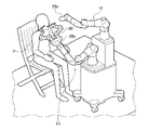
- FIG. 4 is a schematic diagram showing a state in which a patient lying on a bed is operated on by using a plurality of work support robots.
- FIG. 5 is a schematic diagram showing a state in which a patient lying on a bed is inspected using a work support robot.
- FIG. 6 is a schematic diagram showing a state in which a patient sitting on a chair is inspected using a work support robot.
- each work support robot 10a and 10b can bring a plurality of articulated arms 12 and 14 closer to each other from the same side of the patient P, which is the target of work support, instead of from both sides.
- the work support robots 10a and 10b each other based on various information such as wireless communication, GPS position information, position information of surrounding objects by radar, image data acquired by an image pickup means such as a camera, and the like. It may be configured so that the positional relationship can be grasped.
- the work support robots 10a and 10b can be placed at positions suitable for the patient P without interfering with each other. Further, the work support robots 10a and 10b can be arranged at positions that do not interfere with the doctor or the worker.
- a forceps device 28 and an endoscope are attached to the attachment portion 26 of each articulated arm shown in FIG.
- the mounting portion 26a of the articulated arm 12 may have a built-in camera for photographing the affected portion and the treated portion of the patient P. Further, a treatment tool 30 for inspecting the patient P is attached to the attachment portion 26b of the other articulated arm 14.
- FIG. 7 (a) is a schematic diagram showing a state in which the articulated arm according to the present embodiment is folded at a joint
- FIG. 7 (b) is a schematic diagram showing a state in which the articulated arm according to a modified example is folded.
- FIG. 7 (c) is a schematic view showing a state in which the articulated arm according to another modified example is folded.
- the link Le connecting the joint 12d and the joint 12e is L-shaped (see FIG. 1). Therefore, when the multi-joint arm 12 is folded at the joint 12d, the link from the joint 12a to the joint 12d and the link from the joint 12e to the joint 12g can be made substantially parallel.
- the link Ld connecting the joints 12c and the joints 12d is L-shaped. Therefore, when the multi-joint arm 12 is folded at the joint 12d, the link from the joint 12a to the joint 12c and the link from the joint 12d to the joint 12g can be made substantially parallel.
- the link Ld connecting the joint 12c and the joint 12d and the link Le connecting the joint 12d and the joint 12e are both U-shaped (V-shaped). Therefore, when the multi-joint arm 12 is folded at the joint 12d, the link from the joint 12a to the joint 12d and the link from the joint 12d to the joint 12g can be made substantially parallel.
- the present invention has been described above with reference to the above-described embodiment, the present invention is not limited to the above-described embodiment, and the present invention is not limited to the above-described embodiment, and the present invention may be a combination or a replacement of the configurations of the embodiments as appropriate. It is included in the present invention. Further, it is also possible to appropriately rearrange the combinations and the order of processing in the embodiment based on the knowledge of those skilled in the art, and to add modifications such as various design changes to the embodiments, and such modifications are added. The embodiments described above may also be included in the scope of the present invention.
- the present invention can be used for work support robots such as surgery, nursing care, manufacturing, and transportation.
Abstract
A work assistance robot 10 comprises: a plurality of multi-joint arms 12, 14; a raising/lowering unit 16 that raises/lowers each of the plurality of multi-joint arms 12, 14; and a body unit 18 to which the raising/lowering unit 16 is provided. The multi-joint arms 12, 14 have at least seven degrees of freedom, including up/down movement degrees of freedom via the raising/lowering unit 16.
Description
本発明は、作業支援ロボットに関する。
The present invention relates to a work support robot.
近年、術者の負担軽減や、医療施設の省人化を図るためにロボット(マニピュレータ)を利用した医療処置の提案がされている。外科分野では、術者が遠隔操作可能な手術用マニピュレータを操作して患者の処置を行う、手術用マニピュレータシステムに関する提案が行われている。また、土台に設けられた複数の多関節アームにより、人に対して介護・医療関連の行為をするロボットシステムも考案されている(特許文献1参照)。
In recent years, medical procedures using robots (manipulators) have been proposed in order to reduce the burden on surgeons and save labor in medical facilities. In the field of surgery, proposals have been made for a surgical manipulator system in which a surgeon operates a remotely controllable surgical manipulator to treat a patient. In addition, a robot system has been devised to perform long-term care / medical-related actions on a person by using a plurality of articulated arms provided on the base (see Patent Document 1).
しかしながら、前述のロボットシステムに設けられた2つの多関節アームは、ベッド下方に固定配置されている土台からベッドの両側を回り込むようにして人に対する処置を行うように構成されている。そのため、多関節アームを用いて人に対する処置を行っている間、介護者や医療関係者は多関節アームと干渉しないようにする必要があり、介護者や医療関係者の位置や動きに制約がある。
However, the two articulated arms provided in the robot system described above are configured to wrap around both sides of the bed from a base fixedly arranged under the bed to treat a person. Therefore, it is necessary for caregivers and medical personnel not to interfere with the articulated arm while treating a person using the articulated arm, and the position and movement of the caregiver and medical personnel are restricted. be.
本発明はこうした状況に鑑みてなされたものであり、その例示的な目的の一つは、複数の多関節アームに求められる動作や姿勢を省スペースで実現する新たな技術を提供することにある。
The present invention has been made in view of such a situation, and one of its exemplary purposes is to provide a new technique for realizing the movements and postures required for a plurality of articulated arms in a space-saving manner. ..
上記課題を解決するために、本発明のある態様の作業支援ロボットは、複数の多関節アームと、複数の多関節アームをそれぞれ昇降する昇降ユニットと、昇降ユニットが設けられている本体ユニットと、を備える。多関節アームは、昇降ユニットによる上下動の自由度を含めて7以上の自由度を有する。
In order to solve the above problems, the work support robot according to an aspect of the present invention includes a plurality of articulated arms, an elevating unit that elevates and elevates the plurality of articulated arms, and a main body unit provided with the elevating unit. To prepare for. The articulated arm has 7 or more degrees of freedom, including the degree of freedom of vertical movement by the elevating unit.
この態様によると、昇降ユニットにより複数の多関節アームのそれぞれの高さ方向の位置をずらせるので、干渉せずに多関節ユニットを同じ方向に向けることができる。そのため、複数の多関節アームに求められる動作や姿勢を省スペースで実現できる。また、複数の多関節アームを作業支援の対象の両側からではなく同じ側から近づけることができる。
According to this aspect, since the elevating unit shifts the positions of the plurality of articulated arms in the height direction, the articulated units can be oriented in the same direction without interference. Therefore, the movements and postures required for a plurality of articulated arms can be realized in a small space. Also, multiple articulated arms can be brought closer from the same side of the work support target rather than from both sides.
複数の多関節アームは、第1の多関節アームと第2の多関節アームとを有してもよい。昇降ユニットは、第1の多関節アームを昇降する第1の昇降ユニットと、第2の多関節アームを昇降する第2の昇降ユニットとを有してもよい。第1の昇降ユニットにより第2の多関節アームよりも上方に移動した第1の多関節アームは、上下方向に見て第2の多関節アームと重なりながら作業支援の対象に向けて延びることができるように構成されていてもよい。これにより、第1の多関節アームと第2の多関節アームとを水平面に投影した面積が小さくなり、多関節アームと干渉せずに作業支援ロボットの周囲で介護者や医療関係者といった作業者の作業がし易くなる。
The plurality of articulated arms may have a first articulated arm and a second articulated arm. The elevating unit may include a first elevating unit for elevating and lowering the first articulated arm and a second elevating unit for elevating and lowering the second articulated arm. The first articulated arm moved above the second articulated arm by the first elevating unit may extend toward the work support target while overlapping with the second articulated arm when viewed in the vertical direction. It may be configured so that it can be done. As a result, the area of the first articulated arm and the second articulated arm projected onto the horizontal plane becomes smaller, and workers such as caregivers and medical personnel around the work support robot without interfering with the articulated arm. It becomes easier to work.
第1の多関節アームは、第1の昇降ユニットに最も近い第1の関節と、該第1の関節の次にある第2の関節と、を有してもよい。第1の関節は、第1の昇降ユニットの上下動の軸に沿った第1の回転軸を有してもよい。第2の関節は、第1の回転軸と交差する第2の回転軸を有してもよい。これにより、第1の昇降ユニットから第2の関節まで上下方向に延びるリンクで構成できるため、作業支援ロボットの専有面積を小さくできる。
The first articulated arm may have a first joint closest to the first elevating unit and a second joint following the first joint. The first joint may have a first axis of rotation along the axis of vertical movement of the first elevating unit. The second joint may have a second axis of rotation that intersects the first axis of rotation. As a result, it is possible to configure a link extending in the vertical direction from the first elevating unit to the second joint, so that the area occupied by the work support robot can be reduced.
第2の多関節アームは、第2の昇降ユニットに最も近い第3の関節と、該第3の関節の次にある第4の関節と、を有してもよい。第3の関節は、第2の昇降ユニットの上下動の軸に沿った第3の回転軸を有してもよい。第4の関節は、第3の回転軸と交差する第4の回転軸を有してもよい。これにより、第2の昇降ユニットから第4の関節まで上下方向に延びるリンクで構成できるため、作業支援ロボットの専有面積を小さくできる。
The second articulated arm may have a third joint closest to the second elevating unit and a fourth joint following the third joint. The third joint may have a third axis of rotation along the axis of vertical movement of the second elevating unit. The fourth joint may have a fourth axis of rotation that intersects the third axis of rotation. As a result, it is possible to configure a link extending in the vertical direction from the second elevating unit to the fourth joint, so that the area occupied by the work support robot can be reduced.
第1の昇降ユニット及び第2の昇降ユニットは、本体ユニットの上部に並んで設けられていてもよい。これにより、昇降ユニットが本体ユニットの側方にはみ出さないようにできるため、作業支援ロボットの専有面積を小さくできる。
The first elevating unit and the second elevating unit may be provided side by side on the upper part of the main body unit. As a result, the elevating unit can be prevented from protruding to the side of the main body unit, so that the area occupied by the work support robot can be reduced.
本体ユニットを作業支援の対象に対して所定の位置に移動するための移動機構を更に備えてもよい。これにより、作業者と干渉しない位置に作業支援ロボットを配置できる。
A moving mechanism for moving the main body unit to a predetermined position with respect to the target of work support may be further provided. As a result, the work support robot can be placed at a position that does not interfere with the worker.
多関節アームは、術具として用いる複数種のエンドエフェクタから一つを選択的に装着できる装着部を先端に有してもよい。
The articulated arm may have a mounting portion at the tip to which one of a plurality of types of end effectors used as a surgical tool can be selectively mounted.
なお、以上の構成要素の任意の組合せ、本発明の表現を方法、装置、システム、などの間で変換したものもまた、本発明の態様として有効である。
It should be noted that any combination of the above components and the conversion of the expression of the present invention between methods, devices, systems, etc. are also effective as aspects of the present invention.
本発明によれば、複数の多関節アームに求められる動作や姿勢を省スペースで実現できる。
According to the present invention, the movements and postures required for a plurality of articulated arms can be realized in a small space.
以下、本発明を実施の形態をもとに図面を参照しながら説明する。各図面に示される同一又は同等の構成要素、部材、処理には、同一の符号を付するものとし、適宜重複した説明は省略する。また、実施の形態は、発明を限定するものではなく例示であって、実施の形態に記述される全ての特徴やその組合せは、必ずしも発明の本質的なものであるとは限らない。
Hereinafter, the present invention will be described with reference to the drawings based on the embodiments. The same or equivalent components, members, and processes shown in the drawings shall be designated by the same reference numerals, and duplicate description thereof will be omitted as appropriate. Further, the embodiment is not limited to the invention, but is an example, and all the features and combinations thereof described in the embodiment are not necessarily essential to the invention.
図1は、本実施の形態に係る作業支援ロボットの斜視図である。図2は、図1の作業支援ロボットの機構を示す図である。図3は、複数の多関節アームを同じ方向に向けた場合の作業支援ロボットの機構を示す図である。図1に示す作業支援ロボット10は、複数の多関節アーム12,14と、複数の多関節アーム12,14をそれぞれ昇降する昇降ユニット16と、昇降ユニット16が設けられている本体ユニット18と、本体ユニット18を作業支援の対象に対して所定の位置に移動するための移動機構20と、を備える。
FIG. 1 is a perspective view of a work support robot according to the present embodiment. FIG. 2 is a diagram showing the mechanism of the work support robot of FIG. FIG. 3 is a diagram showing a mechanism of a work support robot when a plurality of articulated arms are directed in the same direction. The work support robot 10 shown in FIG. 1 includes a plurality of articulated arms 12 and 14, an elevating unit 16 that elevates and elevates the plurality of articulated arms 12 and 14, respectively, and a main body unit 18 provided with the elevating unit 16. A moving mechanism 20 for moving the main body unit 18 to a predetermined position with respect to the target of work support is provided.
昇降ユニット16は、多関節アーム12を昇降する第1の昇降ユニット16aと、多関節アーム14を昇降する第2の昇降ユニット16bとを有している。多関節アーム12は、第1の昇降ユニット16aに近い側から7つの関節12a~12gを有している。多関節アーム14は、第2の昇降ユニット16bに近い側から7つの関節14a~14gを有している。
The elevating unit 16 has a first elevating unit 16a for elevating and lowering the articulated arm 12 and a second elevating unit 16b for elevating and lowering the articulated arm 14. The articulated arm 12 has seven joints 12a to 12g from the side closer to the first elevating unit 16a. The articulated arm 14 has seven joints 14a to 14g from the side closer to the second elevating unit 16b.
関節12a~12gは、それぞれ回転軸22a~22gを有しており、関節14a~114gは、それぞれ回転軸24a~24gを有している。つまり、多関節アーム12は、第1の昇降ユニット16aによる上下動の自由度を含めて8自由度(7以上の自由度)を有する。同様に、多関節アーム14は、第2の昇降ユニット16bによる上下動の自由度を含めて8自由度(7以上の自由度)を有する。
The joints 12a to 12g each have a rotation shaft 22a to 22g, and the joints 14a to 114g each have a rotation shaft 24a to 24g. That is, the articulated arm 12 has 8 degrees of freedom (7 or more degrees of freedom) including the degree of freedom of vertical movement by the first elevating unit 16a. Similarly, the articulated arm 14 has 8 degrees of freedom (7 or more degrees of freedom) including the degree of freedom of vertical movement by the second elevating unit 16b.
このように、本実施の形態に係る作業支援ロボット10は、図1や図3に示すように、昇降ユニット16により複数の多関節アーム12,14のそれぞれの高さ方向の位置をずらせるので、干渉せずに多関節アーム12,14を同じ方向に向けることができる。そのため、複数の多関節アーム12,14に求められる動作や姿勢を省スペースで実現できる。
As described above, in the work support robot 10 according to the present embodiment, as shown in FIGS. 1 and 3, the elevating unit 16 shifts the positions of the plurality of articulated arms 12 and 14 in the height direction. , The articulated arms 12 and 14 can be oriented in the same direction without interference. Therefore, the movements and postures required for the plurality of articulated arms 12 and 14 can be realized in a small space.
また、図1や図3に示すように、第1の昇降ユニット16aにより多関節アーム14よりも上方に移動した多関節アーム12は、上下方向に見て多関節アーム14と重なりながら作業支援の対象に向けて延びることができるように構成されている。これにより、図1に示すように、多関節アーム12と多関節アーム14とを水平面に投影した面積Sが小さくなり、多関節アーム12,14と干渉せずに作業支援ロボット10の周囲で介護者や医療関係者といった作業者の作業がし易くなる。
Further, as shown in FIGS. 1 and 3, the articulated arm 12 moved above the articulated arm 14 by the first elevating unit 16a supports work while overlapping with the articulated arm 14 when viewed in the vertical direction. It is configured to be able to extend towards the subject. As a result, as shown in FIG. 1, the area S obtained by projecting the articulated arm 12 and the articulated arm 14 onto the horizontal plane becomes small, and care is taken around the work support robot 10 without interfering with the articulated arms 12 and 14. It makes it easier for workers such as people and medical personnel to work.
また、第1の昇降ユニット16a及び第2の昇降ユニット16bは、作業支援ロボット10の本体ユニット18の上部に並んで設けられている。これにより、昇降ユニット16が本体ユニット18の側方にはみ出さないようにできるため、作業支援ロボット10の専有面積を小さくできる。
Further, the first elevating unit 16a and the second elevating unit 16b are provided side by side on the upper part of the main body unit 18 of the work support robot 10. As a result, the elevating unit 16 can be prevented from protruding to the side of the main body unit 18, so that the area occupied by the work support robot 10 can be reduced.
また、多関節アーム12は、第1の昇降ユニット16aに最も近い関節12aと、関節12aの次にある関節12bと、を有している。関節12aは、第1の昇降ユニット16aの上下動の軸Zaに沿った回転軸22aを有している。ここで、軸Zaに沿った回転軸22aとは、軸Zaと回転軸22aとが平行な場合だけでなく、軸Zaと回転軸22aとの成す角が0±45°の範囲、あるいは0±30°の範囲、あるいは0±15°の範囲の場合も含み得る。
Further, the articulated arm 12 has a joint 12a closest to the first elevating unit 16a and a joint 12b next to the joint 12a. The joint 12a has a rotation shaft 22a along the vertical movement axis Za of the first elevating unit 16a. Here, the rotation axis 22a along the axis Za is not only when the axis Za and the rotation axis 22a are parallel to each other, but also when the angle formed by the axis Za and the rotation axis 22a is in the range of 0 ± 45 ° or 0 ±. It may also include a range of 30 ° or a range of 0 ± 15 °.
関節12bは、回転軸22aと交差する回転軸22bを有している。ここで、回転軸22aと交差する回転軸22bとは、回転軸22aと回転軸22bとが直交する場合だけでなく、回転軸22aと回転軸22bとの成す角が90±45°の範囲、あるいは90±30°の範囲、あるいは90±15°の範囲の場合も含み得る。このように、作業支援ロボット10は、第1の昇降ユニット16aから関節12bまで上下方向に延びるリンクLa,Lbで構成できるため、関節12bやリンクLa,Lbが本体ユニット18の側方にはみ出ることがなく、作業支援ロボット10の専有面積を小さくできる。
The joint 12b has a rotation shaft 22b that intersects the rotation shaft 22a. Here, the rotation axis 22b that intersects the rotation axis 22a is not only when the rotation axis 22a and the rotation axis 22b are orthogonal to each other, but also in a range where the angle formed by the rotation axis 22a and the rotation axis 22b is 90 ± 45 °. Alternatively, the range of 90 ± 30 ° or the range of 90 ± 15 ° may be included. As described above, since the work support robot 10 can be configured by the links La and Lb extending in the vertical direction from the first elevating unit 16a to the joints 12b, the joints 12b and the links La and Lb protrude to the side of the main body unit 18. The area occupied by the work support robot 10 can be reduced.
また、多関節アーム14は、第2の昇降ユニット16bに最も近い関節14aと、関節14aの次にある関節14bと、を有している。関節14aは、第2の昇降ユニット16bの上下動の軸Zbに沿った回転軸24aを有している。ここで、軸Zbに沿った回転軸24aとは、軸Zbと回転軸24aとが平行な場合だけでなく、軸Zbと回転軸24aとの成す角が0±45°の範囲、あるいは0±30°の範囲、あるいは0±15°の範囲の場合も含み得る。
Further, the articulated arm 14 has a joint 14a closest to the second elevating unit 16b and a joint 14b next to the joint 14a. The joint 14a has a rotation shaft 24a along the vertical movement axis Zb of the second elevating unit 16b. Here, the rotation axis 24a along the axis Zb is not only when the axis Zb and the rotation axis 24a are parallel to each other, but also when the angle formed by the axis Zb and the rotation axis 24a is in the range of 0 ± 45 ° or 0 ±. It may also include a range of 30 ° or a range of 0 ± 15 °.
関節14bは、回転軸24aと交差する回転軸24bを有している。ここで、回転軸24aと交差する回転軸24bとは、回転軸24aと回転軸24bとが直交する場合だけでなく、回転軸24aと回転軸24bとの成す角が90±45°の範囲、あるいは90±30°の範囲、あるいは90±15°の範囲の場合も含み得る。このように、作業支援ロボット10は、第2の昇降ユニット16bから関節14bまで上下方向に延びるリンクL’a,L’bで構成できるため、関節14bやリンクL’a,L’bが本体ユニット18の側方にはみ出ることがなく、作業支援ロボット10の専有面積を小さくできる。
The joint 14b has a rotation shaft 24b that intersects the rotation shaft 24a. Here, the rotating shaft 24b that intersects the rotating shaft 24a is not only when the rotating shaft 24a and the rotating shaft 24b are orthogonal to each other, but also in a range where the angle formed by the rotating shaft 24a and the rotating shaft 24b is 90 ± 45 °. Alternatively, the range of 90 ± 30 ° or the range of 90 ± 15 ° may be included. As described above, since the work support robot 10 can be configured by the links L'a and L'b extending in the vertical direction from the second elevating unit 16b to the joints 14b, the joints 14b and the links L'a and L'b are the main bodies. The area occupied by the work support robot 10 can be reduced without protruding to the side of the unit 18.
また、作業支援ロボット10では、多関節アーム12および多関節アーム14のうち上方に位置する多関節アームが本体ユニット18の周囲の360°に渡って動くことができる。そのため、多関節アームが所望の領域に届くように配置できる作業スペースが広がり、作業支援ロボット10を作業者と干渉しにくい場所に配置し易くなる。
Further, in the work support robot 10, the articulated arm located above the articulated arm 12 and the articulated arm 14 can move 360 ° around the main body unit 18. Therefore, the work space in which the articulated arm can be arranged so as to reach a desired area is widened, and it becomes easy to arrange the work support robot 10 in a place where it does not easily interfere with the operator.
なお、多関節アーム12,14は、術具として用いる複数種のエンドエフェクタから一つを選択的に装着できる装着部26を先端に有している。術具として用いるエンドエフェクタは、例えば、鉗子装置や内視鏡が挙げられる。
The articulated arms 12 and 14 have a mounting portion 26 at the tip to which one can be selectively mounted from a plurality of types of end effectors used as surgical tools. Examples of the end effector used as a surgical tool include a forceps device and an endoscope.
次に、作業支援ロボット10の使用態様について説明する。図4は、ベッドに横たわる患者を複数の作業支援ロボットを用いて手術する様子を示す模式図である。図5は、ベッドに横たわる患者を作業支援ロボットを用いて検査する様子を示す模式図である。図6は、椅子に座っている患者を作業支援ロボット用いて検査する様子を示す模式図である。
Next, the usage mode of the work support robot 10 will be described. FIG. 4 is a schematic diagram showing a state in which a patient lying on a bed is operated on by using a plurality of work support robots. FIG. 5 is a schematic diagram showing a state in which a patient lying on a bed is inspected using a work support robot. FIG. 6 is a schematic diagram showing a state in which a patient sitting on a chair is inspected using a work support robot.
図4に示すように、各作業支援ロボット10a,10bは、それぞれ複数の多関節アーム12,14を作業支援の対象である患者Pの両側からではなく同じ側から近づけることができる。また、各作業支援ロボット10a,10bは、無線通信、GPSの位置情報、レーダによる周囲の物体の位置情報、カメラ等の撮像手段で取得した画像データ、等の種々の情報に基づいて、互いの位置関係を把握できるように構成されていてもよい。
As shown in FIG. 4, each work support robot 10a and 10b can bring a plurality of articulated arms 12 and 14 closer to each other from the same side of the patient P, which is the target of work support, instead of from both sides. Further, the work support robots 10a and 10b each other based on various information such as wireless communication, GPS position information, position information of surrounding objects by radar, image data acquired by an image pickup means such as a camera, and the like. It may be configured so that the positional relationship can be grasped.
これにより、作業支援ロボット10a,10bが互いに干渉することなく、患者Pに対して適した位置に作業支援ロボットを配置できる。また、医者や作業者と干渉しない位置に作業支援ロボット10a,10bを配置できる。なお、図4に示す各多関節アームの装着部26には、鉗子装置28や内視鏡が装着されている。
As a result, the work support robots 10a and 10b can be placed at positions suitable for the patient P without interfering with each other. Further, the work support robots 10a and 10b can be arranged at positions that do not interfere with the doctor or the worker. A forceps device 28 and an endoscope are attached to the attachment portion 26 of each articulated arm shown in FIG.
また、図5や図6に示すように、多関節アーム12の装着部26aには患者Pの患部や処置部を撮像するカメラが内蔵されていてもよい。また、もう一方の多関節アーム14の装着部26bには、患者Pを検査するための処置具30が装着されている。
Further, as shown in FIGS. 5 and 6, the mounting portion 26a of the articulated arm 12 may have a built-in camera for photographing the affected portion and the treated portion of the patient P. Further, a treatment tool 30 for inspecting the patient P is attached to the attachment portion 26b of the other articulated arm 14.
(アームの折りたたみ)
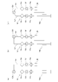
図7(a)は、本実施の形態に係る多関節アームが関節で折りたたまれた状態を示す模式図、図7(b)は、変形例に係る多関節アームが折りたたまれた状態を示す模式図、図7(c)は、他の変形例に係る多関節アームが折りたたまれた状態を示す模式図である。 (Folding the arm)
FIG. 7 (a) is a schematic diagram showing a state in which the articulated arm according to the present embodiment is folded at a joint, and FIG. 7 (b) is a schematic diagram showing a state in which the articulated arm according to a modified example is folded. FIG. 7 (c) is a schematic view showing a state in which the articulated arm according to another modified example is folded.
図7(a)に示す多関節アーム12では、関節12dと関節12eとを連結するリンクLeがL字状(図1参照)である。そのため、多関節アーム12を関節12dで折りたたんだ場合に、関節12aから関節12dまでのリンクと、関節12eから関節12gまでのリンクとをほぼ平行にできる。
In the multi-joint arm 12 shown in FIG. 7 (a), the link Le connecting the joint 12d and the joint 12e is L-shaped (see FIG. 1). Therefore, when the multi-joint arm 12 is folded at the joint 12d, the link from the joint 12a to the joint 12d and the link from the joint 12e to the joint 12g can be made substantially parallel.
図7(b)に示す多関節アーム12では、関節12cと関節12dとを連結するリンクLdがL字状である。そのため、多関節アーム12を関節12dで折りたたんだ場合に、関節12aから関節12cまでのリンクと、関節12dから関節12gまでのリンクとをほぼ平行にできる。
In the articulated arm 12 shown in FIG. 7B, the link Ld connecting the joints 12c and the joints 12d is L-shaped. Therefore, when the multi-joint arm 12 is folded at the joint 12d, the link from the joint 12a to the joint 12c and the link from the joint 12d to the joint 12g can be made substantially parallel.
図7(c)に示す多関節アーム12では、関節12cと関節12dとを連結するリンクLd及び関節12dと関節12eとを連結するリンクLeが併せてU字状(V字状)である。そのため、多関節アーム12を関節12dで折りたたんだ場合に、関節12aから関節12dまでのリンクと、関節12dから関節12gまでのリンクとをほぼ平行にできる。
In the multi-joint arm 12 shown in FIG. 7 (c), the link Ld connecting the joint 12c and the joint 12d and the link Le connecting the joint 12d and the joint 12e are both U-shaped (V-shaped). Therefore, when the multi-joint arm 12 is folded at the joint 12d, the link from the joint 12a to the joint 12d and the link from the joint 12d to the joint 12g can be made substantially parallel.
以上、本発明を上述の実施の形態を参照して説明したが、本発明は上述の実施の形態に限定されるものではなく、実施の形態の構成を適宜組み合わせたものや置換したものについても本発明に含まれるものである。また、当業者の知識に基づいて実施の形態における組合せや処理の順番を適宜組み替えることや各種の設計変更等の変形を実施の形態に対して加えることも可能であり、そのような変形が加えられた実施の形態も本発明の範囲に含まれうる。
Although the present invention has been described above with reference to the above-described embodiment, the present invention is not limited to the above-described embodiment, and the present invention is not limited to the above-described embodiment, and the present invention may be a combination or a replacement of the configurations of the embodiments as appropriate. It is included in the present invention. Further, it is also possible to appropriately rearrange the combinations and the order of processing in the embodiment based on the knowledge of those skilled in the art, and to add modifications such as various design changes to the embodiments, and such modifications are added. The embodiments described above may also be included in the scope of the present invention.
本発明は、手術や介護、製造、運搬等の作業支援ロボットに利用できる。
The present invention can be used for work support robots such as surgery, nursing care, manufacturing, and transportation.
10 作業支援ロボット、 12 多関節アーム、 12a,12b,12c,12d,12e,12f,12g 関節、 14 多関節アーム、 14a,14b,14c,14d,14e,14f,14g 関節、 16 昇降ユニット、 16a 第1の昇降ユニット、 16b 第2の昇降ユニット、 18 本体ユニット、 20 移動機構、 22a,22b 回転軸、 26,26a 装着部。
10 work support robot, 12 articulated arm, 12a, 12b, 12c, 12d, 12e, 12f, 12g joint, 14 articulated arm, 14a, 14b, 14c, 14d, 14e, 14f, 14g joint, 16 elevating unit, 16a 1st elevating unit, 16b 2nd elevating unit, 18 main body unit, 20 moving mechanism, 22a, 22b rotating shaft, 26, 26a mounting part.
Claims (7)
- 複数の多関節アームと、
前記複数の多関節アームをそれぞれ昇降する昇降ユニットと、
前記昇降ユニットが設けられている本体ユニットと、を備え、
前記多関節アームは、前記昇降ユニットによる上下動の自由度を含めて7以上の自由度を有することを特徴とする作業支援ロボット。 With multiple articulated arms,
An elevating unit that raises and lowers each of the plurality of articulated arms,
With a main body unit provided with the elevating unit,
The articulated arm is a work support robot having 7 or more degrees of freedom including the degree of freedom of vertical movement by the elevating unit. - 前記複数の多関節アームは、第1の多関節アームと第2の多関節アームとを有し、
前記昇降ユニットは、前記第1の多関節アームを昇降する第1の昇降ユニットと、前記第2の多関節アームを昇降する第2の昇降ユニットとを有し、
前記第1の昇降ユニットにより前記第2の多関節アームよりも上方に移動した第1の多関節アームは、上下方向に見て前記第2の多関節アームと重なりながら作業支援の対象に向けて延びることができるように構成されていることを特徴とする請求項1に記載の作業支援ロボット。 The plurality of articulated arms have a first articulated arm and a second articulated arm.
The elevating unit has a first elevating unit for elevating and lowering the first articulated arm and a second elevating unit for elevating and lowering the second articulated arm.
The first articulated arm moved above the second articulated arm by the first elevating unit is directed toward the work support target while overlapping with the second articulated arm when viewed in the vertical direction. The work support robot according to claim 1, wherein the robot is configured to be extendable. - 前記第1の多関節アームは、前記第1の昇降ユニットに最も近い第1の関節と、該第1の関節の次にある第2の関節と、を有し、
前記第1の関節は、前記第1の昇降ユニットの上下動の軸に沿った第1の回転軸を有し、
前記第2の関節は、前記第1の回転軸と交差する第2の回転軸を有することを特徴とする請求項2に記載の作業支援ロボット。 The first articulated arm has a first joint closest to the first elevating unit and a second joint following the first joint.
The first joint has a first axis of rotation along the axis of vertical movement of the first elevating unit.
The work support robot according to claim 2, wherein the second joint has a second rotation axis that intersects with the first rotation axis. - 前記第2の多関節アームは、前記第2の昇降ユニットに最も近い第3の関節と、該第3の関節の次にある第4の関節と、を有し、
前記第3の関節は、前記第2の昇降ユニットの上下動の軸に沿った第3の回転軸を有し、
前記第4の関節は、前記第3の回転軸と交差する第4の回転軸を有することを特徴とする請求項3に記載の作業支援ロボット。 The second articulated arm has a third joint closest to the second elevating unit and a fourth joint following the third joint.
The third joint has a third axis of rotation along the axis of vertical movement of the second elevating unit.
The work support robot according to claim 3, wherein the fourth joint has a fourth rotation axis that intersects with the third rotation axis. - 前記第1の昇降ユニット及び前記第2の昇降ユニットは、前記本体ユニットの上部に並んで設けられていることを特徴とする請求項2乃至4のいずれか1項に記載の作業支援ロボット。 The work support robot according to any one of claims 2 to 4, wherein the first elevating unit and the second elevating unit are provided side by side on the upper part of the main body unit.
- 前記本体ユニットを作業支援の対象に対して所定の位置に移動するための移動機構を更に備えることを特徴とする請求項1乃至5のいずれか1項に記載の作業支援ロボット。 The work support robot according to any one of claims 1 to 5, further comprising a movement mechanism for moving the main body unit to a predetermined position with respect to the target of work support.
- 前記多関節アームは、術具として用いる複数種のエンドエフェクタから一つを選択的に装着できる装着部を先端に有することを特徴とする請求項1乃至6のいずれか1項に記載の作業支援ロボット。 The work support according to any one of claims 1 to 6, wherein the articulated arm has a mounting portion at the tip to which one of a plurality of types of end effectors used as a surgical tool can be selectively mounted. robot.
Priority Applications (5)
| Application Number | Priority Date | Filing Date | Title |
|---|---|---|---|
| JP2022532649A JP7200458B2 (en) | 2020-10-15 | 2020-10-15 | Work support robot |
| CN202080106119.0A CN116367968A (en) | 2020-10-15 | 2020-10-15 | Robot is assisted in operation |
| EP20957704.8A EP4223459A4 (en) | 2020-10-15 | 2020-10-15 | Work assistance robot |
| PCT/JP2020/038998 WO2022079875A1 (en) | 2020-10-15 | 2020-10-15 | Work assistance robot |
| US18/300,054 US20230256590A1 (en) | 2020-10-15 | 2023-04-13 | Work assistance robot |
Applications Claiming Priority (1)
| Application Number | Priority Date | Filing Date | Title |
|---|---|---|---|
| PCT/JP2020/038998 WO2022079875A1 (en) | 2020-10-15 | 2020-10-15 | Work assistance robot |
Related Child Applications (1)
| Application Number | Title | Priority Date | Filing Date |
|---|---|---|---|
| US18/300,054 Continuation US20230256590A1 (en) | 2020-10-15 | 2023-04-13 | Work assistance robot |
Publications (1)
| Publication Number | Publication Date |
|---|---|
| WO2022079875A1 true WO2022079875A1 (en) | 2022-04-21 |
Family
ID=81208999
Family Applications (1)
| Application Number | Title | Priority Date | Filing Date |
|---|---|---|---|
| PCT/JP2020/038998 WO2022079875A1 (en) | 2020-10-15 | 2020-10-15 | Work assistance robot |
Country Status (5)
| Country | Link |
|---|---|
| US (1) | US20230256590A1 (en) |
| EP (1) | EP4223459A4 (en) |
| JP (1) | JP7200458B2 (en) |
| CN (1) | CN116367968A (en) |
| WO (1) | WO2022079875A1 (en) |
Citations (7)
| Publication number | Priority date | Publication date | Assignee | Title |
|---|---|---|---|---|
| JPH0870033A (en) * | 1994-08-26 | 1996-03-12 | Kokusai Electric Co Ltd | Wafer transfer machine of semiconductor manufacturing device |
| US20010013764A1 (en) * | 1998-08-04 | 2001-08-16 | Blumenkranz Steven J. | Manipulator positioning linkage for robotic surgery |
| JP2009525098A (en) * | 2006-02-03 | 2009-07-09 | ザ ヨーロピアン アトミック エナジー コミュニティ(ユーラトム)、リプリゼンテッド バイ ザ ヨーロピアン コミッション | Robotic surgical system for performing minimally invasive medical procedures |
| JP2011206312A (en) * | 2010-03-30 | 2011-10-20 | Terumo Corp | Medical robot system |
| WO2017002142A1 (en) | 2015-06-29 | 2017-01-05 | 川崎重工業株式会社 | Robot system |
| CN109730778A (en) * | 2019-03-20 | 2019-05-10 | 苏州康多机器人有限公司 | A kind of the laparoscopic surgery robot and system of double control cooperating |
| JP2020065644A (en) * | 2018-10-23 | 2020-04-30 | 株式会社A−Traction | Surgery assistance apparatus, control method thereof and program |
Family Cites Families (3)
| Publication number | Priority date | Publication date | Assignee | Title |
|---|---|---|---|---|
| WO2016142981A1 (en) | 2015-03-06 | 2016-09-15 | 株式会社日立製作所 | Work robot and gripper |
| DE102016004840A1 (en) * | 2016-04-24 | 2017-10-26 | Kastanienbaum GmbH | Mobile robot |
| EP3934558A4 (en) | 2019-03-07 | 2022-12-14 | PROCEPT BioRobotics Corporation | Robotic arms and methods for tissue resection and imaging |
-
2020
- 2020-10-15 EP EP20957704.8A patent/EP4223459A4/en active Pending
- 2020-10-15 JP JP2022532649A patent/JP7200458B2/en active Active
- 2020-10-15 WO PCT/JP2020/038998 patent/WO2022079875A1/en unknown
- 2020-10-15 CN CN202080106119.0A patent/CN116367968A/en active Pending
-
2023
- 2023-04-13 US US18/300,054 patent/US20230256590A1/en active Pending
Patent Citations (7)
| Publication number | Priority date | Publication date | Assignee | Title |
|---|---|---|---|---|
| JPH0870033A (en) * | 1994-08-26 | 1996-03-12 | Kokusai Electric Co Ltd | Wafer transfer machine of semiconductor manufacturing device |
| US20010013764A1 (en) * | 1998-08-04 | 2001-08-16 | Blumenkranz Steven J. | Manipulator positioning linkage for robotic surgery |
| JP2009525098A (en) * | 2006-02-03 | 2009-07-09 | ザ ヨーロピアン アトミック エナジー コミュニティ(ユーラトム)、リプリゼンテッド バイ ザ ヨーロピアン コミッション | Robotic surgical system for performing minimally invasive medical procedures |
| JP2011206312A (en) * | 2010-03-30 | 2011-10-20 | Terumo Corp | Medical robot system |
| WO2017002142A1 (en) | 2015-06-29 | 2017-01-05 | 川崎重工業株式会社 | Robot system |
| JP2020065644A (en) * | 2018-10-23 | 2020-04-30 | 株式会社A−Traction | Surgery assistance apparatus, control method thereof and program |
| CN109730778A (en) * | 2019-03-20 | 2019-05-10 | 苏州康多机器人有限公司 | A kind of the laparoscopic surgery robot and system of double control cooperating |
Non-Patent Citations (1)
| Title |
|---|
| See also references of EP4223459A4 |
Also Published As
| Publication number | Publication date |
|---|---|
| EP4223459A1 (en) | 2023-08-09 |
| EP4223459A4 (en) | 2023-11-22 |
| JPWO2022079875A1 (en) | 2022-04-21 |
| JP7200458B2 (en) | 2023-01-10 |
| US20230256590A1 (en) | 2023-08-17 |
| CN116367968A (en) | 2023-06-30 |
Similar Documents
| Publication | Publication Date | Title |
|---|---|---|
| JP7273003B2 (en) | Redundant Axes and Degrees of Freedom for Hardware Constrained Remote Center Robotic Manipulators | |
| JP7263441B2 (en) | Aspects of Surgical Instrument Manipulator | |
| US20220087757A1 (en) | Surgical Arm | |
| US11267141B2 (en) | Articulation for surgical robot | |
| JP2018516656A (en) | Torque sensing in a list of surgical robots | |
| JP2017537663A (en) | Integrated operating table system and method | |
| KR102206647B1 (en) | Robot arm structure and manipulator for surgical robot comprising the same | |
| KR20180090331A (en) | Surgical Surgical System | |
| WO2022079875A1 (en) | Work assistance robot | |
| Ai et al. | Design of a novel robotic system for minimally invasive surgery | |
| RU2753118C2 (en) | Robotic system for holding and moving surgical instrument during laparoscopic operations | |
| KR20180090330A (en) | Surgical Surgical System |
Legal Events
| Date | Code | Title | Description |
|---|---|---|---|
| ENP | Entry into the national phase |
Ref document number: 2022532649 Country of ref document: JP Kind code of ref document: A |
|
| 121 | Ep: the epo has been informed by wipo that ep was designated in this application |
Ref document number: 20957704 Country of ref document: EP Kind code of ref document: A1 |
|
| ENP | Entry into the national phase |
Ref document number: 2020957704 Country of ref document: EP Effective date: 20230502 |
|
| NENP | Non-entry into the national phase |
Ref country code: DE |