WO2022079875A1 - Robot d'assistance au travail - Google Patents
Robot d'assistance au travail Download PDFInfo
- Publication number
- WO2022079875A1 WO2022079875A1 PCT/JP2020/038998 JP2020038998W WO2022079875A1 WO 2022079875 A1 WO2022079875 A1 WO 2022079875A1 JP 2020038998 W JP2020038998 W JP 2020038998W WO 2022079875 A1 WO2022079875 A1 WO 2022079875A1
- Authority
- WO
- WIPO (PCT)
- Prior art keywords
- joint
- articulated arm
- elevating unit
- work support
- articulated
- Prior art date
Links
- 230000003028 elevating effect Effects 0.000 claims description 59
- 239000012636 effector Substances 0.000 claims description 4
- 238000010586 diagram Methods 0.000 description 12
- 238000000034 method Methods 0.000 description 4
- 230000036544 posture Effects 0.000 description 4
- 230000002452 interceptive effect Effects 0.000 description 3
- 238000012986 modification Methods 0.000 description 2
- 230000004048 modification Effects 0.000 description 2
- 238000001356 surgical procedure Methods 0.000 description 2
- 238000006243 chemical reaction Methods 0.000 description 1
- 238000004891 communication Methods 0.000 description 1
- 238000013461 design Methods 0.000 description 1
- 230000007774 longterm Effects 0.000 description 1
- 238000004519 manufacturing process Methods 0.000 description 1
- 230000000474 nursing effect Effects 0.000 description 1
- 238000012545 processing Methods 0.000 description 1
Images


Classifications
-
- B—PERFORMING OPERATIONS; TRANSPORTING
- B25—HAND TOOLS; PORTABLE POWER-DRIVEN TOOLS; MANIPULATORS
- B25J—MANIPULATORS; CHAMBERS PROVIDED WITH MANIPULATION DEVICES
- B25J18/00—Arms
- B25J18/02—Arms extensible
- B25J18/04—Arms extensible rotatable
-
- A—HUMAN NECESSITIES
- A61—MEDICAL OR VETERINARY SCIENCE; HYGIENE
- A61B—DIAGNOSIS; SURGERY; IDENTIFICATION
- A61B34/00—Computer-aided surgery; Manipulators or robots specially adapted for use in surgery
- A61B34/30—Surgical robots
-
- A—HUMAN NECESSITIES
- A61—MEDICAL OR VETERINARY SCIENCE; HYGIENE
- A61B—DIAGNOSIS; SURGERY; IDENTIFICATION
- A61B90/00—Instruments, implements or accessories specially adapted for surgery or diagnosis and not covered by any of the groups A61B1/00 - A61B50/00, e.g. for luxation treatment or for protecting wound edges
- A61B90/50—Supports for surgical instruments, e.g. articulated arms
-
- B—PERFORMING OPERATIONS; TRANSPORTING
- B25—HAND TOOLS; PORTABLE POWER-DRIVEN TOOLS; MANIPULATORS
- B25J—MANIPULATORS; CHAMBERS PROVIDED WITH MANIPULATION DEVICES
- B25J15/00—Gripping heads and other end effectors
- B25J15/04—Gripping heads and other end effectors with provision for the remote detachment or exchange of the head or parts thereof
-
- B—PERFORMING OPERATIONS; TRANSPORTING
- B25—HAND TOOLS; PORTABLE POWER-DRIVEN TOOLS; MANIPULATORS
- B25J—MANIPULATORS; CHAMBERS PROVIDED WITH MANIPULATION DEVICES
- B25J5/00—Manipulators mounted on wheels or on carriages
- B25J5/007—Manipulators mounted on wheels or on carriages mounted on wheels
-
- B—PERFORMING OPERATIONS; TRANSPORTING
- B25—HAND TOOLS; PORTABLE POWER-DRIVEN TOOLS; MANIPULATORS
- B25J—MANIPULATORS; CHAMBERS PROVIDED WITH MANIPULATION DEVICES
- B25J9/00—Programme-controlled manipulators
- B25J9/0084—Programme-controlled manipulators comprising a plurality of manipulators
- B25J9/0087—Dual arms
-
- B—PERFORMING OPERATIONS; TRANSPORTING
- B25—HAND TOOLS; PORTABLE POWER-DRIVEN TOOLS; MANIPULATORS
- B25J—MANIPULATORS; CHAMBERS PROVIDED WITH MANIPULATION DEVICES
- B25J9/00—Programme-controlled manipulators
- B25J9/06—Programme-controlled manipulators characterised by multi-articulated arms
Definitions
- the present invention relates to a work support robot.
- the two articulated arms provided in the robot system described above are configured to wrap around both sides of the bed from a base fixedly arranged under the bed to treat a person. Therefore, it is necessary for caregivers and medical personnel not to interfere with the articulated arm while treating a person using the articulated arm, and the position and movement of the caregiver and medical personnel are restricted. be.
- the present invention has been made in view of such a situation, and one of its exemplary purposes is to provide a new technique for realizing the movements and postures required for a plurality of articulated arms in a space-saving manner. ..
- the work support robot includes a plurality of articulated arms, an elevating unit that elevates and elevates the plurality of articulated arms, and a main body unit provided with the elevating unit.
- the articulated arm has 7 or more degrees of freedom, including the degree of freedom of vertical movement by the elevating unit.
- the elevating unit shifts the positions of the plurality of articulated arms in the height direction
- the articulated units can be oriented in the same direction without interference. Therefore, the movements and postures required for a plurality of articulated arms can be realized in a small space. Also, multiple articulated arms can be brought closer from the same side of the work support target rather than from both sides.
- the plurality of articulated arms may have a first articulated arm and a second articulated arm.
- the elevating unit may include a first elevating unit for elevating and lowering the first articulated arm and a second elevating unit for elevating and lowering the second articulated arm.
- the first articulated arm moved above the second articulated arm by the first elevating unit may extend toward the work support target while overlapping with the second articulated arm when viewed in the vertical direction. It may be configured so that it can be done. As a result, the area of the first articulated arm and the second articulated arm projected onto the horizontal plane becomes smaller, and workers such as caregivers and medical personnel around the work support robot without interfering with the articulated arm. It becomes easier to work.
- the first articulated arm may have a first joint closest to the first elevating unit and a second joint following the first joint.
- the first joint may have a first axis of rotation along the axis of vertical movement of the first elevating unit.
- the second joint may have a second axis of rotation that intersects the first axis of rotation.
- the second articulated arm may have a third joint closest to the second elevating unit and a fourth joint following the third joint.
- the third joint may have a third axis of rotation along the axis of vertical movement of the second elevating unit.
- the fourth joint may have a fourth axis of rotation that intersects the third axis of rotation.
- the first elevating unit and the second elevating unit may be provided side by side on the upper part of the main body unit. As a result, the elevating unit can be prevented from protruding to the side of the main body unit, so that the area occupied by the work support robot can be reduced.
- a moving mechanism for moving the main body unit to a predetermined position with respect to the target of work support may be further provided.
- the work support robot can be placed at a position that does not interfere with the worker.
- the articulated arm may have a mounting portion at the tip to which one of a plurality of types of end effectors used as a surgical tool can be selectively mounted.
- the movements and postures required for a plurality of articulated arms can be realized in a small space.
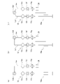
- FIG. 7 (a) is a schematic diagram showing a state in which the articulated arm according to the present embodiment is folded at a joint
- FIG. 7 (b) is a schematic diagram showing a state in which the articulated arm according to a modified example is folded.
- FIG. 7 (c) is a schematic view showing a state in which the articulated arm according to another modified example is folded.
- FIG. 1 is a perspective view of a work support robot according to the present embodiment.
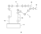
- FIG. 2 is a diagram showing the mechanism of the work support robot of FIG.
- FIG. 3 is a diagram showing a mechanism of a work support robot when a plurality of articulated arms are directed in the same direction.
- the work support robot 10 shown in FIG. 1 includes a plurality of articulated arms 12 and 14, an elevating unit 16 that elevates and elevates the plurality of articulated arms 12 and 14, respectively, and a main body unit 18 provided with the elevating unit 16.
- a moving mechanism 20 for moving the main body unit 18 to a predetermined position with respect to the target of work support is provided.
- the elevating unit 16 has a first elevating unit 16a for elevating and lowering the articulated arm 12 and a second elevating unit 16b for elevating and lowering the articulated arm 14.
- the articulated arm 12 has seven joints 12a to 12g from the side closer to the first elevating unit 16a.
- the articulated arm 14 has seven joints 14a to 14g from the side closer to the second elevating unit 16b.
- the joints 12a to 12g each have a rotation shaft 22a to 22g, and the joints 14a to 114g each have a rotation shaft 24a to 24g. That is, the articulated arm 12 has 8 degrees of freedom (7 or more degrees of freedom) including the degree of freedom of vertical movement by the first elevating unit 16a. Similarly, the articulated arm 14 has 8 degrees of freedom (7 or more degrees of freedom) including the degree of freedom of vertical movement by the second elevating unit 16b.
- the elevating unit 16 shifts the positions of the plurality of articulated arms 12 and 14 in the height direction.
- the articulated arms 12 and 14 can be oriented in the same direction without interference. Therefore, the movements and postures required for the plurality of articulated arms 12 and 14 can be realized in a small space.
- the articulated arm 12 moved above the articulated arm 14 by the first elevating unit 16a supports work while overlapping with the articulated arm 14 when viewed in the vertical direction. It is configured to be able to extend towards the subject.
- the area S obtained by projecting the articulated arm 12 and the articulated arm 14 onto the horizontal plane becomes small, and care is taken around the work support robot 10 without interfering with the articulated arms 12 and 14. It makes it easier for workers such as people and medical personnel to work.
- first elevating unit 16a and the second elevating unit 16b are provided side by side on the upper part of the main body unit 18 of the work support robot 10. As a result, the elevating unit 16 can be prevented from protruding to the side of the main body unit 18, so that the area occupied by the work support robot 10 can be reduced.
- the articulated arm 12 has a joint 12a closest to the first elevating unit 16a and a joint 12b next to the joint 12a.
- the joint 12a has a rotation shaft 22a along the vertical movement axis Za of the first elevating unit 16a.
- the rotation axis 22a along the axis Za is not only when the axis Za and the rotation axis 22a are parallel to each other, but also when the angle formed by the axis Za and the rotation axis 22a is in the range of 0 ⁇ 45 ° or 0 ⁇ . It may also include a range of 30 ° or a range of 0 ⁇ 15 °.
- the joint 12b has a rotation shaft 22b that intersects the rotation shaft 22a.
- the rotation axis 22b that intersects the rotation axis 22a is not only when the rotation axis 22a and the rotation axis 22b are orthogonal to each other, but also in a range where the angle formed by the rotation axis 22a and the rotation axis 22b is 90 ⁇ 45 °.
- the range of 90 ⁇ 30 ° or the range of 90 ⁇ 15 ° may be included.
- the work support robot 10 can be configured by the links La and Lb extending in the vertical direction from the first elevating unit 16a to the joints 12b, the joints 12b and the links La and Lb protrude to the side of the main body unit 18. The area occupied by the work support robot 10 can be reduced.
- the articulated arm 14 has a joint 14a closest to the second elevating unit 16b and a joint 14b next to the joint 14a.
- the joint 14a has a rotation shaft 24a along the vertical movement axis Zb of the second elevating unit 16b.
- the rotation axis 24a along the axis Zb is not only when the axis Zb and the rotation axis 24a are parallel to each other, but also when the angle formed by the axis Zb and the rotation axis 24a is in the range of 0 ⁇ 45 ° or 0 ⁇ . It may also include a range of 30 ° or a range of 0 ⁇ 15 °.
- the joint 14b has a rotation shaft 24b that intersects the rotation shaft 24a.
- the rotating shaft 24b that intersects the rotating shaft 24a is not only when the rotating shaft 24a and the rotating shaft 24b are orthogonal to each other, but also in a range where the angle formed by the rotating shaft 24a and the rotating shaft 24b is 90 ⁇ 45 °. Alternatively, the range of 90 ⁇ 30 ° or the range of 90 ⁇ 15 ° may be included.
- the work support robot 10 can be configured by the links L'a and L'b extending in the vertical direction from the second elevating unit 16b to the joints 14b, the joints 14b and the links L'a and L'b are the main bodies. The area occupied by the work support robot 10 can be reduced without protruding to the side of the unit 18.
- the articulated arm located above the articulated arm 12 and the articulated arm 14 can move 360 ° around the main body unit 18. Therefore, the work space in which the articulated arm can be arranged so as to reach a desired area is widened, and it becomes easy to arrange the work support robot 10 in a place where it does not easily interfere with the operator.
- the articulated arms 12 and 14 have a mounting portion 26 at the tip to which one can be selectively mounted from a plurality of types of end effectors used as surgical tools.
- Examples of the end effector used as a surgical tool include a forceps device and an endoscope.
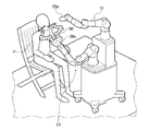
- FIG. 4 is a schematic diagram showing a state in which a patient lying on a bed is operated on by using a plurality of work support robots.
- FIG. 5 is a schematic diagram showing a state in which a patient lying on a bed is inspected using a work support robot.
- FIG. 6 is a schematic diagram showing a state in which a patient sitting on a chair is inspected using a work support robot.
- each work support robot 10a and 10b can bring a plurality of articulated arms 12 and 14 closer to each other from the same side of the patient P, which is the target of work support, instead of from both sides.
- the work support robots 10a and 10b each other based on various information such as wireless communication, GPS position information, position information of surrounding objects by radar, image data acquired by an image pickup means such as a camera, and the like. It may be configured so that the positional relationship can be grasped.
- the work support robots 10a and 10b can be placed at positions suitable for the patient P without interfering with each other. Further, the work support robots 10a and 10b can be arranged at positions that do not interfere with the doctor or the worker.
- a forceps device 28 and an endoscope are attached to the attachment portion 26 of each articulated arm shown in FIG.
- the mounting portion 26a of the articulated arm 12 may have a built-in camera for photographing the affected portion and the treated portion of the patient P. Further, a treatment tool 30 for inspecting the patient P is attached to the attachment portion 26b of the other articulated arm 14.
- FIG. 7 (a) is a schematic diagram showing a state in which the articulated arm according to the present embodiment is folded at a joint
- FIG. 7 (b) is a schematic diagram showing a state in which the articulated arm according to a modified example is folded.
- FIG. 7 (c) is a schematic view showing a state in which the articulated arm according to another modified example is folded.
- the link Le connecting the joint 12d and the joint 12e is L-shaped (see FIG. 1). Therefore, when the multi-joint arm 12 is folded at the joint 12d, the link from the joint 12a to the joint 12d and the link from the joint 12e to the joint 12g can be made substantially parallel.
- the link Ld connecting the joints 12c and the joints 12d is L-shaped. Therefore, when the multi-joint arm 12 is folded at the joint 12d, the link from the joint 12a to the joint 12c and the link from the joint 12d to the joint 12g can be made substantially parallel.
- the link Ld connecting the joint 12c and the joint 12d and the link Le connecting the joint 12d and the joint 12e are both U-shaped (V-shaped). Therefore, when the multi-joint arm 12 is folded at the joint 12d, the link from the joint 12a to the joint 12d and the link from the joint 12d to the joint 12g can be made substantially parallel.
- the present invention has been described above with reference to the above-described embodiment, the present invention is not limited to the above-described embodiment, and the present invention is not limited to the above-described embodiment, and the present invention may be a combination or a replacement of the configurations of the embodiments as appropriate. It is included in the present invention. Further, it is also possible to appropriately rearrange the combinations and the order of processing in the embodiment based on the knowledge of those skilled in the art, and to add modifications such as various design changes to the embodiments, and such modifications are added. The embodiments described above may also be included in the scope of the present invention.
- the present invention can be used for work support robots such as surgery, nursing care, manufacturing, and transportation.
Abstract
Un robot d'assistance au travail 10 comprend : une pluralité de bras multi-joints 12, 14; une unité d'élévation/abaissement qui élève/abaisse chaque bras de la pluralité de bras multi-joints 12, 14; et une unité de corps 18 sur laquelle l'unité d'élévation/abaissement est disposée. Les bras multi-joints 12, 14 ont au moins sept degrés de liberté, y compris des degrés de liberté de mouvement vers le haut/vers le bas par l'intermédiaire de l'unité d'élévation/abaissement 16.
Priority Applications (5)
| Application Number | Priority Date | Filing Date | Title |
|---|---|---|---|
| CN202080106119.0A CN116367968A (zh) | 2020-10-15 | 2020-10-15 | 作业辅助机器人 |
| EP20957704.8A EP4223459A4 (fr) | 2020-10-15 | 2020-10-15 | Robot d'assistance au travail |
| PCT/JP2020/038998 WO2022079875A1 (fr) | 2020-10-15 | 2020-10-15 | Robot d'assistance au travail |
| JP2022532649A JP7200458B2 (ja) | 2020-10-15 | 2020-10-15 | 作業支援ロボット |
| US18/300,054 US20230256590A1 (en) | 2020-10-15 | 2023-04-13 | Work assistance robot |
Applications Claiming Priority (1)
| Application Number | Priority Date | Filing Date | Title |
|---|---|---|---|
| PCT/JP2020/038998 WO2022079875A1 (fr) | 2020-10-15 | 2020-10-15 | Robot d'assistance au travail |
Related Child Applications (1)
| Application Number | Title | Priority Date | Filing Date |
|---|---|---|---|
| US18/300,054 Continuation US20230256590A1 (en) | 2020-10-15 | 2023-04-13 | Work assistance robot |
Publications (1)
| Publication Number | Publication Date |
|---|---|
| WO2022079875A1 true WO2022079875A1 (fr) | 2022-04-21 |
Family
ID=81208999
Family Applications (1)
| Application Number | Title | Priority Date | Filing Date |
|---|---|---|---|
| PCT/JP2020/038998 WO2022079875A1 (fr) | 2020-10-15 | 2020-10-15 | Robot d'assistance au travail |
Country Status (5)
| Country | Link |
|---|---|
| US (1) | US20230256590A1 (fr) |
| EP (1) | EP4223459A4 (fr) |
| JP (1) | JP7200458B2 (fr) |
| CN (1) | CN116367968A (fr) |
| WO (1) | WO2022079875A1 (fr) |
Citations (7)
| Publication number | Priority date | Publication date | Assignee | Title |
|---|---|---|---|---|
| JPH0870033A (ja) * | 1994-08-26 | 1996-03-12 | Kokusai Electric Co Ltd | 半導体製造装置のウェーハ移載機 |
| US20010013764A1 (en) * | 1998-08-04 | 2001-08-16 | Blumenkranz Steven J. | Manipulator positioning linkage for robotic surgery |
| JP2009525098A (ja) * | 2006-02-03 | 2009-07-09 | ザ ヨーロピアン アトミック エナジー コミュニティ(ユーラトム)、リプリゼンテッド バイ ザ ヨーロピアン コミッション | 最小侵襲医療手技を実行するためのロボット手術システム |
| JP2011206312A (ja) * | 2010-03-30 | 2011-10-20 | Terumo Corp | 医療用ロボットシステム |
| WO2017002142A1 (fr) | 2015-06-29 | 2017-01-05 | 川崎重工業株式会社 | Système de robot |
| CN109730778A (zh) * | 2019-03-20 | 2019-05-10 | 苏州康多机器人有限公司 | 一种双控制协同操作的腹腔镜手术机器人及系统 |
| JP2020065644A (ja) * | 2018-10-23 | 2020-04-30 | 株式会社A−Traction | 手術支援装置、その制御方法及びプログラム |
Family Cites Families (3)
| Publication number | Priority date | Publication date | Assignee | Title |
|---|---|---|---|---|
| JP6435400B2 (ja) | 2015-03-06 | 2018-12-05 | 株式会社日立製作所 | 作業ロボット及びグリッパ |
| DE102016004840A1 (de) * | 2016-04-24 | 2017-10-26 | Kastanienbaum GmbH | Mobiler Roboter |
| JP2022533297A (ja) | 2019-03-07 | 2022-07-22 | プロセプト バイオロボティクス コーポレイション | 組織切除および撮像のためのロボットアームおよび方法 |
-
2020
- 2020-10-15 JP JP2022532649A patent/JP7200458B2/ja active Active
- 2020-10-15 WO PCT/JP2020/038998 patent/WO2022079875A1/fr unknown
- 2020-10-15 EP EP20957704.8A patent/EP4223459A4/fr active Pending
- 2020-10-15 CN CN202080106119.0A patent/CN116367968A/zh active Pending
-
2023
- 2023-04-13 US US18/300,054 patent/US20230256590A1/en active Pending
Patent Citations (7)
| Publication number | Priority date | Publication date | Assignee | Title |
|---|---|---|---|---|
| JPH0870033A (ja) * | 1994-08-26 | 1996-03-12 | Kokusai Electric Co Ltd | 半導体製造装置のウェーハ移載機 |
| US20010013764A1 (en) * | 1998-08-04 | 2001-08-16 | Blumenkranz Steven J. | Manipulator positioning linkage for robotic surgery |
| JP2009525098A (ja) * | 2006-02-03 | 2009-07-09 | ザ ヨーロピアン アトミック エナジー コミュニティ(ユーラトム)、リプリゼンテッド バイ ザ ヨーロピアン コミッション | 最小侵襲医療手技を実行するためのロボット手術システム |
| JP2011206312A (ja) * | 2010-03-30 | 2011-10-20 | Terumo Corp | 医療用ロボットシステム |
| WO2017002142A1 (fr) | 2015-06-29 | 2017-01-05 | 川崎重工業株式会社 | Système de robot |
| JP2020065644A (ja) * | 2018-10-23 | 2020-04-30 | 株式会社A−Traction | 手術支援装置、その制御方法及びプログラム |
| CN109730778A (zh) * | 2019-03-20 | 2019-05-10 | 苏州康多机器人有限公司 | 一种双控制协同操作的腹腔镜手术机器人及系统 |
Non-Patent Citations (1)
| Title |
|---|
| See also references of EP4223459A4 |
Also Published As
| Publication number | Publication date |
|---|---|
| CN116367968A (zh) | 2023-06-30 |
| US20230256590A1 (en) | 2023-08-17 |
| JPWO2022079875A1 (fr) | 2022-04-21 |
| JP7200458B2 (ja) | 2023-01-10 |
| EP4223459A1 (fr) | 2023-08-09 |
| EP4223459A4 (fr) | 2023-11-22 |
Similar Documents
| Publication | Publication Date | Title |
|---|---|---|
| JP7273003B2 (ja) | ハードウェア拘束リモートセンタロボットマニピュレータのための冗長な軸及び自由度 | |
| JP6680862B2 (ja) | 外科用アーム | |
| JP7263441B2 (ja) | 手術器具マニピュレータの態様 | |
| US11267141B2 (en) | Articulation for surgical robot | |
| JP2018516656A (ja) | 外科用ロボットのリストにおけるトルクセンシング | |
| JP2017537663A (ja) | 一体化された手術台のシステム及び方法 | |
| BRPI1011053B1 (pt) | Sistema robótico para cirurgia laparoscópica | |
| KR102206647B1 (ko) | 로봇 암 구조물 및 이를 포함하는 수술 로봇의 매니퓰레이터 | |
| KR20180090331A (ko) | 외과수술 시스템 | |
| WO2022079875A1 (fr) | Robot d'assistance au travail | |
| Ai et al. | Design of a novel robotic system for minimally invasive surgery | |
| RU2753118C2 (ru) | Роботизированная система для удержания и перемещения хирургического инструмента при проведении лапароскопических операций | |
| KR20180090330A (ko) | 외과수술 시스템 |
Legal Events
| Date | Code | Title | Description |
|---|---|---|---|
| ENP | Entry into the national phase |
Ref document number: 2022532649 Country of ref document: JP Kind code of ref document: A |
|
| 121 | Ep: the epo has been informed by wipo that ep was designated in this application |
Ref document number: 20957704 Country of ref document: EP Kind code of ref document: A1 |
|
| ENP | Entry into the national phase |
Ref document number: 2020957704 Country of ref document: EP Effective date: 20230502 |
|
| NENP | Non-entry into the national phase |
Ref country code: DE |