EP3315072A1 - System and method for navigating a tomosynthesis stack using synthesized image data - Google Patents
System and method for navigating a tomosynthesis stack using synthesized image data Download PDFInfo
- Publication number
- EP3315072A1 EP3315072A1 EP17176956.5A EP17176956A EP3315072A1 EP 3315072 A1 EP3315072 A1 EP 3315072A1 EP 17176956 A EP17176956 A EP 17176956A EP 3315072 A1 EP3315072 A1 EP 3315072A1
- Authority
- EP
- European Patent Office
- Prior art keywords
- image
- images
- synthesized
- region
- tomosynthesis
- Prior art date
- Legal status (The legal status is an assumption and is not a legal conclusion. Google has not performed a legal analysis and makes no representation as to the accuracy of the status listed.)
- Granted
Links
- 238000000034 method Methods 0.000 title claims abstract description 76
- 210000000481 breast Anatomy 0.000 claims abstract description 87
- 238000012545 processing Methods 0.000 claims description 50
- 230000004044 response Effects 0.000 claims description 20
- 230000000694 effects Effects 0.000 claims description 6
- 210000001519 tissue Anatomy 0.000 description 49
- 208000004434 Calcinosis Diseases 0.000 description 32
- 230000008569 process Effects 0.000 description 24
- 238000009607 mammography Methods 0.000 description 21
- 230000002308 calcification Effects 0.000 description 19
- 238000010586 diagram Methods 0.000 description 12
- 238000012552 review Methods 0.000 description 12
- 238000003384 imaging method Methods 0.000 description 11
- 238000012800 visualization Methods 0.000 description 8
- 238000005516 engineering process Methods 0.000 description 6
- 238000003745 diagnosis Methods 0.000 description 5
- 238000001514 detection method Methods 0.000 description 4
- 235000019580 granularity Nutrition 0.000 description 4
- 238000012216 screening Methods 0.000 description 4
- 206010006187 Breast cancer Diseases 0.000 description 3
- 208000026310 Breast neoplasm Diseases 0.000 description 3
- 230000005856 abnormality Effects 0.000 description 3
- 239000002131 composite material Substances 0.000 description 3
- 238000001914 filtration Methods 0.000 description 3
- 238000013507 mapping Methods 0.000 description 3
- 230000007246 mechanism Effects 0.000 description 3
- 230000008901 benefit Effects 0.000 description 2
- 210000004204 blood vessel Anatomy 0.000 description 2
- 238000004891 communication Methods 0.000 description 2
- 238000013213 extrapolation Methods 0.000 description 2
- 230000000977 initiatory effect Effects 0.000 description 2
- 230000003902 lesion Effects 0.000 description 2
- 230000002194 synthesizing effect Effects 0.000 description 2
- 206010028980 Neoplasm Diseases 0.000 description 1
- 241000577979 Peromyscus spicilegus Species 0.000 description 1
- 230000002159 abnormal effect Effects 0.000 description 1
- 230000009471 action Effects 0.000 description 1
- 230000003213 activating effect Effects 0.000 description 1
- 230000004913 activation Effects 0.000 description 1
- 230000005540 biological transmission Effects 0.000 description 1
- 230000006835 compression Effects 0.000 description 1
- 238000007906 compression Methods 0.000 description 1
- 238000010276 construction Methods 0.000 description 1
- 239000002872 contrast media Substances 0.000 description 1
- 208000031513 cyst Diseases 0.000 description 1
- 238000011161 development Methods 0.000 description 1
- 238000006073 displacement reaction Methods 0.000 description 1
- 238000011156 evaluation Methods 0.000 description 1
- 238000002955 isolation Methods 0.000 description 1
- 210000001165 lymph node Anatomy 0.000 description 1
- 210000002445 nipple Anatomy 0.000 description 1
- 238000004513 sizing Methods 0.000 description 1
- 238000012358 sourcing Methods 0.000 description 1
- 230000007704 transition Effects 0.000 description 1
- 230000000007 visual effect Effects 0.000 description 1
Images


Classifications
-
- G—PHYSICS
- G06—COMPUTING; CALCULATING OR COUNTING
- G06T—IMAGE DATA PROCESSING OR GENERATION, IN GENERAL
- G06T19/00—Manipulating 3D models or images for computer graphics
- G06T19/003—Navigation within 3D models or images
-
- A—HUMAN NECESSITIES
- A61—MEDICAL OR VETERINARY SCIENCE; HYGIENE
- A61B—DIAGNOSIS; SURGERY; IDENTIFICATION
- A61B6/00—Apparatus for radiation diagnosis, e.g. combined with radiation therapy equipment
- A61B6/02—Devices for diagnosis sequentially in different planes; Stereoscopic radiation diagnosis
- A61B6/025—Tomosynthesis
-
- A—HUMAN NECESSITIES
- A61—MEDICAL OR VETERINARY SCIENCE; HYGIENE
- A61B—DIAGNOSIS; SURGERY; IDENTIFICATION
- A61B6/00—Apparatus for radiation diagnosis, e.g. combined with radiation therapy equipment
- A61B6/46—Apparatus for radiation diagnosis, e.g. combined with radiation therapy equipment with special arrangements for interfacing with the operator or the patient
- A61B6/461—Displaying means of special interest
- A61B6/466—Displaying means of special interest adapted to display 3D data
-
- A—HUMAN NECESSITIES
- A61—MEDICAL OR VETERINARY SCIENCE; HYGIENE
- A61B—DIAGNOSIS; SURGERY; IDENTIFICATION
- A61B6/00—Apparatus for radiation diagnosis, e.g. combined with radiation therapy equipment
- A61B6/50—Clinical applications
- A61B6/502—Clinical applications involving diagnosis of breast, i.e. mammography
-
- G—PHYSICS
- G06—COMPUTING; CALCULATING OR COUNTING
- G06F—ELECTRIC DIGITAL DATA PROCESSING
- G06F3/00—Input arrangements for transferring data to be processed into a form capable of being handled by the computer; Output arrangements for transferring data from processing unit to output unit, e.g. interface arrangements
- G06F3/01—Input arrangements or combined input and output arrangements for interaction between user and computer
- G06F3/048—Interaction techniques based on graphical user interfaces [GUI]
- G06F3/0481—Interaction techniques based on graphical user interfaces [GUI] based on specific properties of the displayed interaction object or a metaphor-based environment, e.g. interaction with desktop elements like windows or icons, or assisted by a cursor's changing behaviour or appearance
- G06F3/04815—Interaction with a metaphor-based environment or interaction object displayed as three-dimensional, e.g. changing the user viewpoint with respect to the environment or object
-
- G—PHYSICS
- G06—COMPUTING; CALCULATING OR COUNTING
- G06F—ELECTRIC DIGITAL DATA PROCESSING
- G06F3/00—Input arrangements for transferring data to be processed into a form capable of being handled by the computer; Output arrangements for transferring data from processing unit to output unit, e.g. interface arrangements
- G06F3/01—Input arrangements or combined input and output arrangements for interaction between user and computer
- G06F3/048—Interaction techniques based on graphical user interfaces [GUI]
- G06F3/0484—Interaction techniques based on graphical user interfaces [GUI] for the control of specific functions or operations, e.g. selecting or manipulating an object, an image or a displayed text element, setting a parameter value or selecting a range
- G06F3/04842—Selection of displayed objects or displayed text elements
-
- G—PHYSICS
- G06—COMPUTING; CALCULATING OR COUNTING
- G06T—IMAGE DATA PROCESSING OR GENERATION, IN GENERAL
- G06T7/00—Image analysis
- G06T7/0002—Inspection of images, e.g. flaw detection
- G06T7/0012—Biomedical image inspection
-
- G—PHYSICS
- G06—COMPUTING; CALCULATING OR COUNTING
- G06T—IMAGE DATA PROCESSING OR GENERATION, IN GENERAL
- G06T2207/00—Indexing scheme for image analysis or image enhancement
- G06T2207/30—Subject of image; Context of image processing
- G06T2207/30004—Biomedical image processing
- G06T2207/30068—Mammography; Breast
Landscapes
- Engineering & Computer Science (AREA)
- Health & Medical Sciences (AREA)
- Life Sciences & Earth Sciences (AREA)
- Medical Informatics (AREA)
- Physics & Mathematics (AREA)
- Radiology & Medical Imaging (AREA)
- Theoretical Computer Science (AREA)
- General Health & Medical Sciences (AREA)
- Nuclear Medicine, Radiotherapy & Molecular Imaging (AREA)
- Animal Behavior & Ethology (AREA)
- General Engineering & Computer Science (AREA)
- Optics & Photonics (AREA)
- Biomedical Technology (AREA)
- Heart & Thoracic Surgery (AREA)
- Molecular Biology (AREA)
- Surgery (AREA)
- High Energy & Nuclear Physics (AREA)
- Biophysics (AREA)
- Public Health (AREA)
- Veterinary Medicine (AREA)
- Pathology (AREA)
- General Physics & Mathematics (AREA)
- Human Computer Interaction (AREA)
- Software Systems (AREA)
- Dentistry (AREA)
- Oral & Maxillofacial Surgery (AREA)
- Remote Sensing (AREA)
- Computer Graphics (AREA)
- Computer Hardware Design (AREA)
- Radar, Positioning & Navigation (AREA)
- Quality & Reliability (AREA)
- Computer Vision & Pattern Recognition (AREA)
- Apparatus For Radiation Diagnosis (AREA)
Abstract
Description
- This application claims the benefit of priority under 35 U.S.C. §119 to
U.S. Provisional Patent Application No. 61/597,958, filed February 13, 2012 - The inventions disclosed herein pertain to breast imaging using tomosynthesis, and more specifically to a system and method for guiding the navigation of a tomosynthesis data set, which employs a synthesized 2D image that is obtained by importing relevant data from the tomosynthesis data set into the synthesized image, and then using the 2D image to navigate the tomosynthesis data.
- Mammography has long been used to screen for breast cancer and other abnormalities. Traditionally, mammograms have been formed on x-ray film. More recently, flat panel digital imagers have been introduced that acquire a mammogram in digital form, and thereby facilitate analysis and storage of the acquired images, and provide other benefits as well. Further, substantial attention and technological development has been dedicated towards obtaining three-dimensional images of the breast, using methods such as breast tomosynthesis. In contrast to the 2D images generated by legacy mammography systems, breast tomosynthesis systems construct a 3D image volume from a series of 2D projection images, each projection image obtained at a different angular displacement of an x-ray source relative to the image detector as the x-ray source is scanned over the detector. The constructed 3D image volume is typically presented as a plurality of slices of image data, the slices being geometrically reconstructed on planes parallel to the imaging detector. The reconstructed tomosynthesis slices reduce or eliminate the problems caused by tissue overlap and structure noise present in single slice, two-dimensional mammography imaging, by permitting a medical professional (e.g., a radiologist) to scroll through the image slices to view underlying structures.
- Tomosynthesis systems have recently been developed for breast cancer screening and diagnosis. In particular, Hologic, Inc. (www.hologic.com), has developed a fused, multimode mammography/tomosynthesis system that acquires one or both types of mammogram and tomosynthesis images, either while the breast remains immobilized or in different compressions of the breast. Other companies have proposed the introduction of systems which are dedicated to tomosynthesis imaging; i.e., which do not include the ability to also acquire a mammogram.
- However, systems restricted to tomosynthesis acquisition and image display may present an obstacle to acceptance of the tomosynthesis imaging technology, as medical professionals have grown accustomed to screening and analysis of conventional 2D mammogram images. In particular, mammograms provide good visualization of micro-calcifications, and can offer higher spatial resolution when compared with tomosynthesis images. While tomosynthesis images provided by dedicated breast tomosynthesis systems have other desirable characteristics, e.g., better isolation and visualization of structures in the breast, such systems do not leverage the existing interpretation expertise of medical professionals.
- Examples of systems and methods that leverage existing medical expertise in order to facilitate the transition to tomosynthesis technology are described in
U.S. Patent No. 7,760,924 , which is hereby incorporated by reference in its entirety. In particular,U.S. Patent No. 7,760,924 describes a method of generating a synthesized 2D image, which may be displayed along with tomosynthesis projection or reconstructed images, in order to assist in screening and diagnosis. - According to one aspect of the inventions disclosed and described herein, a system and method for processing, displaying and navigating breast tissue information is provided, wherein the system is configured for, and the method includes: (i) obtaining a plurality of 2D and/or 3D images of a patient's breast; (ii) generating a synthesized 2D image of the patient's breast from the obtained 2D and/or 3D images of the plurality; (iii) displaying the synthesized 2D image; (iv) receiving a user command, or otherwise detecting through a user interface, a user selection or other indication of an object or region in the synthesized 2D image; and (v) displaying at least a portion of one or more images from the plurality, including a source image and/or most similar representation of the user selected or indicated object or region.
- Additionally and/or alternatively, the system may be configured for, and the method may include, concurrently displaying a respective source image and/or most similar representation of a tissue structure or region that corresponds to a given location of a user movable input device in the displayed synthesized 2D image. While various image processing techniques may be employed for providing the this navigational functionality, in a preferred embodiment, the system is preferably configured for, and the method further includes, generating an index map comprising identifying information of selected images of the plurality of 2D and/or 3D images that are source images or that otherwise contain a most similar representation of regions and/or objects displayed in the synthesized 2D image. The index map can thereafter be used by the system for to greatly reduce the time needed to navigate through the images, e.g., a tomosynthesis volume stack of the breast image volume.
- The plurality of source images may include one or more of tomosynthesis projection images, reconstructed tomosynthesis slices, mammograms, contrast enhanced mammograms, and synthesized two dimensional images. In various embodiments, the plurality of 2D and/or 3D images of a patient's breast are acquired or synthesized X,Y coordinate slices at differing z axis locations of the breast, the images having one or more corresponding X,Y coordinate locations. In one embodiment, generating the synthesized 2D image includes constructing a merged image by importing one or more objects and/or regions from the images of the plurality into the merged image, wherein an image from which an object or region is imported into the merged image comprises a source image for that object or region. In such embodiment, objects or regions are preferably imported into the merged image at X,Y coordinate locations corresponding to the X,Y coordinate locations of the respective objects or regions in their source image. Further to such embodiment, each image of the plurality of 2D and/or 3D images preferably contains one or more regions defined by their X,Y coordinate locations that are common for all images of the plurality, wherein one of each said common region is imported from the plurality of images into the merged image based upon a comparison of one or more system and/or user defined attributes of the respective common region of each image.
- In a preferred variation of this embodiment, an identified object or region of interest in a given image has priority for importation into the merged image over any other identified objects or regions of interest having the same or overlapping X,Y coordinate locations in other image slices based upon a predefined priority scheme, e.g., to reflect the relative clinical importance of the various possible tissue structures. The preferred attributes may include attributes indicative of regions of interest, such as cancers, or alternatively such as more accurate representation of breast density or breast anatomy, i.e., truthful breast-border/nipple appearance, or presence of a contrast agent in the case of contrast enhanced mammography. In general, any attribute capable to delivering a high/better-quality image can be relevant.
- In various embodiments, an object or region may be automatically highlighted in the synthesized 2D image and/or displayed at least portion of the one or more images from the plurality. Additionally and/or alternatively, an object or region in the synthesized 2D image and/or displayed at least portion of the one or more images from the plurality may be highlighted in response to a further received user command or to certain user activity detected through the user interface. By way of non-limiting example, an object or region may is highlighted by a contour line representing a boundary of the highlighted object or region. Preferably, the object or region is highlighted in a manner indicating that the highlighted object or region is or contains a specified type of tissue structure.
- According to another aspect of the inventions disclosed and described herein, a system and method for processing, displaying and navigating breast tissue information is provided, wherein the system is configured for, and the method includes: (i) obtaining a plurality of tomosynthesis images comprising volumetric image data of a patient's breast; (ii) generating a synthesized 2D image of the patient's breast at least in part from the tomosynthesis images; (iii) displaying the synthesized 2D image; (iv) receiving a user command, or otherwise detecting through a user interface, a user selection or other indication of an object or region in the synthesized 2D image; and (v) displaying at least a portion of one or more tomosynthesis images from the plurality, including a source image and/or most similar representation of the user selected or indicated object or region. Again, while various image processing techniques may be employed for providing the this navigational functionality, in a preferred embodiment, the system is preferably configured for, and the method further includes, generating an index map that includes identifying information of selected tomosynthesis images of the plurality that are source images or that otherwise contain a most similar representation of regions and/or objects in the synthesized 2D image.
- These and other aspects and embodiments of the disclosed inventions are described in more detail below, in conjunction with the accompanying figures.
-
-
FIG. 1 is a block diagram illustrating the flow of data through a system that includes a combination mammography/tomosynthesis acquisition system and/or a tomosynthesis-only acquisition system to acquire tomosynthesis and/or mammography (including contrast mammography) images of a patient's breast, and further includes one or more processors that implement the image merge technology of the presently disclosed inventions for providing a two dimensional synthesized image by importing the most relevant data from the acquired 2D and/or 3D source images into a single merged 2D image for display to a medical professional; -
FIG. 2 is a diagram illustrating the data flow of a series of tomosynthesis slices and a synthesized 2D mammogram through the image merge technology of the presently disclosed inventions to generate a merged image and a corresponding merge (or "guidance") map; -
FIG. 3 depicts one embodiment of a displayed merged image, wherein certain region boundaries are dynamically identified during merge image build; -
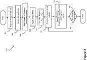
FIG. 4 is a flow diagram illustrating exemplary steps performed during an image merge process according to one embodiment of the presently disclosed inventions; -
FIGS. 5A and 5B illustrate one embodiment of a display of a merged image, and a resultant display of a source image in response to selection of a region in the merged image by a user; -
FIG. 6 is a flow diagram illustrating an exemplary process for retrieving and presenting a reconstructed tomosynthesis image slice in response to user-selection of an object of interest in a synthesized 2D image, according to one embodiment of the presently disclosed inventions; -
FIG. 7 is a flow diagram illustrating another exemplary process for retrieving and presenting a reconstructed tomosynthesis image slice in response to user-selection of an object of interest in a synthesized 2D image, according to another embodiment of the presently disclosed inventions; -
FIG. 8 is a flow diagram illustrating a process for constructing a composite index map of a synthesized 2D image to a corresponding reconstructed tomosynthesis image stack, according to still another embodiment of the presently disclosed inventions; -
FIG. 9 depicts an exemplary user interface, including a left-hand side monitor displaying a synthesized 2D image of a patient's breast, including a highlighted tissue structure, wherein the highlighting is in the form of a contour line that represents a boundary of the highlighted tissue structure, and a right-hand side monitor displaying the tomosynthesis image from which the highlighted tissue structure was imported into the 2D image, or which otherwise provides a best view of the highlighted tissue structure; -
FIG. 10 depicts the user interface ofFIG. 9 , again displaying a synthesized 2D image of a patient's breast including a highlighted spiculated mass in the left-hand monitor, and a right-hand side monitor displaying the tomosynthesis image from which the depicted spiculated mass was imported into the 2D image, or which otherwise provides a best view of the spiculated mass; and -
FIG. 11 depicts the user interface ofFIG. 10 , including the same breast image displayed in the left-hand side monitor, but now highlighting a region containing micro-calcifications, with the right-hand side monitor displaying the tomosynthesis image from which the highlighted region containing the micro-calcifications was imported into the 2D image, or which otherwise provides a best view of the micro-calcifications. - In describing the depicted embodiments of the disclosed inventions illustrated in the accompanying figures, specific terminology is employed for the sake of clarity and ease of description. However, the disclosure of this patent specification is not intended to be limited to the specific terminology so selected, and it is to be understood that each specific element includes all technical equivalents that operate in a similar manner. It is to be further understood that the various elements and/or features of different illustrative embodiments may be combined with each other and/or substituted for each other wherever possible within the scope of this disclosure and the appended claims.
- The following abbreviations shall have the following definitions throughout this patent specification:
- Mp refers to a conventional mammogram or contrast enhanced mammogram, which are two-dimensional (2D) projection images of a breast, and encompasses both a digital image as acquired by a flat panel detector or another imaging device, and the image after conventional processing to prepare it for display and/or storage or other use.
- Tp refers to an image that is similarly two-dimensional (2D), but is acquired at a respective tomosynthesis angle between the breast and the origin of the imaging x rays (typically the focal spot of an x-ray tube), and encompasses the image as acquired, as well as the image data after being processed for display and/or storage or other use.
- Tr refers to an image that is reconstructed from tomosynthesis projection images Tp, for example, in the manner described in one or more of
U.S. Patent Application Publication No. 2010/0135558 , andU.S. Patent Nos. 7,760,924 ,7,606,801 , and7,577,282 , the disclosures of which are fully incorporated by reference herein in their entirety, wherein a Tr image represents a slice of the breast as it would appear in a projection x ray image of that slice at any desired angle, not only at an angle used for acquiring Tp or Mp images. - Ms refers to synthesized 2D images, which simulate mammography images, such as a craniocaudal (CC) or mediolateral oblique (MLO) images, and are constructed using tomosynthesis projection images Tp, tomosynthesis reconstructed images Tr, or a combination thereof. Examples of methods that may be used to generate Ms images are described in the above-incorporated
U.S. Patent Application Publication No. 2010/0135558 , andU.S. Patent No. 7,760,924 . - IMERGE refers to a 2D image constructed by importing into a single image one or more objects and/or regions from any two or more of Mp, Ms, Tp or Tr images of a patient's breast, wherein an image from which an object or region is imported into the merged image comprises a source image for that object or region, and wherein objects or regions are imported into the merged image at X,Y coordinate locations corresponding to the X,Y coordinate locations of the objects or regions in their respective source image
- The terms IMERGE, Tp, Tr, Ms and Mp each encompasses information, in whatever form, that is sufficient to describe the respective image for display, further processing, or storage. The respective IMERGE, Mp, Ms. Tp and Tr images are typically provided in digital form prior to being displayed, with each image being defined by information that identifies the properties of each pixel in a two-dimensional array of pixels. The pixel values typically relate to respective measured, estimated, or computed responses to x rays of corresponding volumes in the breast, i.e., voxels or columns of tissue. In a preferred embodiment, the geometry of the tomosynthesis images (Tr and Tp), mammography images (Ms and Mp) and the merged image IMERGE are matched to a common coordinate system, as described in
U.S. Patent No. 7,702,142 , the disclosure of which is hereby incorporated by reference in its entirety. Unless otherwise specified, such coordinate system matching is assumed to be implemented with respect to the embodiments described in the ensuing detailed description of this patent specification. -
FIG. 1 illustrates the flow of data in an exemplary image generation and display system, which incorporates the merged image generation and display technology and features of the presently disclosed inventions. It should be understood that, whileFIG. 1 illustrates a particular embodiment of a flow diagram with certain processes taking place in a particular serial order or in parallel, various other embodiments of the presently disclosed inventions are not limited to the performance of the image processing steps in any particular order, unless so specified. - More particularly, the image generation and display system includes an
image acquisition system 1 that acquires tomosynthesis image data for generating Tp images of a patient's breasts, using the respective three dimensional and/or tomosynthesis acquisition methods of any of the currently available systems. If the acquisition system is a combined tomosynthesis/mammography system, Mp images may also be generated. Some dedicated tomosynthesis systems or combined tomosynthesis/ mammography systems may be adapted to accept and store legacy mammogram images, (indicated by a dashed line and legend Mplegacy inFIG. 1 ) in a astorage device 2, which is preferably a DICOM-compliant Picture Archiving and Communication System (PACS) storage device. Following acquisition, the tomosynthesis projection images Tp may also be transmitted to the storage device 2 (as shown inFIG. 1 ). - The Tp images are transmitted from either the
acquisition system 1, or from thestorage device 2, or both, to a computer system configured as areconstruction engine 3 that reconstructs the Tp images into reconstructed image "slabs" Tr, representing breast slices of selected thickness and at selected orientations, as disclosed in the above-incorporated patents and application publication. The imaging anddisplay system 1 further includes a 2D synthesizer that operates substantially in parallel with the reconstruction engine for generating 2D images that simulate mammograms taken at any orientation (e.g., CC or MLO) using a combination of one or more Tp and/or Tr images. The synthesized 2D images may be generated dynamically prior to display (as shown inFIG. 1 ) or may be stored instorage system 2 for later use. The synthesized 2D images are interchangeably referenced as T2d and Ms. Thereconstruction engine display system 5 via a fast transmission link. The originally acquired Mp and/or Tp images may also be forwarded to thedisplay system 5 for concurrent or toggled viewing with the respective Tr and/or Ms images by a medical professional. -
Mode filters filters FIG. 1 , thefilters - According to one aspect of the disclosed inventions, and as described in greater detail herein, the
system 1 includes animage merge processor 6 that merges relevant image data obtained from a set of available source and synthesized images of a patient's breast to provide a merged 2D image IMERGE for display. The set of available images used to generate the merged image IMERGE may include filtered and/or unfiltered Ms, Mp, Tr and/or Tp images. WhileFIG. 1 depicts all these types of images being input into theimage merge processor 6, it is also envisioned within the scope of the disclosed inventions that the merged image may be manually configurable. For example, a user interface or preset configuration may be provided and configured to allow a user to select a particular group of two or more images or image types for generating a synthesized 2D image IMERGE for display. - By way of illustration, a medical professional, such as a radiologist, may wish to merge two or more reconstructed tomosynthesis slices (or slabs) in order to provide a merged image showing the most readily discerned structures in the collective tomosynthesis image data in a displayed synthesized 2D image, which essentially maps the tomosynthesis slices (or slabs) at a pixel wise granularity. Additionally or alternatively, the radiologist may combine a 2D mammogram image, whether Mp or Ms, with a 3D projection, or with selected reconstructed images, in order to obtain a customized merged image that highlights both calcifications and various tissue structures in the breast. Filters applied to each type of image can further highlight the types of structures or features in the merged image that are generally most prevalent or most readily discerned in the respective source image type. Thus, one type of filter may be applied to mammography images to highlight calcifications, while a different filter may be applied to tomosynthesis slices to highlight masses, allowing both the highlighted calcifications and highlighted tissue masses to be displayed in the single merged image. Filters may also provide the merged image with a desired look and feel; i.e., to make the merged image appear more like a tomosynthesis or mammography image.
- The
display system 5 may be part of a standard acquisition workstation (e.g., of acquisition system 1), or of a standard (multi-display) review station that is physically remote from theacquisition system 1. In some embodiments, a display connected via a communication network may be used, for example, a display of a personal computer or of a so-called tablet, smart phone or other hand-held device. In any event, thedisplay 5 of the system is preferably able to display IMERGE, Ms, Mp and Tr (and/or Tp) images concurrently, e.g., in separate side-by-side monitors of a review workstation, although the invention may still be implemented with a single display monitor, by toggling between images. - To facilitate the detection/diagnosis process, Tr slices are preferably reconstructed all to the same size for display, which can be the same as the size of an Mp or Ms image of the breast, or they can be initially reconstructed to sizes determined by the fan shape of the x ray beam used in the acquisition, and then later converted to that same size by appropriate interpolation and/or extrapolation. In this manner, images of different types and from different sources can be displayed in desirable size and resolution. For example, an image can be displayed in (1) Fit To View Port mode, in which the size of the displayed image size is maximized such that the entire imaged breast tissue is visible, (2) True Size mode, in which a display pixel on the screen corresponds to a pixel of the image, or (3) Right Size mode, in which the size of a displayed image is adjusted so that it matches that of another image being concurrently displayed, or with which the displayed image is, or can be, toggled.
- For example, if two images of the same breast are taken and are not the same size, or do not have the same resolution, provisions may be made to automatically or user-selectively increase or reduce the magnification (i.e., "zoom in" or "zoom out") of one or both images, such that they appear to be the same size when they are concurrently displayed, or as a user toggles between the images. Known interpolation, extrapolation and/or weighting techniques can be used to accomplish the re-sizing process, and known image processing technology can also be used to make other characteristics of the displayed images similar in a way that facilitates detection/diagnosis. When viewing such resized images, according to one embodiment of the disclosed inventions, the merged image IMERGE is automatically resized, accordingly.
- Thus, the
system 1, which is described as for purposes of illustration and not limitation in this patent specification, is capable of receiving and displaying selectively tomosynthesis projection images Tp, tomosynthesis reconstruction images Tr, a synthesized mammogram image Ms, and/or mammogram (including contrast mammogram) images Mp, or any one or sub combination of these image types. Thesystem 1 employs software to convert (i.e., reconstruct) tomosynthesis images Tp into images Tr, software for synthesizing mammogram images Ms, and software for merging a set of images to provide a merged image that displays, for every region of the merged image, the most relevant feature in that region among all images in the source image set. For the purpose of this patent specification, an object of interest or feature in a source image may be considered a 'most relevant' feature for inclusion in the merged image based upon the application of one or more CAD algorithms to the collective source images, wherein the CAD algorithms assign numerical values, weights or thresholds, to pixels or regions of the respective source images based upon identified/detected objects and features of interest within the respective region or between features or, in instances when the merged image is generated directly from the synthesized image without CAD assistance, simply the pixel value, weight or other threshold associated with a pixel or region of the image. The objects and features of interest may include, for example, spiculated lesions, calcifications, and the like. Various systems and methods are currently well known for computerized detection of abnormalities in radiographic images, such as those disclosed by Giger et al. in RadioGraphics, May 1993, pp. 647-656; Giger et al. in Proceedings of SPIE, Vol. 1445 (1991), pp. 101-103;U.S. Patent Nos. 4,907,156 ,5,133,020 ,5,343,390 , and5,491,627 , each of which being hereby incorporated by reference in its entirety. -
FIG. 2 is a diagram which pictorially illustrates the merging of image data from a tomosynthesis reconstruction image data set Tr, comprising tomosynthesis slices 10A to 10N, with image data from amammogram 20, in this case a synthesized mammogram Ms. For ease of description, filters are not shown in this example. The tomosynthesis image data set Tr and synthesized mammogram Ms are forwarded to the region compare andimage merge processor 6, which evaluates each of the source images for which a merged image is to be generated (i.e., whether automatically, or based on a specific user commend) in order to (1) identify the objects and features of interest in each image for those that may be considered a 'most relevant' feature for possible inclusion in the merged image based upon the application of one or more CAD algorithms (as described above), (2) identifies respective pixel regions in the images that contain the identified features, and (3) thereafter compares the images on a region by region basis, searching for that image with the most desirable display data for each respective region. - As discussed above, the image with the most desirable display data may be an image with a highest pixel value, a lowest pixel value, or which has been assigned a threshold value or weight based on the application of a CAD algorithm to the image. When the image with the most desirable display data for that region is identified, the pixels of that region are copied over to the corresponding region of the merged image. For example, as shown in
FIG. 2 , region 36M from image Ms is written to region 361.Region 35 oftomosynthesis slice 10A is copied to region 351 of the merged image. Although the regions ofFIG. 2 are shown as pre-defined grid regions, it is not necessary that regions be pre-defined in this manner. Rather, according to one aspect of the disclosed inventions, the boundaries of the regions may be dynamically identified during the region compare and image generation process by performing comparisons at pixel or multi-pixel granularities. By way of illustration,FIG. 3 illustrates amerged image 50, which has been constructed via the combinations of numerous regions of different source images, at arbitrary region boundaries, for example, which may be identified according to the detection of particular features within the respective source images. -
FIG. 4 is a flow diagram provided to illustrate exemplary steps that may be performed in an image merge process carried out in accordance with one embodiment of the disclosed inventions. Atstep 62, an image data set is acquired. The image data set may be acquired by a tomosynthesis acquisition system, a combination tomosynthesis/mammography system, or by retrieving pre-existing image data from a storage device, whether locally or remotely located relative to an image display device. Atstep 64, a user may optionally select a merge mode, wherein the user may designate (1) which images are to be used for the source image set to generate the merged image, (2) whether to highlight certain features in the merged image, such as calcifications, spiculated lesions or masses, and (3) whether to display the image as a lower resolution tomosynthesis image, etc. Atstep 66, the images that are to be merged to generate the merged image are mapped to a common coordinate system, for example, as described in the above-incorporatedU.S. Patent No. 7,702,142 . Other methods of matching images of different coordinate systems may alternatively be used. Atstep 72, the process of comparing regions among the different images begins. Atstep 74, each IMERGE region is populated with the pixels of the region of an image from the source image set having the most desirable pixels, value, or pattern. The process of populating regions continues until it is determined, atstep 76, that all regions have been evaluated, at which point the merged image is ready for display. - Once the merged image is generated, it may be used to assist in the navigation through a tomosynthesis image data stack from which the merge image was generated. Such navigation is a two-step process comprising selection of various objects of interest, and display of corresponding tomosynthesis images that are the source of such objects of interest in the merged image. By way of example,
FIG. 5A and Fig. 5B illustrate two views of adisplay 80. The first view ofdisplay 80 shown inFIG. 5A illustrates amerged image 82, having regions sourced by different ones of an acquired or synthesized image set.FIG. 5B illustrates a particular feature enabled by the presently disclosed inventions, whereby a user may select a region orarea 83 within themerged image 82, and the resultingimage source 84 for that area is presented to the user. - The presently disclosed inventions envision many different mechanisms for selection of the objects of interest and corresponding display of the respective source images corresponding; although it is to be understood that the disclosed inventions are not limited to those described herein. For example, the selection of a region or area within the merged image may include a selection of a CAD mark, or alternatively a selection of a particular feature of interest to the reviewer. Although in both instances the most relevant slices are made available to the user, the mechanics behind the processes differ. One such preferred mechanism is illustrated in
FIG. 2 . As the regions of the merged image are populated, a merge (or "guidance")map 40 is also constructed. The merge map stores, for each region of the merged image, an identifier of the image from which the region is sourced. Therefore, as shown inFIG. 2 , the Ms identifier is stored in region 36, while the 10A TR slice identifier is stored inregion 35. As will be described in more detail herein, the merged map may be used during the display of the merged image to permit fast viewing of the respective source image(s) for user-selected regions or objects of interest. - Selection using CAD marks:
- In addition or alternatively to use of a merge/guidance map, if the merged image is presented with a CAD overlay, the CAD overlay may include either CAD marks derived from 3D data, or CAD marks derived from 2D data (if the system has the ability to obtain 2D data). CAD marks derived from 3D data generally include, as part of the data object associated with the mark, identifiers of one or more slices which contributed to the generation of the 3D mark. When the merged image is overlaid with 3D CAD data, selection of the CAD mark results in the retrieval of the series of slices that contributed to the mark. In one embodiment, the central image slice is displayed; in alternate embodiments, the image slice having the highest weight is displayed; and in a still further alternate embodiment, the image slice having the least visual noise (i.e., the clearest image) is displayed.
- Selection by objects of interest:
- As an alternate to selecting by CAD marks, a mechanism is provided for allowing a user to select any object on a merged image, whether it is a CAD mark, or a feature of interest, such as any abnormality or irregularity in the image. In one embodiment, the user or system may select a region, using for example a mouse click for a single pixel area, or a click and drag action to select a larger region. Alternatively, the user may be provided with a selection of graphical frames of various or variable sizes, and have the ability to move the frame to different locations within the merged image to select areas when it is desired to view additional tomosynthesis image slices. In response to such a selection, the particular image slice for initial display may be selected in a variety of ways.
- For example, an image slice could be selected based on the weighting of its associated pixel within the selected region. Or a particular image slice may be selected because a particular feature which is selected, or which is near a pixel or region that is selected, is best viewed in the selected image slice, e.g., provides the clearest view of that region. Thus, the identification of a particular image slice that is most relevant to a selected pixel or region may utilize pixel information that surrounds the selected object, for example, using region growing techniques known to those in the art. Thus, pixels that neighbor the selected pixel or region are included in the evaluation for relevant slices if the pixels have a characteristic that satisfies a certain threshold established by the user; for example, including but not limited to the pixels having a particular weight, or being arranged in a particular pattern, etc.
- Alternatively, a group of image slices may be selected, e.g., a successive order of image slices, with a central slice or most heavily weighted slice being first presented. As described above, alternatively the image slice within the group having the least noise, i.e., the clearest slice, may be provided. In addition, the selection of an image slice for presentation may also take into account a desired visualization mode. Thus, if the user-specified purpose is to visualize calcifications, an image slice having calcification features may be presented ahead of another slice within the group having a lesser calcification characteristic.
- It will be appreciated that the disclosed and described systems and methods in this patent specification are designed to condense the image information made available from a tomosynthesis reconstruction volume (or "stack") containing a patient's 3D breast image data down to a single, synthesized 2D image, similar to a conventional 2D mammographic image. By reviewing this synthesized 2D image concurrently with the 3D tomosynthesis stack, it is possible to provide a much more efficient and accurate review of the patient's breast tissue. This is because the synthesized 2D merged image can act as a guidance-map, so that the medical professional reviewing the images can focus on the synthesized 2D image for detecting any objects or regions of interest that merit further review, and the system can provide immediate, automated navigation to a "best" corresponding tomosynthesis image slice (or a subset of adjacent tomosynthesis slices) to allow the medical professional to conduct this further review, verify and evaluate the finding. Thus, it is preferred, although not required for practicing all embodiments of the disclosed inventions, for the medical professional to employ a user interface that can display a respective synthesized 2D merged image along-side the tomosynthesis volume image slices, for concurrent viewing of both.
-
FIG. 6 illustrates oneexemplary process 180 for retrieving and presenting a Tr image slice in response to user-selection of an object of interest in a merged image, which may be implemented using a software program according to one embodiment of the presently disclosed inventions. Theprocess 180 operates, in response to a selection of an object of interest in a merged image atstep 182. Atstep 184, the process determines whether the selected object is a CAD mark or a non-CAD mark feature of interest. If it is a CAD mark, atstep 185, the Tr slices related to the CAD mark are retrieved. Atstep 189, one of the Tr slices is selected and presented for display based on at least one of its relative position in the stack, relative weight of the voxel value of the slice, a selected visualization mode, etc. If, atstep 184, the process determines that the selected object was a non-CAD mark feature of interest, then atstep 186, the source Tr images associated with the selected region are evaluated, and a particular Tr source is selected for display based on its relative voxel value as compared to voxel values in other Tr sources that map to the region. It is noted that the Tr sources that contribute to pixel values within a selected region may be intermittently spaced within the 3D tomosynthesis volume. Thus, when the most relevant Tr source image is selected, it may be presented either alone, or as part of a stack of images together with one or more neighboring Tr slice images. The most relevant Tr source may be the presented image, or alternatively another image in the stack associated with the most relevant image may be first presented, for example if that particular image is clearer. -
FIG. 7 depicts another process that may be software-implemented for using a synthesized 2D image for navigating a 3D tomosynthesis image stack ("tomosynthesis stack"), according to another embodiment of the presently disclosed inventions. At initiation oractivation 90, the process includes, atstep 92, constructing a tomosynthesis image slice index map, wherein the pixel locations of the synthesized 2D image are mapped to corresponding pixel locations in pertinent image slices of the tomosynthesis stack. In particular, the tomosynthesis stack index map includes identifying information of selected tomosynthesis slice images from the breast volume stack that are source images or that otherwise contain a most similar representation of regions and/or objects displayed in the synthesized 2D image. The tomosynthesis stack index map is preferably generated prior to when a medical professional is ready to conduct his or her review of the breast image data. The details for constructing the tomosynthesis stack index map, in accordance with one preferred embodiment, are described below in conjunction withFIG. 8 . - The synthesized 2D image is displayed to the medical professional (interchangeably referred to as the "user" of the described system), typically on a workstation having side-by-side monitors as depicted in
FIGS. 9-11 . Depending on how the user has configured the workstation, when initiating review of particular patient breast image data, only the synthesized 2D image may be presented, e.g., on the left-hand-side monitor, with the right-hand-side monitor being blank, or perhaps depicting a first or middle image slice from the tomosynthesis stack, preferably depending on a user-selectable configuration. In one embodiment, the system will initially display the synthesized 2D image on the left-hand-side monitor, and a "most relevant" one of the tomosynthesis slice images on the right-hand-side monitor, which was determined by the system based upon the displayed tomosynthesis slice being most similar in appearance to the synthesized 2D image, or having the relatively most interesting objects, out of the tomosynthesis image stack for the entire breast volume. - Thereafter, the medical professional (user) may use the user-interface to activate the navigational capability of the system. In particular, at
step 94, the user may affirmatively input a command to select a particular object or region in the displayed synthesized 2D image. Alternatively, the system may be configured sot that the user merely positions a "pointer," e.g., a movable cross or arrowhead that is controlled using a mouse or similar input device), overlying an object or region in the displayed synthesized 2D image, thereby "indicating" an interest in the item. In response to the received command or indication, using the index map, the system may easily retrieve, atstep 96, and display on the right-hand-side monitor, atstep 98, the tomosynthesis slice that is either the direct source of the user selected/indicated object or region, or which otherwise contains a most similar representation of the object or region as depicted in the displayed 2D image. Additionally and/or alternatively, the system may be configured for concurrently displaying a respective source image and/or most similar representation of a tissue structure or region that corresponds to a given location of a user movable input device in the displayed synthesized 2D image. - The plurality of 2D and/or 3D images from which a synthesized 2D image is generated may include tomosynthesis projection images, tomosynthesis reconstruction slices, mammography images, contrast enhanced mammography images, synthesized 2D images, and combinations thereof. It will be appreciated that the synthesized 2D image advantageously incorporates the most relevant information from each of the underlying acquired and computer generated image data sets of the patient's breast. Thus, different regions of pixels in the displayed synthesized 2D image may be sourced from corresponding different images in the underlying image data set, depending on which underlying image is best for viewing an object of interest, e.g., a mass or a calcification, in the respective region. The particular regions may be identified statically, i.e., within a particular grid, or dynamically, i.e., based on identified objects of interest, and may range in granularity from as little as one pixel, to all pixels in the respective image. In one embodiment, priority is given to first importing into a merged image under construction those regions containing one or more specific tissue structures of interest in the images of a tomosynthesis image data set (or "stack"), and thereafter populating the remaining regions of the merged image with the otherwise most relevant regions from the images, as described above.
- The user interface may additionally include features to enable the medical professional to manipulate the presented tomosynthesis data, for example, to allow the medical professional to scan through adjacent image slices of the tomosynthesis stack, or to further zoom (magnify) into a selected region, to place markers, or alternatively to apply filters or other image processing techniques to the image data. In this manner, the medical professional may quickly review a large stack of tomosynthesis data by utilizing a synthesized 2D image for navigation purposes, thereby increasing the performance and efficiency of breast cancer screening and diagnosis. According to a further aspect of the disclosed inventions, it has been determined or otherwise appreciated that particular types of images may include or be superior for viewing different types of relevant information. For example, calcifications are typically best visualized in 2D mammograms, while masses are typically best visualized using 3D reconstructed images.
- Thus, in one embodiment of the disclosed inventions, different filters are applied to each of the different types of underlying 2D and/or 3D images in the image data set used to generate the merged image, the filters selected to highlight particular characteristics of the images that are best displayed in the respective imaging mode. Appropriate filtering of the images prior to generating the merged image helps ensure that the final merged image includes the most relevant information that can be obtained from all the underlying image types. Additionally and/or alternatively, the type of filtering performed for the various images may be defined via user input, which permits a user to select a 'merge mode', for example, geared towards highlighting masses, calcifications, or for making the merged image appear to be a particular image type, such as a 3D reconstructed slice, or a 2D mammogram.
- Synthesizing the 2D image may be accomplished in a variety of ways. For example, in one embodiment, general purpose image filtering algorithms are used to identify features within each of the respective 2D and 3D images, and a user may select whether to use 2D filtered data or 3D filtered data to generate the merged image. Alternatively, 2D or 3D filtered data may be automatically selected in accordance with a particular visualization mode that has been user selected; for example, 2D filtered data may be automatically selected by the system for calcification visualization mode, while 3D filtered data may be automatically selected by the system for mass visualization modes. In one embodiment, two different merged images may be constructed, one for each mode; alternatively, a single merged image may be constructed that takes into account the respective filtered image data results from all available image types.
- In one embodiment, features (representing potential objects of interest) are identified in the available source images and thereafter weighted, e.g., on a pixel by pixel or region by region basis in each respective image. A 2D image is then constructed by incorporating the respective regions having the most significant weight in individual images of the available source images. The size of the region may vary in granularity from one pixel to many (or even all) pixels of the respective image, and may be statically pre-defined, or may have margins that vary in accordance with the varying thresholds of the source images. The synthesized (aka "merged") image may be pre-processed and stored as a DICOM object following tomosynthesis acquisition, and thereafter forwarded with the reconstruction data for subsequent review by a medical professional. Such an arrangement removes the need to forward weighting information for each reconstructed slice. Alternatively, the stored DICOM object may include the weighting information, allowing the merged image to be dynamically constructed in response to a request for a synthesized 2D image at the medical professional's work station. In one embodiment, both the weighting information and the synthesized 2D image may be provided in the DICOM object, allowing presentation of a default merged image, while still enabling customization according to the personal workflow of the reviewer. To be clear, the weighting information can be stored with the image itself, and need not be a separate file.
- It is realized that the visualization of the synthesized 2D images may have some drawbacks. For example, there may be neighboring regions in the merged image which exhibit bright calcifications, but which in fact are sourced from image slices that are distant from one another in the z plane. Therefore, what may appear to be a cluster of micro-calcifications in the 2D image may, in fact, be individual calcifications that are distributed (i.e., along the z-axis) throughout the breast and thus do not actually represent a micro-calcification cluster that requires further review. Thus, according to a further aspect of the disclosed inventions, a 'cluster spread indicator' may be provided with the synthesized 2D image, which visually indicates the distribution of calcifications along the z-plane, allowing the medical professional to quickly assess whether a group of calcifications comprise a calcification cluster.
- In some instances, the system may determine based on the index map information that more than one tomosynthesis image slice should be displayed for a selected/indicated object type or region, for example, a spiculated mass. In such instances, a series of two or more adjacent tomosynthesis slices are displayed, one after the other, at a timing interval that is preferably user selected. As will be additionally described herein, the user may select or indicate more than one object or region in a given synthesized 2D image. Once the user has completed his or her review of the displayed tomosynthesis slice(s), the process is complete (at step 100) for the particular breast image data.
- As previously pointed out, while various image processing techniques may be employed for providing the this navigational functionality, in a preferred embodiment, the system is preferably configured for, and the method further includes, generating an index map comprising identifying information of selected images of the plurality of 2D and/or 3D images that are source images or that otherwise contain a most similar representation of regions and/or objects displayed in the synthesized 2D image. The index map can thereafter be used by the system for to greatly reduce the time needed to navigate through the images, e.g., a tomosynthesis volume stack of the breast image volume.
- An implementation of one
preferred process 102 for generating an index map will now be described in conjunction with the flow diagram shown inFIG. 8 . Two parallel processes are initially employed. In one process, the image data contained in the synthesized2D image 104 is mapped to selected tomosynthesis image slices of a3D volume 106 to construct a "generic"index map 108. In particular, the pixel locations in the2D image 104 is mapped to the pixel locations in the respective 3D (tomosynthesis)images 106 based entirely on image similarity, akin to the pieces of a jigsaw puzzle. In other words, thegeneric index map 108 is based entirely on best-fit matching of the appearance of the data in the 2D image to the appearance of the data in the respective 3D images, wherein the slice identification and X,Y coordinates of a 3D image having a most similarly appearing pixel region to a corresponding X,Y region in the 2D region is selected. Potential importance of the respective objects and features in the synthesized 2D image is not taken into account for constructing thegeneric index map 108. - However, in parallel with the creation of the
generic index map 108, an objecttype index map 114 is generated, in which individual object types, designated as 110-1 to 110-n inFIG. 8 , in the synthesized 2D image are prioritized and assigned weighted values to influence the selection of the best corresponding 3D tomosynthesis image slice. In particular, an individual object type index map, designated as 112-1 to 112-n inFIG. 8 , is generated for each object type identified in the synthesized 2D image, e.g., blob density, spiculated masses, micro-calcifications, etc. The individual object type index maps 112-1 to 112-n are then combined to construct the full objecttype index map 114, which is then blended, atstep 116, with thegeneric index map 108 to provide acomposite index map 120, wherein the object type image data is prioritized relative to the generic image data. Thecomposite index map 120 is then used by the system for navigating the image slices of the3D volume 106 in response to a selected or indicated location on the2D image 104. In this manner, different object types having overlapping X,Y coordinates, i.e., due to their location at different z-axis positions in the volumetric breast image, can nevertheless be separately navigated for selective viewing, since separate mapping indexes are provided (See below example with respect toFIGS. 10 and11 ). - As noted above, in various embodiments, an object or region may be automatically highlighted in the synthesized 2D image and/or displayed at least portion of the one or more images from the plurality. Additionally and/or alternatively, an object or region in the synthesized 2D image and/or displayed at least portion of the one or more images from the plurality may be highlighted in response to a further received user command or to certain user activity detected through the user interface. By way of non-limiting example, an object or region may is highlighted by a contour line representing a boundary of the highlighted object or region. Preferably, the object or region is highlighted in a manner indicating that the highlighted object or region is or contains a specified type of tissue structure.
- By way of illustration,
FIG. 9 depicts an exemplarywork station display 122, including a left-hand side monitor 124 ("C-View") displaying asynthesized 2D image 132 of a patient's breast. The synthesized2D image 132 includes a highlightedtissue structure 134, wherein the highlighting is in the form of a contour line that represents a boundary of the tissue structure. As noted above, this highlighting may have been done automatically by the system, e.g., at the time the2D image 132 is initially displayed, or only in response to a specific user command or indication, e.g., by hovering a pointer over theobject 134 in the2D image 132. Thework station display 122 also includes a right-hand side monitor 126 displaying the respective tomosynthesis image 136 (which is slice no. 18 of the tomosynthesis volume stack, as indicated in the lower right hand side of the monitor 126), which is the source image or which otherwise provides a most similar view of the highlightedtissue structure 134 as seen in thesynthesized image 132. In particular, the user interface associated with thedisplay 122 allows for a user to select or otherwise indicate a location on the synthesized2D image 132, e.g., by displaying a pointer, a cross, a circle, or other similar geometrical object, and then input a certain command type (e.g., mouse click) that will be recognized by the system as a request from the user to have the corresponding source or otherwise most similar tomosynthesis slice(s) depicting the region or object underlying the pointer displayed inmonitor 126. -
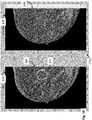
FIG. 10 depicts thework station display 122, wherein a different synthesized2D breast image 142 is displayed in the left-hand side C-View monitor 124. The synthesized2D image 142 includes a highlightedtissue structure 144, wherein the highlighting is in the form of a geometric shape, in this case a circle, to indicate that theobject 144 is a spiculated mass. Again, this highlighting may have been done automatically by the system, e.g., at the time the2D image 142 is initially displayed, or only in response to a specific user command or indication, e.g., by hovering a pointer over theobject 144 in the2D image 142. The right-hand side monitor 126 is displaying the respective tomosynthesis image 146 (which is slice no. 33 of the tomosynthesis volume stack, as indicated in the lower right hand side of the monitor 126), which is the source image or which otherwise provides a most similar view of the highlightedtissue structure 144 as seen in thesynthesized image 132. - It should be appreciated that there will be instances in which the mapping between an object or region in the merged 2D image to the respective object or region in the displayed (i.e., source or "best") image may not necessarily be 1-to-1, and will possibly be "1-to-many" in certain circumstances, for example, when multiple line structures on different tomosynthesis image slices combine together to form a line-crossing structures in the synthesized 2D image. By way of example, ,
FIG. 11 depicts the userwork station display 122, including the same synthesized2D breast image 142 as displayed inFIG. 10 , but now highlighting aregion 154 containing micro-calcifications, with the right-hand side monitor displaying the tomosynthesis image slice 156 (which is slice no. 29 of the tomosynthesis volume stack, as indicated in the lower right hand side of the monitor 126), from which the highlightedregion 154 was imported into the2D image 142, or which otherwise provides a best view of the micro-calcifications. In particular, because the spiculatedmass structure 144 and region ofmicro-calcifications 154 are in very close proximity in FIG. 142, a different one may be highlighted depending on a specific user command (e.g., to highlight a certain tissue type), or by slight adjustment of the position of the pointer of the user interface. - As explained above, this above described examples with respect to
FIGS. 9-11 are readily accomplished by the index map constructed at the same time (or after - depending on the system implementation) the synthesized 2D image is generated. Alternatively, if no index map is available, for any given such user selected/specified point/location on the 2D image displayed in the left-hand-side monitor 124, the system may execute an algorithm to automatically compute the best corresponding image (i.e., X,Y and Z) within the tomosynthesis stack for display on the right-hand-side monitor 126. A "tomosynthesis slice indicator" may optionally be provided on the left-hand-side monitor 124, which indicates which tomosynthesis slice number (numbers) would be displayed on the right-hand-side monitor 126 based on a current location of a user curser on the 2D image. With this feature, the reviewer need not be distracted by constantly changing image displays on the right-hand-side monitor 126, while still providing the reviewer with an understanding of the z-axis location in the tomosynthesis volume stack of a particular object in the 2D image. - In accordance with a further aspect of the disclosed inventions, the available features of the user interface may be extended to function, not only based point/location of the merged image, but also based in a similar fashion on a structure/object/region. For example, particular objects or region(s) in the merged image may be automatically highlighted when displayed, based on the system recognition of possible interest in the respective objects, or of objects located in the respective region(s). In one embodiment, shown in
FIG. 8 , this highlighting is in the form of acontour line 108 that represents a boundary of a highlighted tissue structure. A contour line may be similarly used to highlight regions of interest in the displayed image, e.g., containing a number of calcification structures. In some embodiments, the system is configured to allow the user to "draw" a contour line on the merged image as a way of selecting or otherwise indicating an object or region of interest for causing the system to concurrently display one or more underlying source images of the selected or indicated object or region. - In preferred embodiments, the system employs known image processing techniques to identify different breast tissue structures in the various source images, and highlight them in the merged image, in particular, tissue structures comprising or related to abnormal objects, such as micro-calcification clusters, round-or-lobulated masses, spiculated masses, architectural distortions, etc.; as well as benign tissue structures comprising or related to normal breast tissues, such as linear tissues, cysts, lymph nodes, blood vessels, etc. Furthermore, an object or region consisting of or containing a first type of tissue structure may be highlighted in a first manner in the displayed merged image, and an object or region consisting or containing a second type of tissue structure may be highlighted in a second manner different from the first manner in the displayed merged image.
- In various embodiments, the user may input a command through the user interface selecting or otherwise identifying a certain type of tissue structure, and, in response to the received command, the system performs one or both of (i) automatically highlighting in the displayed merged image objects comprising the selected type of tissue structure and/or regions containing one or more objects comprising the selected type of tissue structure, and (ii) automatically concurrently displaying the respective source slice (or otherwise the slice with best depiction of) a tissue structure of the selected type in the breast image data, e.g., a most prominent one of the selected tissue structure type based on a comparison, if more than one is detected in the source image stack. Thus, when the user "click" on (or very close to) a micro-calcification spot/cluster in the merged 2D image, and the system automatically concurrently displays the source (or otherwise best) tomosynthesis image slice including the corresponding micro-calcification in 3D. By way of another example, a user can select (through the user interface) a region in the 2D merged image that has the appearance with radiating line patterns (often an indication of spiculated masses), and the system will concurrently display the source (or otherwise best) 3D tomosynthesis slice, or perhaps to a series of consecutive tomosynthesis slices, for viewing the radiating line patterns.
- In various embodiments, the user may input a command through the user interface, activating dynamic display functionality, wherein the system automatically highlights those objects and tissue structures that (dynamically) correspond to the location of a user movable input device in the displayed merged image. In such embodiments, the system may further comprise automatically concurrently displaying a respective source image of a highlighted selected tissue structure that corresponds to a given location of a user movable input device in the displayed merged image, again, on a dynamic basis.
- In one embodiment, the system can be activated to provide a "shadow" cursor is displayed on the right-hand-
side monitor 126, in a location corresponding to the same (x,y) location as the user's actual curser on the left-hand-side monitor 124, so that moving the curser around in the 2D image moves the shadow curser in the tomosynthesis image at same X,Y coordinates. The reverse can also be implemented, i.e., with the active user curser operable in the right-hand monitor 126, and the show curser in the left-hand monitor 124. In one implementation, this dynamic display feature allows the system to follow the user's point of interest, e.g. mouse cursor location, in the 2d merged image, and dynamically display/highlight the most "meaningful" region(s) underneath in real time. For example, the user can move the mouse (without clicking any button) over a blood vessel, and the system will instantly highlight the vessel contour. - It should be appreciated that the presently disclosed inventions may be extended such that, rather than generate merely a synthesized 2D image and associated index/guidance map, the mapping concepts described herein may be extended to generate a fully mapped 3D volume, with each of the voxels in the mapped volume storing information related to the associated tomosynthesis slices(s) sourcing the particular voxel. For example, in one embodiment, the volume may be projected onto a fixed coordinate system, regardless of the actual volume of the breast. Projecting the volume to a fixed coordinate system in this manner facilitates processing of the image data, in particular, simplifying the correlation of voxels obtained during different acquisitions. For example, facilitating correlation of voxels in a 3D volume obtained from a CC acquisition of a breast with voxels in a volume obtained from an MLO acquisition of the same breast. In such an arrangement, one or more 3D maps may be provided, for example, to map from voxels in one slice of a 3D volume acquired via CC to one or more corresponding voxels in another volume, for example acquired via an MLO view. Such an arrangement facilitates comparison of slices obtained from different acquisitions that relate to a similar feature of interest within the breast volume, essentially permitting the medical professional to obtain a multi-planar review of a region of interest.
- Having described exemplary embodiments, it can be appreciated that the examples described above and depicted in the accompanying figures are only illustrative, and that other embodiments and examples also are encompassed within the scope of the appended claims. For example, while the flow diagrams provided in the accompanying figures are illustrative of exemplary steps; the overall image merge process may be achieved in a variety of manners using other data merge methods known in the art. The system block diagrams are similarly representative only, illustrating functional delineations that are not to be viewed as limiting requirements of the disclosed inventions. Thus the above specific embodiments are illustrative, and many variations can be introduced on these embodiments without departing from the scope of the appended claims.
- Clauses:
- 1. A method for processing, displaying and navigating breast tissue images, comprising:
- obtaining a plurality of 2D and/or 3D images of a patient's breast;
- generating a synthesized 2D image of the patient's breast from the obtained 2D and/or 3D images of the plurality;
- displaying the synthesized 2D image;
- receiving a user command, or otherwise detecting through a user interface, a user selection or other indication of an object or region in the synthesized 2D image; and
- displaying at least a portion of one or more images from the plurality, including a source image and/or most similar representation of the user selected or indicated object or region.
- 2. The method of
clause 1, wherein the plurality of 2D and/or 3D images of a patient's breast comprises acquired or synthesized X,Y coordinate slices at differing z axis locations of the breast, the images having one or more corresponding X,Y coordinate locations. - 3. The method of
clause - 4. The method of
clause 3, wherein objects or regions are imported into the merged image at X,Y coordinate locations corresponding to the X,Y coordinate locations of the respective objects or regions in their source image. - 5. The method of
clause - 6. The method of
clause 5, wherein at least one of the one or more attributes is user selected. - 7. The method of any of clauses 1-6, further comprising generating an index map comprising identifying information of selected images of the plurality of 2D and/or 3D images that are source images or that otherwise contain a most similar representation of regions and/or objects displayed in the synthesized 2D image.
- 8. The method of any of clauses 1-7, wherein an object or region is automatically highlighted in the synthesized 2D image and/or displayed at least portion of the one or more images from the plurality.
- 9. The method of any of clauses 1-7, further comprising highlighting an object or region in the synthesized 2D image and/or displayed at least portion of the one or more images from the plurality in response to a further received user command or to certain user activity detected through the user interface.
- 10. The method of clause 8 or 9, wherein the object or region is highlighted by a contour line representing a boundary of the highlighted object or region.
- 11. The method of clause 8 or 9, wherein the object or region is highlighted in a manner indicating that the highlighted object or region is or contains a specified type of tissue structure.
- 12. The method of any of the above clausesl-14, wherein the plurality of 2D and/or 3D images is selected from a group consisting of tomosynthesis projection images, tomosynthesis reconstruction slices, mammography images, contrast enhanced mammography images, synthesized 2D images, and combinations thereof.
- 13. A method for processing, displaying and navigating breast tissue images, comprising:
- obtaining a plurality of tomosynthesis images comprising volumetric image data of a patient's breast;
- generating a synthesized 2D image of the patient's breast at least in part from the tomosynthesis images;
- displaying the synthesized 2D image;
- receiving a user command, or otherwise detecting through a user interface, a user selection or other indication of an object or region in the synthesized 2D image; and
- displaying at least a portion of one or more tomosynthesis images from the plurality, including a source image and/or most similar representation of the user selected or indicated object or region.
- 14. The method of clause13, further comprising generating an index map, the index map comprising identifying information of selected tomosynthesis images of the plurality that are source images or that otherwise contain a most similar representation of regions and/or objects in the synthesized 2D image.
- 15. A method for processing, displaying and navigating breast tissue images, comprising:
- obtaining a plurality of 2D and/or 3D images of a patient's breast;
- generating a synthesized 2D image of the patient's breast from the obtained 2D and/or 3D images of the plurality;
- displaying the synthesized 2D image;
- detecting through a user interface a location of a user movable input device in the displayed synthesized 2D image; and
- concurrently displaying a respective source image and/or most similar representation of a tissue structure or region that corresponds to a given location of a user movable input device in the displayed synthesized 2D image.
- 16. A system for processing, displaying and navigating breast tissue images, comprising:
- an image processing computer;
- at least one image display monitor; and
- a user interface operatively coupled to the image processing computer,
- wherein the image processing computer is configured to generate a synthesized 2D image of a patient's breast from a plurality of 2D and/or 3D images of the breast, and to display the synthesized 2D image on the at least one image a display monitor, and
- wherein the image processing computer is further configured to cause to be displayed on a same or different display monitor of the one or more display monitors at least a portion of one or more images from the plurality of 2D and 3D images, including a source image or most similar representation of a user selected or indicated object or region in the synthesized 2D image.
- 17. The system of clause 16, wherein the plurality of 2D and/or 3D images comprises acquired or synthesized X,Y coordinate slices at differing z axis locations of the patient's breast, the images having one or more corresponding X,Y coordinate locations.
- 18. The system of clause 16 or 17, wherein the image processing computer generates the synthesized 2D image by constructing a merged image by importing one or more objects and/or regions from the images of the plurality of 2D and/or 3D images into the merged image, and wherein an image of the plurality from which an object or region is imported into the merged image comprises a source image for that object or region.
- 19. The system of
clause 18, wherein objects or regions are imported into the merged image at X,Y coordinate locations corresponding to the X,Y coordinate locations of the respective objects or regions in their source image. - 20. The system of
clause 18 or 19, wherein each image of the plurality of 2D and/or 3D images contains one or more regions defined by their X,Y coordinate locations that are common for all images of the plurality, and wherein one of each said common region is imported from the plurality of images into the merged image by the image processing computer based upon a comparison of one or more attributes of the respective common region of each image. - 21. The system of
clause 20, wherein at least one of the one or more attributes is user selected. - 22. The system of any of clauses 16-21, the image processing computer being further configured for generating an index map comprising identifying information of selected images of the plurality of 2D and/or 3D images that are source images or that otherwise contain a most similar representation of regions and/or objects displayed in the synthesized 2D image.
- 23. The system of any of clauses 16-22, the image processing computer being further configured for highlighting an object or region of interest in the synthesized 2D image.
- 24. The system of any of clauses 16-23, wherein the image processing computer is configured to highlight objects or regions in the displayed synthesized 2D image in response to a received user command or to certain user activity detected through the user interface.
- 25. The system of clause 23 or 24, wherein the image processing computer is configured to highlight objects or regions in the displayed synthesized 2D image with a contour line representing a boundary of the highlighted object or region.
- 26. The system of clause 23 or 24, wherein the image processing computer is configured to highlight object or regions in the displayed synthesized 2D image in a manner indicating that the highlighted object or region is or contains a specified type of tissue structure.
- 27. The system of any of the above clauses16-26, wherein the plurality of 2D and/or 3D images is selected from a group consisting of tomosynthesis projection images, tomosynthesis reconstruction slices, mammography images, contrast enhanced mammography images, synthesized 2D images, and combinations thereof.
- 28. A system for processing, displaying and navigating breast tissue images, comprising:
- an image processing computer;
- at least one image display monitor; and
- a user interface operatively coupled to the image processing computer,
- wherein the image processing computer is configured to generate a synthesized 2D image of a patient's breast from a plurality of tomosynthesis images comprising volumetric image data of a patient's breast, and to display the synthesized 2D image on the at least one image a display monitor, and
- wherein the image processing computer is further configured to cause to be displayed on a same or different display monitor of the one or more display monitors at least a portion of one or more tomosythesis images from the plurality of tomosynthesis images, including a source image or most similar representation of a user selected or indicated object or region in the synthesized 2D image.
- 29. The system of clause 28, the image processing computer further configured for generating an index map, the index map comprising identifying information of selected tomosynthesis images of the plurality that are source images or that otherwise contain a most similar representation of regions and/or objects in the synthesized 2D image.
- 30. A system for processing, displaying and navigating breast tissue images, comprising:
- an image processing computer;
- at least one image display monitor; and
- a user interface operatively coupled to the image processing computer,
- wherein the image processing computer is configured to generate a synthesized 2D image of a patient's breast from a plurality of 2D and/or 3D images of the breast, and to display the synthesized 2D image on the at least one image a display monitor, and
- wherein the image processing computer is further configured to
- (i) detect through the user interface, a location of a user movable input device in the displayed synthesized 2D image; and
- (ii) concurrently display in a same or different display monitor of the one or more display monitors a respective source image and/or most similar representation of a tissue structure or region that corresponds to a given location of a user movable input device in the displayed synthesized 2D image.
Claims (15)
- A method for processing, displaying and navigating breast tissue information, comprising:obtaining a plurality of tomosynthesis images (Tr, Tp) of a patient's breast;generating a synthesized 2D image of the patient's breast only from the obtained plurality of tomosynthesis images, the synthesized 2D image similar to that of a conventional 2D mammographic image, wherein generating the synthesized 2D image comprises constructing a merged image (Imerge) by importing one or more regions from one or more of the plurality of tomosynthesis images into the merged image, in which the one or more regions imported into the merged image comprises at least a portion of one or more source tomosynthesis images for that region;displaying the synthesized 2D image;receiving a user indication of a region of interest in the synthesized 2D image; anddisplaying at least the portion of one or more source tomosynthesis images.
- The method of claim 1, wherein the tomosyntesis images are X,Y coordinate slices at differing Z-axis locations of the breast, the images have one ore more corresponding X,Y coordinate locations, and wherein regions are imported into the merged image at X,Y coordinate locations corresponding to the X,Y coordinate locations of the respective regions in their source image.
- The method of claim 2, wherein each image of the plurality of tomosynthesis images contains one or more regions defined by their X,Y coordinate locations that are common for all images of the plurality, and wherein one of each said common region is imported from the plurality of images into the merged image based upon a comparison of one or more attributes of the respective common region of each image.
- The method of claim 3, wherein at least one of the one or more attributes is user selected.
- The method of any of the previous claims, further comprising generating an index map comprising identifying information of the source tomosynthesis images that form the merged image.
- The method of any of the previous claims, wherein the region is automatically highlighted in the synthesized 2D image and/or displayed in at least a portion of the one or more images from the plurality of source tomosynthesis images; and/or
further comprising highlighting the region in the synthesized 2D image and/or displayed in at least portion of the one or more images from the plurality of source tomosynthesis images in response to a further received user command or to certain user activity detected through the user interface,
wherein preferably the region is highlighted by a contour line representing a boundary of the highlighted object or region or wherein the region is highlighted in a manner indicating that the highlighted region is or contains a specified type of tissue structure. - The method of any of the foregoing claims in which the one or more regions are based upon the application of one or more CAD algorithms to the source tomosynthesis images.
- The method of claim 7, in which the one or more CAD algorithms assign numerical values, weights or thresholds to pixels or regions of the respective source tomosynthesis images.
- The method of claim 8, wherein displaying includes displaying the pixels of the portion of the one or more source tomosynthesis images.
- The method of any of the foregoing claims, in which the display of the portion of the one or more source tomosynthesis images is concurrently displayed with the synthesized 2D images.
- A system for processing, displaying and navigating breast tissue information, comprising:an image processing computer;at least one image display monitor; anda user interface operatively coupled to the image processing computer,wherein the image processing computer is configured to generate a synthesized 2D image of a patient's breast from only a plurality of tomosynthesis images (Tr, Tp) of the breast, the synthesized 2D image being similar to that of a conventional 2D mammographic image, wherein the synthesized 2D image is generated by constructing a merged image (Imerge) by importing one or more regions from one or more of the plurality of tomosynthesis images into the merged image, in which the one or more regions imported into the merged image comprises at least a portion of one or more source tomosynthesis images for that region,wherein the image processing computer is configured to display the synthesized 2D image on the at least one image a display monitor, andwherein the image processing computer is further configured to cause to be displayed on a same or different display monitor of the one or more display monitors at least the portion of one of the source tomosynthesis images in response to a user selection or indication of a region of interest in the synthesized 2D image.
- The system of claim 11, the image processing computer being further configured for generating an index map comprising identifying information of selected images of the plurality of tomosynthesis images that are source images or that otherwise contain a most similar representation of regions and/or objects displayed in the synthesized 2D image.
- The system of claim 11 or 12, wherein the image processing computer being further configured for highlighting an object or region of interest in the synthesized 2D image, and/or
wherein the image processing computer is configured to highlight objects or regions in the displayed synthesized 2D image in response to a received user command or to certain user activity detected through the user interface,
wherein preferably the image processing computer is configured to highlight objects or regions in the displayed synthesized 2D image with a contour line representing a boundary of the highlighted object or region or the image processing computer is configured to highlight object or regions in the displayed synthesized 2D image in a manner indicating that the highlighted object or region is or contains a specified type of tissue structure. - The system of any of the claims 11-13, in which the image processor computer is arranged to base one or more regions upon the application of one or more CAD algorithms to the source tomosynthesis images,
wherein preferably the image processor computer using the one or more CAD algorithms is arranged to assign numerical values, weights or thresholds to pixels or regions of the respective source tomosynthesis images,
wherein more preferably the image processor computer is arranged to display the pixels of the portion of the one or more source tomosynthesis images, - The system of any of the claims 11-14, wherein the image processor computer is arranged to display the portion of the one or more source tomosynthesis images concurrently with the synthesized 2D images.
Applications Claiming Priority (3)
| Application Number | Priority Date | Filing Date | Title |
|---|---|---|---|
| US201261597958P | 2012-02-13 | 2012-02-13 | |
| PCT/US2013/025993 WO2013123091A1 (en) | 2012-02-13 | 2013-02-13 | System and method for navigating a tomosynthesis stack using synthesized image data |
| EP13749870.5A EP2814396B1 (en) | 2012-02-13 | 2013-02-13 | System and method for navigating a tomosynthesis stack using synthesized image data |
Related Parent Applications (1)
| Application Number | Title | Priority Date | Filing Date |
|---|---|---|---|
| EP13749870.5A Division EP2814396B1 (en) | 2012-02-13 | 2013-02-13 | System and method for navigating a tomosynthesis stack using synthesized image data |
Publications (2)
| Publication Number | Publication Date |
|---|---|
| EP3315072A1 true EP3315072A1 (en) | 2018-05-02 |
| EP3315072B1 EP3315072B1 (en) | 2020-04-29 |
Family
ID=48984668
Family Applications (2)
| Application Number | Title | Priority Date | Filing Date |
|---|---|---|---|
| EP17176956.5A Active EP3315072B1 (en) | 2012-02-13 | 2013-02-13 | System and method for navigating a tomosynthesis stack using synthesized image data |
| EP13749870.5A Active EP2814396B1 (en) | 2012-02-13 | 2013-02-13 | System and method for navigating a tomosynthesis stack using synthesized image data |
Family Applications After (1)
| Application Number | Title | Priority Date | Filing Date |
|---|---|---|---|
| EP13749870.5A Active EP2814396B1 (en) | 2012-02-13 | 2013-02-13 | System and method for navigating a tomosynthesis stack using synthesized image data |
Country Status (6)
| Country | Link |
|---|---|
| US (5) | US9805507B2 (en) |
| EP (2) | EP3315072B1 (en) |
| JP (2) | JP6240097B2 (en) |
| CN (1) | CN104135935A (en) |
| ES (1) | ES2641456T3 (en) |
| WO (1) | WO2013123091A1 (en) |
Cited By (1)
| Publication number | Priority date | Publication date | Assignee | Title |
|---|---|---|---|---|
| EP4101385A4 (en) * | 2020-02-04 | 2023-07-19 | FUJIFILM Corporation | Image setting device, method, and program |
Families Citing this family (51)
| Publication number | Priority date | Publication date | Assignee | Title |
|---|---|---|---|---|
| US8571289B2 (en) | 2002-11-27 | 2013-10-29 | Hologic, Inc. | System and method for generating a 2D image from a tomosynthesis data set |
| WO2007095330A2 (en) | 2006-02-15 | 2007-08-23 | Hologic Inc | Breast biopsy and needle localization using tomosynthesis systems |
| WO2011043838A1 (en) | 2009-10-08 | 2011-04-14 | Hologic, Inc . | Needle breast biopsy system and method of use |
| WO2012071429A1 (en) | 2010-11-26 | 2012-05-31 | Hologic, Inc. | User interface for medical image review workstation |
| AU2012225398B2 (en) | 2011-03-08 | 2017-02-02 | Hologic, Inc. | System and method for dual energy and/or contrast enhanced breast imaging for screening, diagnosis and biopsy |
| KR102109588B1 (en) | 2011-11-27 | 2020-05-12 | 홀로직, 인크. | Methods for processing, displaying and navigating breast tissue images |
| ES2641456T3 (en) * | 2012-02-13 | 2017-11-10 | Hologic, Inc. | System and method for navigating a tomosynthesis stack using synthesized image data |
| US20130342577A1 (en) * | 2012-06-20 | 2013-12-26 | Carestream Health, Inc. | Image synthesis for diagnostic review |
| WO2014110283A1 (en) | 2013-01-10 | 2014-07-17 | Hologic, Inc. | System and method for reducing data transmission volume in tomosynthesis |
| US10092358B2 (en) | 2013-03-15 | 2018-10-09 | Hologic, Inc. | Tomosynthesis-guided biopsy apparatus and method |
| KR102340594B1 (en) * | 2013-10-24 | 2021-12-20 | 앤드류 피 스미스 | System and method for navigating x-ray guided breast biopsy |
| CN105979875B (en) * | 2014-02-04 | 2019-12-31 | 皇家飞利浦有限公司 | Medical imaging device, method, apparatus and computer readable medium for generating a breast parameter map |
| US9613440B2 (en) | 2014-02-12 | 2017-04-04 | General Electric Company | Digital breast Tomosynthesis reconstruction using adaptive voxel grid |
| US20170169609A1 (en) * | 2014-02-19 | 2017-06-15 | Koninklijke Philips N.V. | Motion adaptive visualization in medical 4d imaging |
| WO2015130916A1 (en) | 2014-02-28 | 2015-09-03 | Hologic, Inc. | System and method for generating and displaying tomosynthesis image slabs |
| US10146424B2 (en) * | 2014-02-28 | 2018-12-04 | Dell Products, Lp | Display of objects on a touch screen and their selection |
| EP3662840B1 (en) * | 2014-09-16 | 2023-12-13 | Sirona Dental, Inc. | Methods, systems, apparatuses, and computer programs for processing tomographic images |
| JP6126058B2 (en) * | 2014-09-30 | 2017-05-10 | 富士フイルム株式会社 | Image display apparatus, image processing apparatus, radiographic imaging system, tomographic image display method, and tomographic image display program. |
| JP6766045B2 (en) * | 2014-11-20 | 2020-10-07 | コーニンクレッカ フィリップス エヌ ヴェKoninklijke Philips N.V. | How to generate a synthetic mammogram from tomosynthesis data |
| CN107405126B (en) * | 2015-03-10 | 2022-01-25 | 皇家飞利浦有限公司 | Retrieving corresponding structures of pairs of medical images |
| US9792703B2 (en) * | 2015-07-06 | 2017-10-17 | Siemens Healthcare Gmbh | Generating a synthetic two-dimensional mammogram |
| JP6456550B2 (en) | 2015-09-01 | 2019-01-23 | コーニンクレッカ フィリップス エヌ ヴェKoninklijke Philips N.V. | Device for displaying medical image data of a body part |
| US9990713B2 (en) * | 2016-06-09 | 2018-06-05 | Definiens Ag | Detecting and visualizing correlations between measured correlation values and correlation reference values of a pathway |
| JP6827739B2 (en) * | 2016-08-31 | 2021-02-10 | キヤノン株式会社 | Image display device, image display method and program |
| CN106407687A (en) * | 2016-09-22 | 2017-02-15 | 沈阳东软医疗系统有限公司 | A DICOM image combination method and device |
| US10157460B2 (en) | 2016-10-25 | 2018-12-18 | General Electric Company | Interpolated tomosynthesis projection images |
| US10096106B2 (en) | 2016-11-10 | 2018-10-09 | General Electric Company | Combined medical imaging |
| US10463333B2 (en) | 2016-12-13 | 2019-11-05 | General Electric Company | Synthetic images for biopsy control |
| JP7169986B2 (en) * | 2017-03-30 | 2022-11-11 | ホロジック, インコーポレイテッド | Systems and methods for synthesizing low-dimensional image data from high-dimensional image data using object grid augmentation |
| JP7174710B2 (en) * | 2017-03-30 | 2022-11-17 | ホロジック, インコーポレイテッド | Systems and Methods for Targeted Object Augmentation to Generate Synthetic Breast Tissue Images |
| EP3600047A1 (en) | 2017-03-30 | 2020-02-05 | Hologic, Inc. | System and method for hierarchical multi-level feature image synthesis and representation |
| US11704850B2 (en) | 2017-04-07 | 2023-07-18 | Formus Labs Limited | System for transmitting and viewing a series of images |
| US11403483B2 (en) | 2017-06-20 | 2022-08-02 | Hologic, Inc. | Dynamic self-learning medical image method and system |
| US10702217B2 (en) * | 2017-08-24 | 2020-07-07 | General Electric Company | System and method for imaging a patient |
| CN109840898A (en) * | 2017-11-24 | 2019-06-04 | 通用电气公司 | A kind of the imaging display methods and imaging device of medical image |
| EP3518182B1 (en) * | 2018-01-26 | 2022-05-18 | Siemens Healthcare GmbH | Tilted slices in dbt |
| US11442591B2 (en) * | 2018-04-09 | 2022-09-13 | Lockheed Martin Corporation | System, method, computer readable medium, and viewer-interface for prioritized selection of mutually occluding objects in a virtual environment |
| US11204677B2 (en) * | 2018-10-22 | 2021-12-21 | Acclarent, Inc. | Method for real time update of fly-through camera placement |
| JP7236948B2 (en) | 2019-07-16 | 2023-03-10 | 富士フイルム株式会社 | Image processing system, image processing method, and image processing program |
| US11883206B2 (en) | 2019-07-29 | 2024-01-30 | Hologic, Inc. | Personalized breast imaging system |
| CN114746953A (en) | 2019-09-27 | 2022-07-12 | 豪洛捷公司 | AI system for predictive review of reading time and reading complexity of 2D/3D breast images |
| JP2022554190A (en) * | 2019-10-25 | 2022-12-28 | ディープヘルス, インコーポレイテッド | System and method for analyzing three-dimensional image data |
| CN110991050B (en) * | 2019-12-06 | 2022-10-14 | 万翼科技有限公司 | CAD (computer-aided design) image stacking method and related product |
| WO2021157181A1 (en) * | 2020-02-04 | 2021-08-12 | 富士フイルム株式会社 | Image setting device, method, and program |
| WO2021182076A1 (en) * | 2020-03-09 | 2021-09-16 | 富士フイルム株式会社 | Display control device, display control method, and display control program |
| CN115297778A (en) * | 2020-03-18 | 2022-11-04 | 富士胶片株式会社 | Image processing apparatus, method and program |
| US11481038B2 (en) | 2020-03-27 | 2022-10-25 | Hologic, Inc. | Gesture recognition in controlling medical hardware or software |
| CN111430011B (en) * | 2020-03-31 | 2023-08-29 | 杭州依图医疗技术有限公司 | Display method, processing method and storage medium for cell staining image |
| WO2022018943A1 (en) * | 2020-07-22 | 2022-01-27 | 富士フイルム株式会社 | Image processing device, method, and program |
| CN113052166A (en) * | 2021-02-05 | 2021-06-29 | 杭州依图医疗技术有限公司 | Pathological image display method and device |
| WO2023140475A1 (en) * | 2022-01-21 | 2023-07-27 | 주식회사 루닛 | Apparatus and method for linking lesion location between guide image and 3d tomosynthesis images including plurality of 3d image slices, and providing linked image |
Citations (11)
| Publication number | Priority date | Publication date | Assignee | Title |
|---|---|---|---|---|
| US4907156A (en) | 1987-06-30 | 1990-03-06 | University Of Chicago | Method and system for enhancement and detection of abnormal anatomic regions in a digital image |
| US5133020A (en) | 1989-07-21 | 1992-07-21 | Arch Development Corporation | Automated method and system for the detection and classification of abnormal lesions and parenchymal distortions in digital medical images |
| US5343390A (en) | 1992-02-28 | 1994-08-30 | Arch Development Corporation | Method and system for automated selection of regions of interest and detection of septal lines in digital chest radiographs |
| US5491627A (en) | 1993-05-13 | 1996-02-13 | Arch Development Corporation | Method and system for the detection of microcalcifications in digital mammograms |
| US20090080765A1 (en) * | 2007-09-20 | 2009-03-26 | General Electric Company | System and method to generate a selected visualization of a radiological image of an imaged subject |
| US7577282B2 (en) | 2002-11-27 | 2009-08-18 | Hologic, Inc. | Image handling and display in X-ray mammography and tomosynthesis |
| US7606801B2 (en) | 2005-06-07 | 2009-10-20 | Varonis Inc. | Automatic management of storage access control |
| US7702142B2 (en) | 2004-11-15 | 2010-04-20 | Hologic, Inc. | Matching geometry generation and display of mammograms and tomosynthesis images |
| US20100135558A1 (en) | 2002-11-27 | 2010-06-03 | Chris Ruth | System and Method for Generating a 2D Image from a Tomosynthesis Data Set |
| US7760924B2 (en) | 2002-11-27 | 2010-07-20 | Hologic, Inc. | System and method for generating a 2D image from a tomosynthesis data set |
| US20110110576A1 (en) * | 2009-10-07 | 2011-05-12 | Hologic, Inc. | Selective Display Of Computer-Aided Detection Findings With Associated Breast X-Ray Mammogram and/or Tomosynthesis Image Information |
Family Cites Families (395)
| Publication number | Priority date | Publication date | Assignee | Title |
|---|---|---|---|---|
| JP4054402B2 (en) | 1997-04-25 | 2008-02-27 | 株式会社東芝 | X-ray tomography equipment |
| US3502878A (en) | 1967-09-22 | 1970-03-24 | Us Health Education & Welfare | Automatic x-ray apparatus for limiting the field size of a projected x-ray beam in response to film size and to source-to-film distance |
| US7050611B2 (en) | 2001-05-29 | 2006-05-23 | Mevis Breastcare Gmbh Co. Kg | Method and computer system for screening of medical cases |
| US3863073A (en) | 1973-04-26 | 1975-01-28 | Machlett Lab Inc | Automatic system for precise collimation of radiation |
| US3971950A (en) | 1975-04-14 | 1976-07-27 | Xerox Corporation | Independent compression and positioning device for use in mammography |
| US4160906A (en) | 1977-06-23 | 1979-07-10 | General Electric Company | Anatomically coordinated user dominated programmer for diagnostic x-ray apparatus |
| DE2838901C2 (en) | 1978-09-06 | 1986-11-06 | Siemens AG, 1000 Berlin und 8000 München | Catapult drawer |
| FR2512024A1 (en) | 1981-08-27 | 1983-03-04 | Adir | TRICYCLIC ETHERS, PREPARATION THEREOF AND PHARMACEUTICAL COMPOSITIONS CONTAINING THEM |
| FR2549248B1 (en) | 1983-06-24 | 1986-01-31 | Thomson Csf | RETRACTABLE CASSETTE HOLDER FOR RADIOLOGICAL AND RADIOGRAPHIC EXAMINATION APPARATUS |
| DE3339775A1 (en) | 1983-11-03 | 1985-05-15 | Siemens AG, 1000 Berlin und 8000 München | X-RAY DIAGNOSTIC DEVICE WITH RADIATION FILTERS |
| JPS60129034A (en) | 1983-12-16 | 1985-07-10 | 横河メディカルシステム株式会社 | Operation table of x-ray tomographic apparatus |
| US4706269A (en) | 1985-03-11 | 1987-11-10 | Reina Leo J | Anti-scatter grid structure |
| US4773087A (en) | 1986-04-14 | 1988-09-20 | University Of Rochester | Quality of shadowgraphic x-ray images |
| USRE33634E (en) | 1986-09-23 | 1991-07-09 | Method and structure for optimizing radiographic quality by controlling X-ray tube voltage, current focal spot size and exposure time | |
| US4821727A (en) | 1986-10-30 | 1989-04-18 | Elscint Ltd. | Mammographic biopsy needle holder system |
| US4819258A (en) | 1986-11-28 | 1989-04-04 | Bennett X-Ray Corp. | Auto-setting of KV in an x-ray machine after selection of technic factors |
| US5051904A (en) | 1988-03-24 | 1991-09-24 | Olganix Corporation | Computerized dynamic tomography system |
| US5740270A (en) | 1988-04-08 | 1998-04-14 | Neuromedical Systems, Inc. | Automated cytological specimen classification system and method |
| DK654488A (en) | 1988-11-23 | 1990-05-24 | Nordisk Roentgen Tech App | ROENTGENAPPARAT |
| US5099846A (en) | 1988-12-23 | 1992-03-31 | Hardy Tyrone L | Method and apparatus for video presentation from a variety of scanner imaging sources |
| FR2645006A1 (en) | 1989-03-29 | 1990-10-05 | Gen Electric Cgr | MAMMOGRAPH HAVING INTEGRATED STEREOTAXIC VIEWING DEVICE AND METHOD OF USING SUCH A MAMMOGRAPHER |
| FR2646340A1 (en) | 1989-04-28 | 1990-11-02 | Gen Electric Cgr | ADJUSTABLE CASSETTE HOLDER IN DIMENSION AND POSITION FOR MAMMOGRAPHY |
| EP0406455B1 (en) | 1989-07-03 | 1994-09-21 | Siemens Aktiengesellschaft | X-ray diagnostic apparatus for mammographies |
| US4969174A (en) | 1989-09-06 | 1990-11-06 | General Electric Company | Scanning mammography system with reduced scatter radiation |
| CA2014918A1 (en) | 1989-09-06 | 1991-03-06 | James A. Mcfaul | Scanning mammography system with improved skin line viewing |
| US5078142A (en) | 1989-11-21 | 1992-01-07 | Fischer Imaging Corporation | Precision mammographic needle biopsy system |
| US5240011A (en) | 1991-11-27 | 1993-08-31 | Fischer Imaging Corporation | Motorized biopsy needle positioner |
| US5415169A (en) | 1989-11-21 | 1995-05-16 | Fischer Imaging Corporation | Motorized mammographic biopsy apparatus |
| AU645535B2 (en) | 1989-11-27 | 1994-01-20 | Bard International, Inc. | Puncture guide for computer tomography |
| US5199056A (en) | 1989-11-28 | 1993-03-30 | Darrah Carol J | Mammography compression paddle |
| US5481623A (en) | 1990-04-19 | 1996-01-02 | Fuji Photo Film Co., Ltd. | Apparatus for determining an image position on imaging media |
| FR2668359B1 (en) | 1990-10-24 | 1998-02-20 | Gen Electric Cgr | MAMMOGRAPH PROVIDED WITH A PERFECTED NEEDLE HOLDER. |
| US5409497A (en) | 1991-03-11 | 1995-04-25 | Fischer Imaging Corporation | Orbital aiming device for mammo biopsy |
| US5129911A (en) | 1991-03-11 | 1992-07-14 | Siczek Bernard W | Orbital aiming device |
| US5279309A (en) | 1991-06-13 | 1994-01-18 | International Business Machines Corporation | Signaling device and method for monitoring positions in a surgical operation |
| US5163075A (en) | 1991-08-08 | 1992-11-10 | Eastman Kodak Company | Contrast enhancement of electrographic imaging |
| US5941832A (en) | 1991-09-27 | 1999-08-24 | Tumey; David M. | Method and apparatus for detection of cancerous and precancerous conditions in a breast |
| US5289520A (en) | 1991-11-27 | 1994-02-22 | Lorad Corporation | Stereotactic mammography imaging system with prone position examination table and CCD camera |
| US5594769A (en) | 1991-11-27 | 1997-01-14 | Thermotrex Corporation | Method and apparatus for obtaining stereotactic mammographic guided needle breast biopsies |
| US5359637A (en) | 1992-04-28 | 1994-10-25 | Wake Forest University | Self-calibrated tomosynthetic, radiographic-imaging system, method, and device |
| US5386447A (en) | 1992-09-23 | 1995-01-31 | Fischer Imaging Corporation | Mammographic screening and biopsy apparatus |
| US5596200A (en) | 1992-10-14 | 1997-01-21 | Primex | Low dose mammography system |
| FR2703237B1 (en) | 1993-03-29 | 1995-05-19 | Ge Medical Syst Sa | Mammograph equipped with a stereotaxic camera with digital detector and method of using such a mammograph. |
| US5878746A (en) | 1993-08-25 | 1999-03-09 | Lemelson; Jerome H. | Computerized medical diagnostic system |
| US5365562A (en) | 1993-09-20 | 1994-11-15 | Fischer Imaging Corporation | Digital imaging apparatus |
| US6075879A (en) | 1993-09-29 | 2000-06-13 | R2 Technology, Inc. | Method and system for computer-aided lesion detection using information from multiple images |
| US5526394A (en) | 1993-11-26 | 1996-06-11 | Fischer Imaging Corporation | Digital scan mammography apparatus |
| US5452367A (en) | 1993-11-29 | 1995-09-19 | Arch Development Corporation | Automated method and system for the segmentation of medical images |
| CA2113752C (en) | 1994-01-19 | 1999-03-02 | Stephen Michael Rooks | Inspection system for cross-sectional imaging |
| DE4414689C2 (en) | 1994-04-26 | 1996-08-29 | Siemens Ag | X-ray diagnostic device |
| US5499097A (en) | 1994-09-19 | 1996-03-12 | Neopath, Inc. | Method and apparatus for checking automated optical system performance repeatability |
| AU3371395A (en) | 1994-09-20 | 1996-04-19 | Neopath, Inc. | Biological specimen analysis system processing integrity checking apparatus |
| US5647025A (en) | 1994-09-20 | 1997-07-08 | Neopath, Inc. | Automatic focusing of biomedical specimens apparatus |
| US5557097A (en) | 1994-09-20 | 1996-09-17 | Neopath, Inc. | Cytological system autofocus integrity checking apparatus |
| US5553111A (en) | 1994-10-26 | 1996-09-03 | The General Hospital Corporation | Apparatus and method for improved tissue imaging |
| US5506877A (en) | 1994-11-23 | 1996-04-09 | The General Hospital Corporation | Mammography breast compression device and method |
| US5712890A (en) * | 1994-11-23 | 1998-01-27 | Thermotrex Corp. | Full breast digital mammography device |
| US5657362A (en) | 1995-02-24 | 1997-08-12 | Arch Development Corporation | Automated method and system for computerized detection of masses and parenchymal distortions in medical images |
| US5671288A (en) | 1995-05-31 | 1997-09-23 | Neopath, Inc. | Method and apparatus for assessing slide and specimen preparation quality |
| US6216540B1 (en) | 1995-06-06 | 2001-04-17 | Robert S. Nelson | High resolution device and method for imaging concealed objects within an obscuring medium |
| US5820623A (en) | 1995-06-20 | 1998-10-13 | Ng; Wan Sing | Articulated arm for medical procedures |
| US5642433A (en) | 1995-07-31 | 1997-06-24 | Neopath, Inc. | Method and apparatus for image contrast quality evaluation |
| US5642441A (en) | 1995-10-24 | 1997-06-24 | Neopath, Inc. | Separation apparatus and method for measuring focal plane |
| US5818898A (en) | 1995-11-07 | 1998-10-06 | Kabushiki Kaisha Toshiba | X-ray imaging apparatus using X-ray planar detector |
| US5693948A (en) | 1995-11-21 | 1997-12-02 | Loral Fairchild Corporation | Advanced CCD-based x-ray image sensor system |
| US5627869A (en) | 1995-11-22 | 1997-05-06 | Thermotrex Corporation | Mammography apparatus with proportional collimation |
| FI955636A0 (en) | 1995-11-23 | 1995-11-23 | Planmed Oy | Foerfarande och system Foer styrning av funktionerna av en mammografiaanordning |
| US6215892B1 (en) | 1995-11-30 | 2001-04-10 | Chromavision Medical Systems, Inc. | Method and apparatus for automated image analysis of biological specimens |
| US5769086A (en) | 1995-12-06 | 1998-06-23 | Biopsys Medical, Inc. | Control system and method for automated biopsy device |
| JPH09198490A (en) | 1996-01-22 | 1997-07-31 | Hitachi Medical Corp | Three-dimensional discrete data projector |
| JPH09238934A (en) | 1996-03-11 | 1997-09-16 | Toshiba Medical Eng Co Ltd | Image display system |
| DE19619924A1 (en) | 1996-05-17 | 1997-11-20 | Siemens Ag | Tomosynthetic image generating method |
| DE19619925C2 (en) | 1996-05-17 | 1999-09-09 | Sirona Dental Systems Gmbh | X-ray diagnostic device for tomosynthesis |
| DE19619915A1 (en) | 1996-05-17 | 1997-11-20 | Siemens Ag | Process for creating tomosynthesis images |
| DE19619913C2 (en) | 1996-05-17 | 2001-03-15 | Sirona Dental Systems Gmbh | X-ray diagnostic device for tomosynthesis |
| US6067079A (en) | 1996-06-13 | 2000-05-23 | International Business Machines Corporation | Virtual pointing device for touchscreens |
| US5835079A (en) | 1996-06-13 | 1998-11-10 | International Business Machines Corporation | Virtual pointing device for touchscreens |
| US5841124A (en) | 1996-06-19 | 1998-11-24 | Neopath, Inc. | Cytological system autofocus integrity checking apparatus |
| DE69739995D1 (en) | 1996-07-23 | 2010-10-28 | Gen Hospital Corp | ARRANGEMENT TO MAMMOGRAPHY BY TOMOSYNTHESIS |
| JPH1033523A (en) | 1996-07-24 | 1998-02-10 | Hitachi Medical Corp | X-ray ct device |
| US5776062A (en) | 1996-10-15 | 1998-07-07 | Fischer Imaging Corporation | Enhanced breast imaging/biopsy system employing targeted ultrasound |
| US5986662A (en) | 1996-10-16 | 1999-11-16 | Vital Images, Inc. | Advanced diagnostic viewer employing automated protocol selection for volume-rendered imaging |
| US6293282B1 (en) | 1996-11-05 | 2001-09-25 | Jerome Lemelson | System and method for treating select tissue in living being |
| JP3878259B2 (en) | 1996-11-13 | 2007-02-07 | 東芝医用システムエンジニアリング株式会社 | Medical image processing device |
| US6137527A (en) | 1996-12-23 | 2000-10-24 | General Electric Company | System and method for prompt-radiology image screening service via satellite |
| US7117098B1 (en) | 1997-02-27 | 2006-10-03 | Cellomics, Inc. | Machine-readable storage medium for analyzing distribution of macromolecules between the cell membrane and the cell cytoplasm |
| US5999639A (en) | 1997-09-04 | 1999-12-07 | Qualia Computing, Inc. | Method and system for automated detection of clustered microcalcifications from digital mammograms |
| US20030135115A1 (en) | 1997-11-24 | 2003-07-17 | Burdette Everette C. | Method and apparatus for spatial registration and mapping of a biopsy needle during a tissue biopsy |
| US6442288B1 (en) | 1997-12-17 | 2002-08-27 | Siemens Aktiengesellschaft | Method for reconstructing a three-dimensional image of an object scanned in the context of a tomosynthesis, and apparatus for tomosynthesis |
| JP3554172B2 (en) | 1998-01-09 | 2004-08-18 | キヤノン株式会社 | Radiography equipment |
| US6175117B1 (en) | 1998-01-23 | 2001-01-16 | Quanta Vision, Inc. | Tissue analysis apparatus |
| US6289235B1 (en) | 1998-03-05 | 2001-09-11 | Wake Forest University | Method and system for creating three-dimensional images using tomosynthetic computed tomography |
| US6081577A (en) | 1998-07-24 | 2000-06-27 | Wake Forest University | Method and system for creating task-dependent three-dimensional images |
| US6375352B1 (en) | 1999-10-01 | 2002-04-23 | General Electric Company | Apparatus and method for obtaining x-ray tomosynthesis data for mammography |
| US6141398A (en) | 1998-08-25 | 2000-10-31 | General Electric Company | Protocol driven image reconstruction, display, and processing in a multislice imaging system |
| US6101236A (en) | 1998-10-02 | 2000-08-08 | University Of Iowa Research Foundation | Iterative method and apparatus for x-ray computed tomographic fluoroscopy |
| WO2000051484A2 (en) | 1998-11-25 | 2000-09-08 | Fischer Imaging Corporation | User interface system for mammographic imager |
| FR2786388B1 (en) | 1998-11-27 | 2001-02-16 | Ge Medical Syst Sa | METHOD FOR DETECTING FABRIC OF A SPECIFIC NATURE IN DIGITAL RADIOLOGY AND ITS USE FOR ADJUSTING THE EXPOSURE PARAMETERS |
| US6149301A (en) | 1998-12-30 | 2000-11-21 | General Electric Company | X-ray target centering apparatus for radiographic imaging system |
| JP2000200340A (en) | 1999-01-06 | 2000-07-18 | Ge Yokogawa Medical Systems Ltd | Method and device for displaying image and ct system |
| US6424332B1 (en) | 1999-01-29 | 2002-07-23 | Hunter Innovations, Inc. | Image comparison apparatus and method |
| CA2359322C (en) | 1999-01-29 | 2007-09-18 | American Superconductor Corporation | Electric utility system with superconducting magnetic energy storage |
| US6233473B1 (en) | 1999-02-16 | 2001-05-15 | Hologic, Inc. | Determining body composition using fan beam dual-energy x-ray absorptiometry |
| US6272207B1 (en) | 1999-02-18 | 2001-08-07 | Creatv Microtech, Inc. | Method and apparatus for obtaining high-resolution digital X-ray and gamma ray images |
| US6256370B1 (en) | 2000-01-24 | 2001-07-03 | General Electric Company | Method and apparatus for performing tomosynthesis |
| US6689142B1 (en) | 1999-04-26 | 2004-02-10 | Scimed Life Systems, Inc. | Apparatus and methods for guiding a needle |
| US6292530B1 (en) | 1999-04-29 | 2001-09-18 | General Electric Company | Method and apparatus for reconstructing image data acquired by a tomosynthesis x-ray imaging system |
| DE19922346C2 (en) | 1999-05-14 | 2003-06-18 | Siemens Ag | X-ray diagnostic device for tomosynthesis or layering |
| US6243441B1 (en) | 1999-07-13 | 2001-06-05 | Edge Medical Devices | Active matrix detector for X-ray imaging |
| US20020173721A1 (en) | 1999-08-20 | 2002-11-21 | Novasonics, Inc. | User interface for handheld imaging devices |
| US6480565B1 (en) | 1999-11-18 | 2002-11-12 | University Of Rochester | Apparatus and method for cone beam volume computed tomography breast imaging |
| US6987831B2 (en) | 1999-11-18 | 2006-01-17 | University Of Rochester | Apparatus and method for cone beam volume computed tomography breast imaging |
| US6633674B1 (en) | 1999-11-24 | 2003-10-14 | General Electric Company | Picture archiving and communication system employing improved data compression |
| US6245028B1 (en) | 1999-11-24 | 2001-06-12 | Marconi Medical Systems, Inc. | Needle biopsy system |
| US6645520B2 (en) | 1999-12-16 | 2003-11-11 | Dermatrends, Inc. | Transdermal administration of nonsteroidal anti-inflammatory drugs using hydroxide-releasing agents as permeation enhancers |
| FR2803069B1 (en) | 1999-12-28 | 2002-12-13 | Ge Medical Syst Sa | METHOD AND SYSTEM FOR COMPENSATING THE THICKNESS OF AN ORGAN |
| US6411836B1 (en) | 1999-12-30 | 2002-06-25 | General Electric Company | Method and apparatus for user preferences configuring in an image handling system |
| US8352289B2 (en) | 1999-12-30 | 2013-01-08 | Dhi Computing, Inc. | Systems and methods for providing and maintaining electronic medical records |
| US6901156B2 (en) | 2000-02-04 | 2005-05-31 | Arch Development Corporation | Method, system and computer readable medium for an intelligent search workstation for computer assisted interpretation of medical images |
| US6744848B2 (en) | 2000-02-11 | 2004-06-01 | Brandeis University | Method and system for low-dose three-dimensional imaging of a scene |
| GB0006598D0 (en) | 2000-03-17 | 2000-05-10 | Isis Innovation | Three-dimensional reconstructions from images |
| US6351660B1 (en) | 2000-04-18 | 2002-02-26 | Litton Systems, Inc. | Enhanced visualization of in-vivo breast biopsy location for medical documentation |
| US6683934B1 (en) | 2000-06-05 | 2004-01-27 | General Electric Company | Dual energy x-ray imaging system and method for radiography and mammography |
| US6327336B1 (en) | 2000-06-05 | 2001-12-04 | Direct Radiography Corp. | Radiogram showing location of automatic exposure control sensor |
| US6389104B1 (en) | 2000-06-30 | 2002-05-14 | Siemens Corporate Research, Inc. | Fluoroscopy based 3-D neural navigation based on 3-D angiography reconstruction data |
| JP2002052018A (en) | 2000-08-11 | 2002-02-19 | Canon Inc | Image display device, image display method and storage medium |
| JP2002109510A (en) | 2000-09-27 | 2002-04-12 | Fuji Photo Film Co Ltd | Possible abnormal shadow detecting and processing system |
| JP2004512081A (en) | 2000-10-20 | 2004-04-22 | コーニンクレッカ フィリップス エレクトロニクス エヌ ヴィ | Tomographic synthesis in a limited angle range |
| US6758824B1 (en) | 2000-11-06 | 2004-07-06 | Suros Surgical Systems, Inc. | Biopsy apparatus |
| WO2002069808A2 (en) | 2000-11-06 | 2002-09-12 | Suros Surgical Systems, Inc. | Biopsy apparatus |
| US6468226B1 (en) | 2000-11-22 | 2002-10-22 | Mcintyre, Iv John J. | Remote tissue biopsy apparatus and associated methods |
| US7597663B2 (en) | 2000-11-24 | 2009-10-06 | U-Systems, Inc. | Adjunctive ultrasound processing and display for breast cancer screening |
| US7103205B2 (en) | 2000-11-24 | 2006-09-05 | U-Systems, Inc. | Breast cancer screening with ultrasound image overlays |
| US7615008B2 (en) | 2000-11-24 | 2009-11-10 | U-Systems, Inc. | Processing and displaying breast ultrasound information |
| US7556602B2 (en) | 2000-11-24 | 2009-07-07 | U-Systems, Inc. | Breast cancer screening with adjunctive ultrasound mammography |
| US6650928B1 (en) | 2000-11-27 | 2003-11-18 | Ge Medical Systems Global Technology Company, Llc | Color parametric and composite maps for CT perfusion |
| US6501819B2 (en) | 2000-12-18 | 2002-12-31 | Ge Medical Systems Global Technology Company, Llc | Medical diagnostic method and apparatus to control dual energy exposure techniques based on image information |
| FR2818116B1 (en) | 2000-12-19 | 2004-08-27 | Ge Med Sys Global Tech Co Llc | MAMMOGRAPHY APPARATUS |
| EP1346322A1 (en) | 2000-12-22 | 2003-09-24 | Koninklijke Philips Electronics N.V. | Stereoscopic viewing of a region between clipping planes |
| US6463181B2 (en) | 2000-12-22 | 2002-10-08 | The United States Of America As Represented By The Secretary Of The Navy | Method for optimizing visual display of enhanced digital images |
| EP1364374A4 (en) | 2001-02-01 | 2006-11-22 | Creatv Microtech Inc | tNTI-SCATTER GRIDS AND COLLIMATOR DESIGNS, AND THEIR MOTION, FABRICATION AND ASSEMBLY |
| US7030861B1 (en) | 2001-02-10 | 2006-04-18 | Wayne Carl Westerman | System and method for packing multi-touch gestures onto a hand |
| US6486764B2 (en) | 2001-02-16 | 2002-11-26 | Delphi Technologies, Inc. | Rotary position sensor |
| US20020188466A1 (en) | 2001-04-18 | 2002-12-12 | Barrette Pierre Philip | Secure digital medical intellectual property (IP) distribution, market applications, and mobile devices |
| US6620111B2 (en) | 2001-04-20 | 2003-09-16 | Ethicon Endo-Surgery, Inc. | Surgical biopsy device having automatic rotation of the probe for taking multiple samples |
| US6954667B2 (en) | 2001-06-28 | 2005-10-11 | Chemimage Corporation | Method for Raman chemical imaging and characterization of calcification in tissue |
| US6611575B1 (en) | 2001-07-27 | 2003-08-26 | General Electric Company | Method and system for high resolution 3D visualization of mammography images |
| US20030048260A1 (en) | 2001-08-17 | 2003-03-13 | Alec Matusis | System and method for selecting actions based on the identification of user's fingers |
| AU2002332758A1 (en) | 2001-08-31 | 2003-03-18 | Analogic Corporation | Image positioning method and system for tomosynthesis in a digital x-ray radiography system |
| US20030072478A1 (en) | 2001-10-12 | 2003-04-17 | Claus Bernhard Erich Hermann | Reconstruction method for tomosynthesis |
| JP4363833B2 (en) * | 2001-10-16 | 2009-11-11 | 株式会社東芝 | Method and apparatus for calculating an index relating to local hemodynamics |
| WO2003037046A2 (en) | 2001-10-19 | 2003-05-01 | Hologic, Inc. | Mammography system and method employing offset compression paddles, automatic collimation, and retractable anti-scatter grid |
| US6626849B2 (en) | 2001-11-01 | 2003-09-30 | Ethicon Endo-Surgery, Inc. | MRI compatible surgical biopsy device |
| DE60135559D1 (en) | 2001-11-19 | 2008-10-09 | St Microelectronics Srl | Method for mixing digital images to produce a digital image with extended dynamic range |
| US6895077B2 (en) | 2001-11-21 | 2005-05-17 | University Of Massachusetts Medical Center | System and method for x-ray fluoroscopic imaging |
| US20030097055A1 (en) | 2001-11-21 | 2003-05-22 | Philips Medical Systems(Cleveland), Inc. | Method of reviewing tomographic scans with a large number of images |
| US6751285B2 (en) | 2001-11-21 | 2004-06-15 | General Electric Company | Dose management system for mammographic tomosynthesis |
| JP4099984B2 (en) * | 2001-12-14 | 2008-06-11 | コニカミノルタホールディングス株式会社 | Abnormal shadow detection apparatus and image output apparatus |
| US6978040B2 (en) | 2001-12-19 | 2005-12-20 | Canon Kabushiki Kaisha | Optical recovery of radiographic geometry |
| US6647092B2 (en) | 2002-01-18 | 2003-11-11 | General Electric Company | Radiation imaging system and method of collimation |
| SE524458C2 (en) | 2002-03-01 | 2004-08-10 | Mamea Imaging Ab | Protective device by an X-ray apparatus |
| US7346381B2 (en) | 2002-11-01 | 2008-03-18 | Ge Medical Systems Global Technology Company Llc | Method and apparatus for medical intervention procedure planning |
| US6878115B2 (en) | 2002-03-28 | 2005-04-12 | Ultrasound Detection Systems, Llc | Three-dimensional ultrasound computed tomography imaging system |
| US7218766B2 (en) | 2002-04-15 | 2007-05-15 | General Electric Company | Computer aided detection (CAD) for 3D digital mammography |
| US20030194050A1 (en) | 2002-04-15 | 2003-10-16 | General Electric Company | Multi modality X-ray and nuclear medicine mammography imaging system and method |
| US6882700B2 (en) | 2002-04-15 | 2005-04-19 | General Electric Company | Tomosynthesis X-ray mammogram system and method with automatic drive system |
| US6752767B2 (en) | 2002-04-16 | 2004-06-22 | Vivant Medical, Inc. | Localization element with energized tip |
| US7139000B2 (en) | 2002-05-13 | 2006-11-21 | Ge Medical Systems Global Technology Company, Llc | Method, system and computer product for displaying axial images |
| US7295691B2 (en) | 2002-05-15 | 2007-11-13 | Ge Medical Systems Global Technology Company, Llc | Computer aided diagnosis of an image set |
| US11275405B2 (en) | 2005-03-04 | 2022-03-15 | Apple Inc. | Multi-functional hand-held device |
| US7599579B2 (en) | 2002-07-11 | 2009-10-06 | Ge Medical Systems Global Technology Company, Llc | Interpolated image filtering method and apparatus |
| US7450747B2 (en) | 2002-07-12 | 2008-11-11 | Ge Medical Systems Global Technology Company, Llc | System and method for efficiently customizing an imaging system |
| US20040036680A1 (en) | 2002-08-26 | 2004-02-26 | Mark Davis | User-interface features for computers with contact-sensitive displays |
| US6898331B2 (en) | 2002-08-28 | 2005-05-24 | Bae Systems Aircraft Controls, Inc. | Image fusion system and method |
| US6574304B1 (en) | 2002-09-13 | 2003-06-03 | Ge Medical Systems Global Technology Company, Llc | Computer aided acquisition of medical images |
| US6748044B2 (en) | 2002-09-13 | 2004-06-08 | Ge Medical Systems Global Technology Company, Llc | Computer assisted analysis of tomographic mammography data |
| US7260249B2 (en) * | 2002-09-27 | 2007-08-21 | Confirma Incorporated | Rules-based approach for processing medical images |
| US6940943B2 (en) | 2002-10-07 | 2005-09-06 | General Electric Company | Continuous scan tomosynthesis system and method |
| US7347829B2 (en) | 2002-10-07 | 2008-03-25 | Suros Surgical Systems, Inc. | Introduction system for minimally invasive surgical instruments |
| US6825838B2 (en) * | 2002-10-11 | 2004-11-30 | Sonocine, Inc. | 3D modeling system |
| US20040171933A1 (en) | 2002-11-25 | 2004-09-02 | Milton Stoller | Mammography needle biopsy system and method |
| US7616801B2 (en) | 2002-11-27 | 2009-11-10 | Hologic, Inc. | Image handling and display in x-ray mammography and tomosynthesis |
| US7123684B2 (en) | 2002-11-27 | 2006-10-17 | Hologic, Inc. | Full field mammography with tissue exposure control, tomosynthesis, and dynamic field of view processing |
| US6597762B1 (en) | 2002-11-27 | 2003-07-22 | Ge Medical Systems Global Technology Co., Llc | Method and apparatus of lesion detection and validation based on multiple reviews of a CT image |
| US7831296B2 (en) | 2002-11-27 | 2010-11-09 | Hologic, Inc. | X-ray mammography with tomosynthesis |
| US7406150B2 (en) | 2002-11-29 | 2008-07-29 | Hologic, Inc. | Distributed architecture for mammographic image acquisition and processing |
| US7904824B2 (en) | 2002-12-10 | 2011-03-08 | Siemens Medical Solutions Usa, Inc. | Medical imaging programmable custom user interface system and method |
| US7110490B2 (en) | 2002-12-10 | 2006-09-19 | General Electric Company | Full field digital tomosynthesis method and apparatus |
| US7634308B2 (en) | 2002-12-17 | 2009-12-15 | Kabushiki Kaisha Toshiba | Method and system for X-ray diagnosis of object in which X-ray contrast agent is injected |
| US7356113B2 (en) | 2003-02-12 | 2008-04-08 | Brandeis University | Tomosynthesis imaging system and method |
| US7333644B2 (en) | 2003-03-11 | 2008-02-19 | Siemens Medical Solutions Usa, Inc. | Systems and methods for providing automatic 3D lesion segmentation and measurements |
| JP4497837B2 (en) | 2003-05-12 | 2010-07-07 | キヤノン株式会社 | Radiation imaging equipment |
| JP2007524461A (en) | 2003-06-25 | 2007-08-30 | シーメンス メディカル ソリューションズ ユーエスエー インコーポレイテッド | Mammography automatic diagnosis and decision support system and method |
| US6885724B2 (en) | 2003-08-22 | 2005-04-26 | Ge Medical Systems Global Technology Company, Llc | Radiographic tomosynthesis image acquisition utilizing asymmetric geometry |
| US8090164B2 (en) | 2003-08-25 | 2012-01-03 | The University Of North Carolina At Chapel Hill | Systems, methods, and computer program products for analysis of vessel attributes for diagnosis, disease staging, and surgical planning |
| US7424141B2 (en) | 2003-08-29 | 2008-09-09 | Agilent Technologies, Inc. | System and method for performing auto-focused tomosynthesis |
| US7578781B2 (en) | 2003-09-18 | 2009-08-25 | Wisconsin Alumni Research Foundation | Device for placement of needles and radioactive seeds in radiotherapy |
| JP2005110843A (en) * | 2003-10-06 | 2005-04-28 | Canon Inc | Radiation image processor and processing method |
| US7869862B2 (en) | 2003-10-15 | 2011-01-11 | Varian Medical Systems, Inc. | Systems and methods for functional imaging using contrast-enhanced multiple-energy computed tomography |
| US20050089205A1 (en) | 2003-10-23 | 2005-04-28 | Ajay Kapur | Systems and methods for viewing an abnormality in different kinds of images |
| JP2005149107A (en) | 2003-11-14 | 2005-06-09 | Konica Minolta Medical & Graphic Inc | Medical image management system |
| DE10353611B4 (en) | 2003-11-17 | 2013-01-17 | Siemens Aktiengesellschaft | X-ray diagnostic device for mammography examinations |
| WO2005051197A2 (en) | 2003-11-26 | 2005-06-09 | Koninklijke Philips Electronics, N.V. | Workflow optimization for high throughput imaging environment |
| US8768026B2 (en) | 2003-11-26 | 2014-07-01 | Hologic, Inc. | X-ray imaging with x-ray markers that provide adjunct information but preserve image quality |
| US8265728B2 (en) | 2003-11-26 | 2012-09-11 | University Of Chicago | Automated method and system for the evaluation of disease and registration accuracy in the subtraction of temporally sequential medical images |
| US7727151B2 (en) | 2003-11-28 | 2010-06-01 | U-Systems Inc. | Navigation among multiple breast ultrasound volumes |
| US7773721B2 (en) | 2003-12-03 | 2010-08-10 | The General Hospital Corporation | Multi-segment cone-beam reconstruction system and method for tomosynthesis imaging |
| US20050135555A1 (en) | 2003-12-23 | 2005-06-23 | Claus Bernhard Erich H. | Method and system for simultaneously viewing rendered volumes |
| US7653229B2 (en) | 2003-12-23 | 2010-01-26 | General Electric Company | Methods and apparatus for reconstruction of volume data from projection data |
| CN1933787A (en) | 2004-01-23 | 2007-03-21 | 特拉克斯医疗有限公司 | Methods and apparatus for performing procedures on target locations in the body |
| US7298881B2 (en) | 2004-02-13 | 2007-11-20 | University Of Chicago | Method, system, and computer software product for feature-based correlation of lesions from multiple images |
| US7289825B2 (en) | 2004-03-15 | 2007-10-30 | General Electric Company | Method and system for utilizing wireless voice technology within a radiology workflow |
| US7142633B2 (en) | 2004-03-31 | 2006-11-28 | General Electric Company | Enhanced X-ray imaging system and method |
| US7699783B2 (en) | 2004-04-08 | 2010-04-20 | Techniscan, Inc. | Method for imaging and treating a breast |
| EP1750584B1 (en) | 2004-05-14 | 2020-10-14 | Philips Intellectual Property & Standards GmbH | System and method for diagnosing breast cancer |
| GB0411402D0 (en) | 2004-05-21 | 2004-06-23 | Tissuomics Ltd | Penetrating radiation measurements |
| US7835562B2 (en) | 2004-07-23 | 2010-11-16 | General Electric Company | Methods and apparatus for noise reduction filtering of images |
| AU2005266901B2 (en) | 2004-07-23 | 2010-04-08 | Learning Tree International | System and method for electronic presentations |
| FR2873835A1 (en) | 2004-07-29 | 2006-02-03 | Gen Electric | METHOD AND DEVICE FOR X-RAY IMAGING WITH CONTRAST PRODUCT FOR ENHANCED VISUALIZATION |
| WO2006020874A2 (en) | 2004-08-10 | 2006-02-23 | The Research Foundation | Flat-panel detector with avalanche gain |
| US7725153B2 (en) | 2004-10-04 | 2010-05-25 | Hologic, Inc. | Estimating visceral fat by dual-energy x-ray absorptiometry |
| EP1816965B1 (en) | 2004-11-26 | 2016-06-29 | Hologic, Inc. | Integrated multi-mode mammography/tomosynthesis x-ray system |
| US20060132508A1 (en) | 2004-12-16 | 2006-06-22 | Navid Sadikali | Multi-planar image viewing system and method |
| US7616793B2 (en) | 2004-12-30 | 2009-11-10 | Hologic, Inc. | Medical image review workstation with integrated content-based resource retrieval |
| US9760214B2 (en) | 2005-02-23 | 2017-09-12 | Zienon, Llc | Method and apparatus for data entry input |
| US7859549B2 (en) | 2005-03-08 | 2010-12-28 | Agfa Inc. | Comparative image review system and method |
| US20060210131A1 (en) | 2005-03-15 | 2006-09-21 | Wheeler Frederick W Jr | Tomographic computer aided diagnosis (CAD) with multiple reconstructions |
| JP5038643B2 (en) | 2005-04-06 | 2012-10-03 | 株式会社東芝 | Image display device |
| US8373652B2 (en) | 2005-04-06 | 2013-02-12 | Kabushiki Kaisha Toshiba | Image display apparatus and image display method |
| US10492749B2 (en) | 2005-05-03 | 2019-12-03 | The Regents Of The University Of California | Biopsy systems for breast computed tomography |
| DE102005022543A1 (en) | 2005-05-17 | 2006-11-23 | Siemens Ag | Mammography procedure and mammography device |
| US7809175B2 (en) | 2005-07-01 | 2010-10-05 | Hologic, Inc. | Displaying and navigating computer-aided detection results on a review workstation |
| US7245694B2 (en) | 2005-08-15 | 2007-07-17 | Hologic, Inc. | X-ray mammography/tomosynthesis of patient's breast |
| WO2007027610A2 (en) | 2005-08-30 | 2007-03-08 | Bruce Reiner | Multi-functional navigational device and method |
| DE202005013910U1 (en) | 2005-09-02 | 2005-11-24 | Siemens Ag | Mammography unit has face shield moving within X-ray source head to provide withdrawn, protruding and transport positions |
| US20070052700A1 (en) | 2005-09-07 | 2007-03-08 | Wheeler Frederick W | System and method for 3D CAD using projection images |
| US10008184B2 (en) | 2005-11-10 | 2018-06-26 | Hologic, Inc. | System and method for generating a 2D image using mammography and/or tomosynthesis image data |
| US7342233B2 (en) | 2005-11-18 | 2008-03-11 | Sectra Mamea Ab | Method and arrangement relating to x-ray imaging |
| US20070118400A1 (en) | 2005-11-22 | 2007-05-24 | General Electric Company | Method and system for gesture recognition to drive healthcare applications |
| US20070236490A1 (en) | 2005-11-25 | 2007-10-11 | Agfa-Gevaert | Medical image display and review system |
| EP1966762A2 (en) | 2005-12-29 | 2008-09-10 | Carestream Health, Inc. | Cross-time and cross-modality medical diagnosis |
| US20070156451A1 (en) | 2006-01-05 | 2007-07-05 | Gering David T | System and method for portable display of relevant healthcare information |
| US7581399B2 (en) | 2006-01-05 | 2009-09-01 | United Technologies Corporation | Damped coil pin for attachment hanger hinge |
| WO2007095330A2 (en) | 2006-02-15 | 2007-08-23 | Hologic Inc | Breast biopsy and needle localization using tomosynthesis systems |
| US20070223651A1 (en) | 2006-03-21 | 2007-09-27 | Wagenaar Douglas J | Dual modality mammography device |
| US7489761B2 (en) | 2006-03-27 | 2009-02-10 | Hologic, Inc. | Breast compression for digital mammography, tomosynthesis and other modalities |
| EP2046223B1 (en) | 2006-04-12 | 2011-03-02 | NAVAB, Nassir | Virtual penetrating mirror device for visualizing virtual objects in angiographic applications |
| US7945083B2 (en) | 2006-05-25 | 2011-05-17 | Carestream Health, Inc. | Method for supporting diagnostic workflow from a medical imaging apparatus |
| JP2007330334A (en) | 2006-06-12 | 2007-12-27 | Toshiba Corp | X-ray radiographing apparatus and method |
| US7974924B2 (en) | 2006-07-19 | 2011-07-05 | Mvisum, Inc. | Medical data encryption for communication over a vulnerable system |
| CN100444800C (en) | 2006-07-25 | 2008-12-24 | 倪湘申 | X-ray puncture positioning device and method for microtrauma operation |
| US20090080602A1 (en) | 2006-08-03 | 2009-03-26 | Kenneth Brooks | Dedicated breast radiation imaging/therapy system |
| US20080043905A1 (en) | 2006-08-21 | 2008-02-21 | Bamdad Hassanpourgol | Portable Prone Stereotactic Mammography System for Biopsies, Image Guided Lumpectomies, and Radiation Treatment |
| JP2008068032A (en) | 2006-09-15 | 2008-03-27 | Toshiba Corp | Image display device |
| US20080139896A1 (en) | 2006-10-13 | 2008-06-12 | Siemens Medical Solutions Usa, Inc. | System and Method for Graphical Annotation of Anatomical Images Using a Touch Screen Display |
| RU2471239C2 (en) | 2006-10-17 | 2012-12-27 | Конинклейке Филипс Электроникс Н.В. | Visualisation of 3d images in combination with 2d projection images |
| JP4851296B2 (en) | 2006-10-26 | 2012-01-11 | 富士フイルム株式会社 | Radiation tomographic image acquisition apparatus and radiation tomographic image acquisition method |
| US20080114614A1 (en) | 2006-11-15 | 2008-05-15 | General Electric Company | Methods and systems for healthcare application interaction using gesture-based interaction enhanced with pressure sensitivity |
| US8280488B2 (en) | 2006-11-24 | 2012-10-02 | Huisman Henkjan J | Processing and displaying dynamic contrast-enhanced magnetic resonance imaging information |
| US7769219B2 (en) | 2006-12-11 | 2010-08-03 | Cytyc Corporation | Method for assessing image focus quality |
| US8044972B2 (en) | 2006-12-21 | 2011-10-25 | Sectra Mamea Ab | Synchronized viewing of tomosynthesis and/or mammograms |
| US8051386B2 (en) | 2006-12-21 | 2011-11-01 | Sectra Ab | CAD-based navigation of views of medical image data stacks or volumes |
| US8091045B2 (en) | 2007-01-07 | 2012-01-03 | Apple Inc. | System and method for managing lists |
| US10682107B2 (en) | 2007-01-31 | 2020-06-16 | Philips Digital Mammography Sweden Ab | Method and arrangement relating to x-ray imaging |
| US20080221444A1 (en) | 2007-03-07 | 2008-09-11 | Ritchie Paul G | Integrated Imaging and Biopsy System with Integrated Surgical, Therapy, and Diagnostic Devices |
| JP4888165B2 (en) | 2007-03-12 | 2012-02-29 | 富士ゼロックス株式会社 | Image processing apparatus and program |
| US8155417B2 (en) | 2007-03-27 | 2012-04-10 | Hologic, Inc. | Post-acquisition adaptive reconstruction of MRI data |
| JP5656339B2 (en) | 2007-03-28 | 2015-01-21 | Jsr株式会社 | Protein-immobilized carrier and method for producing the same |
| US7936341B2 (en) | 2007-05-30 | 2011-05-03 | Microsoft Corporation | Recognizing selection regions from multiple simultaneous inputs |
| US7889175B2 (en) | 2007-06-28 | 2011-02-15 | Panasonic Corporation | Touchpad-enabled remote controller and user interaction methods |
| US9427201B2 (en) | 2007-06-30 | 2016-08-30 | Accuray Incorporated | Non-invasive method for using 2D angiographic images for radiosurgical target definition |
| FR2919747B1 (en) | 2007-08-02 | 2009-11-06 | Gen Electric | METHOD AND SYSTEM FOR DISPLAYING TOMOSYNTHESIS IMAGES |
| EP2219525B1 (en) | 2007-08-23 | 2017-01-04 | Bearf, Llc | Improved computed tomography breast imaging and biopsy system |
| CN101861563B (en) | 2007-09-14 | 2014-03-12 | 松下航空电子公司 | Portable user control device and method for vehicle information systems |
| US7630533B2 (en) | 2007-09-20 | 2009-12-08 | Hologic, Inc. | Breast tomosynthesis with display of highlighted suspected calcifications |
| US7929743B2 (en) | 2007-10-02 | 2011-04-19 | Hologic, Inc. | Displaying breast tomosynthesis computer-aided detection results |
| US8107700B2 (en) | 2007-11-21 | 2012-01-31 | Merge Cad Inc. | System and method for efficient workflow in reading medical image data |
| FR2924010B1 (en) | 2007-11-23 | 2010-11-26 | Gen Electric | IMPROVEMENTS ON MAMMOGRAPHIC DEVICES |
| US20090138280A1 (en) | 2007-11-26 | 2009-05-28 | The General Electric Company | Multi-stepped default display protocols |
| ES2576644T3 (en) | 2007-12-21 | 2016-07-08 | Koning Corporation | Conical beam apparatus for CT imaging |
| US20090167702A1 (en) | 2008-01-02 | 2009-07-02 | Nokia Corporation | Pointing device detection |
| JP5294654B2 (en) | 2008-02-29 | 2013-09-18 | 富士フイルム株式会社 | Image display method and apparatus |
| JP5558672B2 (en) * | 2008-03-19 | 2014-07-23 | 株式会社東芝 | Image processing apparatus and X-ray computed tomography apparatus |
| KR100977385B1 (en) | 2008-04-10 | 2010-08-20 | 주식회사 팬택 | Mobile terminal able to control widget type wallpaper and method for wallpaper control using the same |
| US20110178389A1 (en) | 2008-05-02 | 2011-07-21 | Eigen, Inc. | Fused image moldalities guidance |
| US20100177053A2 (en) | 2008-05-09 | 2010-07-15 | Taizo Yasutake | Method and apparatus for control of multiple degrees of freedom of a display |
| JP5224451B2 (en) | 2008-06-03 | 2013-07-03 | 富士フイルム株式会社 | Projection image creation apparatus, method and program |
| US8031835B2 (en) | 2008-08-07 | 2011-10-04 | Xcision Medical Systems Llc | Method and system for translational digital tomosynthesis mammography |
| US9848849B2 (en) | 2008-08-21 | 2017-12-26 | General Electric Company | System and method for touch screen control of an ultrasound system |
| US7991106B2 (en) | 2008-08-29 | 2011-08-02 | Hologic, Inc. | Multi-mode tomosynthesis/mammography gain calibration and image correction using gain map information from selected projection angles |
| CN102196772A (en) | 2008-09-04 | 2011-09-21 | 霍罗吉克公司 | Integrated multi-mode mammography/tomosynthesis x-ray system and method |
| US8284170B2 (en) | 2008-09-30 | 2012-10-09 | Apple Inc. | Touch screen device, method, and graphical user interface for moving on-screen objects without using a cursor |
| JP2010082270A (en) * | 2008-09-30 | 2010-04-15 | Toshiba Corp | X-ray image diagnostic apparatus and image display device |
| US20100088346A1 (en) | 2008-10-08 | 2010-04-08 | General Electric Company | Method and system for attaching objects to a data repository |
| US7940891B2 (en) | 2008-10-22 | 2011-05-10 | Varian Medical Systems, Inc. | Methods and systems for treating breast cancer using external beam radiation |
| US8543415B2 (en) | 2008-11-26 | 2013-09-24 | General Electric Company | Mobile medical device image and series navigation |
| US20100131482A1 (en) | 2008-11-26 | 2010-05-27 | General Electric Company | Adaptive user interface systems and methods for healthcare applications |
| WO2010062979A2 (en) | 2008-11-28 | 2010-06-03 | Fujifilm Medical Systems Usa, Inc. | Active overlay system and method for accessing and manipulating imaging dislays |
| US9146663B2 (en) | 2008-12-08 | 2015-09-29 | Hologic, Inc. | Displaying computer-aided detection information with associated breast tomosynthesis image information |
| JP2010137004A (en) | 2008-12-15 | 2010-06-24 | Fujifilm Corp | Radiation image processing system and processing method |
| US8184890B2 (en) | 2008-12-26 | 2012-05-22 | Three Palm Software | Computer-aided diagnosis and visualization of tomosynthesis mammography data |
| JP2010188003A (en) | 2009-02-19 | 2010-09-02 | Fujifilm Corp | Image displaying system and image capturing and displaying system |
| DE102009015007A1 (en) * | 2009-03-26 | 2010-10-21 | Siemens Aktiengesellschaft | Method for evaluating a time series of two-dimensional images of a test bolus measurement and medical image recording device |
| JP5373450B2 (en) | 2009-03-31 | 2013-12-18 | 富士フイルム株式会社 | Biopsy device and method of operating biopsy device |
| US8300023B2 (en) | 2009-04-10 | 2012-10-30 | Qualcomm Incorporated | Virtual keypad generator with learning capabilities |
| US8217357B2 (en) | 2009-04-13 | 2012-07-10 | Hologic, Inc. | Integrated breast X-ray and molecular imaging system |
| US8413054B2 (en) * | 2009-04-13 | 2013-04-02 | Cisco Technology, Inc. | Graphical user interface for still image capture from video footage |
| US8677282B2 (en) | 2009-05-13 | 2014-03-18 | International Business Machines Corporation | Multi-finger touch adaptations for medical imaging systems |
| US8639056B2 (en) | 2009-06-29 | 2014-01-28 | Thomson Licensing | Contrast enhancement |
| FR2948481B1 (en) | 2009-07-27 | 2012-01-20 | Gen Electric | IMAGING METHOD FOR THE PRODUCTION OF A TRIPLE ENERGY MODELING, AND DEVICE FOR IMPLEMENTING SUCH A METHOD |
| US8644644B2 (en) | 2009-09-14 | 2014-02-04 | Adobe Systems Incorporation | Methods and apparatus for blending images |
| JP5572440B2 (en) | 2009-09-15 | 2014-08-13 | 富士フイルム株式会社 | Diagnosis support system, diagnosis support program, and diagnosis support method |
| KR101616874B1 (en) | 2009-09-23 | 2016-05-02 | 삼성전자주식회사 | Method and apparatus for blending multiple images |
| US9053565B2 (en) | 2009-10-05 | 2015-06-09 | Koninklijke Philips N.V. | Interactive selection of a region of interest in an image |
| WO2011043838A1 (en) | 2009-10-08 | 2011-04-14 | Hologic, Inc . | Needle breast biopsy system and method of use |
| JP2011110175A (en) | 2009-11-26 | 2011-06-09 | Konica Minolta Medical & Graphic Inc | Medical image display system and program |
| US9289183B2 (en) | 2009-11-27 | 2016-03-22 | Qview Medical, Inc. | Interactive display of computer aided detection results in combination with quantitative prompts |
| US20120014578A1 (en) | 2010-07-19 | 2012-01-19 | Qview Medical, Inc. | Computer Aided Detection Of Abnormalities In Volumetric Breast Ultrasound Scans And User Interface |
| US9087400B2 (en) * | 2009-12-17 | 2015-07-21 | Koninklijke Philips N.V. | Reconstructing an object of interest |
| US8027582B2 (en) | 2009-12-21 | 2011-09-27 | Sony Corporation | Autofocus with confidence measure |
| US9451924B2 (en) | 2009-12-30 | 2016-09-27 | General Electric Company | Single screen multi-modality imaging displays |
| US9201627B2 (en) | 2010-01-05 | 2015-12-01 | Rovi Guides, Inc. | Systems and methods for transferring content between user equipment and a wireless communications device |
| WO2011091300A2 (en) | 2010-01-24 | 2011-07-28 | Mistretta Medical, Llc | System and method for implementation of 4d time-energy subtraction computed tomography |
| US8559590B2 (en) | 2010-01-28 | 2013-10-15 | Varian Medical Systems, Inc. | Imaging breast cancerous lesions with microcalcifications |
| DE102010009295B4 (en) | 2010-02-25 | 2019-02-21 | Siemens Healthcare Gmbh | Method for displaying a region to be examined and / or treated |
| JP5340213B2 (en) | 2010-03-30 | 2013-11-13 | 富士フイルム株式会社 | Image display system |
| WO2011148371A1 (en) | 2010-05-23 | 2011-12-01 | Technion Research And Development Foundation Ltd. | Detection, staging and grading of benign and malignant tumors |
| US20110310126A1 (en) | 2010-06-22 | 2011-12-22 | Emil Markov Georgiev | Method and system for interacting with datasets for display |
| CN102985009B (en) | 2010-06-28 | 2016-08-17 | 皇家飞利浦电子股份有限公司 | Medical science digital tomosynthesis system |
| JP5654787B2 (en) | 2010-06-30 | 2015-01-14 | 富士フイルム株式会社 | Radiographic imaging display method and system |
| KR101687971B1 (en) | 2010-07-19 | 2016-12-21 | 삼성전자주식회사 | Apparatus and method for checking breast cancer |
| JP5650467B2 (en) | 2010-08-27 | 2015-01-07 | 富士フイルム株式会社 | Radiation imaging system |
| JP2012061196A (en) | 2010-09-17 | 2012-03-29 | Fujifilm Corp | Tomographic image displaying method and apparatus |
| DE102010041920A1 (en) | 2010-10-04 | 2012-04-05 | Siemens Aktiengesellschaft | Method for representing concentration of contrast agent in predetermined volume portion of female breast, involves subtracting two dimensional low-energy image of female breast from two dimensional high-energy image |
| JPWO2012063653A1 (en) | 2010-11-12 | 2014-05-12 | 株式会社日立メディコ | Medical image display device and medical image display method |
| ES2663617T3 (en) | 2010-11-18 | 2018-04-16 | Hologic Inc. | Table for medical procedures |
| US9146674B2 (en) | 2010-11-23 | 2015-09-29 | Sectra Ab | GUI controls with movable touch-control objects for alternate interactions |
| WO2012071429A1 (en) | 2010-11-26 | 2012-05-31 | Hologic, Inc. | User interface for medical image review workstation |
| JP5170226B2 (en) | 2010-12-10 | 2013-03-27 | カシオ計算機株式会社 | Image processing apparatus, image processing method, and program |
| DE102011003137A1 (en) | 2011-01-25 | 2012-07-26 | Siemens Aktiengesellschaft | Imaging method with an improved representation of a tissue area |
| US9392986B2 (en) | 2011-02-14 | 2016-07-19 | University Of Rochester | Method and apparatus for cone beam breast CT image-based computer-aided detection and diagnosis |
| FR2971412B1 (en) | 2011-02-15 | 2014-01-17 | Gen Electric | METHOD OF ACQUIRING THE MORPHOLOGY OF A BREAST. |
| IT1404617B1 (en) | 2011-02-25 | 2013-11-29 | I M S Internaz Medicoscientifica S R L | EQUIPMENT FOR TOMOSYNTHESIS AND MAMMOGRAPHY. |
| AU2012225398B2 (en) | 2011-03-08 | 2017-02-02 | Hologic, Inc. | System and method for dual energy and/or contrast enhanced breast imaging for screening, diagnosis and biopsy |
| DE202011004071U1 (en) | 2011-03-16 | 2011-07-27 | Siemens Aktiengesellschaft | Compression plate for tomosynthesis |
| US8526763B2 (en) | 2011-05-27 | 2013-09-03 | Adobe Systems Incorporated | Seamless image composition |
| EP2724274A2 (en) | 2011-06-27 | 2014-04-30 | Koninklijke Philips N.V. | Method of anatomical tagging of findings in image data |
| KR101477543B1 (en) | 2011-07-22 | 2014-12-31 | 삼성전자주식회사 | APPARATUS AND METHOD OF PHOTOGRAPHING USING X-ray |
| EP2745266B1 (en) | 2011-09-07 | 2020-05-13 | Koninklijke Philips N.V. | Interactive live segmentation with automatic selection of optimal tomography slice |
| JP5439453B2 (en) | 2011-10-20 | 2014-03-12 | 株式会社東芝 | Image display device |
| DE102011087127B4 (en) | 2011-11-25 | 2015-11-19 | Siemens Aktiengesellschaft | Determination of acquisition parameters in a dual-energy tomosynthesis |
| KR102109588B1 (en) | 2011-11-27 | 2020-05-12 | 홀로직, 인크. | Methods for processing, displaying and navigating breast tissue images |
| EP3181052A1 (en) | 2011-11-30 | 2017-06-21 | Rush University Medical Center | System and methods for identification of implanted medical devices and/or detection of retained surgical foreign objects from medical images |
| US8594407B2 (en) | 2012-02-03 | 2013-11-26 | Siemens Aktiengesellschaft | Plane-by-plane iterative reconstruction for digital breast tomosynthesis |
| ES2641456T3 (en) | 2012-02-13 | 2017-11-10 | Hologic, Inc. | System and method for navigating a tomosynthesis stack using synthesized image data |
| JP5745444B2 (en) | 2012-03-05 | 2015-07-08 | 富士フイルム株式会社 | MEDICAL IMAGE DISPLAY DEVICE, MEDICAL IMAGE DISPLAY METHOD, AND MEDICAL IMAGE DISPLAY PROGRAM |
| EP2823464B1 (en) | 2012-03-08 | 2016-10-19 | Koninklijke Philips N.V. | Intelligent landmark selection to improve registration accuracy in multimodal image fusion |
| JP5244250B1 (en) | 2012-03-28 | 2013-07-24 | パナソニック株式会社 | Power supply device |
| US8842806B2 (en) | 2012-04-03 | 2014-09-23 | Carestream Health, Inc. | Apparatus and method for breast imaging |
| ITBO20120227A1 (en) | 2012-04-24 | 2013-10-25 | I M S Internaz Medico Scient Ifica S R L | EQUIPMENT TO CARRY OUT AN EXAMINATION ON THE BREAST OF A PATIENT. |
| JP2013244211A (en) | 2012-05-25 | 2013-12-09 | Toshiba Corp | Medical image processor, medical image processing method and control program |
| DE102012213910A1 (en) | 2012-08-06 | 2014-02-06 | Siemens Aktiengesellschaft | Control module and method for perspective determination in the rendering of medical image data sets |
| KR101479212B1 (en) | 2012-09-05 | 2015-01-06 | 삼성전자 주식회사 | X-ray image apparatus and x-ray image forming method |
| US8983156B2 (en) | 2012-11-23 | 2015-03-17 | Icad, Inc. | System and method for improving workflow efficiences in reading tomosynthesis medical image data |
| US9113781B2 (en) | 2013-02-07 | 2015-08-25 | Siemens Aktiengesellschaft | Method and system for on-site learning of landmark detection models for end user-specific diagnostic medical image reading |
| CN105451657A (en) | 2013-03-15 | 2016-03-30 | 霍罗吉克公司 | System and method for navigating tomosynthesis stack including automatic focusing |
| US10092358B2 (en) | 2013-03-15 | 2018-10-09 | Hologic, Inc. | Tomosynthesis-guided biopsy apparatus and method |
| US9129362B2 (en) | 2013-05-22 | 2015-09-08 | Siemens Aktiengesellschaft | Semantic navigation and lesion mapping from digital breast tomosynthesis |
| JP6368779B2 (en) | 2013-06-28 | 2018-08-01 | コーニンクレッカ フィリップス エヌ ヴェKoninklijke Philips N.V. | A method for generating edge-preserving synthetic mammograms from tomosynthesis data |
| KR20150010515A (en) | 2013-07-19 | 2015-01-28 | 삼성전자주식회사 | Apparatus and method for photographing a medical image |
| US9668699B2 (en) | 2013-10-17 | 2017-06-06 | Siemens Healthcare Gmbh | Method and system for anatomical object detection using marginal space deep neural networks |
| KR102340594B1 (en) | 2013-10-24 | 2021-12-20 | 앤드류 피 스미스 | System and method for navigating x-ray guided breast biopsy |
| US10978184B2 (en) | 2013-11-04 | 2021-04-13 | Terarecon, Inc. | Evolving contextual clinical data engine for medical information |
| US10610182B2 (en) | 2014-01-15 | 2020-04-07 | Alara Systems, Inc | Converting low-dose to higher dose 3D tomosynthesis images through machine-learning processes |
| JP6283850B2 (en) | 2014-01-31 | 2018-02-28 | 国立大学法人 熊本大学 | Image processing method, image processing apparatus, and program |
| JP6495003B2 (en) | 2014-02-04 | 2019-04-03 | キヤノンメディカルシステムズ株式会社 | Medical image processing apparatus, medical image diagnostic apparatus, and medical image processing method |
| WO2015130916A1 (en) | 2014-02-28 | 2015-09-03 | Hologic, Inc. | System and method for generating and displaying tomosynthesis image slabs |
| US20150331995A1 (en) | 2014-05-14 | 2015-11-19 | Tiecheng Zhao | Evolving contextual clinical data engine for medical data processing |
| US20160000399A1 (en) | 2014-07-02 | 2016-01-07 | General Electric Company | Method and apparatus for ultrasound needle guidance |
| US9569864B2 (en) | 2014-09-12 | 2017-02-14 | Siemens Aktiengesellschaft | Method and apparatus for projection image generation from tomographic images |
| JP2018500997A (en) | 2014-12-24 | 2018-01-18 | コーニンクレッカ フィリップス エヌ ヴェKoninklijke Philips N.V. | Target biopsy needle trajectory prediction |
| JP6383321B2 (en) | 2015-04-08 | 2018-08-29 | 株式会社エクスメディオ | Diagnosis support system |
| WO2016184746A1 (en) | 2015-05-18 | 2016-11-24 | Koninklijke Philips N.V. | Intra-procedural accuracy feedback for image-guided biopsy |
| KR101822404B1 (en) | 2015-11-30 | 2018-01-26 | 임욱빈 | diagnostics system for cell using Deep Neural Network learning |
| WO2017156547A1 (en) | 2016-03-11 | 2017-09-14 | Magic Leap, Inc. | Structure learning in convolutional neural networks |
| TWI609674B (en) | 2016-05-12 | 2018-01-01 | 太豪生醫股份有限公司 | Breast image matching method and image processing apparatus |
| US9589374B1 (en) | 2016-08-01 | 2017-03-07 | 12 Sigma Technologies | Computer-aided diagnosis system for medical images using deep convolutional neural networks |
| US20180144244A1 (en) | 2016-11-23 | 2018-05-24 | Vital Images, Inc. | Distributed clinical workflow training of deep learning neural networks |
| EP3326535B1 (en) | 2016-11-25 | 2019-06-12 | ScreenPoint Medical | Displaying system for displaying digital breast tomosynthesis data |
| JP7169986B2 (en) | 2017-03-30 | 2022-11-11 | ホロジック, インコーポレイテッド | Systems and methods for synthesizing low-dimensional image data from high-dimensional image data using object grid augmentation |
| EP3600047A1 (en) | 2017-03-30 | 2020-02-05 | Hologic, Inc. | System and method for hierarchical multi-level feature image synthesis and representation |
| JP7174710B2 (en) | 2017-03-30 | 2022-11-17 | ホロジック, インコーポレイテッド | Systems and Methods for Targeted Object Augmentation to Generate Synthetic Breast Tissue Images |
| US11403483B2 (en) | 2017-06-20 | 2022-08-02 | Hologic, Inc. | Dynamic self-learning medical image method and system |
| US20210000553A1 (en) | 2018-05-04 | 2021-01-07 | Hologic, Inc. | Introducer and localization wire visualization |
| EP3787520A1 (en) | 2018-05-04 | 2021-03-10 | Hologic, Inc. | Biopsy needle visualization |
-
2013
- 2013-02-13 ES ES13749870.5T patent/ES2641456T3/en active Active
- 2013-02-13 EP EP17176956.5A patent/EP3315072B1/en active Active
- 2013-02-13 JP JP2014556824A patent/JP6240097B2/en active Active
- 2013-02-13 US US14/376,530 patent/US9805507B2/en active Active
- 2013-02-13 EP EP13749870.5A patent/EP2814396B1/en active Active
- 2013-02-13 WO PCT/US2013/025993 patent/WO2013123091A1/en active Application Filing
- 2013-02-13 CN CN201380009018.1A patent/CN104135935A/en active Pending
-
2017
- 2017-10-26 US US15/794,635 patent/US10410417B2/en active Active
- 2017-11-02 JP JP2017212428A patent/JP6377827B2/en active Active
-
2019
- 2019-08-29 US US16/555,925 patent/US10977863B2/en active Active
-
2021
- 2021-03-12 US US17/200,754 patent/US11663780B2/en active Active
-
2023
- 2023-04-11 US US18/298,663 patent/US20230394769A1/en active Pending
Patent Citations (11)
| Publication number | Priority date | Publication date | Assignee | Title |
|---|---|---|---|---|
| US4907156A (en) | 1987-06-30 | 1990-03-06 | University Of Chicago | Method and system for enhancement and detection of abnormal anatomic regions in a digital image |
| US5133020A (en) | 1989-07-21 | 1992-07-21 | Arch Development Corporation | Automated method and system for the detection and classification of abnormal lesions and parenchymal distortions in digital medical images |
| US5343390A (en) | 1992-02-28 | 1994-08-30 | Arch Development Corporation | Method and system for automated selection of regions of interest and detection of septal lines in digital chest radiographs |
| US5491627A (en) | 1993-05-13 | 1996-02-13 | Arch Development Corporation | Method and system for the detection of microcalcifications in digital mammograms |
| US7577282B2 (en) | 2002-11-27 | 2009-08-18 | Hologic, Inc. | Image handling and display in X-ray mammography and tomosynthesis |
| US20100135558A1 (en) | 2002-11-27 | 2010-06-03 | Chris Ruth | System and Method for Generating a 2D Image from a Tomosynthesis Data Set |
| US7760924B2 (en) | 2002-11-27 | 2010-07-20 | Hologic, Inc. | System and method for generating a 2D image from a tomosynthesis data set |
| US7702142B2 (en) | 2004-11-15 | 2010-04-20 | Hologic, Inc. | Matching geometry generation and display of mammograms and tomosynthesis images |
| US7606801B2 (en) | 2005-06-07 | 2009-10-20 | Varonis Inc. | Automatic management of storage access control |
| US20090080765A1 (en) * | 2007-09-20 | 2009-03-26 | General Electric Company | System and method to generate a selected visualization of a radiological image of an imaged subject |
| US20110110576A1 (en) * | 2009-10-07 | 2011-05-12 | Hologic, Inc. | Selective Display Of Computer-Aided Detection Findings With Associated Breast X-Ray Mammogram and/or Tomosynthesis Image Information |
Non-Patent Citations (2)
| Title |
|---|
| GIGER ET AL., PROCEEDINGS OF SPIE, vol. 1445, 1991, pages 101 - 103 |
| GIGER ET AL., RADIOGRAPHICS, May 1993 (1993-05-01), pages 647 - 656 |
Cited By (1)
| Publication number | Priority date | Publication date | Assignee | Title |
|---|---|---|---|---|
| EP4101385A4 (en) * | 2020-02-04 | 2023-07-19 | FUJIFILM Corporation | Image setting device, method, and program |
Also Published As
| Publication number | Publication date |
|---|---|
| US20230394769A1 (en) | 2023-12-07 |
| JP6377827B2 (en) | 2018-08-22 |
| JP2015506794A (en) | 2015-03-05 |
| US10977863B2 (en) | 2021-04-13 |
| US20180047211A1 (en) | 2018-02-15 |
| EP2814396B1 (en) | 2017-06-21 |
| US20190392637A1 (en) | 2019-12-26 |
| US10410417B2 (en) | 2019-09-10 |
| WO2013123091A1 (en) | 2013-08-22 |
| US11663780B2 (en) | 2023-05-30 |
| EP2814396A1 (en) | 2014-12-24 |
| ES2641456T3 (en) | 2017-11-10 |
| US20220005277A1 (en) | 2022-01-06 |
| EP2814396A4 (en) | 2015-11-04 |
| EP3315072B1 (en) | 2020-04-29 |
| US9805507B2 (en) | 2017-10-31 |
| JP6240097B2 (en) | 2017-11-29 |
| CN104135935A (en) | 2014-11-05 |
| JP2018047256A (en) | 2018-03-29 |
| US20150052471A1 (en) | 2015-02-19 |
Similar Documents
| Publication | Publication Date | Title |
|---|---|---|
| US11663780B2 (en) | System and method for navigating a tomosynthesis stack using synthesized image data | |
| US11801025B2 (en) | System and method for generating and displaying tomosynthesis image slabs | |
| US20230008465A1 (en) | System and method for navigating x-ray guided breast biopsy | |
| US20240138792A1 (en) | System and method for generating and displaying tomosynthesis image slabs |
Legal Events
| Date | Code | Title | Description |
|---|---|---|---|
| PUAI | Public reference made under article 153(3) epc to a published international application that has entered the european phase |
Free format text: ORIGINAL CODE: 0009012 |
|
| STAA | Information on the status of an ep patent application or granted ep patent |
Free format text: STATUS: THE APPLICATION HAS BEEN PUBLISHED |
|
| AC | Divisional application: reference to earlier application |
Ref document number: 2814396 Country of ref document: EP Kind code of ref document: P |
|
| AK | Designated contracting states |
Kind code of ref document: A1 Designated state(s): AL AT BE BG CH CY CZ DE DK EE ES FI FR GB GR HR HU IE IS IT LI LT LU LV MC MK MT NL NO PL PT RO RS SE SI SK SM TR |
|
| STAA | Information on the status of an ep patent application or granted ep patent |
Free format text: STATUS: REQUEST FOR EXAMINATION WAS MADE |
|
| 17P | Request for examination filed |
Effective date: 20181106 |
|
| RBV | Designated contracting states (corrected) |
Designated state(s): AL AT BE BG CH CY CZ DE DK EE ES FI FR GB GR HR HU IE IS IT LI LT LU LV MC MK MT NL NO PL PT RO RS SE SI SK SM TR |
|
| STAA | Information on the status of an ep patent application or granted ep patent |
Free format text: STATUS: EXAMINATION IS IN PROGRESS |
|
| 17Q | First examination report despatched |
Effective date: 20190129 |
|
| RAP1 | Party data changed (applicant data changed or rights of an application transferred) |
Owner name: HOLOGIC, INC. |
|
| GRAP | Despatch of communication of intention to grant a patent |
Free format text: ORIGINAL CODE: EPIDOSNIGR1 |
|
| STAA | Information on the status of an ep patent application or granted ep patent |
Free format text: STATUS: GRANT OF PATENT IS INTENDED |
|
| INTG | Intention to grant announced |
Effective date: 20191107 |
|
| GRAS | Grant fee paid |
Free format text: ORIGINAL CODE: EPIDOSNIGR3 |
|
| GRAJ | Information related to disapproval of communication of intention to grant by the applicant or resumption of examination proceedings by the epo deleted |
Free format text: ORIGINAL CODE: EPIDOSDIGR1 |
|
| GRAL | Information related to payment of fee for publishing/printing deleted |
Free format text: ORIGINAL CODE: EPIDOSDIGR3 |
|
| STAA | Information on the status of an ep patent application or granted ep patent |
Free format text: STATUS: EXAMINATION IS IN PROGRESS |
|
| GRAR | Information related to intention to grant a patent recorded |
Free format text: ORIGINAL CODE: EPIDOSNIGR71 |
|
| STAA | Information on the status of an ep patent application or granted ep patent |
Free format text: STATUS: GRANT OF PATENT IS INTENDED |
|
| GRAA | (expected) grant |
Free format text: ORIGINAL CODE: 0009210 |
|
| STAA | Information on the status of an ep patent application or granted ep patent |
Free format text: STATUS: THE PATENT HAS BEEN GRANTED |
|
| INTG | Intention to grant announced |
Effective date: 20200319 |
|
| AC | Divisional application: reference to earlier application |
Ref document number: 2814396 Country of ref document: EP Kind code of ref document: P |
|
| AK | Designated contracting states |
Kind code of ref document: B1 Designated state(s): AL AT BE BG CH CY CZ DE DK EE ES FI FR GB GR HR HU IE IS IT LI LT LU LV MC MK MT NL NO PL PT RO RS SE SI SK SM TR |
|
| REG | Reference to a national code |
Ref country code: GB Ref legal event code: FG4D |
|
| REG | Reference to a national code |
Ref country code: CH Ref legal event code: EP |
|
| REG | Reference to a national code |
Ref country code: AT Ref legal event code: REF Ref document number: 1262119 Country of ref document: AT Kind code of ref document: T Effective date: 20200515 |
|
| REG | Reference to a national code |
Ref country code: DE Ref legal event code: R096 Ref document number: 602013068602 Country of ref document: DE |
|
| REG | Reference to a national code |
Ref country code: IE Ref legal event code: FG4D |
|
| REG | Reference to a national code |
Ref country code: NL Ref legal event code: FP |
|
| REG | Reference to a national code |
Ref country code: LT Ref legal event code: MG4D |
|
| PG25 | Lapsed in a contracting state [announced via postgrant information from national office to epo] |
Ref country code: SE Free format text: LAPSE BECAUSE OF FAILURE TO SUBMIT A TRANSLATION OF THE DESCRIPTION OR TO PAY THE FEE WITHIN THE PRESCRIBED TIME-LIMIT Effective date: 20200429 Ref country code: IS Free format text: LAPSE BECAUSE OF FAILURE TO SUBMIT A TRANSLATION OF THE DESCRIPTION OR TO PAY THE FEE WITHIN THE PRESCRIBED TIME-LIMIT Effective date: 20200829 Ref country code: PT Free format text: LAPSE BECAUSE OF FAILURE TO SUBMIT A TRANSLATION OF THE DESCRIPTION OR TO PAY THE FEE WITHIN THE PRESCRIBED TIME-LIMIT Effective date: 20200831 Ref country code: GR Free format text: LAPSE BECAUSE OF FAILURE TO SUBMIT A TRANSLATION OF THE DESCRIPTION OR TO PAY THE FEE WITHIN THE PRESCRIBED TIME-LIMIT Effective date: 20200730 Ref country code: LT Free format text: LAPSE BECAUSE OF FAILURE TO SUBMIT A TRANSLATION OF THE DESCRIPTION OR TO PAY THE FEE WITHIN THE PRESCRIBED TIME-LIMIT Effective date: 20200429 Ref country code: FI Free format text: LAPSE BECAUSE OF FAILURE TO SUBMIT A TRANSLATION OF THE DESCRIPTION OR TO PAY THE FEE WITHIN THE PRESCRIBED TIME-LIMIT Effective date: 20200429 Ref country code: NO Free format text: LAPSE BECAUSE OF FAILURE TO SUBMIT A TRANSLATION OF THE DESCRIPTION OR TO PAY THE FEE WITHIN THE PRESCRIBED TIME-LIMIT Effective date: 20200729 |
|
| REG | Reference to a national code |
Ref country code: AT Ref legal event code: MK05 Ref document number: 1262119 Country of ref document: AT Kind code of ref document: T Effective date: 20200429 |
|
| PG25 | Lapsed in a contracting state [announced via postgrant information from national office to epo] |
Ref country code: HR Free format text: LAPSE BECAUSE OF FAILURE TO SUBMIT A TRANSLATION OF THE DESCRIPTION OR TO PAY THE FEE WITHIN THE PRESCRIBED TIME-LIMIT Effective date: 20200429 Ref country code: LV Free format text: LAPSE BECAUSE OF FAILURE TO SUBMIT A TRANSLATION OF THE DESCRIPTION OR TO PAY THE FEE WITHIN THE PRESCRIBED TIME-LIMIT Effective date: 20200429 Ref country code: BG Free format text: LAPSE BECAUSE OF FAILURE TO SUBMIT A TRANSLATION OF THE DESCRIPTION OR TO PAY THE FEE WITHIN THE PRESCRIBED TIME-LIMIT Effective date: 20200729 Ref country code: RS Free format text: LAPSE BECAUSE OF FAILURE TO SUBMIT A TRANSLATION OF THE DESCRIPTION OR TO PAY THE FEE WITHIN THE PRESCRIBED TIME-LIMIT Effective date: 20200429 |
|
| PG25 | Lapsed in a contracting state [announced via postgrant information from national office to epo] |
Ref country code: AL Free format text: LAPSE BECAUSE OF FAILURE TO SUBMIT A TRANSLATION OF THE DESCRIPTION OR TO PAY THE FEE WITHIN THE PRESCRIBED TIME-LIMIT Effective date: 20200429 |
|
| PG25 | Lapsed in a contracting state [announced via postgrant information from national office to epo] |
Ref country code: AT Free format text: LAPSE BECAUSE OF FAILURE TO SUBMIT A TRANSLATION OF THE DESCRIPTION OR TO PAY THE FEE WITHIN THE PRESCRIBED TIME-LIMIT Effective date: 20200429 Ref country code: EE Free format text: LAPSE BECAUSE OF FAILURE TO SUBMIT A TRANSLATION OF THE DESCRIPTION OR TO PAY THE FEE WITHIN THE PRESCRIBED TIME-LIMIT Effective date: 20200429 Ref country code: SM Free format text: LAPSE BECAUSE OF FAILURE TO SUBMIT A TRANSLATION OF THE DESCRIPTION OR TO PAY THE FEE WITHIN THE PRESCRIBED TIME-LIMIT Effective date: 20200429 Ref country code: DK Free format text: LAPSE BECAUSE OF FAILURE TO SUBMIT A TRANSLATION OF THE DESCRIPTION OR TO PAY THE FEE WITHIN THE PRESCRIBED TIME-LIMIT Effective date: 20200429 Ref country code: RO Free format text: LAPSE BECAUSE OF FAILURE TO SUBMIT A TRANSLATION OF THE DESCRIPTION OR TO PAY THE FEE WITHIN THE PRESCRIBED TIME-LIMIT Effective date: 20200429 Ref country code: CZ Free format text: LAPSE BECAUSE OF FAILURE TO SUBMIT A TRANSLATION OF THE DESCRIPTION OR TO PAY THE FEE WITHIN THE PRESCRIBED TIME-LIMIT Effective date: 20200429 Ref country code: ES Free format text: LAPSE BECAUSE OF FAILURE TO SUBMIT A TRANSLATION OF THE DESCRIPTION OR TO PAY THE FEE WITHIN THE PRESCRIBED TIME-LIMIT Effective date: 20200429 |
|
| REG | Reference to a national code |
Ref country code: DE Ref legal event code: R097 Ref document number: 602013068602 Country of ref document: DE |
|
| PG25 | Lapsed in a contracting state [announced via postgrant information from national office to epo] |
Ref country code: PL Free format text: LAPSE BECAUSE OF FAILURE TO SUBMIT A TRANSLATION OF THE DESCRIPTION OR TO PAY THE FEE WITHIN THE PRESCRIBED TIME-LIMIT Effective date: 20200429 Ref country code: SK Free format text: LAPSE BECAUSE OF FAILURE TO SUBMIT A TRANSLATION OF THE DESCRIPTION OR TO PAY THE FEE WITHIN THE PRESCRIBED TIME-LIMIT Effective date: 20200429 |
|
| PLBE | No opposition filed within time limit |
Free format text: ORIGINAL CODE: 0009261 |
|
| STAA | Information on the status of an ep patent application or granted ep patent |
Free format text: STATUS: NO OPPOSITION FILED WITHIN TIME LIMIT |
|
| 26N | No opposition filed |
Effective date: 20210201 |
|
| PG25 | Lapsed in a contracting state [announced via postgrant information from national office to epo] |
Ref country code: SI Free format text: LAPSE BECAUSE OF FAILURE TO SUBMIT A TRANSLATION OF THE DESCRIPTION OR TO PAY THE FEE WITHIN THE PRESCRIBED TIME-LIMIT Effective date: 20200429 |
|
| PG25 | Lapsed in a contracting state [announced via postgrant information from national office to epo] |
Ref country code: MC Free format text: LAPSE BECAUSE OF FAILURE TO SUBMIT A TRANSLATION OF THE DESCRIPTION OR TO PAY THE FEE WITHIN THE PRESCRIBED TIME-LIMIT Effective date: 20200429 |
|
| REG | Reference to a national code |
Ref country code: BE Ref legal event code: MM Effective date: 20210228 |
|
| PG25 | Lapsed in a contracting state [announced via postgrant information from national office to epo] |
Ref country code: LI Free format text: LAPSE BECAUSE OF NON-PAYMENT OF DUE FEES Effective date: 20210228 Ref country code: LU Free format text: LAPSE BECAUSE OF NON-PAYMENT OF DUE FEES Effective date: 20210213 Ref country code: CH Free format text: LAPSE BECAUSE OF NON-PAYMENT OF DUE FEES Effective date: 20210228 |
|
| PG25 | Lapsed in a contracting state [announced via postgrant information from national office to epo] |
Ref country code: IE Free format text: LAPSE BECAUSE OF NON-PAYMENT OF DUE FEES Effective date: 20210213 |
|
| PG25 | Lapsed in a contracting state [announced via postgrant information from national office to epo] |
Ref country code: BE Free format text: LAPSE BECAUSE OF NON-PAYMENT OF DUE FEES Effective date: 20210228 |
|
| PGFP | Annual fee paid to national office [announced via postgrant information from national office to epo] |
Ref country code: NL Payment date: 20230226 Year of fee payment: 11 |
|
| PGFP | Annual fee paid to national office [announced via postgrant information from national office to epo] |
Ref country code: FR Payment date: 20230223 Year of fee payment: 11 |
|
| PGFP | Annual fee paid to national office [announced via postgrant information from national office to epo] |
Ref country code: IT Payment date: 20230221 Year of fee payment: 11 Ref country code: GB Payment date: 20230227 Year of fee payment: 11 Ref country code: DE Payment date: 20230223 Year of fee payment: 11 |
|
| PG25 | Lapsed in a contracting state [announced via postgrant information from national office to epo] |
Ref country code: CY Free format text: LAPSE BECAUSE OF FAILURE TO SUBMIT A TRANSLATION OF THE DESCRIPTION OR TO PAY THE FEE WITHIN THE PRESCRIBED TIME-LIMIT Effective date: 20200429 |
|
| P01 | Opt-out of the competence of the unified patent court (upc) registered |
Effective date: 20230526 |
|
| PG25 | Lapsed in a contracting state [announced via postgrant information from national office to epo] |
Ref country code: HU Free format text: LAPSE BECAUSE OF FAILURE TO SUBMIT A TRANSLATION OF THE DESCRIPTION OR TO PAY THE FEE WITHIN THE PRESCRIBED TIME-LIMIT; INVALID AB INITIO Effective date: 20130213 |
|
| PGFP | Annual fee paid to national office [announced via postgrant information from national office to epo] |
Ref country code: NL Payment date: 20240226 Year of fee payment: 12 |