JP6766045B2 - How to generate a synthetic mammogram from tomosynthesis data - Google Patents
How to generate a synthetic mammogram from tomosynthesis data Download PDFInfo
- Publication number
- JP6766045B2 JP6766045B2 JP2017526644A JP2017526644A JP6766045B2 JP 6766045 B2 JP6766045 B2 JP 6766045B2 JP 2017526644 A JP2017526644 A JP 2017526644A JP 2017526644 A JP2017526644 A JP 2017526644A JP 6766045 B2 JP6766045 B2 JP 6766045B2
- Authority
- JP
- Japan
- Prior art keywords
- image
- weighting function
- projection
- image processing
- processing method
- Prior art date
- Legal status (The legal status is an assumption and is not a legal conclusion. Google has not performed a legal analysis and makes no representation as to the accuracy of the status listed.)
- Active
Links
- 230000006870 function Effects 0.000 claims description 75
- 238000003384 imaging method Methods 0.000 claims description 34
- 238000000034 method Methods 0.000 claims description 30
- 238000004364 calculation method Methods 0.000 claims description 16
- 238000004590 computer program Methods 0.000 claims description 16
- 238000009607 mammography Methods 0.000 claims description 14
- 238000003672 processing method Methods 0.000 claims description 14
- 239000002131 composite material Substances 0.000 claims description 12
- 238000000354 decomposition reaction Methods 0.000 claims description 12
- 238000012545 processing Methods 0.000 claims description 7
- 238000005070 sampling Methods 0.000 claims description 5
- 238000001914 filtration Methods 0.000 claims description 3
- 238000009499 grossing Methods 0.000 claims description 3
- 238000003325 tomography Methods 0.000 claims description 2
- 210000000481 breast Anatomy 0.000 description 23
- 230000005855 radiation Effects 0.000 description 11
- 238000013459 approach Methods 0.000 description 9
- 238000002591 computed tomography Methods 0.000 description 8
- 238000011960 computer-aided design Methods 0.000 description 8
- 238000010606 normalization Methods 0.000 description 7
- 210000001519 tissue Anatomy 0.000 description 7
- 239000013256 coordination polymer Substances 0.000 description 6
- 238000004422 calculation algorithm Methods 0.000 description 5
- 210000000038 chest Anatomy 0.000 description 5
- 230000006835 compression Effects 0.000 description 5
- 238000007906 compression Methods 0.000 description 5
- 206010006187 Breast cancer Diseases 0.000 description 4
- 208000026310 Breast neoplasm Diseases 0.000 description 4
- 208000004434 Calcinosis Diseases 0.000 description 4
- 238000010521 absorption reaction Methods 0.000 description 4
- 238000007689 inspection Methods 0.000 description 4
- 230000004044 response Effects 0.000 description 4
- 230000008901 benefit Effects 0.000 description 3
- 238000000701 chemical imaging Methods 0.000 description 3
- 230000001419 dependent effect Effects 0.000 description 3
- 238000001514 detection method Methods 0.000 description 3
- 230000000762 glandular Effects 0.000 description 3
- 239000000463 material Substances 0.000 description 3
- 230000002238 attenuated effect Effects 0.000 description 2
- 230000002308 calcification Effects 0.000 description 2
- 230000015556 catabolic process Effects 0.000 description 2
- 230000008859 change Effects 0.000 description 2
- 238000004891 communication Methods 0.000 description 2
- 238000006731 degradation reaction Methods 0.000 description 2
- 230000003993 interaction Effects 0.000 description 2
- 238000005297 material degradation process Methods 0.000 description 2
- 230000015654 memory Effects 0.000 description 2
- 230000003287 optical effect Effects 0.000 description 2
- 210000000056 organ Anatomy 0.000 description 2
- 230000000644 propagated effect Effects 0.000 description 2
- 238000007493 shaping process Methods 0.000 description 2
- 239000000126 substance Substances 0.000 description 2
- 230000003936 working memory Effects 0.000 description 2
- 238000012935 Averaging Methods 0.000 description 1
- 201000009030 Carcinoma Diseases 0.000 description 1
- 238000001057 Duncan's new multiple range test Methods 0.000 description 1
- 238000012952 Resampling Methods 0.000 description 1
- 230000005856 abnormality Effects 0.000 description 1
- 230000009471 action Effects 0.000 description 1
- 238000004458 analytical method Methods 0.000 description 1
- 210000004556 brain Anatomy 0.000 description 1
- 230000000747 cardiac effect Effects 0.000 description 1
- 238000000205 computational method Methods 0.000 description 1
- 238000013170 computed tomography imaging Methods 0.000 description 1
- 230000001186 cumulative effect Effects 0.000 description 1
- 238000003745 diagnosis Methods 0.000 description 1
- 238000010586 diagram Methods 0.000 description 1
- 230000009977 dual effect Effects 0.000 description 1
- 230000000694 effects Effects 0.000 description 1
- 238000011156 evaluation Methods 0.000 description 1
- 238000002594 fluoroscopy Methods 0.000 description 1
- 239000004615 ingredient Substances 0.000 description 1
- 238000003780 insertion Methods 0.000 description 1
- 230000037431 insertion Effects 0.000 description 1
- 230000010354 integration Effects 0.000 description 1
- 230000003902 lesion Effects 0.000 description 1
- 210000004072 lung Anatomy 0.000 description 1
- 238000002595 magnetic resonance imaging Methods 0.000 description 1
- 210000005075 mammary gland Anatomy 0.000 description 1
- 239000000203 mixture Substances 0.000 description 1
- 230000000399 orthopedic effect Effects 0.000 description 1
- 238000005192 partition Methods 0.000 description 1
- 230000037361 pathway Effects 0.000 description 1
- 230000010363 phase shift Effects 0.000 description 1
- 238000009877 rendering Methods 0.000 description 1
- 239000007787 solid Substances 0.000 description 1
- 238000001228 spectrum Methods 0.000 description 1
- 230000002195 synergetic effect Effects 0.000 description 1
- 230000009466 transformation Effects 0.000 description 1
- 230000002792 vascular Effects 0.000 description 1
- 238000012800 visualization Methods 0.000 description 1
Images


Classifications
-
- G—PHYSICS
- G06—COMPUTING; CALCULATING OR COUNTING
- G06T—IMAGE DATA PROCESSING OR GENERATION, IN GENERAL
- G06T11/00—2D [Two Dimensional] image generation
- G06T11/003—Reconstruction from projections, e.g. tomography
- G06T11/008—Specific post-processing after tomographic reconstruction, e.g. voxelisation, metal artifact correction
-
- G—PHYSICS
- G06—COMPUTING; CALCULATING OR COUNTING
- G06T—IMAGE DATA PROCESSING OR GENERATION, IN GENERAL
- G06T2210/00—Indexing scheme for image generation or computer graphics
- G06T2210/41—Medical
-
- G—PHYSICS
- G06—COMPUTING; CALCULATING OR COUNTING
- G06T—IMAGE DATA PROCESSING OR GENERATION, IN GENERAL
- G06T2211/00—Image generation
- G06T2211/40—Computed tomography
- G06T2211/408—Dual energy
-
- G—PHYSICS
- G06—COMPUTING; CALCULATING OR COUNTING
- G06T—IMAGE DATA PROCESSING OR GENERATION, IN GENERAL
- G06T2211/00—Image generation
- G06T2211/40—Computed tomography
- G06T2211/464—Dual or multimodal imaging, i.e. combining two or more imaging modalities
Description
本発明は、画像処理方法、画像処理装置、マンモグラフィ撮像システム、コンピュータプログラム要素、及びコンピュータ可読媒体に関する。 The present invention relates to image processing methods, image processing devices, mammography imaging systems, computer program elements, and computer readable media.
X線トモシンセシスにおいては、異なる角度から複数のX線投影(例えばマンモグラム)が取得され、計算的に結合されて3次元断層画像ボリュームとされる。 In X-ray tomosynthesis, a plurality of X-ray projections (for example, mammograms) are acquired from different angles and computationally combined to form a three-dimensional tomographic image volume.
典型的には、基準画像として、少なくとも1つの従来の2次元マンモグラムも取得される。しかしながら、これは、さらなる放射線量被曝という代償を払うことで可能となる。 Typically, at least one conventional 2D mammogram is also acquired as a reference image. However, this is possible at the cost of additional radiation exposure.
別のオプションは、計算方法を用いて、利用可能な3次元断層画像ボリュームから「合成」マンモグラムビューを生成するというものである。 Another option is to use a computational method to generate a "composite" mammogram view from the available 3D tomographic image volumes.
合成マンモグラムを計算する方法は、最大強度投影(MIP)アプローチに基づいており、米国特許第7,760,924号に記載されている。 The method of calculating the synthetic mammogram is based on the Maximum Intensity Projection (MIP) approach and is described in US Pat. No. 7,760,924.
投影画像を計算するための代替的な方法及び関係する装置の必要性が存在し得る。 There may be a need for alternative methods and related equipment for calculating projected images.
本発明の目的は独立請求項の主題によって解決され、さらなる実施形態は従属請求項に組み込まれる。なお、以下に記載される本発明の態様は、画像処理装置、マンモグラフィ撮像システム、コンピュータプログラム要素、及びコンピュータ可読媒体にも等しく当てはまる。 An object of the present invention is settled by the subject matter of the independent claims, and further embodiments are incorporated into the dependent claims. It should be noted that the embodiments of the present invention described below equally apply to image processing devices, mammography imaging systems, computer program elements, and computer readable media.
本発明の第1の態様によれば、投影画像を形成するための画像処理方法が提供され、この方法は、
断層撮像システムによって取得されたデータの第1のセットから得られる第1の画像に基づいて、情報理論的な量、エッジ尺度の量、強度尺度の量という尺度のいずれか又は組み合わせを計算することによって計算される重み関数を計算することと、
少なくとも、断層撮像システムによって取得されたデータの第2のセットから得られる第2の画像に基づいて、所望の投影方向に沿って第2の画像の全体にわたり順方向投影を行い、投影画像を生成することと、を備え、
第1又は第2の画像はトモシンセシスボリュームであり、投影画像は合成画像であり、
順方向投影は前記重み関数によって重み付けされ、
重み関数は、補間スキームを適用することによって、第2の画像のサンプリングに一致するように再サンプリングされる。
According to the first aspect of the present invention, an image processing method for forming a projected image is provided, and this method is described.
Calculate any or a combination of information-theoretic quantities, edge scale quantities, and intensity scale quantities based on a first image obtained from a first set of data acquired by a tomographic imaging system. To calculate the weight function calculated by
At a minimum, based on the second image obtained from the second set of data acquired by the tomographic imaging system, forward projection is performed over the entire second image along the desired projection direction to generate a projected image. To do and prepare
The first or second image is a tomosynthesis volume and the projected image is a composite image.
The forward projection is weighted by the weighting function
The weighting function is resampled to match the sampling of the second image by applying an interpolation scheme.
換言すれば、第1の「構造プール」画像から画像構造が取られ、得られた情報はその後、第2の画像にわたる順方向投影において、例えば、第2の画像においてこの画像構造を重み付けによって強調するために用いられる。言い換えれば、特定の画像構造は、重み関数が計算される第1の画像において、より良く見え得る。例えば、密な組織構造(癌腫など)は、脂肪及び線組織成分への分光分解の腺部分においてより良く見えることがわかっている。(第1の画像から明らかになった)重み関数を第2の画像に適用することは、そうでなければ第2の画像において識別可能でないかもしれないこれらの画像構造を増強するであろう。第1及び第2の画像のボリュームは異なり得るので、第1の画像に基づく重み関数は、補間スキームを適用することによって、第2の画像のサンプリングに一致するように再サンプリングされる。両ボリュームが同じ場合には、再サンプリングは単なる恒等関数であってもよい。 In other words, the image structure is taken from the first "structure pool" image and the information obtained is then emphasized by weighting in the forward projection over the second image, eg, in the second image. Used to do. In other words, a particular image structure may look better in the first image where the weighting function is calculated. For example, dense tissue structures (such as carcinomas) have been found to look better in the glandular portion of the spectroscopic decomposition into fat and line tissue components. Applying the weighting function (as revealed by the first image) to the second image will enhance these image structures that may not otherwise be identifiable in the second image. Since the volumes of the first and second images can be different, the weighting function based on the first image is resampled to match the sampling of the second image by applying an interpolation scheme. If both volumes are the same, resampling may be just an identity function.
重みの計算は、第1の画像について1度のみ行われればよく、その後他の第2の画像において、又は実際には複数の他の画像の各々において、順方向投影に用いられ得る。これは、効率的な計算の実行を提供する。 The weight calculation only needs to be done once for the first image and can then be used for forward projection in the other second image, or in fact in each of the plurality of other images. This provides efficient calculation execution.
重み関数は、情報理論的な量(エントロピー、特にシャノンの尺度など)、エッジ尺度の量、強度尺度の量、及び他の適当な尺度という尺度のいずれか又は組み合わせを計算することによって計算される。2つ以上の尺度を組み合わせてコンボ尺度を形成すること、ならびにこれらの尺度を重み付け及び正規化によって単一の尺度に統合して様々な構造をキャプチャすることが想定されてもよい。 The weighting function is calculated by calculating any or a combination of information-theoretic quantities (such as entropy, especially Shannon's scale), edge scales, intensity scales, and other suitable scales. .. It may be envisioned that two or more scales are combined to form a combo scale, and that these scales are integrated into a single scale by weighting and normalization to capture different structures.
画像処理方法の一実施形態によれば、第1の画像及び第2の画像は、エネルギ分解・光子計数検出器ユニットを有する分光断層撮像システムの少なくとも2つの異なるエネルギチャネルから得られ、2次元マンモグラフィ投影ジオメトリに類似した、予め定義された投影ジオメトリが選択される。 According to one embodiment of the image processing method, the first image and the second image are obtained from at least two different energy channels of a spectroscopic tomographic imaging system having an energy resolution / photon counting detector unit and two-dimensional mammography. A predefined projection geometry similar to the projection geometry is selected.
一実施形態によれば、重み関数の計算は、局所的フィルタリング及び/又は平滑化を含む。 According to one embodiment, the calculation of the weighting function includes local filtering and / or smoothing.
一実施形態によれば、第1の画像は、光子計数検出器によって検出されたデータから再構成された分光画像、マルチスケール分解から得られた再構成された空間周波数成分画像のうち、いずれか1つである。 According to one embodiment, the first image is either a spectroscopic image reconstructed from data detected by a photon counting detector or a reconstructed spatial frequency component image obtained from multiscale decomposition. There is one.
一実施形態によれば、第2の画像は、再構成されたエネルギ重み付け画像ボリュームである。 According to one embodiment, the second image is a reconstructed energy weighted image volume.
一実施形態によれば、重み関数は、各々が第1の画像の異なる解像度レベルについて計算された複数の解像度レベル固有の重み関数のうちの1つの解像度レベル固有の重み関数である。 According to one embodiment, the weighting function is one of a plurality of resolution level specific weighting functions, each calculated for different resolution levels of the first image.
一実施形態によれば、第2の画像はマルチスケール分解から得られ、第2の画像の解像度レベルは解像度レベル固有の重み関数の解像度レベルに対応する。 According to one embodiment, the second image is obtained from a multi-scale decomposition and the resolution level of the second image corresponds to the resolution level of the weighting function specific to the resolution level.
一実施形態によれば、重み関数は、様々な大きさの一連のカーネルを用いることによって計算される。 According to one embodiment, the weighting function is calculated by using a series of kernels of various sizes.
一実施形態によれば、様々な重み関数の計算の基礎となる尺度は、解像度レベルによって変化する。 According to one embodiment, the scale on which the calculations of the various weighting functions are based varies with resolution level.
一実施形態によれば、第1又は第2の画像はトモシンセシスボリュームであり、投影画像は合成マンモグラムである。 According to one embodiment, the first or second image is a tomosynthesis volume and the projected image is a synthetic mammogram.
一実施形態によれば、画像は動的4次元ボリュームであり、投影画像は動的2次元投影図に対応する。 According to one embodiment, the image is a dynamic 4D volume and the projected image corresponds to a dynamic 2D projection.
一実施形態によれば、画像要素は、個々のボクセルであるか、又はボリュームの粗い分割の要素である。一実施形態においては、画像要素の大きさは調整可能であり、それによって、解像度要件と計算時間及び/又はメモリ制約との間の有用な釣り合いを取るための手段が提供される。 According to one embodiment, the image element is an individual voxel or an element of coarse division of volume. In one embodiment, the size of the image elements is adjustable, which provides a means for a useful balance between resolution requirements and computational time and / or memory constraints.
提案される方法の主な用途は、X線マンモグラフィにおける診査及び診断である(が、決してこれに限定されない)。本発明のアプローチによれば、従来の2次元マンモグラム(すなわち、先に取得されたトモシンセシスボリュームブロックに加えて(合成されていない)実際の画像を取得すること)は省略されてもよく、合成画像は従来の2次元マンモグラムと置換され得る。肺/胸部トモシンセシス、整形外科トモシンセシスなど、任意の種類のトモシンセシス用途がこの方法から恩恵を受けるであろう。この方法は、例えば乳房CT、胸部CT、胸部MR及び他のものなど、3次元ボリュームを提供する他の撮像モダリティにも適用可能である。 The main use of the proposed method is (but by no means limited to) examination and diagnosis in X-ray mammography. According to the approach of the present invention, the conventional 2D mammogram (ie, acquiring the actual image (not synthesized) in addition to the previously acquired tomosynthesis volume block) may be omitted and the composite image. Can be replaced with a conventional two-dimensional mammogram. Any type of tomosynthesis application, such as lung / chest tomosynthesis, orthopedic tomosynthesis, will benefit from this method. This method is also applicable to other imaging modalities that provide 3D volume, such as breast CT, chest CT, chest MR and others.
順方向投影部によって用いられる投影は、平行若しくは中心投影又は他のものであってもよい。 The projection used by the forward projection unit may be parallel or central projection or something else.
次に本発明の実施形態を、以下の図面を参照して説明する。 Next, an embodiment of the present invention will be described with reference to the following drawings.
図1を参照すると、撮像配置100が示されている。配置100は、一実施形態においては、(3次元)トモシンセシスマンモグラフィ撮像スキャナ(MIS)(本明細書においてはより一般的に「イメージャ」とも称される)のような撮像モダリティIM1と、MISの動作を制御するためのワークステーションWSとを備える。撮像モダリティIM1は以下でいくらか詳細に説明されるが、代わりにCT(コンピュータ断層)スキャナ、MRTなどといった他の(種類の)撮像モダリティも想定される。
With reference to FIG. 1, the
MISは、壁掛け式又は自立式のフレームFRを含む。このフレームFRには、剛性のイメージャ台車ICが、垂直軸yに沿って摺動可能なように取り付けられている。イメージャ台車は、乳房BRを撮像される患者の高さ要件に撮像システムを適合させるべく、その軸に沿って正確に位置決めするために、適当なアクチュエータ制御器配置によって付勢可能である。 The MIS includes a wall-mounted or self-supporting frame FR. A rigid imager carriage IC is attached to the frame FR so as to be slidable along the vertical axis y. The imager carriage can be urged by an appropriate actuator controller arrangement to accurately position the imaging system along its axis to fit the imaging system to the patient's height requirements for which the breast BR is imaged.
イメージャ台車ICは可動アーム(又は「ガントリ」)ARを含み、その一端である上側の端部にはX線源XRが、他端の下側の端部寄りにはX線放射感応性検出器Dが取り付けられている。アームARの他端の下側の端部は、枢動点PPで終端している。したがって、アームARがこの枢動点PPを中心として旋回するとき、検出器D及びX線源XRはともに、この枢動点PPを中心とした円弧部をそれぞれ描く。MISのy軸に沿った概略正面図を提供する挿入図1aにこれが示されている。一実施形態においては、アームARはさらに、検出器DとX線源XRとの間に配置された(プリ)コリメータを含む。台車ICは、X線源XRと検出器Dとの間に検査領域を定義する切り取り部を有するハウジングに収容されている。アームARは、台車ICにおいて、検出器Dが、検査領域を横切って放射源XRと反対側に位置し、関心領域ROIを通過した後の放射ビームXRBを受光するように配置される。検査領域には圧縮板CPが(垂直なz軸に沿って)摺動可能に配置されており、この圧縮板は、手動で又は適当なアクチュエータ制御器配置を介した付勢によって、X線源XRと検出器Dとの間で往復することができる。 The imager trolley IC includes a movable arm (or "gantry") AR, with an X-ray source XR at the upper end at one end and an X-ray radiation sensitive detector near the lower end at the other end. D is attached. The lower end of the other end of the arm AR is terminated at the pivot point PP. Therefore, when the arm AR turns around the pivot point PP, both the detector D and the X-ray source XR draw an arc portion centered on the pivot point PP. This is shown in Insertion 1a, which provides a schematic front view along the y-axis of the MIS. In one embodiment, the arm AR further includes a (pre) collimator placed between the detector D and the X-ray source XR. The trolley IC is housed in a housing having a cutout that defines an inspection area between the X-ray source XR and the detector D. The arm AR is arranged in the trolley IC so that the detector D is located on the opposite side of the inspection region from the radiation source XR and receives the radiation beam XRB after passing through the region of interest ROI. A compression plate CP is slidably arranged in the inspection area (along the vertical z-axis), and the compression plate is an X-ray source, either manually or by urging through an appropriate actuator controller arrangement. It can reciprocate between the XR and the detector D.
撮像システムMISは、適当なインタフェース手段MIS−OUTを介して通信ネットワーク越しにワークステーションWSと接続されている。一般的に、ワークステーションは演算システムであり、これによって臨床医(「ユーザ」)が撮像システムの動作を制御することができる。一実施形態によれば、表示ユニット又はモニタMもあり、これはワークステーションWSによって制御されるとともに、撮像システムによって取得された画像の表示を可能にする。ワークステーションWSはオペレーティングシステムを作動し、オペレーティングシステムは、以下で動作をより詳細に説明する数多くのモジュールの実行を制御する。 The imaging system MIS is connected to the workstation WS over a communication network via an appropriate interface means MIS-OUT. In general, a workstation is an arithmetic system that allows a clinician (“user”) to control the operation of the imaging system. According to one embodiment, there is also a display unit or monitor M, which is controlled by the workstation WS and allows the display of images acquired by the imaging system. The workstation WS operates the operating system, which controls the execution of a number of modules whose operation is described in more detail below.
使用時には、台車ICはワークステーションWSから制御信号を受信し、それによって検査領域に対して所望の主撮像位置θ(図1aにおいては、θは12時の頭尾方向(CC)アプローチ角度である)に傾斜するように命令される。また、台車は適切な高さのz位置へと移動する。 In use, the trolley IC receives a control signal from the workstation WS, thereby the desired main imaging position θ with respect to the inspection area (in FIG. 1a, θ is the cranio-caudal (CC) approach angle at 12 o'clock. ) Is instructed to incline. Also, the dolly moves to the z position at an appropriate height.
次に、患者は、関連する乳房BRを検査領域内に導入するように求められる。その後、圧縮板CPが下方に摺動して乳房BRと接触し、画質を保証するために、板CPと検出器Dとの間に配置された乳房支持部(図1には図示しない)に対して乳房BRを穏やかに圧縮する。圧縮板CP及び乳房支持部は、台車ICにおいて、アームARが下部枢動点を中心にして旋回可能であるように配置される。X線源XRは乳房BRを中心として軌道を辿り、検出器Dは、板CPと乳房支持部(及びひいては乳房BR)とがいずれも静止している間に、乳房BRの下で走査円弧を描く。 The patient is then asked to introduce the associated breast BR into the examination area. After that, the compression plate CP slides downward and comes into contact with the breast BR, and in order to guarantee the image quality, the compression plate CP is placed on the breast support portion (not shown in FIG. 1) arranged between the plate CP and the detector D. In contrast, the breast BR is gently compressed. The compression plate CP and the breast support portion are arranged in the carriage IC so that the arm AR can rotate around the lower pivot point. The X-ray source XR follows the orbit around the breast BR, and the detector D scans the arc under the breast BR while both the plate CP and the breast support (and thus the breast BR) are stationary. Draw.
検出器が走査円弧部を描く一方で、X線源XRは、乳房組織を通過するX線ビームXRBを放出するように通電される。一実施形態においては(しかし必ずしもすべての実施形態においてではない)、イメージャMISはX線吸収イメージャとして構成され、関心量は、X線ビームXRBが乳房組織の通過時に経験する様々なレベルの減衰である。減衰レベルは、乳房組織における密度分布の関数である。 While the detector draws a scanning arc, the X-ray source XR is energized to emit an X-ray beam XRB that passes through the breast tissue. In one embodiment (but not necessarily in all embodiments), the imager MIS is configured as an X-ray absorption imager and the amount of interest is at the various levels of attenuation that the X-ray beam XRB experiences as it passes through the breast tissue. is there. Attenuation level is a function of density distribution in breast tissue.
検出器Dの像面に入射するのはこうして減衰されたX線ビームXRBであり、減衰されたX線は、検出器Dによって、検出器が走査円弧を描くにつれ、主たる投影方向を中心として様々な投影方向αiから検出される。検出器Dの像面は、多数の個々の検出器画素からなる。各画素は、放射ビームPRXの衝突する放射線の放射エネルギを電気的又は光学的な信号に変換するように作用する。具体的には、一実施形態によれば、検出器Dはエネルギ積算型のものである。代替的な、好適な一実施形態においては、MISは分光撮像能力を有しており、検出器Dは光子計数型のものである。一実施形態においては、検出器画素は、別々の離隔した(図1aでは紙面に進入するy方向に延伸する)「線」状に配置される。一実施形態においては、コリメータの開口(スリット)は、検出器線の間隔と合致する。 It is the X-ray beam XRB thus attenuated that is incident on the image plane of the detector D, and the attenuated X-rays vary around the main projection direction as the detector draws a scanning arc by the detector D. It is detected from the projection direction αi. The image plane of the detector D is composed of a large number of individual detector pixels. Each pixel acts to convert the radiant energy of the colliding radiation of the radiation beam PRX into an electrical or optical signal. Specifically, according to one embodiment, the detector D is an energy integration type. In an alternative, preferred embodiment, the MIS has spectroscopic imaging capability and the detector D is of the photon counting type. In one embodiment, the detector pixels are arranged in separate "lines" that are separated (extending in the y direction that enters the paper in FIG. 1a). In one embodiment, the collimator opening (slit) matches the spacing of the detector lines.
検出器Dが上述のように乳房BRの下で走査円弧を描く間、様々な投影方向αi(図1aの正面図にはα1,2の2つのみが示されている)から一組の投影データが取得される。したがって、撮像手順の概略はCTに非常に類似している(実際、図1に示されるMISは例示的な一実施形態に過ぎないため、一実施形態においては、イメージャはCT又は他のイメージャでも十分あり得る)が、マンモグラフィにおいては、投影方向は全円又は半円の全体にわたりはせず、比較的小さな円弧部に限定される。典型的には、主たる方向又はアプローチ角度は2つのみである。すなわち、それぞれ図1aのようにy軸に沿った正面図でMISを見たときの、上述した12時のCCビューのθCCと、概ね2時のMLO(内外射位方向)のθMLOとであって、各円弧部
![]()
![]()
(型にかかわらず)検出器Dの画素によって検出された投影「生」データは、DAS(データ取得システム)によって処理されて、ROIの様々なデジタル化された投影画像を、各投影方向αiにつき1つ、形成する。具体的には、前記生データ信号の集合は、DASによって、関心量を表す各デジタル(画素)値に換算される。例えば吸収撮像においては、これは、現在の投影方向αで乳房BRを横断する各放射線に沿った累積的な密度である。 The projected "raw" data detected by the pixels of detector D (regardless of type) is processed by DAS (Data Acquisition System) to produce various digitized projected images of ROI in each projection direction α i. Form one per. Specifically, the set of raw data signals is converted by DAS into each digital (pixel) value representing the amount of interest. For example, in absorption imaging, this is the cumulative density along each radiation across the breast BR in the current projection direction α.
上記の走査撮像手順は、所望の場合には、イメージャ台車全体が一方の主たる方向CC又はMLO(アプローチ角度)から他方へと変化するように傾斜された後で、繰り返しされ得る。 The scanning imaging procedure may be repeated, if desired, after the entire imager carriage has been tilted to change from one main direction CC or MLO (approach angle) to the other.
その後、複数の投影画像PRは、トモシンセシス再構成部RECONに渡される。トモシンセシス再構成部RECONは、投影画像PRから3次元画像ボリューム(ブロック)V2を再構成するように構成されており、この3次元画像ボリュームは、異なる各スライスzについて平面内座標(x,y)を有する画像スライスSLで組織されたボクセル(x,y,z)からなるものと考えることができる。適当なレンダリング後の各スライスが乳房BRの内部の断面図を可視化し得るので、微小石灰化又は組織異常など、診断に関連のある構造が識別可能である。トモシンセシス用の再構成アルゴリズムは文献からよく知られている。これらのアルゴリズムは(CT撮像と比較して)限られた数の投影画像及び利用可能な限られた断層撮影角度に対処するように調整される。他のどこかで報告されているように、反復再構成技術又は他の技術が用いられてもよい。 After that, the plurality of projected image PRs are passed to the tomosynthesis reconstruction unit RECON. The tomosynthesis reconstruction unit RECON is configured to reconstruct the three-dimensional image volume (block) V2 from the projected image PR, and the three-dimensional image volume has in-plane coordinates (x, y) for each different slice z. It can be considered to consist of voxels (x, y, z) organized by the image slice SL having. Since each slice after appropriate rendering can visualize a cross-sectional view of the inside of the breast BR, diagnostically relevant structures such as microcalcifications or tissue abnormalities can be identified. Reconstruction algorithms for tomosynthesis are well known in the literature. These algorithms are tuned to address a limited number of projected images (compared to CT imaging) and the limited tomography angles available. Iterative reconstruction techniques or other techniques may be used, as reported elsewhere.
時にはユーザは、従来の2次元マンモグラムのように、完全な乳房BRの投影図又は画像(「マンモグラム」)を有することを望むかもしれない。この投影図又は画像は、V2トモシンセシスブロックの画像情報を要約又は統合して単一の2次元画像とし、より低い2次元空間におけるよりも困難で時間のかかるV2ボリュームをユーザがナビゲートするのを助ける。換言すれば、2次元投影画像が、高度に複雑な構造を含み得るTトモシンセシスブロックの「概観」画像の役割を果たす。なお、2次元生投影図は、通常は従来の2次元マンモグラムよりもずっと低いX線量で取得され、したがって従来の2次元マンモグラム又は再構成された3次元ボリュームよりも有意に高いノイズを示すので、通常はこの目的には適さない。 At times, the user may wish to have a complete breast BR projection or image (“mammogram”), much like a traditional 2D mammogram. This projection or image summarizes or integrates the image information of the V2 tomosynthesis block into a single 2D image that allows the user to navigate a more difficult and time consuming V2 volume in a lower 2D space. help. In other words, the 2D projected image serves as an "overview" image of the T-tomosynthesis block, which can contain highly complex structures. Note that 2D live projections are usually acquired at a much lower X-dose than conventional 2D mammograms and therefore show significantly higher noise than conventional 2D mammograms or reconstructed 3D volumes. Usually not suitable for this purpose.
この必要に対処するべく、本明細書において提案される配置はビューシンセサイザVSを含み、これは、仮想のx線源VXRなどからの所望の(仮想の)投影方向に沿って、利用可能なトモシンセシスブロックV2から所望の2次元投影図Sを計算的に合成することを可能にする。したがって、さらなる2次元マンモグラムを実際に取得するためにイメージャMISを動作させる必要がない。その結果、患者のさらなる放射線被曝が回避され得る。 To address this need, the arrangement proposed herein includes a view synthesizer VS, which is available tomosynthesis along a desired (virtual) projection direction, such as from a virtual x-ray source VXR. It makes it possible to computationally synthesize a desired two-dimensional projection S from block V2. Therefore, it is not necessary to operate the imager MIS in order to actually acquire a further 2D mammogram. As a result, further radiation exposure of the patient can be avoided.
本明細書において提案されるビューシンセサイザVSは、重み付け順方向投影アルゴリズムを用いる。重み関数は別の画像ブロックV1から計算される。画像ブロックV1(被写体BRの画像情報も含む)は、同一の又は異なる撮像モダリティIM2によって取得される。 The view synthesizer VS proposed herein uses a weighted forward projection algorithm. The weighting function is calculated from another image block V1. The image block V1 (including the image information of the subject BR) is acquired by the same or different imaging modality IM2.
ビューシンセサイザVSは、入力ポートIN、重み関数ファインダWF、順方向投影部FP、及び出力ポートOUTを含む。簡潔に言うと、ビューシンセサイザVSは、ブロックV2(又はその記憶/メモリ参照)と、所望のビュー又は投影方向とを受信する。すると、重み関数ファインダWF及び順方向投影部FPが、前記ブロックV1,V2について、以下でより詳細に説明するように動作して所望の合成マンモグラムSを生成し、それが次いで出力ポートOUTで出力される。合成マンモグラムSはその後、モニタMでの表示のためにレンダリングされる。このように、提案されるビューシンセサイザVSの動作は、2段階で進行するものと理解され得る。構造診査又は評価位相においては、情報理論的尺度又はエッジ尺度又は他の尺度などの適当な構造尺度を用いて、第1のボリュームブロックV1から重み関数が計算される。そのような様々な尺度は、(様々な尺度の平均又は重み付け平均といった共通のスコアを形成することによって)組み合わされて組み合わせ尺度とされてもよく、あるいは、ボリュームの異なる部分について又は画像の異なる周波数成分について異なる尺度が用いられるなどしてもよい。第2の、「投影シンセサイザ」位相においては、そのようにして計算された重み関数が順方向投影部FPによって用いられ、合成マンモグラムSを計算する。 The view synthesizer VS includes an input port IN, a weighting function finder WF, a forward projection unit FP, and an output port OUT. Briefly, the view synthesizer VS receives block V2 (or its storage / memory) and the desired view or projection direction. Then, the weighting function finder WF and the forward projection unit FP operate on the blocks V1 and V2 as described in more detail below to generate a desired synthetic mammogram S, which is then output at the output port OUT. Will be done. The synthetic mammogram S is then rendered for display on the monitor M. As described above, the operation of the proposed view synthesizer VS can be understood to proceed in two stages. In the structural examination or evaluation phase, the weighting function is calculated from the first volume block V1 using an information theory scale or an appropriate structural scale such as an edge scale or other scale. Such various scales may be combined (by forming a common score, such as the average or weighted average of the various scales) into a combinatorial scale, or for different parts of the volume or at different frequencies in the image. Different scales may be used for the ingredients, for example. In the second, "projection synthesizer" phase, the weighting function thus calculated is used by the forward projection unit FP to calculate the synthetic mammogram S.
第1の画像ブロックV1は、ブロックV2の画像情報とは異なる画像情報を含んでいてもよい。例えば、2つのブロックV1,V2からの画像情報は、分光撮像における種々のエネルギチャネル、又は干渉位相コントラスト撮像における吸収、位相シフト若しくは暗視野信号の種々の画像チャネルなど、(同じモダリティIM1又は他のモダリティIM2の)様々な撮像チャネルに由来し得る。また、一方の画像V1,V2は主画像信号に関係していてもよく、他方の画像は、例えば分光画像データに基づく物質分解撮像におけるように、計算によって主信号から得られる「副」画像である。ここで、2つ(又はそれ以上)のエネルギチャネルからの画像データは、処理されて、分解によって得ることが望まれる各物質につき1つの、2つ(又はそれ以上)の画像を生成するように加工される。脂肪及び腺像への分解は、マンモグラフィの分野の非制限的な一例である。一般的に、2つの画像ブロックV1,V2は、同じ被写体BRの様々な画像情報/関心量を、様々な物理的原理又は撮像原理に基づいて符号化する。一方のブロックV1における高コントラスト又は構造情報は、他方のブロックV2にわたる順方向投影において、そのような構造コントラストが容易に識別可能でない場合に、構造のコントラストを増加するために用いられ得る。この意味で、提案される2位相可視化部VSは、様々なチャネル/モダリティから取得された複数の画像ボリュームからの画像情報全体をより良く利用及び統合するために、「ブロック相互間で」構造情報を用いることを可能にする。 The first image block V1 may include image information different from the image information of the block V2. For example, the image information from the two blocks V1 and V2 may include various energy channels in spectroscopic imaging, or various image channels of absorption, phase shift or darkfield signals in interferometric phase contrast imaging (same modality IM1 or other). It can be derived from various imaging channels (of Modality IM2). Also, one image V1 and V2 may be related to the main image signal, and the other image is a "sub" image obtained from the main signal by calculation, for example in material decomposition imaging based on spectroscopic image data. is there. Here, the image data from the two (or more) energy channels is processed to produce one, two (or more) images for each substance desired to be obtained by decomposition. It will be processed. Degradation into fat and glandular images is a non-limiting example in the field of mammography. Generally, the two image blocks V1 and V2 encode different image information / interest amounts of the same subject BR based on different physical or imaging principles. High contrast or structural information in one block V1 can be used to increase the contrast of the structure in forward projection over the other block V2 when such structural contrast is not readily identifiable. In this sense, the proposed two-phase visualization unit VS provides structural information "between blocks" in order to better utilize and integrate the entire image information from multiple image volumes obtained from various channels / modality. Makes it possible to use.
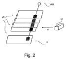
次に図2を参照すると、同図は左の部分に3次元ボリュームV2の単純化された描写を示す。説明の目的でブロックV2の4つのスライスのみが示されているが、3次元ボリュームV2は通常は数十のこのようなスライスからなることが理解される。 Next, referring to FIG. 2, the figure shows a simplified depiction of the three-dimensional volume V2 in the left part. Although only four slices of block V2 are shown for illustration purposes, it is understood that the three-dimensional volume V2 usually consists of dozens of such slices.
好適な一実施形態によれば、まず、情報理論的尺度に基づいてソースブロックV1から重み関数wが計算されるが、本明細書においては他の尺度も想定される。V1では、情報コンテンツ(例えば、情報を測定するためにシャノンエントロピーが用いられ得る)が、ボリュームV1の各スライスについて画像要素(ボクセル又は局所近傍)毎に局所的にマッピングされ、それぞれの要素位置の重みに変換される。重み付け変換は適当な正規化を含んでいてもよい。いくつかの実施形態においては、所与の画像要素におけるより高い尺度(この場合、シャノン尺度)は、その要素のために高い重み付けを引き付ける。 According to one preferred embodiment, first, the weighting function w is calculated from the source block V1 based on an information-theoretic scale, but other scales are also envisioned herein. In V1, information content (eg, Shannon entropy can be used to measure information) is locally mapped for each image element (voxel or local neighborhood) for each slice of volume V1 and at each element position. Converted to weights. The weighted transformation may include appropriate normalization. In some embodiments, a higher scale in a given image element (in this case, the Shannon scale) attracts higher weights for that element.
重み関数wを定義する際に、V1において十分に小さい近傍領域(例えば、非制限的な一例として、2×2mm2。図2には図示しない)を選択することは、より小さな特徴ならびにより大きな組織構造のエッジが考慮されることを保証する。本明細書において提案される方法は、V1において情報尺度(及びひいては重み関数w)を事前計算すること及び補間スキームを適用することによって効率的に実行され得る。より正確には、重み関数はまず、各x−y平面の2×2mm2の重複領域におけるシャノンエントロピーを計算することによって、V1の粗いグリッドについて計算される。画像ブロックV2のサンプリングを一致させるため、重み関数はまず、あるグリッドについて画像ブロックV2のサンプリングで補間され、次いでz座標に沿って正規化される。このようにして、正規化され再サンプリングされた重み関数が得られる。次に、図2の左の部分を見ると、各々が仮想x線投影源VXRから合成投影画像の1つの画素への経路を示す多数の仮想x線(図2には1つのみを示す)を用いたトモシンセシスボリュームV2全体の順方向投影によって、合成マンモグラムSが生成される。各仮想投影放射線は、ボリュームV2のすべてのスライスと交差する。この特定の放射線に沿った順方向投影を計算する前に、各交差点は、正規化され再サンプリングされた重み関数の対応する値で乗算される。 When defining the weighting function w, selecting a sufficiently small neighborhood region in V1 (eg, 2 × 2 mm 2 as a non-limiting example; not shown in FIG. 2) has smaller features as well as larger Ensure that the edges of the organizational structure are taken into account. The method proposed herein can be performed efficiently by precomputing the information scale (and thus the weighting function w) in V1 and applying an interpolation scheme. More precisely, the weighting function is first calculated for the coarse grid of V1 by first calculating the Shannon entropy in the 2 × 2 mm 2 overlapping region of each xy plane. To match the sampling of image block V2, the weighting function is first interpolated with the sampling of image block V2 for a grid and then normalized along the z coordinate. In this way, a normalized and resampled weighting function is obtained. Next, looking at the left part of FIG. 2, a large number of virtual x-rays, each showing a path from the virtual x-ray projection source VXR to one pixel of the composite projected image (only one is shown in FIG. 2). Synthetic mammogram S is generated by forward projection of the entire tomosynthesis volume V2 using. Each virtual projected radiation intersects all slices of volume V2. Before calculating the forward projection along this particular radiation, each intersection is multiplied by the corresponding value of the normalized and resampled weighting function.
特定の一実施形態においては、重み関数は最大エントロピー値として定義されるので、(各近傍において)最も高い情報コンテンツを有するスライス(図2では上から3番目のスライス)の画素のみが選択され、投影放射線毎の合成マンモグラムの計算に用いられる。 In one particular embodiment, the weighting function is defined as the maximum entropy value, so that only the pixels of the slice with the highest information content (in each neighborhood) (third slice from the top in FIG. 2) are selected. It is used to calculate the synthetic mammogram for each projected radiation.
このアプローチは、例えばV2にわたるビューSがモニタMTのような観察デバイスでの表示を目的とするものであるとき、確実且つ効率的な読出しワークフローのために、3次元トモシンセシスボリュームV1からのすべての関連する情報がブロックV2の2次元合成ビューSへと伝播されることを保証する。 This approach is all related from the 3D tomosynthesis volume V1 for a reliable and efficient read workflow, for example when the view S over V2 is intended for display on an observation device such as a monitor MT. It guarantees that the information to be propagated to the two-dimensional composite view S of the block V2.
図2の例においては、合成マンモグラムSは、2つの主方向CC,MLOのうちいずれか一方に沿ったz軸にたまたま平行である投影方向について計算される。zに沿って投影するとき、関連する計算は特に単純になる。なぜなら、主な画像取得(z)軸に平行でない他の方向についての場合に必要とされるような補間が不要であるためである。例えば、等方性磁気共鳴画像(MRI)のように、ボリュームが好適な方向を有さないという文脈の一実施形態においては、他の投影方向も想定され且つユーザ調整可能である。 In the example of FIG. 2, the synthetic mammogram S is calculated for a projection direction that happens to be parallel to the z-axis along one of the two main directions CC and MLO. When projecting along z, the associated calculations are particularly simple. This is because there is no need for interpolation as is required for other directions that are not parallel to the main image acquisition (z) axis. For example, in one embodiment in the context of volume not having a suitable orientation, such as isotropic magnetic resonance imaging (MRI), other projection orientations are also envisioned and user adjustable.
合成マンモグラムSは、提案される方法によれば、重み付け投影を3次元重み付けボリュームV2に適用することによって、再構成された3次元ボリュームV2の3次元重み付け平均から計算され、ここで、重み関数は、重みファインダWFによって異なるブロックV1から計算される。これは、形式的には、i)ボリュームV2内における3次元ボクセル位置r、ii)空間的に適応可能な3次元重み関数w(r)を用いて、以下の方程式にまとめることができる。

一実施形態においては、各投影線上のボクセル値間の相対関係が保存されることを保証する正規化(これは1/FP(w(r))による乗算である)も存在する。この正規化は、各投影線に沿った相対的規模を尊重すなわち保存する。正規化は各投影線について別個に行われてもよく、正規化された重みによって各投影線に沿った統一性が得られる。 In one embodiment, there is also a normalization (which is multiplication by 1 / FP (w (r))) that ensures that the relative relationships between voxel values on each projection line are preserved. This normalization respects or preserves the relative scale along each projection line. Normalization may be done separately for each projection line, and the normalized weights provide uniformity along each projection line.
動作
次に、図3のフローチャートを参照して、ビューシンセサイザVSの動作をより詳細に説明する。
Operation Next, the operation of the view synthesizer VS will be described in more detail with reference to the flowchart of FIG.
ステップS305において、重み付け順方向投影において用いられる重み関数wが、上記で紹介された重み関数ファインダWFによって計算される。重み関数は第1の3次元画像ボリュームV1から計算される。これは、一実施形態においては、適当な画像構造尺度eを用いることによって行われる。一実施形態においては、(例えばシャノンエントロピーなどのエントロピー尺度を有する)情報コンテンツが各ボクセルの局所近傍で計算される。一実施形態においては、これは以下のように実行される:e(r)を、3次元トモシンセシスボリュームV1内のすべてのボクセル位置r又は近傍U(r)について定義された適当な画像構造尺度とする。想定される画像構造は、シャノンエントロピー(又は他の情報理論的尺度)の他に、ソーベルの演算子又はキャニーのエッジ検出器又は類似のフィルタに基づくエッジ尺度を含む。構造尺度eの応答は、一般的に、ボリュームV1において定量化することが望まれる情報コンテンツに「比例する」(又は少なくともそれに直接的に応じて変化する)。次に、w(r)=f[e(r)]を局所的重みとする。ただし、f[.]は重みを「整形する」ための関数である。換言すれば、実際の尺度eの応答は、適当なスケールにマッピングされるので、所望の形態で重みとして用いられ得る。例えば、重みが単位区画内にあるとき又は大きな応答が小さな若しくは大きな重みを引き付けるときなどは、重みとして整数のみを有することが望まれるかもしれない。一実施形態によれば、重み整形部(weight shaper)fは恒等関数であるため、フィルタ応答自体が重みとして用いられるが、これが可能であるか否かは重みファインダWFの数値範囲に依存する。 In step S305, the weighting function w used in the weighted forward projection is calculated by the weighting function finder WF introduced above. The weighting function is calculated from the first 3D image volume V1. This is done in one embodiment by using an appropriate image structure scale e. In one embodiment, information content (having an entropy scale, such as Shannon entropy) is calculated in the local neighborhood of each voxel. In one embodiment, this is performed as follows: e (r) with a suitable image structure scale defined for all voxel positions r or neighborhood U (r) within the 3D tomosynthesis volume V1. To do. Assumed image structures include Shannon entropy (or other information-theoretic scales) as well as edge scales based on Sobel's operators or Canny's edge detectors or similar filters. The response of the structural scale e is generally "proportional" (or at least directly corresponding to) the information content desired to be quantified in volume V1. Next, let w (r) = f [e (r)] be the local weight. However, f [. ] Is a function for "shaping" weights. In other words, the response of the actual scale e is mapped to the appropriate scale and can be used as a weight in the desired form. For example, when the weights are within a unit partition, or when a large response attracts small or large weights, it may be desirable to have only integers as weights. According to one embodiment, since the weight shaper f is an identity function, the filter response itself is used as the weight, but whether or not this is possible depends on the numerical range of the weight finder WF. ..
一実施形態においては、ソースボリュームは、例示目的で上記図中で説明された投影データから再構成された(トモシンセシス)ボリュームである。好適な一実施形態においては、投影データは、エネルギ分解・光子計数検出器ユニットを備えた分光トモシンセシスシステムで取得される。好適には、投影データの取得の際には、(従来のマンモグラフィにおけるよりも低い)比較的低い線量が用いられる。より具体的には、一実施形態においては、ソースボリュームV1は、分光光子計数投影データに基づく物質分解によって得られる。特に、画像は、分光マンモグラフィから既知の乳腺率画像(glandularity image)であってもよい。 In one embodiment, the source volume is a (tomosynthesis) volume reconstructed from the projection data described in the figure above for illustrative purposes. In one preferred embodiment, the projection data is acquired in a spectroscopic tomosynthesis system equipped with an energy resolution / photon counting detector unit. Preferably, relatively low doses (lower than in traditional mammography) are used when acquiring projection data. More specifically, in one embodiment, the source volume V1 is obtained by material decomposition based on spectrophoton counting projection data. In particular, the image may be a mammary gland ratio image known from spectroscopic mammography.
ステップS310において、合成投影のために(ユーザ調整可能又はプロトコル調整可能な)所望の順投影方向が与えられる場合、投影画像S(合成マンモグラムなど)は、重み関数を(構造プール画像ボリュームV1とは異なる)別の画像ボリュームV2に適用すること及び再構成ボリュームV2全体の重み付け順方向投影を計算することによって計算される。 In step S310, if a desired forward projection direction (user-adjustable or protocol-adjustable) is given for composite projection, the projected image S (such as a composite mammogram) has a weighting function (with structure pool image volume V1). Calculated by applying to another (different) image volume V2 and calculating the weighted forward projection of the entire reconstructed volume V2.
一実施形態においては、ボリュームV2は、別の再構成されたトモシンセシスボリュームである。一実施形態においては、他の再構成されたボリュームV2は、エネルギ加重された分光投影データから算出された、再構成されたボリュームである。一実施形態においては、V1及びV2はそれぞれ、光子計数撮像又は二重エネルギ撮像で得られた高エネルギ画像と低エネルギ画像との異なる線形結合である。 In one embodiment, volume V2 is another reconstructed tomosynthesis volume. In one embodiment, the other reconstructed volume V2 is a reconstructed volume calculated from energy-weighted spectroscopic projection data. In one embodiment, V1 and V2 are different linear combinations of high energy and low energy images obtained by photon counting imaging or dual energy imaging, respectively.
また、上記からは、構造的尺度の実際の計算はステップS305においてソースブロックV1についてのみ算出されて、重みが導出されることが察知されるであろう。構造尺度の計算は、一旦V1を介して重みが得られれば、V2についてはもはや不要である。V2においては、この重みのみを用いて順方向投影を計算する。これは、効率的な計算の実行を可能にする。 Also, from the above, it will be detected that the actual calculation of the structural scale is calculated only for the source block V1 in step S305, and the weight is derived. The calculation of the structural scale is no longer necessary for V2 once the weights are obtained via V1. In V2, the forward projection is calculated using only this weight. This allows for efficient calculation execution.
その後、一実施形態においては、ステップS310の(順方向投影部FPによって実行される)重み付け順方向投影において、(ソースブロックV1からの重み関数wによって記録された)各ボリュームボクセルの重みが、投影点FP1の値の計算におけるそのボリュームボクセル値の相対的な「寄与」を判定する。次に、合成マンモグラムSが、上記の方程式(1)に従って、重み付け投影として計算され得る。一実施形態によれば、マンモグラフィのために用いられるとき、順方向投影は、2つの主な画像取得方向CC,MLOのうちいずれか一方に沿って動作するであろう。換言すれば、順方向投影は、補間を回避するために、トモシンセシススライスに直角に動作するであろう。このとき、トモシンセシス・アーチファクトがグリッドと整列するように、ジオメトリを一致させたグリッド又は以前のボリューム再構築のための座標系を使用するのが合理的である。これは、X線コーンビームの拡大効果が補償されるようにスライスの各々を効果的に再スケーリングすることに相当する。 Then, in one embodiment, in the weighted forward projection (executed by the forward projection unit FP) in step S310, the weight of each volume voxel (recorded by the weight function w from the source block V1) is projected. Determine the relative "contribution" of the volume voxel value in the calculation of the value of point FP1. The synthetic mammogram S can then be calculated as a weighted projection according to equation (1) above. According to one embodiment, when used for mammography, forward projection will operate along one of the two main image acquisition directions CC, MLO. In other words, forward projection will operate at right angles to the tomosynthesis slice to avoid interpolation. At this time, it is reasonable to use a geometry-matched grid or a coordinate system for previous volume reconstruction so that the tomosynthesis artifacts are aligned with the grid. This corresponds to effectively rescaling each of the slices so that the magnifying effect of the X-ray cone beam is compensated.
そのような場合、方程式(1)は
![]()
![]()
他の実施形態においては、重み関数は、各投影方向に沿って最も高い尺度値(例えばシャノン尺度値)を有するスライスの画像要素には重み「1」を割り当て、その一方で残りのスライスの放射線に沿ったすべての画像要素は重みゼロを引き付ける。換言すれば、重み関数はバイナリ指示関数であり、投影画像Sの目標投影点に寄与するのは最も高い尺度を有する画像要素のみである。 In other embodiments, the weighting function assigns a weight of "1" to the image element of the slice with the highest scale value (eg Shannon scale value) along each projection direction, while the radiation of the remaining slices. All image elements along are attracting zero weight. In other words, the weighting function is a binary indicator function, and it is only the image element with the highest scale that contributes to the target projection point of the projected image S.
ステップS320において、合成投影画像Sは出力ポートOUTを介して出力される。投影画像Sはその後、表示ユニットMでの表示のためにレンダリングされ、又はデータベースに記憶され、又は画像処理されてもよい。 In step S320, the composite projection image S is output via the output port OUT. The projected image S may then be rendered for display on the display unit M, stored in a database, or image processed.
戻って上記で言及した分光撮像の実施形態を参照すると、エネルギ分解された(分光)トモシンセシス投影データは、衝突する光子をエネルギ分解検出器により高エネルギビン(分類)と低エネルギビン(分類)とに分けることによって取得される。このようにすれば、分光トモシンセシス投影データはその後、物質分解及び組織特異的画像の計算に使用可能であり、一実施形態においては構造プール画像V1が再構成される。例えば、V1は、分光画像データに基づく物質分解から得られる脂肪及び/又は腺画像ならびに画像対象BR(乳房はほんの一例である)の物質組成のモデルへと再構成されてもよい。別の一実施形態においては、V1は、代数的再構成技術(ART)のファミリーのトモシンセシス再構成アルゴリズムによって、乳房密度(「乳腺率」)画像及び/又は「乳房厚さ」画像へと再構成されてもよい。さらに、一実施形態においては、分光投影データはエネルギ重み付けによって処理されてもよく、一実施形態においてはそこから、観察デバイス上での表示に有益なトモシンセシスボリュームデータセットV2が再構成される。本発明の方法の分光画像データ(及びそのようなデータから得られる画像)への適用に関するマンモグラフィの例は単なる一例に過ぎず、本明細書においては、他の物質分解及び/又は撮像される器官BR若しくは対象BRへの適用も同様に想定されることが理解されるべきである。 Returning to the spectroscopic imaging embodiment mentioned above, the energy-decomposed (spectroscopic) tomosynthesis projection data classifies colliding photons into high energy bins (classification) and low energy bins (classification) by an energy degradation detector. Obtained by dividing into. In this way, the spectroscopic tomosynthesis projection data can then be used for material degradation and tissue-specific image calculations, and in one embodiment the structural pool image V1 is reconstructed. For example, V1 may be reconstructed into a model of the material composition of fat and / or glandular images obtained from material degradation based on spectroscopic image data and the image subject BR (breast is just one example). In another embodiment, V1 is reconstructed into a breast cancer (“breast ratio”) image and / or a “breast thickness” image by a family of algebraic reconstruction techniques (ART) tomosynthesis reconstruction algorithms. May be done. Further, in one embodiment, the spectroscopic projection data may be processed by energy weighting, from which the tomosynthesis volume dataset V2, which is useful for display on the observation device, is reconstructed. The examples of mammography relating to the application of the methods of the invention to spectroscopic image data (and images obtained from such data) are merely examples, and in the present specification, other substances decomposed and / or organs to be imaged. It should be understood that application to BR or target BR is expected as well.
好適な一実施形態においては、エントロピーベースの重み関数は乳房密度画像V1からのみ計算され、この重み関数はその後、エネルギ重み付け投影データのトモシンセシス再構成ボリュームV2にわたる重み付け順方向投影において適用される。 In one preferred embodiment, the entropy-based weighting function is calculated only from the breast cancer image V1 and this weighting function is then applied in the weighted forward projection over the tomosynthesis reconstructed volume V2 of the energy weighted projection data.
この実施形態においては、重み関数は正規化されたシャノンエントロピー尺度によって定義され、これは乳房密度画像V1の各ボクセルにおいて、長方形の窓によって定義される局所近傍で計算される。正規化は、順方向投影における各放射線に沿った重みの総和によって統一性が得られることを保証する。正規化に先立って、重み関数は局所的にフィルタ処理及び/又は閾値処理されてもよい。例えば、重み関数は、最初に小領域に細分化され得る。次に、小領域の各々について、特定の閾値を下回るすべてのボクセルがゼロに設定され、その閾値を上回るボクセルが1という重みを割り当てられる。この実施形態においては、この関数を次に、例えばガウシアンフィルタカーネルで平滑化すること、及び各小領域において正規化することによって、重み関数が得られる。この正規化されたシャノンエントロピーベースの尺度は、乳房密度画像又はエネルギ重み付け投影データからのトモシンセシス再構成ボリュームの他に、ボリュームV1,V2についての使用も想定される。 In this embodiment, the weighting function is defined by a normalized Shannon entropy scale, which is calculated in each voxel of the breast cancer image V1 in the local vicinity defined by the rectangular window. Normalization ensures that uniformity is achieved by the sum of the weights along each radiation in the forward projection. Prior to normalization, the weighting function may be locally filtered and / or thresholded. For example, the weighting function can first be subdivided into smaller regions. Next, for each of the small regions, all voxels below a certain threshold are set to zero, and voxels above that threshold are assigned a weight of 1. In this embodiment, the weighting function is then obtained by smoothing this function, for example with a Gaussian filter kernel, and normalizing in each subregion. This normalized Shannon entropy-based scale is expected to be used for volumes V1 and V2 as well as tomosynthesis reconstructed volumes from breast cancer image or energy weighted projection data.
一実施形態においては、ステップ305における重み関数の計算は、多解像度アプローチによって達成される。この多解像度アプローチは、本明細書に記載のすべての実施形態と組み合わせ可能である。
In one embodiment, the calculation of the weighting function in
一実施形態においては、多解像度アプローチは、前述したシャノンエントロピー尺度を計算することによって実現可能であるが、固定的な大きさの窓/カーネルを用いる代わりに、シャノンエントロピー尺度は、大きさが増していく多数の長方形の窓/カーネルで計算される。すると、窓/カーネルの大きさよって定義された各解像度レベルにつき1つの重み関数という様々な重み関数のファミリーが得られる。 In one embodiment, the multi-resolution approach can be achieved by calculating the Shannon entropy scale described above, but instead of using a fixed size window / kernel, the Shannon entropy scale is increased in size. Calculated with a large number of rectangular windows / kernels. This yields a family of various weighting functions, one for each resolution level defined by the size of the window / kernel.
この様々な重み関数のセットは、その後、これらの重み関数を加算及び正規化することによって結合されて1つの最終的な重み付け関数となり、画像V2に適用される。 This set of various weighting functions is then combined by adding and normalizing these weighting functions into one final weighting function, which is applied to image V2.
別の一実施形態においては、ガウス・ラプラスピラミッド分解又はウェーブレット解析など、当該技術分野において既知の方法に基づいた画像V1及び画像V2の多解像度分解が用いられる。画像は、概して、ハイパス成分と、様々なローパス及びバンドパス成分とに分解される。重み関数は、V1について分解の各レベルで計算され、その後トモシンセシスボリュームV2の対応する分解のレベルに適用される。 In another embodiment, multi-resolution decomposition of images V1 and V2 based on methods known in the art, such as Gauss-Laplace pyramid decomposition or wavelet analysis, is used. The image is generally decomposed into a high-pass component and various low-pass and band-pass components. The weighting function is calculated for each level of decomposition for V1 and then applied to the corresponding level of decomposition for tomosynthesis volume V2.
一実施形態においては、多解像度分解の異なるスケールにおける重み関数を計算するために用いられる尺度は、前記のスケール/レベルに依存する。例えば、一実施形態においては、特定の閾値周波数を下回る低周波数画像成分については上述したシャノンエントロピーベースの重み関数が計算され、画像の高周波数部分に関しては最大輝度尺度などの異なる尺度が用いられる。 In one embodiment, the scale used to calculate the weighting function at different scales of the multiresolution resolution depends on the scale / level described above. For example, in one embodiment, the Shannon entropy-based weighting function described above is calculated for low frequency image components below a particular threshold frequency, and different scales such as the maximum luminance scale are used for the high frequency portion of the image.
さらなる精緻化として、一実施形態においては、標準的な平均化投影の低空間周波数がエントロピー重み付け合成マンモグラムSの低周波数コンテンツと合併して、従来の2次元マンモグラムの典型的な背景の外観が得られる。 As a further refinement, in one embodiment, the low spatial frequencies of the standard averaging projection merge with the low frequency content of the entropy-weighted synthetic mammogram S to give the typical background appearance of a traditional 2D mammogram. Be done.
上述のように、シャノンエントロピー尺度は、重み関数を定義するための一例に過ぎない。重み定義のための尺度の他の実施形態は、(キャニー又はソーベルの演算子によって実行される)エッジ尺度である。 As mentioned above, the Shannon entropy scale is just one example for defining a weighting function. Another embodiment of the scale for weight definition is the edge scale (performed by the Canny or Sobel operator).
さらに他の実施形態においては、重みファインダWFはCAD(コンピュータ支援設計)画像特徴検出器を含む。CADにおいては、動作は、様々な種類の病変についての様々な大きさ又は様々な形状や石灰化の度合いなどの特徴又はテンプレートのライブラリに、又は、マンモグラフィ以外の文脈においては、血管又は脳の構造などといった特定の関心器官の形状フットプリント(shape footprints)に基づく。CAD検出器は、ボリュームTを走査し、前記の形状テンプレートに一致するボクセルを検出する。一致したボクセルは、病変有棘塊状物などを示す疑わしい形状を構成し得る。ユーザ定義可能な信頼レベルと対比して測定すると、所与のボクセルがそのような疑わしい形状構造の一部を形成するか否かが決定される。所与のボクセルの信頼度に応じて、重みが割り当てられる。高い信頼は高い重みを引き付け、低い信頼は対応して低い重みを引き付けるであろう。 In yet another embodiment, the weight finder WF includes a CAD (Computer Aided Design) image feature detector. In CAD, movement is in a library of features or templates such as different sizes or shapes and degrees of calcification for different types of lesions, or in contexts other than mammography, vascular or brain structures. Based on the shape footprints of a particular organ of interest, such as. The CAD detector scans the volume T to detect voxels that match the shape template. Matched voxels can form suspicious shapes, such as lesioned spinous masses. Measured against a user-definable confidence level, it is determined whether a given voxel forms part of such a suspicious shape structure. Weights are assigned according to the confidence of a given voxel. High confidence will attract high weights, and low confidence will correspondingly attract low weights.
重み関数ファインダの実施形態のいくつか(ソーベルの演算子又はCAD検出器など)は、ボクセル近傍で動作する。一実施形態によれば、(例えば差し渡し(across)のボクセル単位で測定される)近傍の大きさは、ユーザ相互作用によって調整可能である。例えば、一実施形態においては、フィルタモジュールFLが動作する近傍の大きさをユーザが調整することを可能にするグラフィカルユーザインタフェースが想定される。いくつかの実施形態においては、テキストベースの入力手段も同様に想定される。ボクセル近傍の大きさの調整は、各々が異なる近傍の大きさを必要とする異なるフィルタモジュールと界接するときの柔軟性の度合いを高める。この実施形態においては、ステップS305で、近傍のうち少なくとも1つの大きさの仕様が受信され、近傍はそれに従って大きさ変更される。 Some embodiments of the weighting function finder (such as Sobel operators or CAD detectors) operate near voxels. According to one embodiment, the size of the neighborhood (eg, measured in voxel units of axes) is adjustable by user interaction. For example, in one embodiment, a graphical user interface is envisioned that allows the user to adjust the size of the neighborhood in which the filter module FL operates. In some embodiments, text-based input means are envisioned as well. Adjusting the size of the voxel neighborhood increases the degree of flexibility when bordering with different filter modules, each of which requires a different neighborhood size. In this embodiment, in step S305, a specification of at least one size of the neighborhood is received and the neighborhood is resized accordingly.
上述した多解像度の実施形態においては、CADベースの技術との組み合わせが有用であり得る。わずか数画素しか含まない非常に小さな構造(例えば微小石灰化)は、局所近傍のエントロピーにはほとんど寄与し得ず、最大エントロピー投影においては失われ得る。したがって、そのような構造を回復するために、高空間周波数のみで動作するCADベースの石灰化検出が適用可能である。しかしながら、一般的には、本明細書において提案される方法は、CAD検出に頼らずに良好に機能することがわかっている。 In the multi-resolution embodiments described above, combinations with CAD-based techniques may be useful. Very small structures (eg, microcalcifications) containing only a few pixels can make little contribution to local entropy and can be lost in maximum entropy projections. Therefore, CAD-based calcification detection, which operates only at high spatial frequencies, is applicable to restore such structures. However, in general, the methods proposed herein have been found to work well without relying on CAD detection.
好適な一実施形態においては、重み関数ファインダWFは情報コンテンツ重みを実質的にボリュームV1のすべてのボクセルに割り当てるように作用するが、そうではない実施形態も想定される。例えば、一実施形態においては、ユーザはサブボリュームを指定することができ、それに沿って順方向投影が行われる。こうしたボリューム制限は、CPU時間を節約することを可能にするであろう。この実施形態においては、ユーザが、例えば3次元ボリュームTが表示されるグラフィカルユーザインタフェースでのタッチスクリーン又はポインタツールのアクションによって、「投影窓」(若しくは視界FoV)又は投影目的のスライスのサブセットを指定することが想定される。図2ではこれが破線の円で示されているが、投影窓FoVは、正方形又は長方形など、任意の所望の形状をとり得る。その場合、投影線は、そのように指定されたサブボリュームのみを横切って投げかけられる。 In one preferred embodiment, the weighting function Finder WF acts to assign information content weights to virtually all voxels in volume V1, but other embodiments are envisioned. For example, in one embodiment, the user can specify a subvolume along which forward projection is performed. Such volume limits would make it possible to save CPU time. In this embodiment, the user specifies a "projection window" (or field of view FoV) or a subset of slices for projection purposes, for example by the action of a touch screen or pointer tool in a graphical user interface where a 3D volume T is displayed. It is expected to do. Although this is indicated by a dashed circle in FIG. 2, the projection window FoV can take any desired shape, such as a square or a rectangle. In that case, the projection line is cast only across the subvolumes so designated.
さらに別の一実施形態によれば、CPU時間を節約するために、ビューシンセサイザVSは、アンダーサンプリングアルゴリズムを用いることによって3次元ボリュームを「粗くする」機能をユーザに与える。隣接するボクセルは新たな、より粗い画像要素にまとめられ、ボリュームV1,V2はそれらの画像要素に分割される。換言すれば、3次元ボリュームは大きさが縮小されるので、方程式(2)における総和はより少ない項にわたり、より少ない重みが計算を要するようになる。 According to yet another embodiment, in order to save CPU time, the view synthesizer VS provides the user with the ability to "coarse" the 3D volume by using an undersampling algorithm. Adjacent voxels are grouped into new, coarser image elements, and volumes V1 and V2 are divided into those image elements. In other words, since the 3D volume is reduced in size, the sum in equation (2) spans fewer terms and requires less weight to be calculated.
一実施形態においては、各ボクセルにおける勾配の計算は、時間勾配成分も含む。これは、投影画像が動的3次元ボリュームについて、すなわち4次元ボリュームとも称される3次元ボリュームの時系列について合成されるときに、特に関連がある。時間勾配のため、時間によって異なる3次元ボリューム間で大きく変化する画像部分は高い重みを引き付ける。この実施形態では、合成投影画像は、ユーザが発展、つまり所望の投影方向に沿った投影図の3次元ボリューム間の構造の経時的な変化を観察することを可能にする。 In one embodiment, the gradient calculation for each voxel also includes a time gradient component. This is especially relevant when the projected image is synthesized for a dynamic 3D volume, i.e. for a time series of 3D volumes, also called 4D volumes. Due to the time gradient, image parts that vary significantly between three-dimensional volumes that vary with time attract high weights. In this embodiment, the composite projection image allows the user to observe the evolution, i.e., the change in structure between the three-dimensional volumes of the projection along the desired projection direction over time.
例えば、心臓撮像では、閉じた円形の経路に関して円形のトモシンセシスが用いられる。「スライディングウィンドウ」技術では、再構成されたボリュームV2tの時系列が再構成され、これらが順方向投影されて、対応する一連の2次元ビューSを生成することができる。これは、カテーテル処置室での適用において蛍光透視をシミュレーションするために使用可能である。この実施形態においてもやはり、V1,V2画像ボリューム対は、分光円形トモシンセシスにおいて得られる高及び低エネルギ画像によって与えられ得る。 For example, cardiac imaging uses circular tomosynthesis with respect to a closed circular pathway. In the "sliding window" technique, the time series of the reconstructed volume V2 t can be reconstructed and projected forward to generate a corresponding series of 2D views S. It can be used to simulate fluoroscopy in applications in the catheterization room. Again in this embodiment, the V1, V2 image volume pairs can be provided by the high and low energy images obtained in spectroscopic circular tomosynthesis.
一実施形態においては、第1のモダリティIM1(例えばMIS)は、位相コントラスト撮像のための干渉計格子を含んでいてもよく、V2は位相コントラスト又は吸収信号のための画像情報を含んでいてもよく、ソースボリュームV1は暗視野信号から形成される。 In one embodiment, the first modality IM1 (eg, MIS) may include an interferometer grid for phase contrast imaging, and V2 may include image information for phase contrast or absorption signals. Often, the source volume V1 is formed from a darkfield signal.
いくつかの実施形態においては、異なる画像ブロックV1iから計算された複数の重み関数が存在していてもよく、その場合ユーザは、合成投影画像S中のどの構造が強調されるのかに応じて、(どの画像ブロックV1iを形成する)どの重み関数が順方向投影に用いられるのかを、ユーザ相互作用において選択することができる。 In some embodiments, there may be multiple weighting functions calculated from different image blocks V1 i , in which case the user depends on which structure in the composite projected image S is emphasized. , Which weighting function (which forms the image block V1 i ) is used for forward projection can be selected in the user interaction.
ビューシンセサイザVSの構成要素、すなわち重み関数WF及び順方向投影部FPは、Matlab(登録商標)などの適当な科学的計算プラットフォームでプログラムされた後、ライブラリに保存されたC++又はCルーチンに翻訳され、ワークステーションWSによって呼び出されたときにリンクされる。例えば、Matlabは、SOBELの演算子モジュールによる「画像処理ツールボックス」を特徴とする。構成要素は、専用のFPGAとして、又は実配線のスタンドアロンのチップとして配置されてもよい。 The components of the view synthesizer VS, namely the weight function WF and the forward projector FP, are programmed on a suitable scientific computing platform such as Matlab® and then translated into C ++ or C routines stored in the library. , Linked when called by Workstation WS. For example, Matlab features an "image processing toolbox" with SOBEL operator modules. The components may be arranged as a dedicated FPGA or as a stand-alone chip with real wiring.
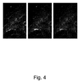
次に図4を参照すると、提案される方法と最大強度投影(MIP)との比較が示されている。トモシンセシスボリュームの選択されたスライスが示されている(左)。MIP(中央)は、すべてのスライスの関連する明るい特徴を保持している。しかしながら、高周波画像ノイズ及び実質テクスチャは当初のスライスに比べて劣化されている。提案される方法(右)は、これらの繊細な画像特徴を維持しつつ、すべての関連する特徴及びエッジも伝播している。 Next, with reference to FIG. 4, a comparison between the proposed method and maximum intensity projection (MIP) is shown. Selected slices of tomosynthesis volume are shown (left). The MIP (center) retains the associated bright features of all slices. However, high frequency image noise and real texture are degraded compared to the original slice. The proposed method (right) propagates all relevant features and edges while preserving these delicate image features.
本発明の主な用途は、デジタル乳房トモシンセシスの取得からの合成マンモグラムの生成である。この他に、3元ボリュームを提供する他の撮像モダリティもまた、高画質の仮想投影図の計算のための提案される概念から恩恵を受け得る。これは、乳房CT、胸部CT、胸部MR及び多くの他のものを含む。 The main application of the present invention is the generation of synthetic mammograms from the acquisition of digital breast tomosynthesis. In addition to this, other imaging modality that provides a ternary volume can also benefit from the proposed concept for the calculation of high quality virtual projections. This includes breast CT, chest CT, chest MR and many others.
提案される方法は、特にシャノンエントロピー尺度が使用されるときに組み合わせて、以下の重要な利点を有する。:関連する情報が、何ら特徴の検出及び高周波数ノイズ(すなわち信号対ノイズ比(SNR)及びノイズパワースペクトル)を要さずに、効率的に選択され合成ビューに伝播されるとともに、スライスの実質テクスチャが保存されるので別個の画像フィルタリング及び調整が必要とされない。 The proposed method has the following important advantages, especially in combination when the Shannon entropy scale is used. : Relevant information is efficiently selected and propagated to the composite view without any feature detection and high frequency noise (ie signal-to-noise ratio (SNR) and noise power spectrum) and slice parenchyma No separate image filtering and adjustment is required as the texture is preserved.
本発明の別の例示的な一実施形態においては、適切なシステム上で前述の実施形態のうちいずれかによる方法の方法ステップを実行するように適合されていることを特徴とするコンピュータプログラム又はコンピュータプログラム要素が提供される。 In another exemplary embodiment of the invention, a computer program or computer adapted to perform a method step of the method according to any of the aforementioned embodiments on a suitable system. Program elements are provided.
したがって、コンピュータプログラム要素はコンピュータユニットに記憶されていてもよく、これも本発明の実施形態の一部であり得る。計算ユニットは、上述の方法のステップを実行するように又は実行を誘発するように適合されていてもよい。さらに、計算ユニットは、上述の装置の構成要素を動作させるように適合されていてもよい。計算ユニットは、自動的に動作するように及び/又はユーザの命令を実行するように適合され得る。コンピュータプログラムがデータプロセッサのワーキングメモリにロードされてもよい。したがって、データプロセッサは、本発明の方法を実行するように装備されていてもよい。 Therefore, computer program elements may be stored in a computer unit, which may also be part of an embodiment of the present invention. Computational units may be adapted to perform or induce execution of the steps of the method described above. In addition, the compute unit may be adapted to operate the components of the device described above. Computational units may be adapted to operate automatically and / or execute user instructions. The computer program may be loaded into the working memory of the data processor. Therefore, the data processor may be equipped to perform the methods of the invention.
本発明のこの例示的な実施形態は、まさに最初から本発明を用いるコンピュータプログラムと、更新によって既存のプログラムを本発明を用いるプログラムに変えるコンピュータプログラムとの両方をカバーする。 This exemplary embodiment of the invention covers both computer programs that use the invention from the very beginning and computer programs that are updated to transform existing programs into programs that use the invention.
さらに、コンピュータプログラム要素は、上述の方法の例示的な一実施形態の手順を満足するために必要なすべてのステップを提供することが可能であり得る。 In addition, computer program elements may be able to provide all the steps necessary to satisfy the procedure of one exemplary embodiment of the method described above.
本発明のさらなる例示的な一実施形態によれば、CD−ROMのようなコンピュータ可読媒体が提示され、このコンピュータ可読媒体はコンピュータプログラム要素を記憶しており、このコンピュータプログラム要素は前述の部分によって説明されている。 According to a further exemplary embodiment of the invention, a computer readable medium such as a CD-ROM is presented, the computer readable medium storing computer program elements, which computer program elements are by the aforementioned portion. Explained.
コンピュータプログラムは、光記憶媒体又は他のハードウェアと共に若しくはその一部として供給される固体媒体などの適当な媒体に記憶され及び/又は分配されてもよいが、インターネット又は他の有線若しくは無線通信システムを介するなど、他の形態で配信されてもよい。 Computer programs may be stored and / or distributed on a suitable medium, such as a solid medium supplied with or as part of an optical storage medium or other hardware, but the Internet or other wired or wireless communication system. It may be delivered in other forms, such as via.
しかしながら、コンピュータプログラムは、World Wide Webなどのネットワーク経由で提示されてもよく、そのようなネットワークからデータプロセッサのワーキングメモリにダウンロード可能である。本発明のさらなる例示的な一実施形態によれば、コンピュータプログラム要素をダウンロード用に利用可能にする媒体が提供され、このコンピュータプログラム要素は、本発明の前述の実施形態のうちいずれかによる方法を実施するように配置される。 However, the computer program may be presented via a network such as the World Wide Web, which can be downloaded from such a network into the working memory of the data processor. A further exemplary embodiment of the invention provides a medium that makes a computer program element available for download, the computer program element according to any of the aforementioned embodiments of the invention. Arranged to carry out.
本発明の実施形態は様々な主題を参照して記載されていることに注意しなければならない。特に、いくつかの実施形態は方法型の請求項を参照して記載されており、他の実施形態は装置型の請求項を参照して記載されている。しかしながら、当業者であれば、上記及び下記から、別段の通知がない限り、一方の型の主題に属する特徴の任意の組み合わせに加え、異なる主題に関する特徴の間の任意の組み合わせも本願によって開示されていると考えられることがわかるであろう。もっとも、すべての特徴が、組み合わされて、特徴の単なる総和を超える相乗効果を提供することが可能である。 It should be noted that embodiments of the present invention have been described with reference to various subjects. In particular, some embodiments are described with reference to method-type claims, while others are described with reference to device-type claims. However, those skilled in the art will disclose from the above and below any combination of features belonging to one type of subject, as well as any combination between features relating to a different subject, unless otherwise noted. You will find that you are considered to be. However, it is possible that all features can be combined to provide a synergistic effect that goes beyond the mere sum of the features.
本発明は図面及び前述の記載において詳細に図示され説明されているが、そのような図示及び説明は説明的又は例示的なものと考えられるべきであり、限定的なものと考えられるべきではない。本発明は開示される実施形態に限定されない。開示された実施形態の他のバリエーションは、特許請求されている発明の実施にあたり、当業者が、図面、開示内容、及び従属請求項の検討から理解及び実行可能である。 Although the present invention is illustrated and described in detail in the drawings and the aforementioned description, such illustration and description should be considered descriptive or exemplary and should not be considered limiting. .. The present invention is not limited to the disclosed embodiments. Other variations of the disclosed embodiments can be understood and implemented by those skilled in the art from the examination of drawings, disclosures, and dependent claims in the practice of the claimed invention.
請求項中、「備える(comprising)」との文言は他の要素又はステップを除外せず、要素は複数を除外しない。単一のプロセッサ又は他のユニットが、請求項内に記載されたいくつかのアイテムの機能を果たしてもよい。単にいくつかの手段が互いに異なる従属請求項に記載されているからといって、これらの手段の組み合わせを好適に使用することができないとは限らない。請求項中の如何なる参照符号も、特許請求の範囲を限定するものと解釈されるべきではない。 In the claims, the phrase "comprising" does not exclude other elements or steps, and does not exclude more than one element. A single processor or other unit may perform the function of some of the items described in the claims. Just because some means are described in different dependent claims does not mean that a combination of these means cannot be used favorably. Any reference code in the claims should not be construed as limiting the scope of the claims.
Claims (13)
断層撮像システムによって取得されたデータの第1のセットから得られる第1の画像に基づいて、シャノンエントロピー尺度、又は、キャニー若しくはソーベルの演算子によって実行されるエッジ尺度を計算することによって計算される重み関数を計算するステップと、
少なくとも、断層撮像システムによって取得されたデータの第2のセットから得られる第2の画像に基づいて、所望の投影方向に沿って前記第2の画像にわたり順方向投影を行い、投影画像を生成するステップと
を含み、
前記第1の画像は、光子計数検出器によって検出されたデータから再構成された分光画像、マルチスケール分解から得られた再構成された空間周波数成分画像のうち、いずれか1つであり、前記第2の画像は、エネルギ重み付けされた再構成された画像ボリュームであり、
前記第1又は前記第2の画像はトモシンセシスボリュームであり、前記投影画像は合成画像であり、前記順方向投影は前記重み関数によって重み付けされ、前記重み関数は、補間スキームを適用することによって、前記第2の画像のサンプリングに一致するように再サンプリングされる、画像処理方法。 An image processing method for forming a projected image.
Calculated by calculating the Shannon entropy scale, or the edge scale performed by the Canny or Sobel operator , based on the first image obtained from the first set of data acquired by the tomographic imaging system. Steps to calculate the weight function and
At a minimum, based on the second image obtained from the second set of data acquired by the tomographic imaging system, forward projection is performed over the second image along the desired projection direction to generate a projected image. Including steps
The first image is any one of a spectroscopic image reconstructed from the data detected by the photon counting detector and a reconstructed spatial frequency component image obtained from multiscale decomposition. The second image is an energy-weighted reconstructed image volume .
The first or second image is a tomosynthesis volume, the projected image is a composite image, the forward projection is weighted by the weighting function, and the weighting function is said by applying an interpolation scheme. An image processing method that is resampled to match the sampling of the second image.
A computer-readable medium in which the computer program according to claim 12 is stored.
Applications Claiming Priority (3)
| Application Number | Priority Date | Filing Date | Title |
|---|---|---|---|
| EP14194069.2 | 2014-11-20 | ||
| EP14194069 | 2014-11-20 | ||
| PCT/EP2015/076115 WO2016078958A1 (en) | 2014-11-20 | 2015-11-10 | Method for generation of synthetic mammograms from tomosynthesis data |
Publications (3)
| Publication Number | Publication Date |
|---|---|
| JP2017535344A JP2017535344A (en) | 2017-11-30 |
| JP2017535344A5 JP2017535344A5 (en) | 2018-12-20 |
| JP6766045B2 true JP6766045B2 (en) | 2020-10-07 |
Family
ID=52023170
Family Applications (1)
| Application Number | Title | Priority Date | Filing Date |
|---|---|---|---|
| JP2017526644A Active JP6766045B2 (en) | 2014-11-20 | 2015-11-10 | How to generate a synthetic mammogram from tomosynthesis data |
Country Status (5)
| Country | Link |
|---|---|
| US (1) | US10255697B2 (en) |
| EP (1) | EP3221847B1 (en) |
| JP (1) | JP6766045B2 (en) |
| CN (1) | CN107004283B (en) |
| WO (1) | WO2016078958A1 (en) |
Families Citing this family (27)
| Publication number | Priority date | Publication date | Assignee | Title |
|---|---|---|---|---|
| US10638994B2 (en) | 2002-11-27 | 2020-05-05 | Hologic, Inc. | X-ray mammography with tomosynthesis |
| WO2006058160A2 (en) | 2004-11-26 | 2006-06-01 | Hologic, Inc. | Integrated multi-mode mammography/tomosynthesis x-ray system and method |
| US7616801B2 (en) | 2002-11-27 | 2009-11-10 | Hologic, Inc. | Image handling and display in x-ray mammography and tomosynthesis |
| US10319090B2 (en) * | 2014-05-14 | 2019-06-11 | Koninklijke Philips N.V. | Acquisition-orientation-dependent features for model-based segmentation of ultrasound images |
| US10531854B2 (en) * | 2015-12-01 | 2020-01-14 | Canon Medical Systems Corporation | X-ray CT apparatus |
| US11076820B2 (en) | 2016-04-22 | 2021-08-03 | Hologic, Inc. | Tomosynthesis with shifting focal spot x-ray system using an addressable array |
| CN109195526B (en) * | 2016-06-07 | 2020-08-14 | 皇家飞利浦有限公司 | X-ray imaging system and quantitative imaging method and computing unit thereof |
| DE102016215831A1 (en) | 2016-08-23 | 2018-03-01 | Siemens Healthcare Gmbh | Automatic generation of synthetic projections |
| JP6639357B2 (en) * | 2016-08-24 | 2020-02-05 | 富士フイルム株式会社 | Image processing apparatus, method and program |
| CN109643441B (en) | 2016-08-30 | 2023-07-18 | 佳能株式会社 | Image processing apparatus, image processing method, computer-readable storage medium, and image processing system |
| CN110113996A (en) * | 2016-12-19 | 2019-08-09 | 皇家飞利浦有限公司 | System and method for dark-field imaging |
| JP6849440B2 (en) * | 2017-01-16 | 2021-03-24 | キヤノンメディカルシステムズ株式会社 | Medical image processing equipment and X-ray diagnostic equipment |
| US10559100B2 (en) * | 2017-05-22 | 2020-02-11 | Prismatic Sensors Ab | Method and devices for image reconstruction |
| EP3668404B1 (en) | 2017-08-16 | 2022-07-06 | Hologic, Inc. | Techniques for breast imaging patient motion artifact compensation |
| JP6917913B2 (en) * | 2018-01-17 | 2021-08-11 | 富士フイルム株式会社 | Image processing equipment, image processing method, and image processing program |
| EP3518182B1 (en) * | 2018-01-26 | 2022-05-18 | Siemens Healthcare GmbH | Tilted slices in dbt |
| KR102555465B1 (en) * | 2018-06-11 | 2023-07-17 | 삼성전자주식회사 | Method for generating a tomography image and x-ray imaging apparatus thereof |
| US11090017B2 (en) * | 2018-09-13 | 2021-08-17 | Hologic, Inc. | Generating synthesized projection images for 3D breast tomosynthesis or multi-mode x-ray breast imaging |
| US11244481B2 (en) * | 2018-09-14 | 2022-02-08 | Nview Medical Inc. | Multi-scale image reconstruction of three-dimensional objects |
| EP3657442B1 (en) * | 2018-11-23 | 2022-10-26 | Siemens Healthcare GmbH | Synthetic mammogramm with embossed image impression |
| US10685461B1 (en) | 2018-12-20 | 2020-06-16 | Canon Medical Systems Corporation | Apparatus and method for context-oriented iterative reconstruction for computed tomography (CT) |
| US11424037B2 (en) * | 2019-11-22 | 2022-08-23 | International Business Machines Corporation | Disease simulation in medical images |
| JP7446410B2 (en) * | 2020-03-18 | 2024-03-08 | 富士フイルム株式会社 | Image processing device, method and program |
| CN115297778A (en) * | 2020-03-18 | 2022-11-04 | 富士胶片株式会社 | Image processing apparatus, method and program |
| CN112882057B (en) * | 2021-01-19 | 2023-12-08 | 中国科学院西安光学精密机械研究所 | Photon counting non-view three-dimensional imaging super-resolution method based on interpolation |
| CN113284205B (en) * | 2021-04-23 | 2024-01-02 | 沈阳先进医疗设备技术孵化中心有限公司 | CT iterative reconstruction method and device |
| US11786191B2 (en) | 2021-05-17 | 2023-10-17 | Hologic, Inc. | Contrast-enhanced tomosynthesis with a copper filter |
Family Cites Families (28)
| Publication number | Priority date | Publication date | Assignee | Title |
|---|---|---|---|---|
| GB9611831D0 (en) | 1996-06-06 | 1996-08-07 | Agfa Gevaert Nv | A method for automatically detecting objects of a predefined size within an image |
| JP4130055B2 (en) * | 2000-08-31 | 2008-08-06 | ジーイー・メディカル・システムズ・グローバル・テクノロジー・カンパニー・エルエルシー | Addition tomographic image creation method and X-ray CT apparatus |
| US7760924B2 (en) | 2002-11-27 | 2010-07-20 | Hologic, Inc. | System and method for generating a 2D image from a tomosynthesis data set |
| US8571289B2 (en) | 2002-11-27 | 2013-10-29 | Hologic, Inc. | System and method for generating a 2D image from a tomosynthesis data set |
| US6950492B2 (en) * | 2003-06-25 | 2005-09-27 | Besson Guy M | Dynamic multi-spectral X-ray projection imaging |
| US7352885B2 (en) * | 2004-09-30 | 2008-04-01 | General Electric Company | Method and system for multi-energy tomosynthesis |
| JP2006325638A (en) * | 2005-05-23 | 2006-12-07 | Konica Minolta Medical & Graphic Inc | Method of detecting abnormal shadow candidate and medical image processing system |
| US7474727B2 (en) * | 2005-10-14 | 2009-01-06 | Siemens Aktiengesellschaft | Dynamic computed tomography method and apparatus with temporal interpolation of data in perfusion studies |
| US10008184B2 (en) | 2005-11-10 | 2018-06-26 | Hologic, Inc. | System and method for generating a 2D image using mammography and/or tomosynthesis image data |
| JP4901212B2 (en) * | 2005-12-28 | 2012-03-21 | 株式会社東芝 | Medical image processing device |
| US7515682B2 (en) * | 2006-02-02 | 2009-04-07 | General Electric Company | Method and system to generate object image slices |
| DE102006025759A1 (en) * | 2006-05-31 | 2007-12-06 | Siemens Ag | Method for image reconstruction of an object with projections and apparatus for carrying out the method |
| JP2008068032A (en) * | 2006-09-15 | 2008-03-27 | Toshiba Corp | Image display device |
| US8051386B2 (en) | 2006-12-21 | 2011-11-01 | Sectra Ab | CAD-based navigation of views of medical image data stacks or volumes |
| US8284892B2 (en) * | 2008-12-22 | 2012-10-09 | General Electric Company | System and method for image reconstruction |
| WO2010109352A1 (en) * | 2009-03-26 | 2010-09-30 | Koninklijke Philips Electronics N.V. | Method and apparatus for computed tomography image reconstruction |
| WO2011044295A2 (en) | 2009-10-07 | 2011-04-14 | Hologic, Inc. | Processing and displaying computer-aided detection information associated with breast x-ray images |
| EP2335593A1 (en) * | 2009-12-15 | 2011-06-22 | Koninklijke Philips Electronics N.V. | Computed tomography apparatus |
| US9824302B2 (en) * | 2011-03-09 | 2017-11-21 | Siemens Healthcare Gmbh | Method and system for model-based fusion of multi-modal volumetric images |
| DE102011076346B4 (en) * | 2011-05-24 | 2016-07-14 | Siemens Healthcare Gmbh | Method and computer tomography system for generating tomographic image data sets |
| EP2782505B1 (en) | 2011-11-27 | 2020-04-22 | Hologic, Inc. | System and method for generating a 2d image using mammography and/or tomosynthesis image data |
| ES2641456T3 (en) * | 2012-02-13 | 2017-11-10 | Hologic, Inc. | System and method for navigating a tomosynthesis stack using synthesized image data |
| JP5745444B2 (en) * | 2012-03-05 | 2015-07-08 | 富士フイルム株式会社 | MEDICAL IMAGE DISPLAY DEVICE, MEDICAL IMAGE DISPLAY METHOD, AND MEDICAL IMAGE DISPLAY PROGRAM |
| JP2013228896A (en) * | 2012-04-26 | 2013-11-07 | Sony Corp | Image processing device, image processing method, and program |
| DE102013211547B3 (en) * | 2013-06-19 | 2014-05-22 | Siemens Aktiengesellschaft | Method for producing tomo-synthetic X-ray image of breast of patient, involves producing difference image from synthetic projection image and projection image by subtraction, and using difference image for reconstructing X-ray image |
| EP3014577A1 (en) * | 2013-06-28 | 2016-05-04 | Koninklijke Philips N.V. | Methods for generation of edge-preserving synthetic mammograms from tomosynthesis data |
| EP3072105B1 (en) * | 2013-11-20 | 2017-05-17 | Koninklijke Philips N.V. | Processing dual energy spectral mammography images |
| US9706967B2 (en) * | 2014-03-14 | 2017-07-18 | Toshiba Medical Systems Corporation | Energy-weighted single-binning for a photon-counting detector |
-
2015
- 2015-11-10 WO PCT/EP2015/076115 patent/WO2016078958A1/en active Application Filing
- 2015-11-10 US US15/525,081 patent/US10255697B2/en active Active
- 2015-11-10 EP EP15791618.0A patent/EP3221847B1/en active Active
- 2015-11-10 JP JP2017526644A patent/JP6766045B2/en active Active
- 2015-11-10 CN CN201580062573.XA patent/CN107004283B/en active Active
Also Published As
| Publication number | Publication date |
|---|---|
| CN107004283A (en) | 2017-08-01 |
| EP3221847A1 (en) | 2017-09-27 |
| US20170316588A1 (en) | 2017-11-02 |
| EP3221847B1 (en) | 2021-01-06 |
| WO2016078958A1 (en) | 2016-05-26 |
| CN107004283B (en) | 2021-07-27 |
| JP2017535344A (en) | 2017-11-30 |
| US10255697B2 (en) | 2019-04-09 |
Similar Documents
| Publication | Publication Date | Title |
|---|---|---|
| JP6766045B2 (en) | How to generate a synthetic mammogram from tomosynthesis data | |
| JP6368779B2 (en) | A method for generating edge-preserving synthetic mammograms from tomosynthesis data | |
| US9401019B2 (en) | Imaging tomosynthesis system, in particular mammography system | |
| JP4965433B2 (en) | Cone beam CT apparatus using truncated projection and pre-acquired 3D CT image | |
| JP5138910B2 (en) | 3D CAD system and method using projected images | |
| JP6534998B2 (en) | Method and apparatus for displaying a medical image | |
| US8705690B2 (en) | Imaging method with improved display of a tissue region, imaging device, and computer program product | |
| US9613440B2 (en) | Digital breast Tomosynthesis reconstruction using adaptive voxel grid | |
| US7978886B2 (en) | System and method for anatomy based reconstruction | |
| US8611492B2 (en) | Imaging method for rotating a tissue region | |
| EP2880594B1 (en) | Systems and methods for performing segmentation and visualization of multivariate medical images | |
| US6751284B1 (en) | Method and system for tomosynthesis image enhancement using transverse filtering | |
| US9275478B2 (en) | Method, control system, and computer program for compression of digital breast tomosynthesis data | |
| EP2998936B1 (en) | Method for generating a combined projection image | |
| CN105979875B (en) | Medical imaging device, method, apparatus and computer readable medium for generating a breast parameter map | |
| JP7258744B2 (en) | spectral computed tomography fingerprinting | |
| CN107886554B (en) | Reconstruction of stream data | |
| JP2023529382A (en) | Spectral darkfield imaging | |
| WO2022018943A1 (en) | Image processing device, method, and program | |
| WO2023110518A1 (en) | Improved water map calculation in spectral x-ray |
Legal Events
| Date | Code | Title | Description |
|---|---|---|---|
| A521 | Request for written amendment filed |
Free format text: JAPANESE INTERMEDIATE CODE: A523 Effective date: 20181108 |
|
| A621 | Written request for application examination |
Free format text: JAPANESE INTERMEDIATE CODE: A621 Effective date: 20181108 |
|
| A977 | Report on retrieval |
Free format text: JAPANESE INTERMEDIATE CODE: A971007 Effective date: 20190913 |
|
| A131 | Notification of reasons for refusal |
Free format text: JAPANESE INTERMEDIATE CODE: A131 Effective date: 20191007 |
|
| A601 | Written request for extension of time |
Free format text: JAPANESE INTERMEDIATE CODE: A601 Effective date: 20191225 |
|
| A521 | Request for written amendment filed |
Free format text: JAPANESE INTERMEDIATE CODE: A523 Effective date: 20200331 |
|
| TRDD | Decision of grant or rejection written | ||
| A01 | Written decision to grant a patent or to grant a registration (utility model) |
Free format text: JAPANESE INTERMEDIATE CODE: A01 Effective date: 20200818 |
|
| A61 | First payment of annual fees (during grant procedure) |
Free format text: JAPANESE INTERMEDIATE CODE: A61 Effective date: 20200916 |
|
| R150 | Certificate of patent or registration of utility model |
Ref document number: 6766045 Country of ref document: JP Free format text: JAPANESE INTERMEDIATE CODE: R150 |