EP3314771B1 - Simplified multi-band/carrier carrier aggregation radio frequency front-end based on frequency-shifted antennas - Google Patents
Simplified multi-band/carrier carrier aggregation radio frequency front-end based on frequency-shifted antennas Download PDFInfo
- Publication number
- EP3314771B1 EP3314771B1 EP16729422.2A EP16729422A EP3314771B1 EP 3314771 B1 EP3314771 B1 EP 3314771B1 EP 16729422 A EP16729422 A EP 16729422A EP 3314771 B1 EP3314771 B1 EP 3314771B1
- Authority
- EP
- European Patent Office
- Prior art keywords
- bandwidth
- antenna
- circuit block
- filters
- frequency range
- Prior art date
- Legal status (The legal status is an assumption and is not a legal conclusion. Google has not performed a legal analysis and makes no representation as to the accuracy of the status listed.)
- Active
Links
Images


Classifications
-
- H—ELECTRICITY
- H04—ELECTRIC COMMUNICATION TECHNIQUE
- H04B—TRANSMISSION
- H04B7/00—Radio transmission systems, i.e. using radiation field
- H04B7/02—Diversity systems; Multi-antenna system, i.e. transmission or reception using multiple antennas
- H04B7/04—Diversity systems; Multi-antenna system, i.e. transmission or reception using multiple antennas using two or more spaced independent antennas
- H04B7/0413—MIMO systems
-
- H—ELECTRICITY
- H04—ELECTRIC COMMUNICATION TECHNIQUE
- H04B—TRANSMISSION
- H04B7/00—Radio transmission systems, i.e. using radiation field
- H04B7/02—Diversity systems; Multi-antenna system, i.e. transmission or reception using multiple antennas
- H04B7/12—Frequency diversity
-
- H—ELECTRICITY
- H04—ELECTRIC COMMUNICATION TECHNIQUE
- H04B—TRANSMISSION
- H04B1/00—Details of transmission systems, not covered by a single one of groups H04B3/00 - H04B13/00; Details of transmission systems not characterised by the medium used for transmission
- H04B1/38—Transceivers, i.e. devices in which transmitter and receiver form a structural unit and in which at least one part is used for functions of transmitting and receiving
- H04B1/40—Circuits
- H04B1/44—Transmit/receive switching
-
- H—ELECTRICITY
- H04—ELECTRIC COMMUNICATION TECHNIQUE
- H04L—TRANSMISSION OF DIGITAL INFORMATION, e.g. TELEGRAPHIC COMMUNICATION
- H04L5/00—Arrangements affording multiple use of the transmission path
- H04L5/0001—Arrangements for dividing the transmission path
- H04L5/0003—Two-dimensional division
- H04L5/0005—Time-frequency
- H04L5/0007—Time-frequency the frequencies being orthogonal, e.g. OFDM(A) or DMT
- H04L5/001—Time-frequency the frequencies being orthogonal, e.g. OFDM(A) or DMT the frequencies being arranged in component carriers
Definitions
- Certain aspects of the present disclosure generally relate to wireless communications and, more particularly, to a simplified multi-band/multi-carrier carrier aggregation radio frequency front-end based on multiple frequency-shifted antennas.
- Wireless communication networks are widely deployed to provide various communication services such as telephony, video, data, messaging, broadcasts, and so on.
- Such networks which are usually multiple access networks, support communications for multiple users by sharing the available network resources.
- one network may be a 3G (the third generation of mobile phone standards and technology) system, which may provide network service via any one of various 3G radio access technologies (RATs) including EVDO (Evolution-Data Optimized), 1 ⁇ RTT (1 times Radio Transmission Technology, or simply 1x), W-CDMA (Wideband Code Division Multiple Access), UMTS-TDD (Universal Mobile Telecommunications System - Time Division Duplexing), HSPA (High Speed Packet Access), GPRS (General Packet Radio Service), or EDGE (Enhanced Data rates for Global Evolution).
- RATs 3G radio access technologies
- the 3G network is a wide area cellular telephone network that evolved to incorporate high-speed internet access and video telephony, in addition to voice calls. Furthermore, a 3G network may be more established and provide larger coverage areas than other network systems.
- Such multiple access networks may also include code division multiple access (CDMA) systems, time division multiple access (TDMA) systems, frequency division multiple access (FDMA) systems, orthogonal frequency division multiple access (OFDMA) systems, single-carrier FDMA (SC-FDMA) networks, 3 rd Generation Partnership Project (3GPP) Long Term Evolution (LTE) networks, and Long Term Evolution Advanced (LTE-A) networks.
- CDMA code division multiple access
- TDMA time division multiple access
- FDMA frequency division multiple access
- OFDMA orthogonal frequency division multiple access
- SC-FDMA single-carrier FDMA
- 3GPP 3 rd Generation Partnership Project
- LTE Long Term Evolution
- LTE-A Long Term Evolution Advanced
- a wireless communication network may include a number of base stations that can support communication for a number of mobile stations.
- a mobile station may communicate with a base station (BS) via a downlink and an uplink.
- the downlink (or forward link) refers to the communication link from the base station to the mobile station
- the uplink (or reverse link) refers to the communication link from the mobile station to the base station.
- a base station may transmit data and control information on the downlink to a mobile station and/or may receive data and control information on the uplink from the mobile station.
- a wireless multiple-access communication system can simultaneously support communication for multiple wireless terminals.
- Each terminal communicates with one or more base stations via transmissions on the forward and reverse links.
- the forward link (or downlink) refers to the communication link from the base stations to the terminals
- the reverse link (or uplink) refers to the communication link from the terminals to the base stations.
- This communication link may be established via a single-in-single-out, multiple-in-single-out or a multiple-in-multiple-out (MIMO) system.
- MIMO multiple-in-multiple-out
- a MIMO system employs multiple ( N T ) transmit antennas and multiple ( N R ) receive antennas for data transmission.
- a MIMO channel formed by the N T transmit and N R receive antennas may be decomposed into N S independent channels, which are also referred to as spatial channels, where N S ⁇ min ⁇ N T , N R ⁇ .
- Each of the N S independent channels corresponds to a dimension.
- the MIMO system can provide improved performance (e.g., higher throughput and/or greater reliability) if the additional dimensionalities created by the multiple transmit and receive antennas are utilized.
- a MIMO system may support time division duplex (TDD) and/or frequency division duplex (FDD) systems.
- TDD time division duplex
- FDD frequency division duplex
- the forward and reverse link transmissions are on the same frequency region so that the reciprocity principle allows the estimation of the forward link channel from the reverse link channel. This enables the base station to extract transmit beamforming gain on the forward link when multiple antennas are available at the base station.
- FDD frequency division duplex
- forward and reverse link transmissions are on different frequency regions.
- a carrier aggregation (CA) technique based on employing multiple concurrent carriers within a band can be utilized in LTE-A systems in order to further increase the communication bandwidth.
- CA can be used for both FDD and TDD systems.
- RX receiving
- TX transmitting
- RF radio frequency
- employing special components can limit supplier diversity and lead to additional RF front-end loss in RX/TX paths.
- the existing solutions for RF front-ends that utilize the CA technique do not incorporate bands being proposed for future deployments, such as bands in the unlicensed part of the LTE spectrum.
- an apparatus e.g., a wireless device
- the first antenna interface circuit includes a first transmit (TX) filter for a first band, which may be part of a first triplexer or duplexer.
- the first TX filter filters a first radio frequency (RF) signal prior to transmission via the first antenna.
- the second antenna interface circuit includes a second TX filter for a second band, which may be part of a second triplexer or duplexer.
- the second TX filter filters a second RF signal prior to transmission via the second antenna.
- the first and second RF signals may be transmitted simultaneously on the first and second bands for carrier aggregation.
- US 2015/109977 A1 discloses a method and apparatus supporting carrier aggregation.
- the apparatus includes a first antenna configured to transmit or receive signals in both a first high frequency band and a first low frequency band and a second antenna configured to transmit or receive signals in both a second high frequency band and a second low frequency band. At least one of the first high frequency band and the second high frequency band or the first low frequency band and the second low frequency band are different frequency bands for carrier aggregation.
- the apparatus may also include a third antenna and a multiband filter.
- the third antenna may be configured to receive signals in both the first and second high frequency bands or both the first and second low frequency bands.
- the multiband filter may be configured to filter the signals received by the third antenna.
- Certain aspects of the present disclosure generally relate to using separate antennas at a radio frequency front-end (RFFE) of a wireless communication device for transmission and reception on partially overlapping bands based on carrier aggregation, for example, which may permit implementation of simpler filters in the RFFE.
- RFFE radio frequency front-end
- the first bandwidth is in the first frequency range.
- the second bandwidth may be in the second frequency range.
- the first bandwidth equals the second bandwidth.
- At least one of the first circuit block or the second circuit block supports carrier aggregation using multiple component carriers in at least one of the first bandwidth or the second bandwidth, respectively.
- the first and second bandwidths range between 1400 MHz and 2800 MHz.
- the first bandwidth includes three component carriers for the transmission.
- the first circuit block may include a triplexer configured to process the one or more first signals for the transmission based on carrier aggregation using the three component carriers.
- the second bandwidth includes three component carriers for the reception.
- the second circuit block may include a triplexer configured to process the one or more second signals for the reception based on carrier aggregation using the three component carriers.
- the apparatus further includes a third circuit block coupled to the transceiver and configured to process one or more third signals for at least one of transmission or reception over a third bandwidth via the first antenna.
- the third bandwidth having frequencies lower than frequencies of the first bandwidth.
- the apparatus further includes a fourth circuit block coupled to the transceiver and configured to process one or more fourth signals for at least one of transmission or reception over a fourth bandwidth via the second antenna.
- the fourth bandwidth having frequencies higher than frequencies of the second bandwidth.
- at least one of the third circuit block or the fourth circuit block supports carrier aggregation using multiple component carriers in at least one of the third bandwidth or the fourth bandwidth, respectively.
- the apparatus further includes a first diplexer coupled to the first antenna and configured to interface the first circuit block and the third circuit block with the first antenna and a second diplexer coupled to the second antenna and configured to interface the second circuit block and the fourth circuit block with the second antenna.
- the third bandwidth ranges between 700 MHz and 900 MHz
- the fourth bandwidth ranges between 3.4 GHz and 6 GHz.
- the third bandwidth includes two component carriers for at least one of the transmission or the reception
- the third circuit block includes a quadplexer configured to process the one or more third signals for the at least one of the transmission or the reception based on carrier aggregation using the two component carriers.
- the fourth circuit block includes one or more filters configured for at least one of transmission or reception over the fourth bandwidth and a switching circuit configured to switch, within the fourth bandwidth, the at least one of the transmission or the reception from Ultra High frequency Band (UHB)-based communication to Long Term Evolution/Unlicensed (LTEU) Time Division Duplex (TDD)-based communication.
- the fourth circuit block may further include one or more passive duplexers configured to split the LTEU TDD-based communication and the UHB-based communication over bands of the fourth bandwidth.
- the first antenna is disposed at a first side of the apparatus.
- the second antenna may be placed at a second side of the apparatus opposite the first side.
- the first antenna has the same size as the second antenna.
- the first antenna and the second antenna have different sizes (e.g., the second antenna is smaller than the first antenna).
- the apparatus further includes a third antenna configured to support communications in the first frequency range and a fourth antenna configured to support communications in the second frequency range.
- the apparatus further includes a third circuit block that replicates the first circuit block coupled to the transceiver and configured to process one or more third signals for transmission over the first bandwidth via the third antenna.
- the apparatus may also further include a fourth circuit block that replicates the second circuit block coupled to the transceiver and configured to process one or more fourth signals for reception over the second bandwidth via the fourth antenna.
- Certain aspects of the present disclosure provide a method for wireless communications.
- aspects of the present disclosure support utilizing, at a radio frequency (RF) front-end of a wireless communication device, an antenna (and associated subsystem) for communications from the wireless communication device in a first frequency range and another separate antenna (and associated subsystem) for communications in a second frequency range, wherein the second frequency range may partially overlap with the first frequency range.
- RF radio frequency
- the usage of separate antennas for communications (e.g., transmission and reception) on overlapping frequency ranges may allow implementation of simpler acoustic filters at the RF front-end compared to the case when transmission and reception on overlapping bands are performed by a common subsystem of a single antenna of the RF front-end.
- CDMA Code Division Multiple Access
- OFDM Orthogonal Frequency Division Multiplexing
- TDMA Time Division Multiple Access
- SDMA Spatial Division Multiple Access
- SC-FDMA Single Carrier Frequency Division Multiple Access
- Multiple user terminals can concurrently transmit/receive data via different (1) orthogonal code channels for CDMA, (2) time slots for TDMA, or (3) sub-bands for OFDM.
- a CDMA system may implement IS-2000, IS-95, IS-856, Wideband-CDMA (W-CDMA), or some other standards.
- An OFDM system may implement Institute of Electrical and Electronics Engineers (IEEE) 802.11, IEEE 802.16, Long Term Evolution (LTE), or some other standards.
- a TDMA system may implement GSM or some other standards. These various standards are known in the art.
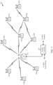
- FIG. 1 illustrates a wireless communications system 100 with access points and user terminals, in which aspects of the present disclosure may be practiced.
- An access point is generally a fixed station that communicates with the user terminals and may also be referred to as a base station (BS), an evolved Node B (eNB), or some other terminology.
- a user terminal may be fixed or mobile and may also be referred to as a mobile station (MS), an access terminal, user equipment (UE), a station (STA), a client, a wireless device, or some other terminology.
- a user terminal may be a wireless device, such as a cellular phone, a personal digital assistant (PDA), a handheld device, a wireless modem, a laptop computer, a tablet, a personal computer, etc.
- PDA personal digital assistant
- Access point 110 may communicate with one or more user terminals 120 at any given moment on the downlink and uplink.
- the downlink i.e., forward link
- the uplink i.e., reverse link
- a user terminal may also communicate peer-to-peer with another user terminal.
- a system controller 130 couples to and provides coordination and control for the access points.
- System 100 employs multiple transmit and multiple receive antennas for data transmission on the downlink and uplink.
- Access point 110 may be equipped with a number N ap of antennas to achieve transmit diversity for downlink transmissions and/or receive diversity for uplink transmissions.
- a set N u of selected user terminals 120 may receive downlink transmissions and transmit uplink transmissions.
- Each selected user terminal transmits user-specific data to and/or receives user-specific data from the access point.
- each selected user terminal may be equipped with one or multiple antennas (i.e., N ut ⁇ 1).
- the N u selected user terminals can have the same or different number of antennas.
- Wireless system 100 may be a time division duplex (TDD) system or a frequency division duplex (FDD) system.
- TDD time division duplex
- FDD frequency division duplex
- the downlink and uplink share the same frequency band.
- the downlink and uplink use different frequency bands.
- System 100 may also utilize a single carrier or multiple carriers for transmission.
- Each user terminal may be equipped with a single antenna (e.g., in order to keep costs down) or multiple antennas (e.g., where the additional cost can be supported).
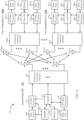
- FIG. 2 shows a block diagram of access point 110 and two user terminals 120m and 120x in wireless system 100.
- Access point 110 is equipped with N ap antennas 224a through 224ap.
- User terminal 120m is equipped with N ut,m antennas 252ma through 252mu
- user terminal 120x is equipped with N ut,x antennas 252xa through 252xu.
- Access point 110 is a transmitting entity for the downlink and a receiving entity for the uplink.
- Each user terminal 120 is a transmitting entity for the uplink and a receiving entity for the downlink.
- a “transmitting entity” is an independently operated apparatus or device capable of transmitting data via a frequency channel
- a “receiving entity” is an independently operated apparatus or device capable of receiving data via a frequency channel.
- the subscript " dn " denotes the downlink
- the subscript " up " denotes the uplink
- N up user terminals are selected for simultaneous transmission on the uplink
- N dn user terminals are selected for simultaneous transmission on the downlink
- N up may or may not be equal to N dn
- N up and N dn may be static values or can change for each scheduling interval. Beam-steering or some other spatial processing technique may be used at the access point and user terminal.
- a TX data processor 288 receives traffic data from a data source 286 and control data from a controller 280.
- TX data processor 288 processes (e.g., encodes, interleaves, and modulates) the traffic data ⁇ d up ⁇ for the user terminal based on the coding and modulation schemes associated with the rate selected for the user terminal and provides a data symbol stream ⁇ s up ⁇ for one of the N ut,m antennas.
- a transceiver front end (TX/RX) 254 receives and processes (e.g., converts to analog, amplifies, filters, and frequency upconverts) a respective symbol stream to generate an uplink signal.
- the transceiver front end 254 may also route the uplink signal to one of the N ut,m antennas for transmit diversity via an RF switch, for example.
- the controller 280 may control the routing within the transceiver front end 254.
- a number N up of user terminals may be scheduled for simultaneous transmission on the uplink.
- Each of these user terminals transmits its set of processed symbol streams on the uplink to the access point.
- N ap antennas 224a through 224ap receive the uplink signals from all N up user terminals transmitting on the uplink.
- a transceiver front end 222 may select signals received from one of the antennas 224 for processing.
- a combination of the signals received from multiple antennas 224 may be combined for enhanced receive diversity.
- the access point's transceiver front end 222 also performs processing complementary to that performed by the user terminal's transceiver front end 254 and provides a recovered uplink data symbol stream.
- the recovered uplink data symbol stream is an estimate of a data symbol stream ⁇ s up ⁇ transmitted by a user terminal.
- An RX data processor 242 processes (e.g., demodulates, deinterleaves, and decodes) the recovered uplink data symbol stream in accordance with the rate used for that stream to obtain decoded data.
- the decoded data for each user terminal may be provided to a data sink 244 for storage and/or a controller 230 for further processing.
- a TX data processor 210 receives traffic data from a data source 208 for N dn user terminals scheduled for downlink transmission, control data from a controller 230 and possibly other data from a scheduler 234. The various types of data may be sent on different transport channels. TX data processor 210 processes (e.g., encodes, interleaves, and modulates) the traffic data for each user terminal based on the rate selected for that user terminal. TX data processor 210 may provide a downlink data symbol streams for one of more of the N dn user terminals to be transmitted from one of the N ap antennas.
- the transceiver front end 222 receives and processes (e.g., converts to analog, amplifies, filters, and frequency upconverts) the symbol stream to generate a downlink signal.
- the transceiver front end 222 may also route the downlink signal to one or more of the N ap antennas 224 for transmit diversity via an RF switch, for example.
- the controller 230 may control the routing within the transceiver front end 222.
- N ut,m antennas 252 receive the downlink signals from access point 110.
- the transceiver front end 254 may select signals received from one of the antennas 252 for processing.
- a combination of the signals received from multiple antennas 252 may be combined for enhanced receive diversity.
- the user terminal's transceiver front end 254 also performs processing complementary to that performed by the access point's transceiver front end 222 and provides a recovered downlink data symbol stream.
- An RX data processor 270 processes (e.g., demodulates, deinterleaves, and decodes) the recovered downlink data symbol stream to obtain decoded data for the user terminal.
- the number of RX and TX carrier aggregation (CA) band combinations will continue to increase in current and future technologies and advancements. This may result in a more complicated radio frequency (RF) front-end of a wireless communication device (e.g., the RF front-end of the access point 110 and/or the RF front-end of the user terminal 120 from FIGs. 1-2 ), which may call for specialized acoustic filters.
- RF radio frequency
- the RF front-end may utilize a quadplexer filter in place of a duplexer filter used for a single-carrier RX/TX.
- the CA technique with three inter-band carriers may be employed. In this case, hexaplexer filters may be utilized for RX/TX in three separate bands (e.g., bands 2, 4, and 30 or bands 1, 3, and 7).
- RF front-end may limit supplier diversity and may lead to additional RF front-end loss in RX/TX paths, thus reducing sensitivity and TX power.
- existing solutions for RF front-ends that utilize the CA technique do not incorporate into the overall architecture bands being proposed for future deployments, such as bands 42/43 and bands in the unlicensed part of the LTE spectrum denoted as Long Term Evolution/Unlicensed (LTEU).
- LTEU Long Term Evolution/Unlicensed
- aspects of the present disclosure provide an RF front-end of a wireless communication device that employs two different antennas and their separate subsystems for primary communication, wherein the antennas may be frequency shifted (i.e., the antennas may have different operational bandwidths, which may partially overlap).
- two additional antennas e.g., identical to the two antennas used for primary communication
- MIMO downlink/uplink multiple-input, multiple-output
- a first antenna of an RF front-end of a wireless communication device may cover a communication bandwidth between 700 MHz and 2800 MHz.
- the first antenna (and an associated subsystem) may be configured for RX/TX over low-bands (e.g., bands between 700 MHz and 900 MHz).
- the first antenna (and the associated subsystem) may be configured for TX over mid-bands (e.g., bands between 1400 MHz and 2100 MHz) and high-bands (e.g., bands between 2300 MHz and 2800 MHz).
- a second antenna (e.g., different from the first antenna) of the RF front-end of the wireless communication device may cover a communication bandwidth between 1400 MHz and 6 GHz, i.e., the communication bandwidth that partially overlaps with the communication bandwidth of the first antenna.
- the second antenna (and an associated subsystem) may be configured for RX over mid-bands/high bands (e.g., bands between 1400 MHz and 2800 MHz).
- the second antenna (and the associated subsystem) may be configured for RX/TX over ultra-high bands and LTEU bands (e.g., bands between 3.4 GHz and 6 GHz).
- both the first and second antennas are broadband antennas capable of signal exchange in a bandwidth from 700 MHz to 6 GHz.
- aspects of the present disclosure may utilize separate antennas at the RF front-end for mid-band/high-band TX (e.g., the first antenna and its associated subsystem) and for mid-band/high-band RX (e.g., the second antenna and its associated subsystem).
- mid-band/high-band TX e.g., the first antenna and its associated subsystem
- mid-band/high-band RX e.g., the second antenna and its associated subsystem
- the approach based on separate antennas for RX and TX over mid-bands/high-bands may allow utilizing a triplexer filter instead of a hexaplexer filter, which may reduce insertion loss (IL) and implementation cost (e.g., area size and power dissipation) at the RF front-end.
- IL insertion loss
- implementation cost e.g., area size and power dissipation
- the architecture and modules associated with the first and second antennas may be replicated and used for an additional pair of antennas (e.g., secondary communication antennas) implemented at the same RF front-end.
- the secondary communication antennas identical to the primary communication antennas may be utilized for achieving antenna diversity.
- modules (subsystems) associated with the secondary antennas being identical to modules (subsystems) associated with the primary antennas of the RF front-end may be utilized for RX/TX in the case of uplink carrier aggregation.
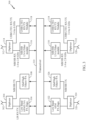
- FIG. 3 is a block diagram of an example RF front-end 300 of a wireless communication device, in accordance with certain aspects of the present disclosure.
- the wireless device with the RF front-end 300 may correspond to the access point 110 and/or the user terminal 120 from FIGs. 1-2 .
- the RF front-end 300 may comprise a transceiver 310.
- the transceiver 310 may correspond to the transceiver 222 from FIG. 2 of the access point 110, and/or to any of the transceivers 254 from FIG. 2 of the user terminals 120.
- a first antenna 302 may be configured to cover a bandwidth between 700 MHz and 2800 MHz and may be employed for low-band RX/TX and for mid-band/high-band TX. As illustrated in FIG. 3 , the first antenna 302 may be interfaced through a diplexer 304 with a module 306 and a module 308, both being connected with the transceiver 310. According to some aspects of the present disclosure, the module 306 may be configured for RX/TX over low bands (e.g., bands between 700 MHz and 900 MHz).
- the module 306 may comprise a low-band antenna switch module (ASM), one or more low-band power amplifiers (PAs) for the TX path, one or more low-noise amplifiers (LNAs) for the RX path, and a duplexer or a quadplexer filter interfacing the ASM with the PA(s) and LNA(s).
- ASM low-band antenna switch module
- PAs low-band power amplifiers
- LNAs low-noise amplifiers
- the communication filter based on the duplexer or the quadplexer may be selected depending, for example, on CA combination used for communication over the low bands.
- the module 308 may be configured for TX over mid-bands/high bands (e.g., bands between 1400 MHz and 2800 MHz).
- the module 308 may comprise a mid-band/high-band ASM, mid-band/high-band PAs, and mid-band/high-band TX filters.
- the mid-band/high-band TX filters may comprise triplexers. Thus, the usage of hexaplexers may be avoided, since the module 308 is configured for TX on mid-bands/high bands.
- the RX path over mid-bands/high bands may be implemented separately on another subsystem associated with another antenna of the RF front-end. This allows for antenna isolation to attenuate the TX signal entering the antenna on which an RX signal is being received.
- a second antenna 312 of the RF front-end 300 may be configured to cover a bandwidth between 1400 MHz and 6 GHz.
- the second antenna 312 may be employed for mid-band/high-band RX only (e.g., RX on bands between 1400 MHz and 2800 MHz).
- the second antenna 312 may be configured for ultra-high-band (UHB)-based and LTEU-based RX/TX (e.g., RX/TX over bands between 3.4 GHz and 6 GHz, such as bands 42/43 and 5 GHz WiFi band).
- UHB ultra-high-band
- LTEU-based RX/TX e.g., RX/TX over bands between 3.4 GHz and 6 GHz, such as bands 42/43 and 5 GHz WiFi band.
- the second antenna 312 may be interfaced through a diplexer 314 with a module 316 and a module 318, both being connected with the transceiver 310.
- the module 316 being placed in front of the transceiver 310 may be configured for RX over mid-bands/high bands (e.g., RX over bands between 1400 MHz and 2800 MHz).
- the module 316 may comprise a mid-band/high-band ASM, RX single-carrier, dual-carrier, or triple-carrier filters (e.g., depending on a number of RX carriers in mid-bands/high bands) and mid-band/high-band LNAs.
- the mid-band/high-band RX filters may comprise triplexers.
- the usage of hexaplexers may be avoided, since the module 316 may be configured for TX on mid-bands/high bands.
- the TX path over the mid-bands/high bands may be implemented separately on a subsystem (e.g., the module 308 interfaced with the diplexer 304) associated with the first antenna 302 of the RF front-end 300.
- the module 318 may be configured for RX/TX using UHB-based and LTEU-TDD-based communications and corresponding bands (e.g., bands between 3.4 GHz and 6 GHz).
- the module 318 may comprise an ASM, UHB/LTEU filters and switch modules (e.g., for switching from UHB-based to LTEU-TDD-based communication and vice-versa), LNAs (e.g., for RX path), and PAs (e.g., for TX path).
- the first antenna 302 may be placed on the bottom of the wireless communication device, whereas the second antenna 312 may be placed on the top of the wireless communication device.
- the first antenna 302 and the second antenna 312 may be of different sizes.
- the second antenna 312 may be smaller than the first antenna 302 due to shorter signal wavelengths processed by the second antenna 312.
- the operational bandwidth of the second antenna 312 may be substantially higher than the operational bandwidth of the first antenna 302.
- the lowest signal frequency processed by the second antenna 312 may be 1400 MHz (i.e., the second antenna processes high frequency signals with wavelengths shorter on average than wavelengths of signals being processed by the first antenna 302).
- identical antennas as the first and second antennas 302 and 312 may be employed at the RF front-end 300 for achieving communication (antenna) diversity, and/or for usage in uplink/downlink CA applications.
- a symmetric architecture may be employed at the RF front-end 300, where the aforementioned subsystems associated with the first and second (primary) antennas 302 and 312 may be also designed for an additional pair of (secondary) antennas identical to the first and second antennas.
- the two identical pairs of primary and secondary antennas at the RF front-end 300 may provide antenna diversity and downlink/uplink MIMO communication capability for the wireless communication device.
- a first secondary antenna 320 employed at the RF front-end 300 may be identical (e.g., in size and shape) to the first primary antenna 302. Hence, the first secondary antenna 320 may be also configured to cover the bandwidth between 700 MHz and 2800 MHz and may be employed for low-band RX/TX and for mid-band/high-band TX.
- a module 322 connected with the transceiver 310 and interfaced through a diplexer 324 with the first secondary antenna 320 may be identical (e.g., with respect to included components, but not necessarily with respect to layout thereof) to the module 306 interfaced with the first primary antenna 302 (e.g., the module 322 may be configured for RX/TX over low bands, such as bands between 700 MHz and 900 MHz).
- an additional module 326 connected with the transceiver 310 and interfaced through the diplexer 324 with the first secondary antenna 320 may be identical to the module 308 interfaced with the first primary antenna 302 (e.g., the module 326 may be configured for TX only over mid-bands/high-bands, such as bands between 1400 MHz and 2800 MHz).
- the modules 308 and 326 may be identical with respect to the components included, but not necessarily with respect to layout thereof.
- another (second) secondary antenna 328 employed at the RF front-end 300 may be identical (e.g., in dimensions) to the second primary antenna 312.
- the second secondary antenna 328 may be also configured to cover the bandwidth between 1400 MHz and 6 GHz.
- the second secondary antenna 328 may be used for mid-band/high-band RX (e.g., RX over bands between 1400 MHz and 2800 MHz).
- the second secondary antenna 328 may be configured for RX/TX using UHB-based and LTEU-based communications (e.g., communications over bands between 3.4 GHz and 6 GHz, such as bands 42/43 and 5GHz WiFi bands).
- a module 330 connected with the transceiver 310 and interfaced through a diplexer 332 with the second secondary antenna 328 may be identical to the module 316 interfaced with the second primary antenna 312 (e.g., the module 330 may be configured for RX over mid-bands/high bands, such as bands between 1400 MHz and 2800 MHz).
- an additional module 334 connected with the transceiver 310 and interfaced through the diplexer 332 with the second secondary antenna 328 may be identical to the module 318 interfaced with the second primary antenna 312 (e.g., the module 334 may be configured for RX/TX over UHB and LTEU bands, such as bands between 3.4 GHz and 6 GHz).
- the modules 316 and 330 (and/or the modules 318 and 334) may be identical with respect to included components, but not necessarily with respect to layout thereof.
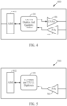
- FIG. 4 is a block diagram of an example low-band RX/TX module 400, in accordance with certain aspects of the present disclosure.
- the module 400 illustrated in FIG. 4 may correspond to the module 306 and/or to the module 322 from FIG. 3 .
- the low-band RX/TX module 400 may comprise a low-band ASM 402 (e.g., interfaced with the first primary antenna 302 or the first secondary antenna 320 from FIG. 3 ) and RX/TX duplex and/or quadplex filters 404 connected with one or more LNAs 406 (e.g., for RX path) and one or more PAs 408 (e.g., for TX path).
- LNAs 406 e.g., for RX path
- PAs 408 e.g., for TX path
- the RX/TX filters 404 may comprise a duplex filter interfaced with one LNA 406 (e.g., for RX path) and with one PA 408 (e.g., for TX path).
- the RX/TX filters 404 may comprise a quadplex filter interfaced with two LNAs 406 (e.g., for RX path) and two PAs 408 (e.g., for TX path). Therefore, the number of ports at the ASM 402 and the number of LNAs 406 and PAs 408 may be chosen based on target carriers utilized for the CA technique.
- the low-band RX/TX module 400 may utilize four ports at the ASM 402 (e.g., two ports for RX and two ports for TX), while two LNAs 406 and two PAs 408 may be employed.
- usage of different CA combinations for low-bands may determine whether a duplexer or a quadplexer should be employed for the RX/TX filters 404.
- the RX/TX filters 404 may comprise a quadplexer. If a single carrier is used for RX/TX, then a duplex filter may be employed as the RX/TX filter 404.
- FIG. 5 is a block diagram of an example mid-band/high-band TX module 500, in accordance with certain aspects of the present disclosure.
- the mid-band/high-band TX module 500 may correspond to the module 308 and/or to the module 326 from FIG. 3 .
- the mid-band/high-band TX module 500 may comprise a mid-band/high-band ASM 502 (e.g., interfaced with the first primary antenna 302 or the first secondary antenna 320 from FIG. 3 ), TX filters and TX uplink (UL) duplexers 504, and PAs 506.
- ASM 502 e.g., interfaced with the first primary antenna 302 or the first secondary antenna 320 from FIG. 3
- TX filters and TX uplink (UL) duplexers 504 e.g., TX filters and TX uplink (UL) duplexers 504, and PAs 506.
- the number of ports at the ASM 502 and the number of PAs 506 may be chosen based on target carriers utilized for the CA technique.
- the number of concurrent PAs 506 employed within the mid-band/high-band TX module 500 may be based on uplink CA specifications. For example, in the case of a three-carrier inter-band CA combination, three PAs 506 may be utilized for the concurrent transmission on three separate carriers.
- the TX filters 504 may be configured for signal transmission on mid-bands/high bands (e.g., on bands between 1400 MHz and 2800 MHz) over multiple carriers. Since RX over these bands may be separated and implemented on a different antenna subsystem (e.g., on the subsystem associated with the second antenna 312, as illustrated in FIG. 3 ), the implementation of TX filters 504 may avoid hexaplexers for a three-carrier CA combination. Instead of hexaplexers, as discussed, the TX filters 504 may utilize triplexers, which may significantly reduce implementation costs.
- mid-bands/high bands e.g., on bands between 1400 MHz and 2800 MHz
- the implementation of TX filters 504 may avoid hexaplexers for a three-carrier CA combination. Instead of hexaplexers, as discussed, the TX filters 504 may utilize triplexers, which may significantly reduce implementation costs.
- mid-band/high-band filter Frequency Division Duplex (FDD) isolation/rejection specifications may be reduced.
- FDD Frequency Division Duplex
- FIG. 6 is a block diagram of an example mid-band/high-band RX module 600, in accordance with certain aspects of the present disclosure.
- the mid-band/high-band RX module 600 may correspond to the module 316 and/or to the module 330 from FIG. 3 .
- the mid-band/high-band RX module 600 may comprise a mid-band/high-band ASM 602 (e.g., interfaced with the second primary antenna 312 or the second secondary antenna 328 from FIG. 3 ); RX single-carrier, dual-carrier, or triple-carrier filters 604; and LNAs 606.
- the number of ports at the ASM 602 and the numbers of concurrent filters 604 and LNAs 606 may be determined based on CA specifications. For example, in the case of a three-carrier CA combination, triple-carrier filters 604 and three LNAs 606 may be utilized for concurrent reception.
- the RX filters 604 may be configured for signal reception on mid-bands/high bands (e.g., bands between 1400 MHz and 2800 MHz) over multiple carriers by utilizing the CA technique. Since transmission over these same bands may be implemented separately on a different antenna subsystem (e.g., on a subsystem related to the first antenna 302 from FIG. 3 and utilizing the mid-band/high-band TX module 500 from FIG. 5 ), implementation of the RX filters 604 may avoid the usage of hexaplexers for, for example, a three-carrier CA configuration. As discussed, instead of hexaplexers, the RX filters 604 may utilize triplexers (e.g., triple-carrier filters), which may significantly reduce implementation costs.
- mid-bands/high bands e.g., bands between 1400 MHz and 2800 MHz
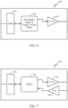
- FIG. 7 is a block diagram of an example Ultra-High-Band/High-Band (UHB/HB) RX/TX module 700, in accordance with certain aspects of the present disclosure.
- the module 700 may correspond to the module 318 and/or to the module 334 from FIG. 3 .
- the UHB/HB RX/TX module 700 may comprise an UHB/HB ASM 702 (e.g., interfaced with the second primary antenna 312 or the second secondary antenna 328 from FIG. 3 ) and RX/TX filters 704 connected with one or more LNAs 706 (e.g., for RX path) and one or more PAs 708 (e.g., for TX path).
- LNAs 706 e.g., for RX path
- PAs 708 e.g., for TX path
- the number of ports at the ASM 702, the number and type of concurrent RX/TX filters 704, and the numbers of LNAs 706 and PAs 708 may be determined based on CA specifications.
- passive diplexers may be employed as the RX/TX filters 704 to split LTEU and bands 42/43, which may provide better IL.
- FIG. 8 illustrates an example antenna placement on a wireless communication device 800 (e.g., user terminal 120 from FIG. 2 ), in accordance with certain aspects of the present disclosure.
- an antenna 802 e.g., the first primary antenna 302 from FIG. 3
- this antenna 802 may be placed, for example, at the bottom of the wireless communication device 800.
- An antenna 804 e.g., the second primary antenna 312 from FIG. 3
- this antenna 804 may be placed, for example, on the top of the wireless communication device 800.
- FIG. 8 illustrates an example antenna placement on a wireless communication device 800 (e.g., user terminal 120 from FIG. 2 ), in accordance with certain aspects of the present disclosure.
- an antenna 802 e.g., the first primary antenna 302 from FIG. 3
- An antenna 804 e.g., the second primary antenna 312 from FIG. 3
- this antenna 804 may be placed, for example, on the top of the wireless communication device 800.
- the antenna 804 (e.g., the second primary antenna 312 from FIG. 3 ) may be of a smaller size than the antenna 802 (e.g., the first primary antenna 302 from FIG. 3 ) due to shorter signal wavelengths being processed by the antenna 804.
- secondary antennas 806 and 808 identical (e.g., in configuration) to the primary antennas 802 and 804 may be employed at the wireless communication device 800.
- communication modules interfaced with the secondary antenna 806 may be identical to communication modules interfaced with the antenna 802.
- modules interfaced with the secondary antenna 808 may be identical to modules interfaced with the antenna 804.
- FIG. 9 is a flow diagram of example operations 900 for processing signals with frequency-shifted antennas, in accordance with certain aspects of the present disclosure.
- the operations 900 may be performed by the RF front-end 300 of FIG. 3 , for example.
- the operations 900 may begin, at 902, with a first circuit block (e.g., the module 308 in FIG. 3 and the module 500 in FIG. 5 ) coupled to a transceiver (e.g., the transceiver 310 in FIG. 3 ) processing one or more first signals for transmission over a first bandwidth via a first antenna (e.g., the antenna 302 in FIG. 3 ) configured to support communications in a first frequency range.
- a second circuit block e.g., the module 316 in FIG. 3 and the module 600 in FIG. 6
- the transceiver may process one or more second signals for reception over a second bandwidth via a second antenna (e.g., the antenna 312 in FIG. 3 ) configured to support communications in a second frequency range different than the first frequency range.
- the second frequency range may partially overlap the first frequency range
- the second bandwidth may at least partially overlap the first bandwidth.
- the first bandwidth may be within the first frequency range and the second bandwidth may be within the second frequency range.
- the first bandwidth may equal the second bandwidth.
- the first and second bandwidths may both range between 1400 MHz and 2800 MHz.
- the first circuit block or the second circuit block may support carrier aggregation using multiple component carriers in at least one of the first bandwidth or the second bandwidth, respectively.
- the first bandwidth may comprise three component carriers for the transmission
- the first circuit block e.g., the module 500 from FIG. 5
- the first circuit block may comprise a triplexer (e.g., the triplexer TX filter 504) configured to process the one or more first signals for the transmission based on carrier aggregation using the three component carriers.
- the second bandwidth may comprise three component carriers for the reception
- the second circuit block e.g., the module 600 from FIG. 6
- the second circuit block e.g., the module 600 from FIG. 6
- may comprise a triplexer e.g., the triplexer RX filter 604 configured to process the one or more second signals for the reception based on carrier aggregation using the three component carriers.
- a third circuit block (e.g., the module 306 from FIG. 3 and/or the module 400 from FIG. 4 ) may be coupled to the transceiver and configured to process one or more third signals for at least one of transmission or reception over a third bandwidth via the first antenna.
- the third bandwidth may have frequencies lower than frequencies of the first bandwidth.
- a fourth circuit block (e.g., the module 318 from FIG. 3 and/or the module 700 from FIG. 7 ) may be coupled to the transceiver and configured to process one or more fourth signals for at least one of transmission or reception over a fourth bandwidth via the second antenna.
- the fourth bandwidth may have frequencies higher than frequencies of the second bandwidth.
- the third bandwidth may range between 700 MHz and 900 MHz
- the fourth bandwidth may range between 3.4 GHz and 6 GHz.
- At least one of the third circuit block (e.g., the module 306 in FIG. 3 ) or the fourth circuit block (e.g., the module 318) may support carrier aggregation using multiple component carriers in at least one of the third bandwidth or the fourth bandwidth, respectively.
- a first diplexer e.g., the diplexer 304 may be coupled to the first antenna (e.g., the antenna 302) and may be configured to interface the first circuit block (e.g., the module 308) and the third circuit block (e.g., the module 306) with the first antenna (e.g., the antenna 302).
- a second diplexer (e.g., the diplexer 314) may be coupled to the second antenna (e.g., the antenna 312) and may be configured to interface the second circuit block (e.g., the module 316) and the fourth circuit block (e.g., the module 318) with the second antenna (e.g., the antenna 312).
- the third bandwidth may comprise two component carriers for at least one of the transmission or the reception.
- the third circuit block e.g., the module 400 from FIG. 4
- the third circuit block may comprise a quadplexer (e.g., the quadplexer filter 404) configured to process the one or more third signals for the at least one of the transmission or the reception based on carrier aggregation using the two component carriers.
- the fourth circuit block (e.g., the module 700 from FIG. 7 ) may comprise one or more filters (e.g., the filters 704) configured for at least one of transmission or reception over the fourth bandwidth, and a switching circuit (e.g., the ASM 702) configured to switch, within the fourth bandwidth, the at least one of the transmission or the reception from the Ultra High frequency Band (UHB)-based communication to the Long Term Evolution/Unlicensed (LTEU) Time Division Duplex (TDD)-based communication.
- UHB Ultra High frequency Band
- LTEU Long Term Evolution/Unlicensed
- TDD Time Division Duplex
- the fourth circuit block may further comprise one or more passive duplexers (e.g., the duplex filters 704) configured to split the LTEU TDD-based communication and the UHB-based communication over bands of the fourth bandwidth.
- passive duplexers e.g., the duplex filters 704
- the first antenna (e.g., the antenna 302 from FIG. 3 and the antenna 802 from FIG. 8 ) may be disposed at a first side (e.g., bottom side) of the apparatus (e.g., the wireless communication device 800 from FIG. 8 ), and the second antenna (e.g., the antenna 312 from FIG. 3 and the antenna 804 from FIG. 8 ) may be placed at a second side (e.g., top side) of the apparatus opposite the first side.
- the first antenna and the second antenna may have different sizes.
- a third antenna (e.g., the antenna 320 from FIG. 3 ) may be configured to support communications in the first frequency range, and a fourth antenna (e.g., the antenna 328) may be configured to support communications in the second frequency range.
- a third circuit block (e.g., the module 326) that replicates the first circuit block (e.g., the module 308) may be coupled to the transceiver and configured to process one or more third signals for transmission over the first bandwidth via the third antenna.
- a fourth circuit block (e.g., the module 330) that replicates the second circuit block (e.g., the module 316) may be coupled to the transceiver and configured to process one or more fourth signals for reception over the second bandwidth via the fourth antenna.
- the various operations of methods described above may be performed by any suitable means capable of performing the corresponding functions.
- the means may include various hardware and/or software component(s) and/or module(s), including, but not limited to a circuit, an application specific integrated circuit (ASIC), or processor.
- ASIC application specific integrated circuit
- means for transmitting may comprise a transmitter (e.g., the transceiver front end 254 of the user terminal 120 depicted in FIG. 2 , the transceiver front end 222 of the access point 110 shown in FIG. 2 , or the RF front-end 300 illustrated in FIG. 3 ) and/or an antenna (e.g., the antennas 252ma through 252mu of the user terminal 120m portrayed in FIG. 2 , the antennas 224a through 224ap of the access point 110 illustrated in FIG. 2 , or the antennas 302, 312, 320 and 328 of the RF front-end 300 depicted in FIG. 3 ).
- a transmitter e.g., the transceiver front end 254 of the user terminal 120 depicted in FIG. 2 , the transceiver front end 222 of the access point 110 shown in FIG. 2 , or the RF front-end 300 illustrated in FIG. 3
- an antenna e.g., the antennas 252ma through 252mu
- Means for receiving may comprise a receiver (e.g., the transceiver front end 254 of the user terminal 120 depicted in FIG. 2 , the transceiver front end 222 of the access point 110 shown in FIG. 2 , or the RF front-end 300 illustrated in FIG. 3 ) and/or an antenna (e.g., the antennas 252ma through 252mu of the user terminal 120m portrayed in FIG. 2 , the antennas 224a through 224ap of the access point 110 illustrated in FIG. 2 , or the antennas 302, 312, 320 and 328 of the RF front-end 300 depicted in FIG. 3 ).
- Means for processing first and/or second signals may comprise components from the RF front-end 300 depicted in FIG. 3 .
- determining encompasses a wide variety of actions. For example, “determining” may include calculating, computing, processing, deriving, investigating, looking up (e.g., looking up in a table, a database or another data structure), ascertaining and the like. Also, “determining” may include receiving (e.g., receiving information), accessing (e.g., accessing data in a memory) and the like. Also, “determining” may include resolving, selecting, choosing, establishing and the like.
- a phrase referring to "at least one of" a list of items refers to any combination of those items, including single members.
- "at least one of: a , b , or c" is intended to cover: a , b , c , a-b , a-c , b-c , and a-b-c , as well as any combination with multiples of the same element (e.g., a-a , a-a-a , a-a-b , a-a-c , a-b-b , ⁇ -c-c , b-b , b-b-b , b-b-c , c-c , and c-c-c or any other ordering of a , b , and c).
- DSP digital signal processor
- ASIC application specific integrated circuit
- FPGA field programmable gate array
- PLD programmable logic device
- a general-purpose processor may be a microprocessor, but in the alternative, the processor may be any commercially available processor, controller, microcontroller, or state machine.
- a processor may also be implemented as a combination of computing devices, e.g., a combination of a DSP and a microprocessor, a plurality of microprocessors, one or more microprocessors in conjunction with a DSP core, or any other such configuration.
- the methods disclosed herein comprise one or more steps or actions for achieving the described method.
- the method steps and/or actions may be interchanged with one another without departing from the scope of the claims.
- the order and/or use of specific steps and/or actions may be modified without departing from the scope of the claims.
- an example hardware configuration may comprise a processing system in a wireless node.
- the processing system may be implemented with a bus architecture.
- the bus may include any number of interconnecting buses and bridges depending on the specific application of the processing system and the overall design constraints.
- the bus may link together various circuits including a processor, machine-readable media, and a bus interface.
- the bus interface may be used to connect a network adapter, among other things, to the processing system via the bus.
- the network adapter may be used to implement the signal processing functions of the PHY layer.
- a user interface e.g., keypad, display, mouse, joystick, etc.
- the bus may also link various other circuits such as timing sources, peripherals, voltage regulators, power management circuits, and the like, which are well known in the art, and therefore, will not be described any further.
- the processing system may be configured as a general-purpose processing system with one or more microprocessors providing the processor functionality and external memory providing at least a portion of the machine-readable media, all linked together with other supporting circuitry through an external bus architecture.
- the processing system may be implemented with an ASIC (Application Specific Integrated Circuit) with the processor, the bus interface, the user interface in the case of an access terminal), supporting circuitry, and at least a portion of the machine-readable media integrated into a single chip, or with one or more FPGAs (Field Programmable Gate Arrays), PLDs (Programmable Logic Devices), controllers, state machines, gated logic, discrete hardware components, or any other suitable circuitry, or any combination of circuits that can perform the various functionality described throughout this disclosure.
- FPGAs Field Programmable Gate Arrays
- PLDs Programmable Logic Devices
- controllers state machines, gated logic, discrete hardware components, or any other suitable circuitry, or any combination of circuits that can perform the various functionality described throughout this disclosure.
Landscapes
- Engineering & Computer Science (AREA)
- Computer Networks & Wireless Communication (AREA)
- Signal Processing (AREA)
- Transceivers (AREA)
- Mobile Radio Communication Systems (AREA)
- Variable-Direction Aerials And Aerial Arrays (AREA)
Applications Claiming Priority (2)
| Application Number | Priority Date | Filing Date | Title |
|---|---|---|---|
| US14/751,018 US20160380681A1 (en) | 2015-06-25 | 2015-06-25 | Simplified multi-band/carrier carrier aggregation radio frequency front-end based on frequency-shifted antennas |
| PCT/US2016/034164 WO2016209515A1 (en) | 2015-06-25 | 2016-05-25 | Simplified multi-band/carrier carrier aggregation radio frequency front-end based on frequency-shifted antennas |
Publications (2)
| Publication Number | Publication Date |
|---|---|
| EP3314771A1 EP3314771A1 (en) | 2018-05-02 |
| EP3314771B1 true EP3314771B1 (en) | 2024-01-17 |
Family
ID=56131619
Family Applications (1)
| Application Number | Title | Priority Date | Filing Date |
|---|---|---|---|
| EP16729422.2A Active EP3314771B1 (en) | 2015-06-25 | 2016-05-25 | Simplified multi-band/carrier carrier aggregation radio frequency front-end based on frequency-shifted antennas |
Country Status (8)
| Country | Link |
|---|---|
| US (1) | US20160380681A1 (cg-RX-API-DMAC7.html) |
| EP (1) | EP3314771B1 (cg-RX-API-DMAC7.html) |
| JP (1) | JP2018524880A (cg-RX-API-DMAC7.html) |
| KR (1) | KR102572773B1 (cg-RX-API-DMAC7.html) |
| CN (1) | CN107787558B (cg-RX-API-DMAC7.html) |
| BR (1) | BR112017027963A2 (cg-RX-API-DMAC7.html) |
| TW (1) | TWI727952B (cg-RX-API-DMAC7.html) |
| WO (1) | WO2016209515A1 (cg-RX-API-DMAC7.html) |
Families Citing this family (15)
| Publication number | Priority date | Publication date | Assignee | Title |
|---|---|---|---|---|
| US10432271B2 (en) * | 2016-01-04 | 2019-10-01 | Nec Corporation | Radio apparatus, radio communication system, and antenna position adjustment method |
| KR102473191B1 (ko) | 2016-03-10 | 2022-12-02 | 삼성전자주식회사 | 안테나를 포함하는 전자 장치 |
| US10608592B2 (en) * | 2017-02-23 | 2020-03-31 | Mediatek Inc. | Linear amplifier having higher efficiency for envelope tracking modulator |
| CN106877898B (zh) * | 2017-03-30 | 2019-10-29 | 联想(北京)有限公司 | 一种载波聚合处理电路、信号处理方法及电子设备 |
| US9985667B1 (en) | 2017-04-24 | 2018-05-29 | Mitsubishi Electric Research Laboratories, Inc. | Inter-band CA digital transmitter with multi-stage out-of-band noise canceller |
| KR102631348B1 (ko) * | 2018-04-19 | 2024-01-31 | 삼성전자주식회사 | 반송파 집적(Carrier Aggregation)을 이용하여 신호를 송수신하는 무선 통신 장치 |
| CN108896965B (zh) * | 2018-04-26 | 2022-05-17 | 北京理工大学 | 200GHz频段信号收发测量系统 |
| US10826543B2 (en) | 2018-07-27 | 2020-11-03 | Qualcomm Incorporated | Filter circuit configuration for carrier aggregation |
| US12120620B2 (en) * | 2019-05-29 | 2024-10-15 | Wilson Electronics, Llc | Multiplex time division duplex (TDD) sync detection module |
| US11044004B2 (en) * | 2019-07-12 | 2021-06-22 | Qualcomm Incorporated | Wideband and multi-band architectures for multi-user transmission with lens antennas |
| US11211906B1 (en) | 2020-06-30 | 2021-12-28 | Apple Inc. | Multi-frequency band communication based on filter sharing |
| CN116325521B (zh) * | 2020-09-29 | 2025-02-25 | 华为技术有限公司 | 一种射频接收机和无线通信装置 |
| US12432706B2 (en) * | 2021-04-01 | 2025-09-30 | Apple Inc. | Carrier aggregation bandwidth classes with overlapping bandwidth ranges |
| US11606228B2 (en) | 2021-04-30 | 2023-03-14 | Hewlett Packard Enterprise Development Lp | Methods and systems for filter frequency response shift compensation for WLAN traffic |
| US11356133B1 (en) * | 2021-04-30 | 2022-06-07 | Hewlett Packard Enterprise Development Lp | Methods and systems for filter frequency response shift compensation for WLAN traffic |
Citations (1)
| Publication number | Priority date | Publication date | Assignee | Title |
|---|---|---|---|---|
| US20140302802A1 (en) * | 2013-04-04 | 2014-10-09 | Qualcomm Incorporated | Routing and shielding of signal lines to improve isolation |
Family Cites Families (15)
| Publication number | Priority date | Publication date | Assignee | Title |
|---|---|---|---|---|
| FR2786056B1 (fr) * | 1998-11-13 | 2000-12-22 | Sagem | Procede de reglage d'un emetteur recepteur multibande de telephonie mobile et telephone mobile ainsi obtenu |
| JP2001285114A (ja) * | 2000-03-28 | 2001-10-12 | Sharp Corp | アンテナ共用複数バンド通信機 |
| JP2004015162A (ja) * | 2002-06-04 | 2004-01-15 | Hitachi Metals Ltd | マルチバンド通信装置用rf回路及びアンテナスイッチモジュール |
| GB0302818D0 (en) * | 2003-02-07 | 2003-03-12 | Antenova Ltd | Multiple antenna diversity on mobile telephone handsets, PDAs and other electrically small radio platforms |
| US7187945B2 (en) * | 2004-04-30 | 2007-03-06 | Nokia Corporation | Versatile antenna switch architecture |
| US7400862B2 (en) * | 2004-10-25 | 2008-07-15 | Skyworks Solutions, Inc. | Transmit-receive switch architecture providing pre-transmit isolation |
| CN101442838A (zh) * | 2007-11-23 | 2009-05-27 | Nxp股份有限公司 | 使用双工器实现多模待机终端的系统 |
| WO2010105336A1 (en) * | 2009-03-18 | 2010-09-23 | Sierra Wireless, Inc. | Multiple antenna system for wireless communication |
| US9312888B2 (en) * | 2012-06-29 | 2016-04-12 | Qualcomm Incorporated | Antenna interface circuits for carrier aggregation on multiple antennas |
| US9615765B2 (en) * | 2012-09-04 | 2017-04-11 | Vayyar Imaging Ltd. | Wideband radar with heterogeneous antenna arrays |
| US9300420B2 (en) * | 2012-09-11 | 2016-03-29 | Qualcomm Incorporated | Carrier aggregation receiver architecture |
| GB2508671B (en) * | 2012-12-10 | 2015-03-11 | Broadcom Corp | Mobile communication |
| US9419674B2 (en) * | 2013-02-26 | 2016-08-16 | Qualcomm Incorporated | Shared filter for transmit and receive paths |
| US20150109977A1 (en) * | 2013-10-21 | 2015-04-23 | Samsung Electronics Co., Ltd. | Front end configurations supporting inter-band carrier aggregation |
| CN105099493B (zh) * | 2014-04-25 | 2018-05-18 | 华为技术有限公司 | 射频电路和移动终端 |
-
2015
- 2015-06-25 US US14/751,018 patent/US20160380681A1/en not_active Abandoned
-
2016
- 2016-05-25 JP JP2017564451A patent/JP2018524880A/ja not_active Ceased
- 2016-05-25 KR KR1020177037096A patent/KR102572773B1/ko active Active
- 2016-05-25 EP EP16729422.2A patent/EP3314771B1/en active Active
- 2016-05-25 WO PCT/US2016/034164 patent/WO2016209515A1/en not_active Ceased
- 2016-05-25 BR BR112017027963A patent/BR112017027963A2/pt not_active Application Discontinuation
- 2016-05-25 CN CN201680037436.5A patent/CN107787558B/zh active Active
- 2016-05-27 TW TW105116701A patent/TWI727952B/zh active
Patent Citations (1)
| Publication number | Priority date | Publication date | Assignee | Title |
|---|---|---|---|---|
| US20140302802A1 (en) * | 2013-04-04 | 2014-10-09 | Qualcomm Incorporated | Routing and shielding of signal lines to improve isolation |
Also Published As
| Publication number | Publication date |
|---|---|
| CN107787558B (zh) | 2021-04-20 |
| KR20180021720A (ko) | 2018-03-05 |
| JP2018524880A (ja) | 2018-08-30 |
| TWI727952B (zh) | 2021-05-21 |
| TW201701598A (zh) | 2017-01-01 |
| US20160380681A1 (en) | 2016-12-29 |
| KR102572773B1 (ko) | 2023-08-29 |
| CN107787558A (zh) | 2018-03-09 |
| EP3314771A1 (en) | 2018-05-02 |
| BR112017027963A2 (pt) | 2018-08-28 |
| WO2016209515A1 (en) | 2016-12-29 |
Similar Documents
| Publication | Publication Date | Title |
|---|---|---|
| KR102572773B1 (ko) | 주파수-이동 안테나들에 기반한 간략화된 멀티-대역/캐리어 캐리어 어그리게이션 라디오 주파수 프론트-엔드 | |
| US11973523B2 (en) | Radio frequency front end module including common filter | |
| JP6556900B2 (ja) | キャリアアグリゲーション(ca)モード受信機制限ユーザ機器(ue)において、各セルについて可能な最も高いランクを測定し、報告し、割り振るための機構 | |
| EP2443754B1 (en) | Apparatus and method for multiple wireless service coexistence | |
| US9160296B2 (en) | Passive switch-based phase shifter | |
| WO2017166353A1 (zh) | 一种载波聚合电路实现方法、实现系统及移动终端 | |
| US20140119245A1 (en) | Shared lte-ism rf front-end and antenna | |
| US10033338B2 (en) | Switched inductor/transformer for dual-band low-noise amplifier (LNA) | |
| US20150092680A1 (en) | Flexible Receiver Architecture for Multiple Component Carrier Aggregation in Down Link | |
| EP2717482B1 (en) | Radio transceiver | |
| US12407367B2 (en) | Systems and methods for reducing loading in antenna switch module multiplexing | |
| CN110224704B (zh) | 射频系统和基站设备 | |
| US9301338B2 (en) | Wireless communications devices configured for multiple radio access technologies and related methods and systems | |
| US20240120953A1 (en) | Tunable filter arrangement | |
| US20250323626A1 (en) | Dual acoustic wave filter with common ground pattern | |
| US12423096B2 (en) | Methods and devices for signal processing | |
| US20250357896A1 (en) | Concurrent matching transceiver for power amplifier | |
| US20250247081A1 (en) | Acoustic wave filter having acoustic reflectors with adjusted pitches |
Legal Events
| Date | Code | Title | Description |
|---|---|---|---|
| STAA | Information on the status of an ep patent application or granted ep patent |
Free format text: STATUS: THE INTERNATIONAL PUBLICATION HAS BEEN MADE |
|
| PUAI | Public reference made under article 153(3) epc to a published international application that has entered the european phase |
Free format text: ORIGINAL CODE: 0009012 |
|
| STAA | Information on the status of an ep patent application or granted ep patent |
Free format text: STATUS: REQUEST FOR EXAMINATION WAS MADE |
|
| 17P | Request for examination filed |
Effective date: 20171107 |
|
| AK | Designated contracting states |
Kind code of ref document: A1 Designated state(s): AL AT BE BG CH CY CZ DE DK EE ES FI FR GB GR HR HU IE IS IT LI LT LU LV MC MK MT NL NO PL PT RO RS SE SI SK SM TR |
|
| AX | Request for extension of the european patent |
Extension state: BA ME |
|
| DAV | Request for validation of the european patent (deleted) | ||
| DAX | Request for extension of the european patent (deleted) | ||
| STAA | Information on the status of an ep patent application or granted ep patent |
Free format text: STATUS: EXAMINATION IS IN PROGRESS |
|
| 17Q | First examination report despatched |
Effective date: 20210519 |
|
| GRAP | Despatch of communication of intention to grant a patent |
Free format text: ORIGINAL CODE: EPIDOSNIGR1 |
|
| STAA | Information on the status of an ep patent application or granted ep patent |
Free format text: STATUS: GRANT OF PATENT IS INTENDED |
|
| INTG | Intention to grant announced |
Effective date: 20230821 |
|
| GRAS | Grant fee paid |
Free format text: ORIGINAL CODE: EPIDOSNIGR3 |
|
| GRAA | (expected) grant |
Free format text: ORIGINAL CODE: 0009210 |
|
| STAA | Information on the status of an ep patent application or granted ep patent |
Free format text: STATUS: THE PATENT HAS BEEN GRANTED |
|
| AK | Designated contracting states |
Kind code of ref document: B1 Designated state(s): AL AT BE BG CH CY CZ DE DK EE ES FI FR GB GR HR HU IE IS IT LI LT LU LV MC MK MT NL NO PL PT RO RS SE SI SK SM TR |
|
| REG | Reference to a national code |
Ref country code: GB Ref legal event code: FG4D |
|
| REG | Reference to a national code |
Ref country code: CH Ref legal event code: EP |
|
| REG | Reference to a national code |
Ref country code: DE Ref legal event code: R096 Ref document number: 602016085355 Country of ref document: DE |
|
| REG | Reference to a national code |
Ref country code: IE Ref legal event code: FG4D |
|
| REG | Reference to a national code |
Ref country code: LT Ref legal event code: MG9D |
|
| REG | Reference to a national code |
Ref country code: NL Ref legal event code: MP Effective date: 20240117 |
|
| REG | Reference to a national code |
Ref country code: AT Ref legal event code: MK05 Ref document number: 1651205 Country of ref document: AT Kind code of ref document: T Effective date: 20240117 |
|
| PG25 | Lapsed in a contracting state [announced via postgrant information from national office to epo] |
Ref country code: NL Free format text: LAPSE BECAUSE OF FAILURE TO SUBMIT A TRANSLATION OF THE DESCRIPTION OR TO PAY THE FEE WITHIN THE PRESCRIBED TIME-LIMIT Effective date: 20240117 |
|
| PG25 | Lapsed in a contracting state [announced via postgrant information from national office to epo] |
Ref country code: NL Free format text: LAPSE BECAUSE OF FAILURE TO SUBMIT A TRANSLATION OF THE DESCRIPTION OR TO PAY THE FEE WITHIN THE PRESCRIBED TIME-LIMIT Effective date: 20240117 |
|
| PG25 | Lapsed in a contracting state [announced via postgrant information from national office to epo] |
Ref country code: IS Free format text: LAPSE BECAUSE OF FAILURE TO SUBMIT A TRANSLATION OF THE DESCRIPTION OR TO PAY THE FEE WITHIN THE PRESCRIBED TIME-LIMIT Effective date: 20240517 |
|
| PG25 | Lapsed in a contracting state [announced via postgrant information from national office to epo] |
Ref country code: LT Free format text: LAPSE BECAUSE OF FAILURE TO SUBMIT A TRANSLATION OF THE DESCRIPTION OR TO PAY THE FEE WITHIN THE PRESCRIBED TIME-LIMIT Effective date: 20240117 |
|
| PG25 | Lapsed in a contracting state [announced via postgrant information from national office to epo] |
Ref country code: GR Free format text: LAPSE BECAUSE OF FAILURE TO SUBMIT A TRANSLATION OF THE DESCRIPTION OR TO PAY THE FEE WITHIN THE PRESCRIBED TIME-LIMIT Effective date: 20240418 |
|
| PG25 | Lapsed in a contracting state [announced via postgrant information from national office to epo] |
Ref country code: RS Free format text: LAPSE BECAUSE OF FAILURE TO SUBMIT A TRANSLATION OF THE DESCRIPTION OR TO PAY THE FEE WITHIN THE PRESCRIBED TIME-LIMIT Effective date: 20240417 Ref country code: HR Free format text: LAPSE BECAUSE OF FAILURE TO SUBMIT A TRANSLATION OF THE DESCRIPTION OR TO PAY THE FEE WITHIN THE PRESCRIBED TIME-LIMIT Effective date: 20240117 |
|
| PG25 | Lapsed in a contracting state [announced via postgrant information from national office to epo] |
Ref country code: ES Free format text: LAPSE BECAUSE OF FAILURE TO SUBMIT A TRANSLATION OF THE DESCRIPTION OR TO PAY THE FEE WITHIN THE PRESCRIBED TIME-LIMIT Effective date: 20240117 |
|
| PG25 | Lapsed in a contracting state [announced via postgrant information from national office to epo] |
Ref country code: AT Free format text: LAPSE BECAUSE OF FAILURE TO SUBMIT A TRANSLATION OF THE DESCRIPTION OR TO PAY THE FEE WITHIN THE PRESCRIBED TIME-LIMIT Effective date: 20240117 |
|
| PG25 | Lapsed in a contracting state [announced via postgrant information from national office to epo] |
Ref country code: RS Free format text: LAPSE BECAUSE OF FAILURE TO SUBMIT A TRANSLATION OF THE DESCRIPTION OR TO PAY THE FEE WITHIN THE PRESCRIBED TIME-LIMIT Effective date: 20240417 Ref country code: NO Free format text: LAPSE BECAUSE OF FAILURE TO SUBMIT A TRANSLATION OF THE DESCRIPTION OR TO PAY THE FEE WITHIN THE PRESCRIBED TIME-LIMIT Effective date: 20240417 Ref country code: LT Free format text: LAPSE BECAUSE OF FAILURE TO SUBMIT A TRANSLATION OF THE DESCRIPTION OR TO PAY THE FEE WITHIN THE PRESCRIBED TIME-LIMIT Effective date: 20240117 Ref country code: IS Free format text: LAPSE BECAUSE OF FAILURE TO SUBMIT A TRANSLATION OF THE DESCRIPTION OR TO PAY THE FEE WITHIN THE PRESCRIBED TIME-LIMIT Effective date: 20240517 Ref country code: HR Free format text: LAPSE BECAUSE OF FAILURE TO SUBMIT A TRANSLATION OF THE DESCRIPTION OR TO PAY THE FEE WITHIN THE PRESCRIBED TIME-LIMIT Effective date: 20240117 Ref country code: GR Free format text: LAPSE BECAUSE OF FAILURE TO SUBMIT A TRANSLATION OF THE DESCRIPTION OR TO PAY THE FEE WITHIN THE PRESCRIBED TIME-LIMIT Effective date: 20240418 Ref country code: FI Free format text: LAPSE BECAUSE OF FAILURE TO SUBMIT A TRANSLATION OF THE DESCRIPTION OR TO PAY THE FEE WITHIN THE PRESCRIBED TIME-LIMIT Effective date: 20240117 Ref country code: ES Free format text: LAPSE BECAUSE OF FAILURE TO SUBMIT A TRANSLATION OF THE DESCRIPTION OR TO PAY THE FEE WITHIN THE PRESCRIBED TIME-LIMIT Effective date: 20240117 Ref country code: BG Free format text: LAPSE BECAUSE OF FAILURE TO SUBMIT A TRANSLATION OF THE DESCRIPTION OR TO PAY THE FEE WITHIN THE PRESCRIBED TIME-LIMIT Effective date: 20240117 Ref country code: AT Free format text: LAPSE BECAUSE OF FAILURE TO SUBMIT A TRANSLATION OF THE DESCRIPTION OR TO PAY THE FEE WITHIN THE PRESCRIBED TIME-LIMIT Effective date: 20240117 |
|
| PG25 | Lapsed in a contracting state [announced via postgrant information from national office to epo] |
Ref country code: PT Free format text: LAPSE BECAUSE OF FAILURE TO SUBMIT A TRANSLATION OF THE DESCRIPTION OR TO PAY THE FEE WITHIN THE PRESCRIBED TIME-LIMIT Effective date: 20240517 Ref country code: PL Free format text: LAPSE BECAUSE OF FAILURE TO SUBMIT A TRANSLATION OF THE DESCRIPTION OR TO PAY THE FEE WITHIN THE PRESCRIBED TIME-LIMIT Effective date: 20240117 |
|
| PG25 | Lapsed in a contracting state [announced via postgrant information from national office to epo] |
Ref country code: SE Free format text: LAPSE BECAUSE OF FAILURE TO SUBMIT A TRANSLATION OF THE DESCRIPTION OR TO PAY THE FEE WITHIN THE PRESCRIBED TIME-LIMIT Effective date: 20240117 Ref country code: PT Free format text: LAPSE BECAUSE OF FAILURE TO SUBMIT A TRANSLATION OF THE DESCRIPTION OR TO PAY THE FEE WITHIN THE PRESCRIBED TIME-LIMIT Effective date: 20240517 Ref country code: PL Free format text: LAPSE BECAUSE OF FAILURE TO SUBMIT A TRANSLATION OF THE DESCRIPTION OR TO PAY THE FEE WITHIN THE PRESCRIBED TIME-LIMIT Effective date: 20240117 Ref country code: LV Free format text: LAPSE BECAUSE OF FAILURE TO SUBMIT A TRANSLATION OF THE DESCRIPTION OR TO PAY THE FEE WITHIN THE PRESCRIBED TIME-LIMIT Effective date: 20240117 |
|
| PG25 | Lapsed in a contracting state [announced via postgrant information from national office to epo] |
Ref country code: DK Free format text: LAPSE BECAUSE OF FAILURE TO SUBMIT A TRANSLATION OF THE DESCRIPTION OR TO PAY THE FEE WITHIN THE PRESCRIBED TIME-LIMIT Effective date: 20240117 |
|
| PG25 | Lapsed in a contracting state [announced via postgrant information from national office to epo] |
Ref country code: SM Free format text: LAPSE BECAUSE OF FAILURE TO SUBMIT A TRANSLATION OF THE DESCRIPTION OR TO PAY THE FEE WITHIN THE PRESCRIBED TIME-LIMIT Effective date: 20240117 |
|
| REG | Reference to a national code |
Ref country code: DE Ref legal event code: R097 Ref document number: 602016085355 Country of ref document: DE |
|
| PG25 | Lapsed in a contracting state [announced via postgrant information from national office to epo] |
Ref country code: EE Free format text: LAPSE BECAUSE OF FAILURE TO SUBMIT A TRANSLATION OF THE DESCRIPTION OR TO PAY THE FEE WITHIN THE PRESCRIBED TIME-LIMIT Effective date: 20240117 Ref country code: CZ Free format text: LAPSE BECAUSE OF FAILURE TO SUBMIT A TRANSLATION OF THE DESCRIPTION OR TO PAY THE FEE WITHIN THE PRESCRIBED TIME-LIMIT Effective date: 20240117 |
|
| PG25 | Lapsed in a contracting state [announced via postgrant information from national office to epo] |
Ref country code: SK Free format text: LAPSE BECAUSE OF FAILURE TO SUBMIT A TRANSLATION OF THE DESCRIPTION OR TO PAY THE FEE WITHIN THE PRESCRIBED TIME-LIMIT Effective date: 20240117 |
|
| PG25 | Lapsed in a contracting state [announced via postgrant information from national office to epo] |
Ref country code: SM Free format text: LAPSE BECAUSE OF FAILURE TO SUBMIT A TRANSLATION OF THE DESCRIPTION OR TO PAY THE FEE WITHIN THE PRESCRIBED TIME-LIMIT Effective date: 20240117 Ref country code: SK Free format text: LAPSE BECAUSE OF FAILURE TO SUBMIT A TRANSLATION OF THE DESCRIPTION OR TO PAY THE FEE WITHIN THE PRESCRIBED TIME-LIMIT Effective date: 20240117 Ref country code: RO Free format text: LAPSE BECAUSE OF FAILURE TO SUBMIT A TRANSLATION OF THE DESCRIPTION OR TO PAY THE FEE WITHIN THE PRESCRIBED TIME-LIMIT Effective date: 20240117 Ref country code: EE Free format text: LAPSE BECAUSE OF FAILURE TO SUBMIT A TRANSLATION OF THE DESCRIPTION OR TO PAY THE FEE WITHIN THE PRESCRIBED TIME-LIMIT Effective date: 20240117 Ref country code: DK Free format text: LAPSE BECAUSE OF FAILURE TO SUBMIT A TRANSLATION OF THE DESCRIPTION OR TO PAY THE FEE WITHIN THE PRESCRIBED TIME-LIMIT Effective date: 20240117 Ref country code: CZ Free format text: LAPSE BECAUSE OF FAILURE TO SUBMIT A TRANSLATION OF THE DESCRIPTION OR TO PAY THE FEE WITHIN THE PRESCRIBED TIME-LIMIT Effective date: 20240117 |
|
| PLBE | No opposition filed within time limit |
Free format text: ORIGINAL CODE: 0009261 |
|
| STAA | Information on the status of an ep patent application or granted ep patent |
Free format text: STATUS: NO OPPOSITION FILED WITHIN TIME LIMIT |
|
| PG25 | Lapsed in a contracting state [announced via postgrant information from national office to epo] |
Ref country code: IT Free format text: LAPSE BECAUSE OF FAILURE TO SUBMIT A TRANSLATION OF THE DESCRIPTION OR TO PAY THE FEE WITHIN THE PRESCRIBED TIME-LIMIT Effective date: 20240117 |
|
| 26N | No opposition filed |
Effective date: 20241018 |
|
| REG | Reference to a national code |
Ref country code: CH Ref legal event code: PL |
|
| PG25 | Lapsed in a contracting state [announced via postgrant information from national office to epo] |
Ref country code: IT Free format text: LAPSE BECAUSE OF FAILURE TO SUBMIT A TRANSLATION OF THE DESCRIPTION OR TO PAY THE FEE WITHIN THE PRESCRIBED TIME-LIMIT Effective date: 20240117 |
|
| PG25 | Lapsed in a contracting state [announced via postgrant information from national office to epo] |
Ref country code: MC Free format text: LAPSE BECAUSE OF FAILURE TO SUBMIT A TRANSLATION OF THE DESCRIPTION OR TO PAY THE FEE WITHIN THE PRESCRIBED TIME-LIMIT Effective date: 20240117 |
|
| PG25 | Lapsed in a contracting state [announced via postgrant information from national office to epo] |
Ref country code: LU Free format text: LAPSE BECAUSE OF NON-PAYMENT OF DUE FEES Effective date: 20240525 |
|
| PG25 | Lapsed in a contracting state [announced via postgrant information from national office to epo] |
Ref country code: MC Free format text: LAPSE BECAUSE OF FAILURE TO SUBMIT A TRANSLATION OF THE DESCRIPTION OR TO PAY THE FEE WITHIN THE PRESCRIBED TIME-LIMIT Effective date: 20240117 Ref country code: LU Free format text: LAPSE BECAUSE OF NON-PAYMENT OF DUE FEES Effective date: 20240525 Ref country code: CH Free format text: LAPSE BECAUSE OF NON-PAYMENT OF DUE FEES Effective date: 20240531 |
|
| REG | Reference to a national code |
Ref country code: BE Ref legal event code: MM Effective date: 20240531 |
|
| PG25 | Lapsed in a contracting state [announced via postgrant information from national office to epo] |
Ref country code: IE Free format text: LAPSE BECAUSE OF NON-PAYMENT OF DUE FEES Effective date: 20240525 |
|
| PG25 | Lapsed in a contracting state [announced via postgrant information from national office to epo] |
Ref country code: SI Free format text: LAPSE BECAUSE OF FAILURE TO SUBMIT A TRANSLATION OF THE DESCRIPTION OR TO PAY THE FEE WITHIN THE PRESCRIBED TIME-LIMIT Effective date: 20240117 Ref country code: BE Free format text: LAPSE BECAUSE OF NON-PAYMENT OF DUE FEES Effective date: 20240531 |
|
| PG25 | Lapsed in a contracting state [announced via postgrant information from national office to epo] |
Ref country code: HU Free format text: LAPSE BECAUSE OF FAILURE TO SUBMIT A TRANSLATION OF THE DESCRIPTION OR TO PAY THE FEE WITHIN THE PRESCRIBED TIME-LIMIT; INVALID AB INITIO Effective date: 20160525 |
|
| PG25 | Lapsed in a contracting state [announced via postgrant information from national office to epo] |
Ref country code: CY Free format text: LAPSE BECAUSE OF FAILURE TO SUBMIT A TRANSLATION OF THE DESCRIPTION OR TO PAY THE FEE WITHIN THE PRESCRIBED TIME-LIMIT; INVALID AB INITIO Effective date: 20160525 |
|
| PGFP | Annual fee paid to national office [announced via postgrant information from national office to epo] |
Ref country code: GB Payment date: 20260320 Year of fee payment: 11 |
|
| PG25 | Lapsed in a contracting state [announced via postgrant information from national office to epo] |
Ref country code: TR Free format text: LAPSE BECAUSE OF FAILURE TO SUBMIT A TRANSLATION OF THE DESCRIPTION OR TO PAY THE FEE WITHIN THE PRESCRIBED TIME-LIMIT Effective date: 20240117 |
|
| PGFP | Annual fee paid to national office [announced via postgrant information from national office to epo] |
Ref country code: DE Payment date: 20260414 Year of fee payment: 11 |
|
| PGFP | Annual fee paid to national office [announced via postgrant information from national office to epo] |
Ref country code: FR Payment date: 20260409 Year of fee payment: 11 |