EP3314529B1 - System und verfahren zur entwicklung dreidimensionaler oberflächeninformationen entsprechend einem konturierten bogen - Google Patents
System und verfahren zur entwicklung dreidimensionaler oberflächeninformationen entsprechend einem konturierten bogen Download PDFInfo
- Publication number
- EP3314529B1 EP3314529B1 EP16814893.0A EP16814893A EP3314529B1 EP 3314529 B1 EP3314529 B1 EP 3314529B1 EP 16814893 A EP16814893 A EP 16814893A EP 3314529 B1 EP3314529 B1 EP 3314529B1
- Authority
- EP
- European Patent Office
- Prior art keywords
- panel
- camera
- pattern
- dimension
- display
- Prior art date
- Legal status (The legal status is an assumption and is not a legal conclusion. Google has not performed a legal analysis and makes no representation as to the accuracy of the status listed.)
- Active
Links
Images


Classifications
-
- G—PHYSICS
- G01—MEASURING; TESTING
- G01B—MEASURING LENGTH, THICKNESS OR SIMILAR LINEAR DIMENSIONS; MEASURING ANGLES; MEASURING AREAS; MEASURING IRREGULARITIES OF SURFACES OR CONTOURS
- G01B11/00—Measuring arrangements characterised by the use of optical techniques
- G01B11/24—Measuring arrangements characterised by the use of optical techniques for measuring contours or curvatures
- G01B11/25—Measuring arrangements characterised by the use of optical techniques for measuring contours or curvatures by projecting a pattern, e.g. one or more lines, moiré fringes on the object
-
- G—PHYSICS
- G01—MEASURING; TESTING
- G01N—INVESTIGATING OR ANALYSING MATERIALS BY DETERMINING THEIR CHEMICAL OR PHYSICAL PROPERTIES
- G01N21/00—Investigating or analysing materials by the use of optical means, i.e. using sub-millimetre waves, infrared, visible or ultraviolet light
- G01N21/84—Systems specially adapted for particular applications
- G01N21/88—Investigating the presence of flaws or contamination
- G01N21/89—Investigating the presence of flaws or contamination in moving material, e.g. running paper or textiles
- G01N21/892—Investigating the presence of flaws or contamination in moving material, e.g. running paper or textiles characterised by the flaw, defect or object feature examined
- G01N21/896—Optical defects in or on transparent materials, e.g. distortion, surface flaws in conveyed flat sheet or rod
-
- G—PHYSICS
- G06—COMPUTING OR CALCULATING; COUNTING
- G06T—IMAGE DATA PROCESSING OR GENERATION, IN GENERAL
- G06T7/00—Image analysis
- G06T7/50—Depth or shape recovery
- G06T7/521—Depth or shape recovery from laser ranging, e.g. using interferometry; from the projection of structured light
-
- H—ELECTRICITY
- H04—ELECTRIC COMMUNICATION TECHNIQUE
- H04N—PICTORIAL COMMUNICATION, e.g. TELEVISION
- H04N23/00—Cameras or camera modules comprising electronic image sensors; Control thereof
- H04N23/90—Arrangement of cameras or camera modules, e.g. multiple cameras in TV studios or sports stadiums
-
- C—CHEMISTRY; METALLURGY
- C03—GLASS; MINERAL OR SLAG WOOL
- C03B—MANUFACTURE, SHAPING, OR SUPPLEMENTARY PROCESSES
- C03B23/00—Re-forming shaped glass
- C03B23/02—Re-forming glass sheets
- C03B23/023—Re-forming glass sheets by bending
-
- C—CHEMISTRY; METALLURGY
- C03—GLASS; MINERAL OR SLAG WOOL
- C03B—MANUFACTURE, SHAPING, OR SUPPLEMENTARY PROCESSES
- C03B27/00—Tempering or quenching glass products
- C03B27/04—Tempering or quenching glass products using gas
- C03B27/0417—Controlling or regulating for flat or bent glass sheets
-
- C—CHEMISTRY; METALLURGY
- C03—GLASS; MINERAL OR SLAG WOOL
- C03B—MANUFACTURE, SHAPING, OR SUPPLEMENTARY PROCESSES
- C03B29/00—Reheating glass products for softening or fusing their surfaces; Fire-polishing; Fusing of margins
- C03B29/04—Reheating glass products for softening or fusing their surfaces; Fire-polishing; Fusing of margins in a continuous way
- C03B29/06—Reheating glass products for softening or fusing their surfaces; Fire-polishing; Fusing of margins in a continuous way with horizontal displacement of the products
- C03B29/08—Glass sheets
-
- C—CHEMISTRY; METALLURGY
- C03—GLASS; MINERAL OR SLAG WOOL
- C03B—MANUFACTURE, SHAPING, OR SUPPLEMENTARY PROCESSES
- C03B35/00—Transporting of glass products during their manufacture, e.g. hot glass lenses, prisms
- C03B35/14—Transporting hot glass sheets or ribbons, e.g. by heat-resistant conveyor belts or bands
-
- G—PHYSICS
- G01—MEASURING; TESTING
- G01N—INVESTIGATING OR ANALYSING MATERIALS BY DETERMINING THEIR CHEMICAL OR PHYSICAL PROPERTIES
- G01N21/00—Investigating or analysing materials by the use of optical means, i.e. using sub-millimetre waves, infrared, visible or ultraviolet light
- G01N21/84—Systems specially adapted for particular applications
- G01N21/88—Investigating the presence of flaws or contamination
- G01N21/8806—Specially adapted optical and illumination features
- G01N2021/8829—Shadow projection or structured background, e.g. for deflectometry
-
- G—PHYSICS
- G01—MEASURING; TESTING
- G01N—INVESTIGATING OR ANALYSING MATERIALS BY DETERMINING THEIR CHEMICAL OR PHYSICAL PROPERTIES
- G01N21/00—Investigating or analysing materials by the use of optical means, i.e. using sub-millimetre waves, infrared, visible or ultraviolet light
- G01N21/84—Systems specially adapted for particular applications
- G01N21/88—Investigating the presence of flaws or contamination
- G01N21/95—Investigating the presence of flaws or contamination characterised by the material or shape of the object to be examined
- G01N21/958—Inspecting transparent materials or objects, e.g. windscreens
- G01N2021/9586—Windscreens
-
- G—PHYSICS
- G01—MEASURING; TESTING
- G01N—INVESTIGATING OR ANALYSING MATERIALS BY DETERMINING THEIR CHEMICAL OR PHYSICAL PROPERTIES
- G01N2201/00—Features of devices classified in G01N21/00
- G01N2201/06—Illumination; Optics
- G01N2201/063—Illuminating optical parts
- G01N2201/0635—Structured illumination, e.g. with grating
-
- G—PHYSICS
- G06—COMPUTING OR CALCULATING; COUNTING
- G06T—IMAGE DATA PROCESSING OR GENERATION, IN GENERAL
- G06T2207/00—Indexing scheme for image analysis or image enhancement
- G06T2207/30—Subject of image; Context of image processing
- G06T2207/30108—Industrial image inspection
Definitions
- This invention relates to a system, as defined in claim 1, and a method as defined in claim 12, for acquiring three-dimensional surface information corresponding to a contoured sheet having a specular surface.
- the documents US5363188 , US5726749 and US2010309328 were cited.
- the document US2010309328 describes a system and method for inspecting in particular highly shaped vehicle backlights and gives a hint that analysis of other vehicle glazings such as sidelights and sunroofs is also possible. A use of multiple image capture devices and multiple patterns is also mentioned.
- Manufacturers of sheets or panels having specular surfaces and formed into various curved shapes for use in a variety of manufactured products, such as automobiles, are interested in measuring the shape of the formed panel in order to make various assessments of the characteristics of the panels, such as, for example, conformity of the actual formed shape to design specification, and/or evaluating the amount of optical distortion in the formed sheets that might be perceived by a human observer.
- the disclosed system and method for acquiring three-dimensional surface information corresponding to, and developing a mathematical description of the surface of, a contoured panel includes, as one component, a surface data acquisition system which includes a conveyor for conveying the panel in a first direction generally parallel to the first dimension of the panel, at least one display projecting a preselected contrasting pattern, and at least one camera.
- a surface data acquisition system which includes a conveyor for conveying the panel in a first direction generally parallel to the first dimension of the panel, at least one display projecting a preselected contrasting pattern, and at least one camera.
- Each one of the one or more cameras is uniquely paired with one of the displays, wherein each display and camera pair are mounted in a spaced-apart relationship a known distance and angle from the surface of the panel such that the camera detects the reflected image of the pattern projected on the surface of the panel from its associated display.
- the surface data acquisition system component includes, according to the claimed invention, two or more cameras, each one of the cameras being uniquely paired with one of the displays as described above, wherein each of the display and camera pairs are spaced apart from each other at least in a second direction across the second dimension of the panel such that each camera detects the reflected image of the pattern projected on the surface of the panel from only its associated display, and wherein the patterns detected by the two or more cameras together cover the entire surface in the direction of the second dimension of the panel.
- the system includes, according to the claimed invention, as another component, logic for analyzing and combining the data acquired by the surface data acquisition system component to construct a three-dimensional mathematical description of the surface of the panel.
- This component of the system may include logic for developing, for each pixel in the viewing area of the camera for each acquired image, a mapping vector that defines where the reflected ray projects from the camera origin to the associated display, and logic for developing, for each pixel in the viewing area of the camera for each acquired image, the elevation value, s, of the point, by simultaneously solving (1) the geometric optical equation and (2) the differential geometry equation, using the mapping vector.
- the system may also include logic which utilizes the three-dimensional mathematical description of the surface to perform one or more optical processing operations to analyze the optical characteristics of the panel to, for example, measure the level of reflected optical distortion in areas of interest on the surface, and display or otherwise report selected information associated with the analysis.
- the system may include logic which utilizes the three-dimensional mathematical description of the surface to compare the developed surface with a pre-defined exemplary surface, and display or otherwise report selected information associated with the comparison.
- the system may also or alternatively be integrated with other analytical and reporting functions as described above.
- the system may utilize a single computer which controls the conveyor and the operation of the cameras, and includes the previously described surface data acquisition logic, as well as the optical distortion processing logic.
- the conveyor control, camera controls, surface data acquisition and optical processing may be integrated but implemented on separate or multiple processors, in one or more programmable logic controllers and/or computers.
- a surface data acquisition and surface definition development system for specular panels is disclosed and includes a conveyor 12 which conveys a panel, which in the illustrated embodiment is a glass sheet, G, in a first direction generally parallel to a first dimension of the panel.
- the contoured panel is a generally rectangular vehicle windshield or backlight, having a first dimension which is the relatively smaller dimension (and which may alternatively be referred to as the height) and a second, relatively larger dimension (which may alternatively be referred to as the width).
- the panel is curved about one or more axes of curvature that are generally parallel to the first direction.
- the conveyor 12 may be a single conveyor dedicated solely to transporting the panel through the optical inspection system 10 which may be configured and/or operated as a stand-alone optical inspection system.
- the conveyor 12 may be one of a series of conveyors which convey the panel through a variety of process stations, such as, for example, heating, forming, and annealing or tempering stations found in a typical automotive, architectural and/or solar panel fabrication systems.
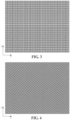
- the panel surface data acquisition and surface definition development system 10 depicted in Figures 1 and 2 also includes two or more displays 14 - 24. Each display projects a contrasting pattern, such as, for example, those patterns shown in Figures 4 and 5 , which pattern is projected onto the surface of the panel as it is conveyed beneath the screens.
- the system 10 also includes two or more cameras 28 - 40. Each one of the cameras 28 - 40 is uniquely paired with one of each of the corresponding number of displays 14 - 26. In the depicted embodiment of the system 10, an aperture is formed in the center of each of the displays 14 - 26.
- each camera may be alternatively arranged at other locations with respect to its associated display, so long as the camera is positioned to detect the reflected image of the pattern projected on the surface of the panel from that display, and not detect reflected images of patterns projected from other displays in its field of view.
- the number and placement of the displays is dependent upon the size of the displays, as well as the width and the curvature of the panel.
- the camera/display pairs are positioned such that the principal viewing axis of each camera is generally perpendicular to the surface of the panel.
- the total number of camera/display pairs must be sufficient such that the total number of projected patterns span the entire width of the surface of the panel part to be analyzed.
- the panel surface data acquisition and surface definition development system 10 also includes a programmable control, depicted in this embodiment as a computer 42, which includes at least one processor programmed to detect the panel as it advances on the conveyor, control each of the cameras 28 - 40 to acquire one or more images of the pattern reflected off the surface of the panel as it is conveyed below the cameras/displays, and construct the definition of the panel surface (using, for example, the technique depicted and described in Figures 7-9 , and as further described hereinafter).
- a programmable control depicted in this embodiment as a computer 42, which includes at least one processor programmed to detect the panel as it advances on the conveyor, control each of the cameras 28 - 40 to acquire one or more images of the pattern reflected off the surface of the panel as it is conveyed below the cameras/displays, and construct the definition of the panel surface (using, for example, the technique depicted and described in Figures 7-9 , and as further described hereinafter).
- the system control may be programmed to acquire multiple images as the glass is conveyed in the first direction. It will be appreciated that the number of images acquire by each camera should be sufficient that the surface information developed from each image (as hereinafter described) can be combined to form a description of the entire surface across the height (i.e., in the direction of conveyance) of the panel.
- the system control 42 may be programmed to acquire multiple images as the glass is conveyed in the first direction to insure that an image of the reflected pattern is obtained in a previous or subsequent image of the moving sheet for that portion of the surface of the panel that, in any one of the captured images, is in the area of reflection of the display aperture.
- the number of images acquire by each camera should also be sufficient that the surface information developed from each image (as hereinafter described) can be combined to form a description of the entire surface across the height in the area in which a single image might include an image of the display aperture rather than the reflected pattern.
- the surface descriptions for each of the cameras are similarly combined to form a description of the entire surface across the width (or across the area of interest in the direction of the width) of the panel.
- the screen pattern is a three-frequency pattern constructed by superimposition of three different frequency sinusoidal patterns in each of the x and y directions of the coordinate system employed by the system logic.
- the x - y coordinate system axes are chosen to be oriented such that they are coincident with the x and y axes of the display (and, as well, the y axis is parallel to the direction of travel of the conveyor and the x axis is orthogonal to the direction of travel of the conveyor).
- the sinusoidal patterns are chosen and combined to insure that the portion of the resultant pattern appearing on the display is non-repetitive, thereby ensuring that, for the image data collected, each pixel in the camera's field of view will correspond uniquely to a single point on the display.
- Each of the three frequencies may be relatively prime values, and are selected such that they are spaced apart within the envelope of frequencies bound by the minimum and maximum frequency limits of the camera's optics.
- the image of this three-frequency pattern reflected from the surface of the panel may then be mathematically deconstructed into three single frequency images in each of the x and y direction. Phase information corresponding to each of the three frequencies can then be isolated and utilized as hereinafter described to develop an accurate three-dimensional description of the panel surface.
- a two-frequency pattern may be utilized.
- This two-frequency pattern may be constructed by superimposition of two different frequency sinusoidal patterns in each of two orthogonal directions which are rotated (or skewed) about the axes that are used to separate the analysis into orthogonal components, such that each of the sinusoidal components of the pattern yields phase information in both the x and y directions.
- the x, y coordinate system axes that are used by the system logic to separate the analysis into orthogonal components are coincident with the x and y axes of the display (and the y axis is as well, coincident with the direction of conveyance).
- the orthogonal directions of the sinusoidal patterns are skewed from the x and y axes of the display. It will be appreciated, however, that any other convenient orientation may be chosen for the axes that are used by the system to separate the analysis into orthogonal components, so long as the sinusoidal patterns are rotated about the axes that are used to separate the analysis into orthogonal components to yield phase information in both the x and y directions.
- the sinusoidal patterns are chosen (relatively prime frequencies and spaced apart as described above) and combined to insure that the portion of the resultant pattern appearing on the display is non-repetitive, thereby ensuring that the image data collected that each pixel in the camera's field of view will correspond uniquely to a single point on the display.
- phase information corresponding to each of the two frequencies can be isolated and utilized as hereinafter described to develop an accurate three-dimensional description of the panel surface.
- an accurate mathematical description of the panel surface may be obtained from a single image for each point on the surface of the panel from which the camera detects the reflected pattern.
- first zone display 20 is oriented at an angle of about 25° counterclockwise from horizontal (when viewed as in Figure 1 ), display 18 is angled at about 15° counterclockwise, display 16 is angled at about 7.5° counterclockwise, display 14 is approximately horizontal, display 22 is angled at approximately 7.5° clockwise from horizontal, display 24 is angled at about 15° clockwise, and display 26 is angled at about 25° clockwise.
- the seven displays 14 - 26 are arranged in the direction of conveyance of the panel.
- the screens are arranged such that each associated camera detects only the reflected pattern from its associated display in its field of view, and the surface areas detected by all cameras together comprise the surface across the entire width of the panel part.
- the panel surface data acquisition and surface definition development system 10 includes a surface data acquisition system which employs the above-described camera and display pairs and acquired images, as well as logic for developing an accurate three-dimensional description of the surface from the reflected patterns from each image, and logic for combining the surface descriptions developed from the images as hereinafter described to obtain an accurate mathematical description of the entire surface of the panel.
- the system 10 may also, in addition to the surface data acquisition system, include one or more computers and/or programmable controls including logic for processing the acquired surface data to analyze the optical characteristics of the panel.
- one or more additional images may be obtained from each camera, as required, as the panel moves on the conveyor.
- the number of images acquired by each camera is determined by at least two considerations. First, in embodiments of the system wherein the cameras are mounted within an aperture of their associated displays, a sufficient number of images must be acquired to ensure that the system acquires a reflected image of the pattern for all of the points in the viewing area, including those points from which the display pattern is not reflected in a particular image due to the fact that it is located within the area that includes a reflection of the aperture.
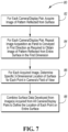
- the system For each of the acquired images, the system, at 86, must determine the precise location in three-space of each point on the surface of the panel based upon the reflected pattern in the image. As previously described, the use of a pattern which is non-repeating in the camera's viewing area ensures that each point on the display screen that is reflected within the viewing area of the camera will be uniquely associated with a pixel that detects the reflected pattern.
- Conventional image processing techniques may be employed to determine the x and y locations (i.e., in the focal plane of the camera) for each point on the surface of the panel that is in the viewing area of the camera for that image. Other known processing techniques may be employed to determine the z location (a.k.a. the elevation) of each point.
- a mapping vector technique is employed (as depicted in figures 8 and 9 , and as more fully described hereinafter) to determine the elevation of each single point on the surface of the glass from the image of the reflected projected pattern.
- one or more other coordinate systems/origins may be selected and employed based upon a particular system's camera/display architecture and/or for computational convenience.
- the combination of the surface developed from the individual acquired images may be performed using other conventional image data processing techniques.
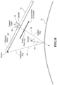
- Figures 8 and 9 illustrate, respectively, the theoretical basis and the method performed by the control logic for determining the elevation (z value) of each point on the surface of the glass from the image of the reflected projected pattern for each acquired image.
- Figure 8 illustrates the pertinent geometrical relationships between the camera 28, the display screen 14, and the surface of the panel (which is depicted in Figure 8 as a glass sheet, G).
- the three principles used to determine the elevation of a single point on the surface of the panel from a reflected projected image are (1) the surface of any object can be defined by the normal vector 92 for each discrete point of the surface; (2) the law of reflection defines the normal vector 92 at each point by bisecting the angle between the incident ray 94 and the reflected ray 96 of light (also referred to herein as the "geometric optical” or “reflection angle” equation); and (3) the normal vector can also be defined by the differential geometry which describes each point on the surface of the panel (also referred to herein as the "differential geometry” equation).
- the incident ray is defined entirely by the camera intrinsics.
- each pixel in the cameras receptor cell at the cameras origin 98 sees a point in space at varying distances through the lens.
- the reflected ray 96 is defined by a screen position and a surface point on the glass. The distance is constrained only where it intersects the incident ray 94.
- mapping vector 100 To solve the corresponding differential equations, a mapping vector 100 needs to be established, which defines, for each pixel, where the reflected ray will hit the projected pattern on the display (viewed from the camera origin). Once the mapping field (i.e., the set of mapping vectors for each pixel in the camera's field of view) is established, the distances from the camera's origin and each discrete point on the surface can be calculated.
- mapping field i.e., the set of mapping vectors for each pixel in the camera's field of view
- n ⁇ v ⁇ m ⁇ ⁇ s v ⁇ v ⁇ ⁇ m ⁇ ⁇ s v ⁇ v ⁇ v ⁇
- n is the surface normal
- v is the camera pixel vector
- m is the mapping vector
- n ⁇ ⁇ p ⁇ ⁇ x ⁇ ⁇ p ⁇ ⁇ y
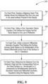
- Figure 9 illustrates how a suitably programmed computer could implement this mapping vector technique 102.
- the system develops a mapping vector that defines where the reflected ray projects to the display (again, viewed mathematically from the camera origin).
- a first expression, the geometric optical equation, at 106 defines the surface normal vector for each point on the panel surface within the camera's viewing area based upon the law of reflection.
- a second equation, the differential geometry equation, at 108 defines the surface normal vector-based on the multiplication of the partial differentials which describe the point on the surface in the x, y directions.
- mapping vector to obtain the elevation, s (that is, the z distance - the distance between the glass surface and the camera origin) for each point on the panel surface that is within the viewing area of the camera.
- This information coupled with the previously developed x and y locations of each surface point, yields a specific description, in x, y, and z , for each point on the surface.
- the disclosed panel surface data acquisition and surface definition development system 10 may be mounted in-line to inspect panels as they are transported on a conveyor associated with a panel processing system which performs multiple fabricating operations on the panels.
- the disclosed system 10 includes a surface data acquisition system and a computer including logic for receiving the captured image data, and developing a three-dimension description of the panel surface from the image data.
- the system 10 may, as well, perform one or more analyses utilizing the developed surface, such as known optical processing, gaging, and/or other surface related analyses as previously described, and display or otherwise report selected information associated with the analyses.
- computer 42 may be operably connected to the conveyor and cameras to perform the image acquisition, the surface development, and the optical processing described herein. Alternatively, computer 42 may be combined with one or more other computers and/or programmable controls to perform these functions.
- the system 10 may also be programmed by the user to graphically and numerically display characteristics of the surface, including, for example, various indicia of optical distortion and/or gaging, and/or other indicia considered relevant in the industry to the analysis of the quality of formed and fabricated panels.
- the digital cameras 28 - 40 are each connected via a conventional data line to one or more computers, such as computer 42, which may be suitably programmed to acquire the digital image data from the camera, process the image data to obtain the desired surface definition for the panel, and analyze the data to develop various indicia of distortion.
- the computer 42 may also be programmed to present the developed information in both graphical (e.g., color-coded images) and statistical forms. If desired, various other statistical data can be derived and reported for predefined areas of the panel.
- the panel surface data acquisition and surface definition development system 10 may additionally or alternatively employ other known image processing techniques to collect and analyze the acquired image data and develop a definition of the surface.
- the displays 14 - 26 are light boxes that utilize conventional lighting (such as fluorescent lights) behind a translucent panel upon which the contrasting pattern is printed, painted, or otherwise applied using conventional methods.
- the digital cameras 28 - 40 are connected to the computer 60 using known methods, preferably so that the acquisition of the image by the camera may be controlled by the computer 42.
- FIG 11 illustrates a typical glass sheet heating, bending, and tempering system 200 which includes the in-line surface data acquisition and surface definition development system 10.
- the glass sheets enter a heating zone 202 where the glass is softened to a temperature suitable for forming the glass into the desired shape.
- the heated glass sheet is then conveyed to a bending station 204 where the softened sheet is formed to the desired shape, and thereafter further conveyed to a cooling station 206 where the glass sheet is cooled in a controlled manner to achieve the appropriate physical characteristics.
- the glass sheet would then be conveyed out of the cooling station onto a conveyor from which the sheet is conveyed for image acquisition and analysis by the disclosed system 10.
- the glass sheet would be moved on the conveyor 12 for further processing.
- transport and conveyance of the glass can be achieved by using known techniques such as by roller, air-float, or belt conveyors, positioners, and robotic arms, in order to handle the glass in the manner described.
- a plurality of conveyors each of which may be independently controlled to move the glass sheets through the different processing stations at speeds to efficiently govern the flow and processing of the glass sheets throughout the system 200.
- Figure 12 similarly schematically illustrates an in-line surface data acquisition and surface definition development system 10 in a typical automotive windshield fabrication system 300, which may include a heating station 302, a bending station 304, a cooling station 306, and a lamination station 308, upstream of the optical inspection system 10.
- Selected data output by the system 10 may also be provided as input to the control logic for the associated glass sheet heating, bending, and tempering system 200 (or automotive windshield fabrication system 300) to allow the control(s) associated with one or more of the stations the glass sheet system to modify its (their) operating parameters as a function of the optical data developed from previously processed glass sheets.
- the surface data acquisition and surface definition development system 10 of the present invention could alternatively be mounted in-line at various other points in the above-described and other panel fabrication systems as desired to maximize the production rate of the system, so long as the optical distortion measurements are taken after the panel has been formed to its final shape.
Landscapes
- Engineering & Computer Science (AREA)
- Physics & Mathematics (AREA)
- General Physics & Mathematics (AREA)
- Computer Vision & Pattern Recognition (AREA)
- Chemical & Material Sciences (AREA)
- Optics & Photonics (AREA)
- Theoretical Computer Science (AREA)
- Health & Medical Sciences (AREA)
- Life Sciences & Earth Sciences (AREA)
- Textile Engineering (AREA)
- Analytical Chemistry (AREA)
- Biochemistry (AREA)
- General Health & Medical Sciences (AREA)
- Immunology (AREA)
- Pathology (AREA)
- Signal Processing (AREA)
- Multimedia (AREA)
- Length Measuring Devices By Optical Means (AREA)
- Materials Engineering (AREA)
- Organic Chemistry (AREA)
- Image Processing (AREA)
Claims (14)
- System (10) zum Erfassen von Oberflächendaten von einer der Oberflächen einer im Wesentlichen rechteckigen, gekrümmten Platte (G) mit einer spiegelnden Oberfläche von Interesse mit einer ersten Abmessung und einer zweiten Abmessung, wobei die Platte (G) zumindest um eine oder mehrere Krümmungsachsen gekrümmt ist, die im Wesentlichen parallel zur ersten Abmessung sind, und zum Entwickeln einer Oberflächendefinition der Platte (G), wobei das System (10) umfasst:eine Fördereinrichtung (12) zum Fördern der Platte (G) in einer zur ersten Abmessung der Platte (G) im Wesentlichen parallelen ersten Richtung;mindestens zwei Anzeigevorrichtungen (14-26), wobei jede Anzeigevorrichtung ein vorgewähltes Kontrastmuster projiziert,mindestens zwei Kameras (28-40; 82); undeine programmierbare Steuerung mit mindestens einem Prozessor, der programmiert ist zum Ausführen einer Logik zum Steuern jeder der Kameras (28-40; 82), um mindestens ein Bild des reflektierten Musters der zugeordneten Anzeigevorrichtung auf der Platte (G) zu erfassen, während die Platte (G) in der ersten Richtung über den Weg des projizierten Musters transportiert wird, und einer Logik zum Analysieren und Kombinieren der von den Kameras (28-40; 82) aufgenommenen Daten, um Oberflächendaten zu erstellen, die eine dreidimensionale Form der Oberfläche der Platte (G) darstellen;dadurch gekennzeichnet, dass jede der mindestens zwei Kameras (28-40; 82) eindeutig mit einer der Anzeigevorrichtungen (14-26) verpaart ist, wobei jedes Paar von Anzeigevorrichtung und Kamera voneinander beabstandet in einem bekannten Abstand und Winkel von der Oberfläche der Platte (G) so angebracht ist, dass die Kamera das reflektierte Bild des von ihrer zugeordneten Anzeigevorrichtung auf die Oberfläche der Platte (G) projizierten Musters erfasst, und wobei jedes der Paare von Anzeigevorrichtung und Kamera zumindest in einer zweiten Richtung quer zur zweiten Abmessung der Platte (G) voneinander beabstandet sind, so dass jede Kamera nur das von ihrer zugeordneten Anzeigevorrichtung auf die Oberfläche der Platte (G) projizierte reflektierte Bild des Musters erfasst, und wobei die von der Mehrzahl von Kameras (28-40; 82) erfassten Muster zusammen die gesamte Oberfläche in der Richtung der zweiten Abmessung der Platte (G) abdecken.
- System (10) nach Anspruch 1, dadurch gekennzeichnet, dass die erste Abmessung die kürzere Abmessung der Platte (G) ist und die zweite Abmessung die längere Abmessung der Platte (G) ist.
- System (10) nach Anspruch 1, dadurch gekennzeichnet, dass die Logik zum Analysieren und Kombinieren der von den Kameras (28-40; 82) aufgenommenen Daten, um Oberflächendaten zu erstellen, die die Oberfläche der Platte (G) darstellen, eine Logik zum Erstellen von Oberflächendaten umfasst, die für die gesamte Oberfläche über die zweite Dimension der Platte (G) hinweg repräsentativ sind.
- System (10) nach Anspruch 1, dadurch gekennzeichnet, dass ein einzelnes Bild der von den Anzeigevorrichtungen (14-26) projizierten reflektierten Muster von jeder der zugeordneten Kameras (28-40; 82) nicht kombiniert werden kann, um Daten zu definieren, die für die Oberfläche der Platte (G) über die gesamte zweite Abmessung der Platte (G) hinweg repräsentativ sind, und bei dem die programmierbare Steuerung mindestens einen Prozessor, der programmiert ist, um eine Logik zum Steuern jeder der Kameras (28-40; 82) auszuführen, um mehrere Bilder des reflektierten Musters der zugeordneten Anzeige auf der Platte (G) zu erfassen, während die Platte (G) in der ersten Richtung über den Weg des projizierten Musters transportiert wird, und eine Logik zum Analysieren und Kombinieren der durch die von jeder Kamera erfassten mehreren Bilder erfassten Daten umfasst, um Oberflächendaten zu erstellen, die für die Oberfläche der Platte (G) über die gesamte erste Abmessung der Platte (G) hinweg repräsentativ sind.
- System (10) nach Anspruch 1, dadurch gekennzeichnet, dass jede Anzeigevorrichtung eine Blende umfasst und bei dem die zugeordnete Kamera hinter ihrer zugeordneten Anzeigevorrichtung so angebracht ist, dass die Hauptachse der Kamera im Wesentlichen senkrecht zur Oberfläche der Anzeigevorrichtung steht und das Bild von der Kamera durch die Blende empfangen wird, und bei dem die programmierbare Steuerung eine Logik zum Steuern jeder der Kameras (28-40; 82), um mehrere Bilder des reflektierten Musters der zugeordneten Anzeigevorrichtung auf der Platte (G) zu erfassen, während die Platte (G) in der ersten Richtung über mindestens eine Strecke transportiert wird, die größer ist als die Größe der Blende, und eine Logik zum Analysieren und Kombinieren der Daten aus den mehreren Bildern, um Daten zu definieren, die die Oberfläche der Platte (G) in dem Bereich repräsentieren, für den eines der aufgenommenen Bilder ein reflektiertes Bild der Blende enthält, umfasst.
- System (10) nach Anspruch 1, dadurch gekennzeichnet, dass die Logik zum Analysieren und Kombinieren der von den Kameras (28-40; 82) erfassten Daten zum Erstellen von Oberflächendaten, die die Oberfläche der Platte (G) repräsentieren, mindestens umfasst:eine Logik zum Entwickeln eines Abbildungsvektors für jedes Pixel im Blickbereich der Kamera für jedes erfasste Bild, der definiert, wo der reflektierte Strahl vom Kameraursprung zur zugeordneten Anzeige verläuft; undeine Logik zum Ermitteln des Höhenwerts s des Punkts für jedes Pixel im Blickbereich der Kamera für jedes erfasste Bild durch gleichzeitiges Lösen (1) einer geometrisch-optischen Gleichung und (2) einer geometrischen Differentialgleichung unter Verwendung des Abbildungsvektors.
- System (10) nach Anspruch 1, dadurch gekennzeichnet, dass das vorgewählte Kontrastmuster sich über den gesamten Blickbereich der Kamera nicht wiederholt.
- System (10) nach Anspruch 7, dadurch gekennzeichnet, dass das vorgewählte Kontrastmuster ein Dreifrequenzmuster ist, das durch Überlagerung von drei sinusförmigen Mustern mit unterschiedlichen Frequenzen in x- und in y-Richtung des von der Logik des Systems (10) verwendeten Koordinatensystems konstruiert ist.
- System (10) nach Anspruch 7, dadurch gekennzeichnet, dass das vorgewählte Kontrastmuster ein Zweifrequenzmuster ist, das durch Überlagerung von zwei sinusförmigen Mustern mit unterschiedlichen Frequenzen in x- und in y-Richtung des Musters gebildet wird, wobei die beiden sinusförmigen Muster mit unterschiedlichen Frequenzen in Bezug auf die Achsen des von der Logik des Systems (10) verwendeten Koordinatensystems gedreht sind.
- System (10) nach Anspruch 1, dadurch gekennzeichnet, dass die programmierbare Steuerung programmiert ist, um eine Logik zum Analysieren der für die dreidimensionale Form der Oberfläche der Platte (G) repräsentativen Oberflächendaten auszuführen, um Anzeichen einer mit ausgewählten Punkten von Interesse auf der Platte (G) assoziierten reflektierten optischen Verzerrung zu entwickeln.
- System (10) nach Anspruch 1, dadurch gekennzeichnet, dass die programmierbare Steuerung programmiert ist, um eine Logik zum Vergleichen einer entwickelten Oberfläche an ausgewählten Punkten von Interesse mit einer vordefinierten beispielhaften Oberfläche auszuführen, um die Übereinstimmung der Platte (G) mit der dreidimensionalen Form der vordefinierten beispielhaften Oberfläche zu beurteilen.
- Verfahren zum Erfassen von Oberflächendaten von einer der Oberflächen einer im Wesentlichen rechteckigen, gekrümmten Platte (G) mit einer Oberfläche von Interesse mit einer ersten Abmessung und einer zweiten Abmessung, wobei die Platte (G) zumindest um eine oder mehrere Krümmungsachsen gekrümmt ist, die im Wesentlichen parallel zur ersten Abmessung sind, und zum Entwickeln einer Oberflächendefinition der Platte (G), dadurch gekennzeichnet, dass das Verfahren zumindest die folgenden Schritte umfasst:Fördern der Platte (G) in einer ersten Richtung, die im Wesentlichen parallel zur ersten Abmessung der Platte (G) verläuft;Projizieren eines vorgewählten Kontrastmusters von mindestens einer Anzeigevorrichtung (14-26) auf die Oberfläche der Platte (G);Bereitstellen mindestens einer Kamera, die mit mindestens einer der mindestens einen Anzeigevorrichtungen (14-26) verpaart ist, wobei die Anzeigevorrichtung und die Kamera beabstandet voneinander in einem bekannten Abstand und Winkel von der Oberfläche der Platte (G) angebracht sind, um das von der Anzeigevorrichtung auf die Oberfläche der Platte (G) projizierte Muster zu erfassen, und wobei das von der Kamera erfasste Muster den gesamten Bereich von Interesse auf der Oberfläche in Richtung der zweiten Abmessung der Platte (G) abdeckt;Steuern der Kamera, um mindestens ein Bild des reflektierten Musters auf der Platte (G) zu erfassen, während die Platte (G) in der ersten Richtung durch den Weg des projizierten Musters transportiert wird; undAnalysieren und Kombinieren der von der Kamera erfassten Daten, um Oberflächendaten zu erstellen, die die dreidimensionale Form der Oberfläche der Platte (G) darstellen, einschließlich mindestens der folgenden Schritte:Entwickeln eines Abbildungsvektors für jedes Pixel im Sichtbereich der Kamera und für jedes erfasste Bild, der definiert, wo der reflektierte Strahl vom Ursprung der Kamera zu der zugeordneten Anzeigevorrichtung verläuft, undEntwickeln des Höhenwerts s des Punkts für jedes Pixel im Sichtbereich der Kamera für jedes erfasste Bild durch gleichzeitiges Lösen (1) einer geometrisch-optischen Gleichung und (2) einer geometrischen Differentialgleichung unter Verwendung des Abbildungsvektors; undwobei mindestens zwei Anzeigevorrichtungen (14-26) vorgesehen sind und die gleiche Anzahl von Kameras (28-40; 82) vorgesehen ist, und jede der Kameras (28-40; 82) eindeutig mit einer der Anzeigevorrichtungen (14-26) verpaart ist, wobei jede Anzeigevorrichtung und jede eindeutig verpaarte Kamera voneinander beabstandet in einem bekannten Abstand und Winkel von der Oberfläche der Platte (G) angebracht sind, um das reflektierte Bild des Musters zu erfassen, das von der zugeordneten Anzeigevorrichtung auf die Oberfläche der Platte (G) projiziert wird, und wobei jedes der Paare aus Anzeigevorrichtung und Kamera zumindest in einer zweiten Richtung quer zur zweiten Abmessung der Platte (G) voneinander beabstandet sind, so dass jede Kamera nur das von ihrer zugeordneten Anzeigevorrichtung auf die Oberfläche der Platte (G) projizierte reflektierte Bild des Musters erfasst, und bei dem die von den Kameras (28-40; 82) erfassten Muster zusammen die gesamte Oberfläche in der Richtung der zweiten Abmessung der Platte (G) abdecken.
- Verfahren nach Anspruch 12, dadurch gekennzeichnet, dass die Schritte des Analysierens und Kombinierens der Daten den Schritt des Analysierens der für die dreidimensionale Form der Oberfläche der Platte (G) repräsentativen Oberflächendaten umfassen, um Anzeichen einer Punkten von Interesse auf der Platte (G) zugeordneten optischen Verzerrung zu ermitteln.
- Verfahren nach Anspruch 12, dadurch gekennzeichnet, dass die Schritte des Analysierens und Kombinierens der Daten den Schritt des Vergleichens ausgewählter Punkte von Interesse der entwickelten Oberfläche mit einer vordefinierten Beispieloberfläche umfassen, um die Übereinstimmung der Platte (G) mit der dreidimensionalen Form der vordefinierten Beispieloberfläche zu beurteilen.
Applications Claiming Priority (2)
| Application Number | Priority Date | Filing Date | Title |
|---|---|---|---|
| US14/752,061 US9952037B2 (en) | 2015-06-26 | 2015-06-26 | System and method for developing three-dimensional surface information corresponding to a contoured sheet |
| PCT/US2016/032851 WO2016209413A1 (en) | 2015-06-26 | 2016-05-17 | System and method for developing three-dimensional surface information corresponding to a contoured sheet |
Publications (4)
| Publication Number | Publication Date |
|---|---|
| EP3314529A1 EP3314529A1 (de) | 2018-05-02 |
| EP3314529A4 EP3314529A4 (de) | 2018-12-05 |
| EP3314529B1 true EP3314529B1 (de) | 2025-07-02 |
| EP3314529C0 EP3314529C0 (de) | 2025-07-02 |
Family
ID=57586421
Family Applications (1)
| Application Number | Title | Priority Date | Filing Date |
|---|---|---|---|
| EP16814893.0A Active EP3314529B1 (de) | 2015-06-26 | 2016-05-17 | System und verfahren zur entwicklung dreidimensionaler oberflächeninformationen entsprechend einem konturierten bogen |
Country Status (6)
| Country | Link |
|---|---|
| US (1) | US9952037B2 (de) |
| EP (1) | EP3314529B1 (de) |
| CN (1) | CN107924454B (de) |
| BR (1) | BR112017028017A2 (de) |
| MX (1) | MX390407B (de) |
| WO (1) | WO2016209413A1 (de) |
Families Citing this family (10)
| Publication number | Priority date | Publication date | Assignee | Title |
|---|---|---|---|---|
| US9952039B2 (en) | 2015-06-26 | 2018-04-24 | Glasstech, Inc. | System and method for measuring reflected optical distortion in contoured panels having specular surfaces |
| US9470641B1 (en) | 2015-06-26 | 2016-10-18 | Glasstech, Inc. | System and method for measuring reflected optical distortion in contoured glass sheets |
| US9841276B2 (en) | 2015-06-26 | 2017-12-12 | Glasstech, Inc. | System and method for developing three-dimensional surface information corresponding to a contoured glass sheet |
| US9851200B2 (en) | 2015-06-26 | 2017-12-26 | Glasstech, Inc. | Non-contact gaging system and method for contoured panels having specular surfaces |
| US9933251B2 (en) | 2015-06-26 | 2018-04-03 | Glasstech, Inc. | Non-contact gaging system and method for contoured glass sheets |
| JP7087458B2 (ja) * | 2018-03-06 | 2022-06-21 | オムロン株式会社 | 画像検査装置、画像検査方法及び画像検査プログラム |
| JP7076280B2 (ja) * | 2018-04-27 | 2022-05-27 | 日立造船株式会社 | 測定方法および測定装置 |
| DE102018121337A1 (de) * | 2018-08-31 | 2020-03-05 | NoKra Optische Prüftechnik und Automation GmbH | Verfahren zur Bestimmung der Krümmung einer Glasscheibe, insbesondere einer Windschutzscheibe |
| FR3101420B1 (fr) * | 2019-09-30 | 2023-12-29 | Saint Gobain | Méthode d’évaluation de la qualité optique d’une zone délimitée d’un vitrage |
| CN112541405B (zh) * | 2020-11-27 | 2024-07-19 | 陕西海泰电子有限责任公司 | 一种非线性双频图的自动识别方法 |
Citations (1)
| Publication number | Priority date | Publication date | Assignee | Title |
|---|---|---|---|---|
| US20100309328A1 (en) * | 2008-02-15 | 2010-12-09 | Pilington Group Limited | Method of determination of glass surface shapes and optical distortion by reflected optical imaging |
Family Cites Families (53)
| Publication number | Priority date | Publication date | Assignee | Title |
|---|---|---|---|---|
| US4585343A (en) | 1983-11-04 | 1986-04-29 | Libbey-Owens-Ford Company | Apparatus and method for inspecting glass |
| US4629319A (en) | 1984-02-14 | 1986-12-16 | Diffracto Ltd. | Panel surface flaw inspection |
| US4989984A (en) | 1989-11-08 | 1991-02-05 | Environmental Research Institute Of Michigan | System for measuring optical characteristics of curved surfaces |
| FR2688310A1 (fr) * | 1992-03-03 | 1993-09-10 | Saint Gobain Vitrage Int | Procede et dispositif de controle de la transparence d'un vitrage feuillete. |
| US5574274A (en) | 1995-02-21 | 1996-11-12 | Microtek International, Inc. | Transmissive/reflective optical scanning apparatus |
| US5726749A (en) * | 1996-09-20 | 1998-03-10 | Libbey-Owens-Ford Co. | Method and apparatus for inspection and evaluation of angular deviation and distortion defects for transparent sheets |
| DE19643018B4 (de) | 1996-10-18 | 2010-06-17 | Isra Surface Vision Gmbh | Verfahren und Vorrichtung zum Messen des Verlaufs reflektierender Oberflächen |
| US6031221A (en) | 1998-02-19 | 2000-02-29 | Emhart Glass S.A. | Container inspection machine |
| DE19849802A1 (de) * | 1998-10-29 | 2000-05-04 | Volkswagen Ag | Lackfehlererkennung und Beseitigung |
| US6100990A (en) | 1999-06-14 | 2000-08-08 | Ford Motor Company | Method and apparatus for determining reflective optical quality using gray-scale patterns |
| US6512239B1 (en) | 2000-06-27 | 2003-01-28 | Photon Dynamics Canada Inc. | Stereo vision inspection system for transparent media |
| AU2001288641A1 (en) | 2000-09-01 | 2002-03-13 | Mark M. Abbott | Optical system for imaging distortions in moving reflective sheets |
| FR2817042B1 (fr) | 2000-11-22 | 2003-06-20 | Saint Gobain | Procede et dispositif d'analyse de la surface d'un substrat |
| DE10127304C5 (de) | 2001-06-06 | 2007-07-19 | Technische Universität Carolo-Wilhelmina Zu Braunschweig | Verfahren und Vorrichtung zur Bestimmung der dreidimensionalen Kontur einer spiegelnden Oberfläche eines Objektes |
| US7106325B2 (en) | 2001-08-03 | 2006-09-12 | Hewlett-Packard Development Company, L.P. | System and method for rendering digital images having surface reflectance properties |
| US6985231B2 (en) | 2001-09-20 | 2006-01-10 | Strainoptics, Inc. | Method and apparatus for measuring the optical quality of a reflective surface |
| KR101064161B1 (ko) * | 2003-03-07 | 2011-09-15 | 인터내셔널 인더스트리 서포트, 인코포레이티드 | 스테레오 카메라 세트를 갖는 스캐닝 시스템 |
| US8224064B1 (en) | 2003-05-21 | 2012-07-17 | University Of Kentucky Research Foundation, Inc. | System and method for 3D imaging using structured light illumination |
| JP4036268B2 (ja) | 2004-08-06 | 2008-01-23 | 国立大学法人東北大学 | 超低膨張ガラス材料の線膨張係数評価方法 |
| JP4626982B2 (ja) | 2005-02-10 | 2011-02-09 | セントラル硝子株式会社 | ガラス板の端面の欠陥検出装置および検出方法 |
| EP1931973B1 (de) | 2005-09-09 | 2008-12-31 | Sacmi Cooperativa Meccanici Imola Societa' Cooperativa | Verfahren und vorrichtung zur optischen inspektion eines gegenstands |
| JP5156152B2 (ja) | 2005-10-17 | 2013-03-06 | アイ2アイシー コーポレイション | 組み合わせ型の映像ディスプレイおよびカメラシステム |
| DE102005050882B4 (de) | 2005-10-21 | 2008-04-30 | Isra Vision Systems Ag | System und Verfahren zur optischen Inspektion von Glasscheiben |
| US7929751B2 (en) | 2005-11-09 | 2011-04-19 | Gi, Llc | Method and apparatus for absolute-coordinate three-dimensional surface imaging |
| US8358354B2 (en) | 2009-01-26 | 2013-01-22 | The Board Of Trustees Of The Leland Stanford Junior University | Correction of optical abberations |
| DE102006015792A1 (de) | 2006-04-05 | 2007-10-18 | Isra Surface Vision Gmbh | Verfahren und System zur Formmessung einer reflektierenden Oberfläche |
| TWI397995B (zh) | 2006-04-17 | 2013-06-01 | 豪威科技股份有限公司 | 陣列成像系統及其相關方法 |
| JP4174536B2 (ja) | 2006-08-24 | 2008-11-05 | アドバンスド・マスク・インスペクション・テクノロジー株式会社 | 画像補正装置、画像検査装置、及び画像補正方法 |
| WO2008033329A2 (en) * | 2006-09-15 | 2008-03-20 | Sciammarella Cesar A | System and method for analyzing displacements and contouring of surfaces |
| US7471383B2 (en) | 2006-12-19 | 2008-12-30 | Pilkington North America, Inc. | Method of automated quantitative analysis of distortion in shaped vehicle glass by reflected optical imaging |
| CA2675456C (en) | 2007-01-12 | 2017-03-07 | Synergx Technologies Inc. | Bright field and dark field channels, used for automotive glass inspection systems |
| WO2008107892A1 (en) | 2007-03-06 | 2008-09-12 | Advanced Vision Technology (Avt) Ltd. | System and method for detecting the contour of an object on a moving conveyor belt |
| US8126273B2 (en) | 2007-04-05 | 2012-02-28 | Siemens Corporation | Method for reconstructing three-dimensional images from two-dimensional image data |
| DE102007031244B3 (de) | 2007-07-05 | 2009-01-02 | Fraunhofer-Gesellschaft zur Förderung der angewandten Forschung e.V. | Vorrichtung und Verfahren zur Durchführung statischer und dynamischer Streulichtmessungen in kleinen Volumina |
| FR2930030B1 (fr) | 2008-04-11 | 2012-12-28 | Visuol Technologies | Dispositif de controle de la qualite d'une surface |
| US8049879B2 (en) | 2008-04-15 | 2011-11-01 | Glasstech, Inc. | Method and apparatus for measuring transmitted optical distortion in glass sheets |
| FR2936605B1 (fr) * | 2008-10-01 | 2014-10-31 | Saint Gobain | Dispositif d'analyse de la surface d'un substrat |
| US8441532B2 (en) * | 2009-02-24 | 2013-05-14 | Corning Incorporated | Shape measurement of specular reflective surface |
| US8670031B2 (en) | 2009-09-22 | 2014-03-11 | Cyberoptics Corporation | High speed optical inspection system with camera array and compact, integrated illuminator |
| FR2960059B1 (fr) | 2010-05-11 | 2012-12-28 | Visuol Technologies | Installation de controle de la qualite d'une surface d'un objet |
| US8532812B2 (en) | 2010-06-29 | 2013-09-10 | Mitsubishi Electric Research Laboratories, Inc. | System and method for identifying defects of surfaces due to machining processes |
| JP5639797B2 (ja) | 2010-07-01 | 2014-12-10 | 株式会社日立ハイテクノロジーズ | パターンマッチング方法,画像処理装置、及びコンピュータプログラム |
| US20120098959A1 (en) | 2010-10-20 | 2012-04-26 | Glasstech, Inc. | Method and apparatus for measuring transmitted optical distortion in glass sheets |
| FR2975776B1 (fr) | 2011-05-24 | 2014-03-28 | Visuol Technologies | Installation pour le controle de la qualite d'une surface d'un objet |
| WO2013058710A1 (en) | 2011-10-18 | 2013-04-25 | Nanyang Technological University | Apparatus and method for 3d surface measurement |
| CN102788802A (zh) * | 2012-08-29 | 2012-11-21 | 苏州天准精密技术有限公司 | 一种多相机的工件质量检测方法 |
| WO2014145279A1 (en) | 2013-03-15 | 2014-09-18 | Leap Motion, Inc. | Determining the relative locations of multiple motion-tracking devices |
| US9896369B2 (en) | 2014-11-24 | 2018-02-20 | Glasstech, Inc. | Glass sheet forming and annealing providing edge stress control |
| US9470641B1 (en) | 2015-06-26 | 2016-10-18 | Glasstech, Inc. | System and method for measuring reflected optical distortion in contoured glass sheets |
| US9933251B2 (en) | 2015-06-26 | 2018-04-03 | Glasstech, Inc. | Non-contact gaging system and method for contoured glass sheets |
| US9952039B2 (en) | 2015-06-26 | 2018-04-24 | Glasstech, Inc. | System and method for measuring reflected optical distortion in contoured panels having specular surfaces |
| US9841276B2 (en) | 2015-06-26 | 2017-12-12 | Glasstech, Inc. | System and method for developing three-dimensional surface information corresponding to a contoured glass sheet |
| US9851200B2 (en) | 2015-06-26 | 2017-12-26 | Glasstech, Inc. | Non-contact gaging system and method for contoured panels having specular surfaces |
-
2015
- 2015-06-26 US US14/752,061 patent/US9952037B2/en active Active
-
2016
- 2016-05-17 WO PCT/US2016/032851 patent/WO2016209413A1/en not_active Ceased
- 2016-05-17 EP EP16814893.0A patent/EP3314529B1/de active Active
- 2016-05-17 MX MX2018000276A patent/MX390407B/es unknown
- 2016-05-17 CN CN201680037696.2A patent/CN107924454B/zh active Active
- 2016-05-17 BR BR112017028017A patent/BR112017028017A2/pt not_active Application Discontinuation
Patent Citations (1)
| Publication number | Priority date | Publication date | Assignee | Title |
|---|---|---|---|---|
| US20100309328A1 (en) * | 2008-02-15 | 2010-12-09 | Pilington Group Limited | Method of determination of glass surface shapes and optical distortion by reflected optical imaging |
Also Published As
| Publication number | Publication date |
|---|---|
| BR112017028017A2 (pt) | 2018-08-28 |
| MX390407B (es) | 2025-03-20 |
| EP3314529A4 (de) | 2018-12-05 |
| US9952037B2 (en) | 2018-04-24 |
| MX2018000276A (es) | 2018-09-05 |
| CN107924454B (zh) | 2021-12-31 |
| WO2016209413A1 (en) | 2016-12-29 |
| EP3314529C0 (de) | 2025-07-02 |
| CN107924454A (zh) | 2018-04-17 |
| US20160379379A1 (en) | 2016-12-29 |
| CA2990592A1 (en) | 2016-12-29 |
| EP3314529A1 (de) | 2018-05-02 |
Similar Documents
| Publication | Publication Date | Title |
|---|---|---|
| US9846129B2 (en) | System and method for measuring reflected optical distortion in contoured glass sheets | |
| EP3314529B1 (de) | System und verfahren zur entwicklung dreidimensionaler oberflächeninformationen entsprechend einem konturierten bogen | |
| EP3314237B1 (de) | System und verfahren zur entwicklung dreidimensionaler oberflächeninformationen entsprechend einer konturierten glasscheibe | |
| US9952039B2 (en) | System and method for measuring reflected optical distortion in contoured panels having specular surfaces | |
| US9851200B2 (en) | Non-contact gaging system and method for contoured panels having specular surfaces | |
| US10267750B2 (en) | System and associated method for online detection of small defects on/in a glass sheet | |
| EP3580156B1 (de) | System und zugehöriges verfahren zur online-messung der optischen eigenschaften einer glasscheibe | |
| EP2252856B1 (de) | Verfahren zur bestimmung der glasoberflächenform und optischen verzerrung durch reflektierte optische bildgebung | |
| US9933251B2 (en) | Non-contact gaging system and method for contoured glass sheets | |
| US11933601B2 (en) | Method for measuring geometric deviations between the dished surfaces of a plurality of materials to be assessed and a dished surface of a reference material | |
| CA2990592C (en) | System and method for developing three-dimensional surface information corresponding to a contoured sheet |
Legal Events
| Date | Code | Title | Description |
|---|---|---|---|
| STAA | Information on the status of an ep patent application or granted ep patent |
Free format text: STATUS: THE INTERNATIONAL PUBLICATION HAS BEEN MADE |
|
| PUAI | Public reference made under article 153(3) epc to a published international application that has entered the european phase |
Free format text: ORIGINAL CODE: 0009012 |
|
| STAA | Information on the status of an ep patent application or granted ep patent |
Free format text: STATUS: REQUEST FOR EXAMINATION WAS MADE |
|
| 17P | Request for examination filed |
Effective date: 20171221 |
|
| AK | Designated contracting states |
Kind code of ref document: A1 Designated state(s): AL AT BE BG CH CY CZ DE DK EE ES FI FR GB GR HR HU IE IS IT LI LT LU LV MC MK MT NL NO PL PT RO RS SE SI SK SM TR |
|
| AX | Request for extension of the european patent |
Extension state: BA ME |
|
| RIN1 | Information on inventor provided before grant (corrected) |
Inventor name: ADDINGTON, JASON C. Inventor name: MORAN, BENJAMIN L. Inventor name: VILD, MICHAEL J. |
|
| DAV | Request for validation of the european patent (deleted) | ||
| DAX | Request for extension of the european patent (deleted) | ||
| A4 | Supplementary search report drawn up and despatched |
Effective date: 20181026 |
|
| RIC1 | Information provided on ipc code assigned before grant |
Ipc: G01B 11/25 20060101ALI20181022BHEP Ipc: C03B 27/04 20060101ALI20181022BHEP Ipc: G06K 9/00 20060101AFI20181022BHEP Ipc: G01N 21/88 20060101ALI20181022BHEP Ipc: C03B 23/023 20060101ALI20181022BHEP Ipc: G01N 21/896 20060101ALI20181022BHEP Ipc: G01B 11/24 20060101ALI20181022BHEP Ipc: G06T 7/521 20170101ALI20181022BHEP Ipc: C03B 29/08 20060101ALI20181022BHEP Ipc: C03B 35/14 20060101ALI20181022BHEP Ipc: G01N 21/958 20060101ALI20181022BHEP |
|
| STAA | Information on the status of an ep patent application or granted ep patent |
Free format text: STATUS: EXAMINATION IS IN PROGRESS |
|
| 17Q | First examination report despatched |
Effective date: 20210401 |
|
| REG | Reference to a national code |
Ref country code: DE Ref legal event code: R079 Free format text: PREVIOUS MAIN CLASS: G06K0009000000 Ipc: G01N0021896000 Ref document number: 602016092781 Country of ref document: DE |
|
| GRAP | Despatch of communication of intention to grant a patent |
Free format text: ORIGINAL CODE: EPIDOSNIGR1 |
|
| STAA | Information on the status of an ep patent application or granted ep patent |
Free format text: STATUS: GRANT OF PATENT IS INTENDED |
|
| RIC1 | Information provided on ipc code assigned before grant |
Ipc: C03B 23/023 20060101ALI20250219BHEP Ipc: G01N 21/958 20060101ALI20250219BHEP Ipc: G06T 7/521 20170101ALI20250219BHEP Ipc: C03B 29/08 20060101ALI20250219BHEP Ipc: C03B 27/04 20060101ALI20250219BHEP Ipc: C03B 35/14 20060101ALI20250219BHEP Ipc: G01B 11/25 20060101ALI20250219BHEP Ipc: G01N 21/88 20060101ALI20250219BHEP Ipc: G01N 21/896 20060101AFI20250219BHEP |
|
| RAP3 | Party data changed (applicant data changed or rights of an application transferred) |
Owner name: GLASSTECH, INC. |
|
| INTG | Intention to grant announced |
Effective date: 20250319 |
|
| GRAS | Grant fee paid |
Free format text: ORIGINAL CODE: EPIDOSNIGR3 |
|
| GRAA | (expected) grant |
Free format text: ORIGINAL CODE: 0009210 |
|
| STAA | Information on the status of an ep patent application or granted ep patent |
Free format text: STATUS: THE PATENT HAS BEEN GRANTED |
|
| AK | Designated contracting states |
Kind code of ref document: B1 Designated state(s): AL AT BE BG CH CY CZ DE DK EE ES FI FR GB GR HR HU IE IS IT LI LT LU LV MC MK MT NL NO PL PT RO RS SE SI SK SM TR |
|
| REG | Reference to a national code |
Ref country code: GB Ref legal event code: FG4D |
|
| REG | Reference to a national code |
Ref country code: CH Ref legal event code: EP |
|
| REG | Reference to a national code |
Ref country code: IE Ref legal event code: FG4D |
|
| U01 | Request for unitary effect filed |
Effective date: 20250702 |
|
| U07 | Unitary effect registered |
Designated state(s): AT BE BG DE DK EE FI FR IT LT LU LV MT NL PT RO SE SI Effective date: 20250708 |