EP3314102B1 - Einspritzvorrichtung - Google Patents
Einspritzvorrichtung Download PDFInfo
- Publication number
- EP3314102B1 EP3314102B1 EP16719378.8A EP16719378A EP3314102B1 EP 3314102 B1 EP3314102 B1 EP 3314102B1 EP 16719378 A EP16719378 A EP 16719378A EP 3314102 B1 EP3314102 B1 EP 3314102B1
- Authority
- EP
- European Patent Office
- Prior art keywords
- housing element
- injection device
- region
- axial bore
- piston
- Prior art date
- Legal status (The legal status is an assumption and is not a legal conclusion. Google has not performed a legal analysis and makes no representation as to the accuracy of the status listed.)
- Active
Links
Images


Classifications
-
- F—MECHANICAL ENGINEERING; LIGHTING; HEATING; WEAPONS; BLASTING
- F01—MACHINES OR ENGINES IN GENERAL; ENGINE PLANTS IN GENERAL; STEAM ENGINES
- F01N—GAS-FLOW SILENCERS OR EXHAUST APPARATUS FOR MACHINES OR ENGINES IN GENERAL; GAS-FLOW SILENCERS OR EXHAUST APPARATUS FOR INTERNAL-COMBUSTION ENGINES
- F01N3/00—Exhaust or silencing apparatus having means for purifying, rendering innocuous, or otherwise treating exhaust
- F01N3/08—Exhaust or silencing apparatus having means for purifying, rendering innocuous, or otherwise treating exhaust for rendering innocuous
- F01N3/10—Exhaust or silencing apparatus having means for purifying, rendering innocuous, or otherwise treating exhaust for rendering innocuous by thermal or catalytic conversion of noxious components of exhaust
- F01N3/18—Exhaust or silencing apparatus having means for purifying, rendering innocuous, or otherwise treating exhaust for rendering innocuous by thermal or catalytic conversion of noxious components of exhaust characterised by methods of operation; Control
- F01N3/20—Exhaust or silencing apparatus having means for purifying, rendering innocuous, or otherwise treating exhaust for rendering innocuous by thermal or catalytic conversion of noxious components of exhaust characterised by methods of operation; Control specially adapted for catalytic conversion
- F01N3/206—Adding periodically or continuously substances to exhaust gases for promoting purification, e.g. catalytic material in liquid form, NOx reducing agents
- F01N3/2066—Selective catalytic reduction [SCR]
-
- F—MECHANICAL ENGINEERING; LIGHTING; HEATING; WEAPONS; BLASTING
- F02—COMBUSTION ENGINES; HOT-GAS OR COMBUSTION-PRODUCT ENGINE PLANTS
- F02M—SUPPLYING COMBUSTION ENGINES IN GENERAL WITH COMBUSTIBLE MIXTURES OR CONSTITUENTS THEREOF
- F02M57/00—Fuel-injectors combined or associated with other devices
- F02M57/02—Injectors structurally combined with fuel-injection pumps
- F02M57/022—Injectors structurally combined with fuel-injection pumps characterised by the pump drive
- F02M57/027—Injectors structurally combined with fuel-injection pumps characterised by the pump drive electric
-
- F—MECHANICAL ENGINEERING; LIGHTING; HEATING; WEAPONS; BLASTING
- F02—COMBUSTION ENGINES; HOT-GAS OR COMBUSTION-PRODUCT ENGINE PLANTS
- F02M—SUPPLYING COMBUSTION ENGINES IN GENERAL WITH COMBUSTIBLE MIXTURES OR CONSTITUENTS THEREOF
- F02M63/00—Other fuel-injection apparatus having pertinent characteristics not provided for in groups F02M39/00 - F02M57/00 or F02M67/00; Details, component parts, or accessories of fuel-injection apparatus, not provided for in, or of interest apart from, the apparatus of groups F02M39/00 - F02M61/00 or F02M67/00; Combination of fuel pump with other devices, e.g. lubricating oil pump
- F02M63/0012—Valves
- F02M63/007—Details not provided for in, or of interest apart from, the apparatus of the groups F02M63/0014 - F02M63/0059
- F02M63/0075—Stop members in valves, e.g. plates or disks limiting the movement of armature, valve or spring
-
- F—MECHANICAL ENGINEERING; LIGHTING; HEATING; WEAPONS; BLASTING
- F01—MACHINES OR ENGINES IN GENERAL; ENGINE PLANTS IN GENERAL; STEAM ENGINES
- F01N—GAS-FLOW SILENCERS OR EXHAUST APPARATUS FOR MACHINES OR ENGINES IN GENERAL; GAS-FLOW SILENCERS OR EXHAUST APPARATUS FOR INTERNAL-COMBUSTION ENGINES
- F01N2610/00—Adding substances to exhaust gases
- F01N2610/02—Adding substances to exhaust gases the substance being ammonia or urea
-
- F—MECHANICAL ENGINEERING; LIGHTING; HEATING; WEAPONS; BLASTING
- F01—MACHINES OR ENGINES IN GENERAL; ENGINE PLANTS IN GENERAL; STEAM ENGINES
- F01N—GAS-FLOW SILENCERS OR EXHAUST APPARATUS FOR MACHINES OR ENGINES IN GENERAL; GAS-FLOW SILENCERS OR EXHAUST APPARATUS FOR INTERNAL-COMBUSTION ENGINES
- F01N2610/00—Adding substances to exhaust gases
- F01N2610/11—Adding substances to exhaust gases the substance or part of the dosing system being cooled
-
- F—MECHANICAL ENGINEERING; LIGHTING; HEATING; WEAPONS; BLASTING
- F01—MACHINES OR ENGINES IN GENERAL; ENGINE PLANTS IN GENERAL; STEAM ENGINES
- F01N—GAS-FLOW SILENCERS OR EXHAUST APPARATUS FOR MACHINES OR ENGINES IN GENERAL; GAS-FLOW SILENCERS OR EXHAUST APPARATUS FOR INTERNAL-COMBUSTION ENGINES
- F01N2610/00—Adding substances to exhaust gases
- F01N2610/14—Arrangements for the supply of substances, e.g. conduits
- F01N2610/1433—Pumps
-
- F—MECHANICAL ENGINEERING; LIGHTING; HEATING; WEAPONS; BLASTING
- F01—MACHINES OR ENGINES IN GENERAL; ENGINE PLANTS IN GENERAL; STEAM ENGINES
- F01N—GAS-FLOW SILENCERS OR EXHAUST APPARATUS FOR MACHINES OR ENGINES IN GENERAL; GAS-FLOW SILENCERS OR EXHAUST APPARATUS FOR INTERNAL-COMBUSTION ENGINES
- F01N2610/00—Adding substances to exhaust gases
- F01N2610/14—Arrangements for the supply of substances, e.g. conduits
- F01N2610/1453—Sprayers or atomisers; Arrangement thereof in the exhaust apparatus
-
- F—MECHANICAL ENGINEERING; LIGHTING; HEATING; WEAPONS; BLASTING
- F02—COMBUSTION ENGINES; HOT-GAS OR COMBUSTION-PRODUCT ENGINE PLANTS
- F02M—SUPPLYING COMBUSTION ENGINES IN GENERAL WITH COMBUSTIBLE MIXTURES OR CONSTITUENTS THEREOF
- F02M2200/00—Details of fuel-injection apparatus, not otherwise provided for
- F02M2200/90—Selection of particular materials
- F02M2200/9053—Metals
- F02M2200/9069—Non-magnetic metals
-
- Y—GENERAL TAGGING OF NEW TECHNOLOGICAL DEVELOPMENTS; GENERAL TAGGING OF CROSS-SECTIONAL TECHNOLOGIES SPANNING OVER SEVERAL SECTIONS OF THE IPC; TECHNICAL SUBJECTS COVERED BY FORMER USPC CROSS-REFERENCE ART COLLECTIONS [XRACs] AND DIGESTS
- Y02—TECHNOLOGIES OR APPLICATIONS FOR MITIGATION OR ADAPTATION AGAINST CLIMATE CHANGE
- Y02T—CLIMATE CHANGE MITIGATION TECHNOLOGIES RELATED TO TRANSPORTATION
- Y02T10/00—Road transport of goods or passengers
- Y02T10/10—Internal combustion engine [ICE] based vehicles
- Y02T10/12—Improving ICE efficiencies
Definitions
- the invention relates to an injection device, in particular an injection and metering device, which is provided for injecting a reducing agent into the exhaust gas line of an internal combustion engine.
- SCR process selective catalytic reduction
- a reduction catalyst in particular an aqueous urea solution
- AdBlue aqueous urea solution
- the reducing agent is removed from a tank and injected from an injection device, which is based on the pump / nozzle principle, upstream of the reduction catalyst in the exhaust gas flow of the internal combustion engine.
- the reducing agent In order to optimize the NO x conversion rate, it is advantageous to inject the reducing agent into the exhaust gas flow with a very fine spray and with a powerful pulse. It is therefore advantageous if the reducing agent is compressed prior to injection to an elevated pressure of, for example, 10 bar.
- Injectors are from the publications DE 10 2012 206481 A1 and EP 2 694 859 A1 known.
- the publication DE 10 2012 206481 A1 shows an injection device with an integral housing element which extends along an axis, wherein in the housing element has an axial bore extending along the axis is formed, and wherein in a first region of the axial bore a piston displaceable along the axis is arranged, and in a discharge valve is arranged in a second region of the axial bore.
- the publication EP 2 694 859 A1 shows an injection device with a housing member extending along an axis, wherein in the housing member has an axial bore extending along the axis is formed, and with an outer sleeve, which encloses the housing member along its circumference, so that between the outer sleeve and the housing element is formed an annular coolant space for receiving a coolant.
- the injection device is inherently positioned directly on the exhaust pipe, which is very hot during operation.
- Aqueous urea solution is very corrosive especially at high temperatures and has a low viscosity, which can lead to rapid wear and failure of the injector in narrow guides.
- An injection device comprises an integral housing element which is in particular substantially rotationally symmetrical about an axis and extends along this axis.
- the housing member In the housing member is formed along the axis extending central axial bore.
- a piston displaceable along the axis is arranged in a first region of the axial bore, and a discharge valve with an injection nozzle is provided in a second region of the axial bore.
- the injection nozzle is designed to inject the reducing agent, which is compressed by the piston to an injection pressure during operation, into the exhaust gas line of an internal combustion engine.
- An outer sleeve encloses the housing element along its circumference, so that between the outer sleeve and the housing element, an annular coolant space is formed for receiving a coolant.
- an inner sleeve is arranged such that a coil space is formed between the inner sleeve and the housing element.
- an electric coil is arranged, so that the piston is movable by energizing the coil along the axial bore.
- the reducing agent is completely separated from the cooling circuit. There are no welds or elastomeric seals between the coolant and the reducing agent. Also, the injection valve with the injection nozzle is disposed within the integral housing and completely separated from the coolant.
- At least one of the inner sleeve and the outer sleeve is fluid-tightly connected to the housing member, such as by welding, to provide a fluid-tight sealed coolant space.
- a vent valve is disposed in a third portion of the axial bore formed between the first portion and the second portion of the axial bore.
- gas especially air, which is located at the beginning of operation in a formed in the axial bore pump chamber, completely out of the Pumping pump room to allow trouble-free operation of the injector with a precisely defined injection quantity.
- a magnet armature is formed on the end of the piston facing away from the outlet valve.
- the armature is attracted by a magnetic field generated by energizing the coil, so that the piston is movable by turning on and off the flow of current through the coil.
- the armature is elastically supported by a spring element on the housing element.
- a stop for the magnet armature is formed at the end remote from the outlet valve of the housing element, in order to create a defined starting position for the magnet armature.
- the stop is formed at least partially with a smaller wall thickness than other portions of the housing member to increase the magnetic flux through the magnet armature.
- the wall thickness of the stop can be reduced in particular by forming a groove on the side of the bottom facing away from the magnet armature.
- the groove e.g. by build-up welding, filled with an austenitic material.
- the groove is also closed by an austenitic plate, which is welded to the housing element on the side facing away from the reducing agent.
- the end of the housing member facing away from the outlet valve is closed by a lid to enclose and isolate the fluid to be scrubbed in the injector.
- a lid to enclose and isolate the fluid to be scrubbed in the injector.
- at least one opening can be formed in the cover, through which the fluid to be injected can be supplied to the injection device.
- At least one radial bore is provided in the housing member which is in fluid communication with the axial bore and allows the fluid to be injected to be introduced into the pumping space formed in the axial bore.
- the exit valve is fitted into the axial bore to provide a fluid tight connection between the exit valve and the housing member without the need for a weld to be formed.
- FIG. 1 shows a schematic representation of a system for injecting a liquid reducing agent into an exhaust line 52 of an internal combustion engine 51st
- An injection device 50 which is based in particular on the pump / nozzle principle, is mounted between the internal combustion engine 51 and an SCR catalytic converter 53 arranged downstream of the internal combustion engine 51 on the exhaust line 52.
- a fluid reducing agent 58 to be injected is removed from a storage tank 56 and the injection device 50, with a slightly elevated pressure of for example 2 to 3 bar supplied.
- the injection device 50 further increases the pressure of the reducing agent 58, for example to 10 bar, and injects the reducing agent 58 into the exhaust gas line 52 at the increased pressure.
- the injected reducing agent 58 mixes with the exhaust gases 55 flowing through the exhaust line 52 and reacts in a downstream of the injector 50 arranged SCR catalyst 53 with the nitrogen oxides contained in the exhaust gases 55 (NO x ), these to N 2 and H 2 O can be reduced.
- the mixing of the reducing agent 58 with the exhaust gases 55 may by one or more arranged in the exhaust line 52 mixing elements, which in the Fig. 1 not shown are supported.
- FIG. 2 shows a sectional view through an embodiment of an injection device 50 according to the invention.
- an integral housing element 2 which is substantially cylindrical around one in the FIG. 2 horizontally extending axis A is formed.
- the integral housing element 2 is in particular made of a magnetic material which comprises, for example, a hardened, non-rusting, in particular martensitic stainless steel. A formed from such a material housing element 2 has the required wear resistance and can cause a magnetic flux.
- the housing element 2 has a central axial bore 26 running along the axis A.
- a piston 1 is arranged so as to be movable along a very narrow guide 47 provided by the axial bore 26, parallel to the axis A.
- the piston 1 is made of a material comprising, for example, an austenitic stainless steel, and has in particular by a corresponding surface treatment, such as nitrocarburizing, nitriding, Kolster the, and / or a subsequent carbon coating on a very good wear resistance.
- a magnet armature 3 On the pump room 27 opposite, in the FIG. 2 On the right side of the piston 1 is a magnet armature 3, which is fixedly connected to the piston 1 or formed integrally with the piston 1.
- the armature 3 has in a plane which extends at a right angle to the axis A, a larger diameter than the piston 2.
- the armature 3 is supported by a spring element 23 elastically on the housing element 2.
- the housing element 2 has a cup-shaped region 2 a, which has a larger diameter than the housing element 2 in the region of the piston 1.
- the pot-shaped region 2 a surrounds the magnet armature 3 along its circumference such that a parasitic air gap 34 is formed in the radial direction between the outer circumference of the magnet armature 3 and the inner circumference of the cup-shaped region 2 a and the magnet armature 3 is freely movable parallel to the axis A.
- the cup-shaped region 2a comprises a radially outwardly extending bottom 2b, the inner region of which forms a first stop 28 opposite the magnet armature 3. At least a portion of the bottom 2b of the cup-shaped portion 2a is formed with a reduced wall thickness to increase the magnetic flux between the first stopper 28 and the magneto-tank 3. In order to reduce the wall thickness of the bottom 2b, in the bottom 2b of the pot-shaped region 2a, a circular groove 17 running around the axial bore 26 is formed.
- the groove 17 is filled by build-up welding with an austenitic material, as in the lower part of the FIG. 2 shown.
- the groove 17 may be formed by an austenitic plate 44, which on the side facing away from the reducing agent at the points 45 and 46 to the Housing element 2 is welded, sealed and thereby mechanically stabilized, as in the upper part of FIG. 2 is shown.
- the housing element 2 is closed on the other side of the magnet tanker 3 by a lid 11 welded to the cup-shaped region 2 a of the housing 2 at the point 20. Over the lid 11, an outer cover 30 is attached.
- At least one opening 16 is formed, which makes it possible to guide the fluid to be injected into the interior of the housing element 2.
- a second stop 40 is formed, which limits the path of the magnet armature 3 during its movement along the axis A.
- the at least one opening 16 is formed outside the center of the lid 11.
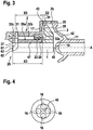
- a plurality of openings 16 may be formed around the second stopper 4, as in the FIG. 4 , which is a cross section through the central region of the lid 11, shown schematically.
- the cover 11 is in particular at least partially elastic, in order to dampen the striking of the magenta tank 3 to the second stop 40. By such a damping both the operating noise and the wear of the injection device 50 can be reduced.
- the cover 11 may also be formed at least partially plastically deformable beyond. In a plastically formed lid 11, the position of the second stopper 40 along the axis A is variable by plastically deforming the lid 11 to set a desired maximum armature stroke.
- the weld 20 between the lid 11 and the housing member 2 is formed on the cold side in the immediate vicinity of the cooling. This reduces the risk of corrosion. Also a rust through at this point would be less critical because the leakage occurring due to the rusting would not get into the cooling circuit.
- axial and radial bores 32a, 32b, 32c are formed, which form a fluid supply into the pump chamber 27 and allow the fluid to be injected from the space 42, the lid 11, the cup-shaped portion 2a and the armature 3 is limited to lead into the pump chamber 27.
- the radial bore 32c is formed from the axial bore 26 to the outer periphery of the housing 2 and there closed fludidicht by a fitted into the radial bore 32c ball 31.
- An outlet valve 57 formed with a nozzle closes the axial bore 26 in a second region 26b on the in the FIG. 2 left side of the housing element 2 from.
- the outlet valve 57 is an outwardly opening valve 57 having a valve piston 6 and a valve and nozzle body 7, which comprises a valve seat 41.
- the valve and nozzle body 7 of the outlet valve 57 is pressed into the housing element 2.
- Such a press fit 33 prevents the corrosive reducing agent from reaching the weld 37, which connects the valve and nozzle body 7 firmly to the housing element 2.
- a vent valve 4 On the side facing away from the piston 1 (in the Fig. 2 left) of the pump chamber 27 is in a third region 26c of the axial bore 26, which is located between the first region 26a and the second region 26b, a vent valve 4 is provided.
- the vent valve 4 makes it possible to pump gas, in particular air, which is located at the start of operation in the pump chamber 27, from the pump chamber 27. Without such a vent valve 4, the volume between the pump chamber side end face of the piston 1 and the downstream outlet valve 7 would be so large that gas, which is in this volume, by moving the piston 1 only compressed, but not completely through the outlet valve 7 the pump room 27 could be promoted out.
- a quantity of gas remaining in the pump chamber 27 would lead to fluctuations in the amount of reducing agent delivered in each pump stroke and prevent a well-defined amount of reducing agent from being constantly injected into the exhaust gas line 52.
- the opening pressure of the vent valve 4 is adjustable via the bias of a vent valve spring 24, for example by a Federab rangelement 5, on which the vent valve spring 24 is supported, is moved in its press fit in the second region 26b of the bore 26 parallel to the axis A.
- the housing element 2 is surrounded along its circumference by an electric coil 8, which can be supplied with electrical current via electrical leads 12.
- an electric coil 8 By energizing the electric coil 8, a magnetic field is generated, which pulls the armature 3 against the elastic force of the spring element 23 in the direction of the first stop 28.
- the piston 1 connected to the armature 3 or integrally formed is also moved in the same direction along the axis A so as to reduce the volume of the pump space 27.
- the pressure in the pump chamber 27 is increased until the opening pressure of the vent valve 4 is reached, so that the vent valve 4 opens and the contents of the pump chamber 27 flows to the outlet valve 57.
- the exhaust valve 57 After further increasing the pressure caused by further movement of the gas tank 3 and the piston 1, the exhaust valve 57 also opens against the force of the exhaust valve spring 25 and the fluid is injected into the exhaust line 52 at high pressure.
- the magneto-tanker 3 and the piston 1 connected to the magneto-tanker 3 are urged back into the starting position by the spring element 23 in the direction of the second stop 40 formed on the cover 11.
- an inner sleeve 9 is formed.
- the inner sleeve 9 is welded at the points 19 and 22 to the housing element 2 and thus forms a fluid-tight closed space which extends around the circumference of the housing 2 and in which the electrical coil 8 is arranged.
- a second, outer sleeve 10 is arranged such that between the outer sleeve 10 and the inner sleeve 9 and between the outer sleeve 10 and the housing member 2, a radial coolant space 39 is formed .
- the outer sleeve 10 is welded at the points 21a and 21b to an outer end face of the valve and nozzle body 7 or to the outer circumference of the cup-shaped area 2a of the housing 2, so that the coolant space 39 is sealed fluid-tight.
- the coolant space 39 is formed with at least one coolant inflow 14 and with at least one coolant outflow 15, which make it possible Coolant, in particular cooling water to lead through the coolant chamber 39 to dissipate the heat transferred from the hot exhaust line 52 in operation and to cool the injector 50.
- the outer sleeve 10 On the hot exhaust line 52 facing in the FIG. 2 On the left side, the outer sleeve 10 is surrounded by an additional heat protection sleeve 13, which faces the exhaust line 52 during operation (in the FIG. 2 left) of the injector 50 creates a heat insulating space 38 to shield the heat emitted by the hot exhaust line 52 during operation.
- the heat protection sleeve 13 is welded at the point 18 annularly with the outer sleeve 10.
- FIG. 3 shows an enlarged partial sectional view of the central portion of the injector 50 with the movable piston 6 in the axial bore 26, the pump chamber 27 and the armature third
- the promotion of the fluid begins as soon as the piston 1, which moves due to the magnetic force generated by energizing the coil 8 to the left, with its the pump chamber 27 facing edge 63, the edge 61 of the bore 32c passes.
- the anchor plate 3 can be reproducibly applied to the piston 1 with very little tolerance, in particular shrunk.
- the size X3 can be manufactured with a very low tolerance.
- the dimension X5 can also be made very precisely.
- One possibility is to first set the transverse bore 32c and then the bottom 2b of the cup-shaped region 2a to the corresponding axial dimension X5.
- the required grinding dimension can be determined by putting the pump chamber 27 under (air) pressure and subsequently closing the radial bore 32c with a so-called master piston.
- the distance X5 between the surface 43 of the edge 61 can then be determined via the pressure drop at the radial bore 32c. According to the result, the surface 43 is reworked to the desired level, for example by grinding.
- the housing element 2 is an integral component, the desired right-angled orientation of the surface 43 to the guide 47 can be optimally realized. This and the integral construction of the housing 2 have the consequence that also the radial parasitic air gap 43 can be produced very accurately.
- the first stop 28 of the magnet armature 3 occupies only a very small area of the bottom 2b on the housing element 2. Since this area is very small, the force of the spring element 23 is sufficient to push the piston 1 to the right against the residual remnant that builds up in the first stop 28. An additional non-magnetic disk between the housing element 2 and the magnet tanker 3 can therefore be dispensed with. By dispensing with such a disc, the axial geometric tolerances can be further minimized.
- the width X2 of the working air gap 43 with closed magnetic circuit results directly from the production. Since the complete anchor side can be machined in one clamping, the geometric tolerances (dimensional, geometrical and positional tolerances) of the air gap 43 are minimal.
- the described embodiment of the invention thus provides an injection device 50 in which the reducing agent is reliably separated from the welds and the coolant by an integral housing element 2.
- the integrally formed housing element 2 makes it possible to produce the metering and injection device 50 with small tolerances and thus to precisely set the desired injection quantity.
Landscapes
- Engineering & Computer Science (AREA)
- Chemical & Material Sciences (AREA)
- Combustion & Propulsion (AREA)
- Mechanical Engineering (AREA)
- General Engineering & Computer Science (AREA)
- Chemical Kinetics & Catalysis (AREA)
- Health & Medical Sciences (AREA)
- Toxicology (AREA)
- Fuel-Injection Apparatus (AREA)
- Exhaust Gas After Treatment (AREA)
Description
- Die Erfindung betrifft eine Einspritzvorrichtung, insbesondere eine Einspritz- und Dosiervorrichtung, die zum Einspritzen eines Reduktionsmittels in den Abgasstrang eines Verbrennungsmotors vorgesehen ist.
- Bei Kraftwagen mit Verbrennungsmotoren, insbesondere Dieselmotoren, muss aufgrund der Abgasgesetzgebung unter anderem der Schadstoff NOx reduziert werden. Eine Methode, die dabei zur Anwendung kommt, ist das Verfahren der sogenannten selektiven katalytischen Reduktion ("SCR-Verfahren"), bei dem NOx unter zu Hilfenahme eines Reduktionskatalysators und eines flüssigen Reduktionsmittels, insbesondere einer wässrigen Harnstofflösung ("AdBlue" ®), zu N2 und H2O reduziert wird.
- Dabei wird das Reduktionsmittel aus einem Tank entnommen und von einer Einspritzvorrichtung, die auf dem Pumpe/Düse-Prinzip beruht, stromaufwärts des Reduktionskatalysators in die Abgasströmung des Verbrennungsmotors eingedüst.
- Um die NOx-Umsatzrate zu optimieren, ist es vorteilhaft, das Reduktionsmittel mit einem sehr feinen Spray und mit einem kräftigen Impuls in die Abgasströmung einzudüsen. Es ist deshalb vorteilhaft, wenn das Reduktionsmittel vor dem Einspritzen auf einen erhöhten Druck von beispielsweise 10 bar komprimiert wird.
- Einspritzvorrichtungen sind aus den Druckschriften
DE 10 2012 206481 A1 undEP 2 694 859 A1 bekannt. Die DruckschriftDE 10 2012 206481 A1 zeigt eine Einspritzvorrichtung mit einem integralen Gehäuseelement, das sich entlang einer Achse erstreckt, wobei in dem Gehäuseelement eine sich entlang der Achse erstreckende axiale Bohrung ausgebildet ist, und wobei in einem ersten Bereich der axialen Bohrung ein entlang der Achse verschiebbarer Kolben angeordnet ist, und in einem zweiten Bereich der axialen Bohrung ein Austrittsventil angeordnet ist. Die DruckschriftEP 2 694 859 A1 zeigt eine Einspritzvorrichtung mit einem Gehäuseelement, das sich entlang einer Achse erstreckt, wobei in dem Gehäuseelement eine sich entlang der Achse erstreckende axiale Bohrung ausgebildet ist, und mit einer äußeren Hülse, welche das Gehäuseelement entlang seines Umfangs umschließt, so dass zwischen der äußeren Hülse und dem Gehäuseelement ein ringförmiger Kühlmittelraum zur Aufnahme eines Kühlmittels ausgebildet ist. - Die Einspritzvorrichtung ist prinzipbedingt unmittelbar am Abgasrohr positioniert, welches im Betrieb sehr heiß wird. Wässrige Harnstofflösung wirkt insbesondere bei hohen Temperaturen sehr korrosiv und hat eine geringe Viskosität, was in engen Führungen zu einem raschen Verschleiß und Ausfall der Einspritzvorrichtung führen kann.
- Es ist daher vorteilhaft, eine verbesserte Einspritzvorrichtung zur Verfügung zu stellen, die in der Lage ist, den von der erhitzten wässrigen Harnstofflösung verursachten oder unterstützten Verschleiß zu reduzieren. Darüber hinaus ist es vorteilhaft, eine Einspritzvorrichtung zur Verfügung zu stellen, die mit geringen Toleranzen gefertigt werden kann, so dass die gewünschte Einspritzmenge exakt einstellbar ist.
- Eine Einspritzvorrichtung gemäß einem Ausführungsbeispiel der Erfindung umfasst ein integrales Gehäuseelement, das insbesondere im Wesentlichen rotationssymmetrisch um eine Achse ausgebildet ist und sich entlang dieser Achse erstreckt. In dem Gehäuseelement ist eine sich entlang der Achse erstreckende zentrale axiale Bohrung ausgebildet. In einem ersten Bereich der axialen Bohrung ist ein entlang der Achse verschiebbarer Kolben angeordnet, und in einem zweiten Bereich der axialen Bohrung ist ein Austrittsventil mit einer Einspritzdüse vorgesehen. Die Einspritzdüse ist ausgebildet, das Reduktionsmittel, das im Betrieb durch den Kolben auf einen Einspritzdruck komprimiert wird, in den Abgasstrang eines Verbrennungsmotors einzuspritzen.
- Eine äußere Hülse umschließt das Gehäuseelement entlang seines Umfangs, so dass zwischen der äußeren Hülse und dem Gehäuseelement ein ringförmiger Kühlmittelraum zur Aufnahme eines Kühlmittels ausgebildet ist. Zwischen der äußeren Hülse und wenigstens dem Bereich des Gehäuseelements, in dem der erste Bereich der axialen Bohrung ausgebildet ist, ist eine innere Hülse so angeordnet, dass zwischen der inneren Hülse und dem Gehäuseelement ein Spulenraum ausgebildet ist. In dem Spulenraum ist eine elektrische Spule angeordnet, so dass der Kolben durch Bestromen der Spule entlang der axialen Bohrung bewegbar ist.
- Durch die vorgeschlagene integrale Bauweise des Gehäuses ist das Reduktionsmittel vollständig vom Kühlkreislauf getrennt. Es existieren keine Schweißstellen oder Elastomerabdichtungen zwischen dem Kühlmittel und dem Reduktionsmittel. Auch das Einspritzventil mit der Einspritzdüse ist innerhalb des integralen Gehäuses angeordnet und vollständig vom Kühlmittel getrennt.
- In einer Ausführungsform ist wenigstens eine von der inneren Hülse und der äußeren Hülse fluiddicht, beispielsweise durch Verschweißen, mit dem Gehäuseelement verbunden, um einen fluiddicht abgedichteten Kühlmittelraum zu schaffen.
- In einer Ausführungsform ist in einem dritten Bereich der axialen Bohrung, der zwischen dem ersten Bereich und dem zweiten Bereich der axialen Bohrung ausgebildet ist, ein Entlüftungsventil angeordnet. Ein derartiges Entlüftungsventil ermöglicht es, Gas, insbesondere Luft, das sich zu Betriebsbeginn in einem in der axialen Bohrung ausgebildeten Pumpenraum befindet, vollständig aus dem Pumpenraum abzupumpen, um einen störungsfreien Betrieb der Einspritzvorrichtung mit einer exakt definierten Einspritzmenge zu ermöglichen.
- In einer Ausführungsform ist an dem von dem Austrittsventil abgewandten Ende des Kolbens ein Magnetanker ausgebildet. Der Magnetanker wird durch ein Magnetfeld angezogen, das durch Bestromen der Spule erzeugt wird, so dass der Kolben durch Ein- und Ausschalten des Stromflusses durch die Spule bewegbar ist. Durch einen mit dem Kolben mechanisch verbundenen Magnetanker kann der Kolben besonders effektiv durch die von der Spule erzeugte Magnetkraft bewegt werden.
- In einer Ausführungsform ist der Magnetanker durch ein Federelement elastisch an dem Gehäuseelement abgestützt. Insbesondere ist an dem von dem Austrittsventil abgewandten Ende des Gehäuseelements ein Anschlag für den Magnetanker ausgebildet, um eine definierte Ausgangsposition für den Magnetanker zu schaffen.
- In einer Ausführungsform ist der Anschlag wenigstens teilweise mit einer geringeren Wandstärke als andere Bereiche des Gehäuseelements ausgebildet, um den magnetischen Fluss durch den Magentanker zu erhöhen. Die Wandstärke des Anschlags kann insbesondere dadurch reduziert werden, dass auf der von dem Magnetanker abgewandten Seite des Bodens eine Nut ausgebildet ist.
- In einer Ausführungsform ist die Nut, z.B. durch Auftragsschweißen, mit einem austenitischen Werkstoff gefüllt. In einer alternativen Ausführungsform ist die Nut auch durch eine austenitische Platte, die auf der vom Reduktionsmittel abgewandten Seite an das Gehäuseelement geschweißt ist, verschlossen. Durch diese Maßnahmen kann das Gehäuseelement mechanisch stabilisiert werden, um die reduzierte Wandstärke auszugleichen.
- In einer Ausführungsform ist das von dem Austrittsventil abgewandte Ende des Gehäuseelements durch einen Deckel verschlossen, um das einzupritzende Fluid in der Einspritzvorrichtung einzuschließen und von der Umgebung zu isolieren. In dem Deckel kann insbesondere wenigstens eine Öffnung ausgebildet sein, durch die das einzuspritzende Fluid der Einspritzvorrichtung zugeführt werden kann.
- In einer Ausführungsform ist in dem Gehäuseelement wenigstens eine radiale Bohrung vorgesehen, die in Fluidverbindung mit der axialen Bohrung steht und es ermöglicht, das einzuspritzende Fluid in den Pumpenraum, der in der axialen Bohrung ausgebildet ist, einzubringen.
- In einer Ausführungsform ist das Austrittsventil in die axiale Bohrung eingepasst, um eine fluiddichte Verbindung zwischen dem Austrittsventil und dem Gehäuseelement zu schaffen, ohne dass dazu eine Schweißnaht ausgebildet werden muss.
- Ein Ausführungsbeispiel der Erfindung wird im Folgenden anhand der beigefügten Figuren näher erläutert. Dabei zeigt:
-
Figur 1 eine schematische Darstellung eines Systems zum Einspritzen eines flüssigen Reduktionsmittels in einen Abgasstrang eines Verbrennungsmotors; -
Figur 2 eine Schnittansicht durch eine Einspritzvorrichtung gemäß einem Ausführungsbeispiel der Erfindung; -
Figur 3 einen vergrößerten Ausschnitt des Pumpmechanismus der inFigur 2 gezeigten Einspritzvorrichtung; und -
Figur 4 einen Schnitt durch einen zentralen Bereich eines Deckels, wie er in der in denFiguren 2 und3 gezeigten Einspritzvorrichtung verwendet wird. -
Figur 1 zeigt in einer schematischen Darstellung ein System zum Einspritzen eines flüssigen Reduktionsmittels in einen Abgasstrang 52 eines Verbrennungsmotors 51. - Eine Einspritzvorrichtung 50, die insbesondere auf dem Pumpe/Düse-Prinzip beruht, ist zwischen dem Verbrennungsmotor 51 und einem stromabwärts des Verbrennungsmotors 51 angeordneten SCR-Katalysator 53 am Abgasstrang 52 angebracht. Durch eine Vorförderpumpe 54 wird ein einzuspritzendes fluides Reduktionsmittel 58 aus einem Vorratstank 56 entnommen und der Einspritzvorrichtung 50, mit einem leicht erhöhten Druck von beispielsweise 2 bis 3 bar, zugeführt. Die Einspritzvorrichtung 50 erhöht den Druck des Reduktionsmittels 58 weiter, beispielsweise auf 10 bar, und spritzt das Reduktionsmittel 58 mit dem erhöhten Druck in den Abgasstrang 52 ein. Im Abgasstrang 52 vermischt sich das eingespritzte Reduktionsmittel 58 mit den durch den Abgasstrang 52 strömenden Abgasen 55 und reagiert in einem stromabwärts der Einspritzvorrichtung 50 angeordneten SCR-Katalysator 53 mit den in den Abgasen 55 enthaltenen Stickoxiden (NOx), wobei diese zu N2 und H2O reduziert werden. Das Vermischen des Reduktionsmittels 58 mit den Abgasen 55 kann durch ein oder mehrere im Abgasstrang 52 angeordnete Mischelemente, die in der
Fig. 1 nicht gezeigt sind, unterstützt werden. -
Figur 2 zeigt eine Schnittansicht durch ein Ausführungsbeispiel einer erfindungsgemäßen Einspritzvorrichtung 50. - In einem zentralen Bereich der Einspritzvorrichtung 50 befindet sich ein integrales Gehäuseelement 2, das im Wesentlichen zylindrisch um eine in der
Figur 2 horizontal verlaufende Achse A ausgebildet ist. Das integrale Gehäuseelement 2 ist insbesondere aus einem magnetischen Werkstoff, der beispielsweise einen gehärteten, nicht rostenden, insbesondere martensitischen Edelstahl umfasst, ausgebildet. Ein aus einem derartigen Material ausgebildetes Gehäuseelement 2 hat die erforderliche Verschleißfestigkeit und kann einen Magnetfluß führen. - Das Gehäuseelement 2 weist eine entlang der Achse A verlaufende zentrale axiale Bohrung 26 auf. In einem ersten, in der
Figur 2 rechts dargestellten, Bereich 26a der axialen Bohrung 26 ist ein Kolben 1 derart angeordnet, dass er entlang einer sehr engen Führung 47, die durch die axiale Bohrung 26 geschaffen wird, parallel zur Achse A beweglich ist. So ist das Volumen eines Pumpenraumes 27, der in der Darstellung derFigur 2 auf der linken Seite an den Kolben 1 angrenzt, durch Bewegen des Kolbens 1 variierbar. - Der Kolben 1 besteht aus einem Material, das beispielsweise einen austenitischen Edelstahl umfasst, und weist insbesondere durch eine entsprechende Oberflächenbehandlung, wie z.B. Nitrocarburieren, Nitrieren, Kolsterisieren, und/oder eine anschließende Kohlenstoffbeschichtung eine sehr gute Verschleißfestigkeit auf.
- Auf der dem Pumpenraum 27 gegenüberliegenden, in der
Figur 2 rechts dargestellten Seite des Kolbens 1 befindet sich ein Magnetanker 3, der fest mit dem Kolben 1 verbunden oder integral mit dem Kolben 1 ausgebildet ist. Der Magnetanker 3 hat in einer Ebene, die sich in einem rechten Winkel zur Achse A erstreckt, einen größeren Durchmesser als der Kolben 2. Der Magnetanker 3 ist durch ein Federelement 23 elastisch auf dem Gehäuseelement 2 abgestützt. - Im Bereich des Magnetankers 3 weist das Gehäuseelement 2 einen topfförmigen Bereich 2a auf, der einen größeren Durchmesser als das Gehäuseelement 2 im Bereich des Kolbens 1 hat. Der topfförmige Bereich 2a umgibt den Magnetanker 3 entlang seines Umfangs derart, dass in radialer Richtung zwischen dem äußeren Umfang des Magnetankers 3 und dem inneren Umfang des topfförmigen Bereichs 2a ein parasitärer Luftspalt 34 ausgebildet und der Magnetanker 3 parallel zur Achse A frei beweglich ist.
- Der topfförmige Bereich 2a umfasst einen sich in radialer Richtung nach außen erstreckenden Boden 2b, dessen innerer Bereich einen dem Magnetanker 3 gegenüberliegenden ersten Anschlag 28 ausbildet. Wenigstens ein Bereich des Bodens 2b des topfförmigen Bereichs 2a ist mit einer reduzierten Wandstärke ausgebildet, um den magnetischen Fluss zwischen dem ersten Anschlag 28 und dem Magentanker 3 zu erhöhen. Um die Wandstärke des Bodens 2b zu reduzieren, ist in dem Boden 2b des topfförmigen Bereichs 2a eine kreisförmig, um die axiale Bohrung 26 umlaufende Nut 17 ausgebildet.
- Aufgrund der reduzierten Wandstärke wird der magnetische Fluss durch den Boden 2b gedrosselt und muss den Weg durch den Arbeitsluftspalt 29 nehmen, der zwischen dem ersten Anschlag 28 und dem Magnetanker 3 ausgebildet ist. An der mit 43 bezeichneten Stelle, die dem in radialer Richtung äußeren Rand des Magnetankers 3 gegenüber liegt, wechselt der Magnetfluss wieder von dem Magnetanker 3 in den Boden 2b des topfförmigen Bereichs 2a des Gehäuses 2.
- Die erforderliche mechanische Stabilität des Gehäuses 2 ist trotz der reduzierten Wandstärke zu gewährleisten. Dabei soll ein Kontakt zwischen dem aggressiven Reduktionsmittel und korrosionsanfälligen Schweißstellen möglichst vermieden werden. In einer ersten Variante wird die Nut 17 durch Auftragsschweißen mit einem austenitischen Werkstoff aufgefüllt, wie im unteren Bereich der
Figur 2 gezeigt. Alternativ kann die Nut 17 durch eine austenitische Platte 44, die auf der vom Reduktionsmittel abgewandten Seite an den Stellen 45 und 46 an das Gehäuseelement 2 geschweißt wird, verschlossen und dadurch mechanisch stabilisiert werden, wie es im oberen Bereich derFigur 2 gezeigt ist. - Das Gehäuseelement 2 ist jenseits des Magentankers 3 durch einen mit dem topfförmigen Bereich 2a des Gehäuses 2 an der Stelle 20 verschweißten Deckel 11 verschlossen. Über dem Deckel 11 ist eine äußere Abdeckhaube 30 angebracht.
- In dem Deckel 11 ist wenigstens eine Öffnung 16 ausgebildet, die es ermöglicht, das einzuspritzende Fluid in das Innere des Gehäuseelements 2 zu führen. Im Zentrum des Deckels 11 ist ein zweiter Anschlag 40 ausgebildet, der den Weg des Magentankers 3 bei seiner Bewegung entlang der Achse A begrenzt. Um den zweiten Anschlag 40 im Zentrum des Deckels 11 ausbilden zu können, ist die wenigstens eine Öffnung 16 außerhalb des Zentrums des Deckels 11 ausgebildet. Um eine ausreichend große Durchflussmenge zu ermöglichen, können um den zweiten Anschlag 4 mehrere Öffnungen 16 ausgebildet sein, wie in der
Figur 4 , die einen Querschnitt durch den zentralen Bereich des Deckels 11 darstellt, schematisch gezeigt. - Der Deckel 11 ist insbesondere wenigstens teilweise elastisch ausgebildet, um das Anschlagen des Magentankers 3 an den zweiten Anschlag 40 zu dämpfen. Durch eine solche Dämpfung können sowohl die Betriebsgeräusche als auch der Verschleiß der Einspritzvorrichtung 50 reduziert werden. Der Deckel 11 kann darüber hinaus auch wenigstens teilweise plastisch verformbar ausgebildet sein. Bei einem plastisch ausgebildeten Deckel 11 ist die Position des zweiten Anschlags 40 entlang der Achse A durch plastisches Verformen des Deckels 11 variierbar, um einen gewünschten maximalen Ankerhub einzustellen.
- Die Schweißstelle 20 zwischen dem Deckel 11 und dem Gehäuseelement 2 ist auf der kalten Seite in unmittelbarer Nähe der Kühlung ausgebildet. Dadurch wird die Gefahr von Korrosion reduziert. Auch ein Durchrosten an dieser Stelle wäre weniger kritisch, da die aufgrund des Durchrostens auftretende Leckage nicht in den Kühlkreislauf gelangen würde.
- In dem Magnetanker 3 und dem Gehäuseelement 2 sind axiale und radiale Bohrungen 32a, 32b, 32c ausgebildet, die eine Fluidzufuhr in den Pumpenraum 27 bilden und es ermöglichen, das einzuspritzende Fluid aus dem Raum 42, der von dem Deckel 11, dem topfförmigen Bereich 2a und dem Magnetanker 3 begrenzt wird, in den Pumpenraum 27 zu führen. Aus fertigungstechnischen Gründen ist die radiale Bohrung 32c von der axialen Bohrung 26 bis zum äußeren Umfang des Gehäuses 2 ausgebildet und dort durch eine in die radiale Bohrung 32c eingepasste Kugel 31 fludidicht verschlossen.
- Ein mit einer Düse ausgebildetes Austrittsventil 57 schließt die axiale Bohrung 26 in einem zweiten Bereich 26b auf der in der
Figur 2 links dargestellten Seite des Gehäuseelements 2 ab. Bei dem Austrittsventil 57 handelt es sich um ein nach außen öffnendes Ventil 57 mit einem Ventilkolben 6 und einem Ventil- und Düsenkörper 7, der einen Ventilsitz 41 umfasst. Der Ventil- und Düsenkörper 7 des Austrittsventils 57 ist in das Gehäuseelement 2 eingepresst. Ein solcher Presssitz 33 verhindert, dass das korrosiv wirkende Reduktionsmittel an die Schweißstelle 37 gelangt, die den Ventil- und Düsenkörper 7 fest mit dem Gehäuseelement 2 verbindet. - Auf der von dem Kolben 1 abgewandten (in der
Fig. 2 links dargestellten) Seite des Pumpenraumes 27 ist in einem dritten Bereich 26c der axialen Bohrung 26, der sich zwischen dem ersten Bereich 26a und dem zweiten Bereich 26b befindet, ein Entlüftungsventil 4 vorgesehen. Das Entlüftungsventil 4 ermöglicht es, Gas, insbesondere Luft, das sich zu Betriebsbeginn im Pumpenraum 27 befindet, aus dem Pumpenraum 27 abzupumpen. Ohne ein derartiges Entlüftungsventil 4 wäre das Volumen zwischen der pumpenraumseitigen Stirnseite des Kolbens 1 und dem stromabwärts angeordneten Austrittsventil 7 so groß, dass Gas, das sich in diesem Volumen befindet, durch Bewegen des Kolbens 1 nur komprimiert, nicht aber vollständig durch das Austrittsventil 7 aus dem Pumpenraum 27 hinaus befördert werden könnte. - Eine im Pumpenraum 27 verbleibende Gasmenge würde zu Schwankungen der in jedem Pumpenhub geförderten Reduktionsmittelmenge führen und verhindern, dass konstant eine wohldefinierte Reduktionsmittelmenge in den Abgasstrang 52 eingespritzt werden kann.
- Der Öffnungsdruck des Entlüftungsventils 4 ist über die Vorspannung einer Entlüftungsventilfeder 24 einstellbar, beispielsweise indem ein Federabstützelement 5, auf dem sich die Entlüftungsventilfeder 24 abstützt, in seinem Presssitz im zweiten Bereich 26b der Bohrung 26 parallel zur Achse A verschoben wird.
- Im ersten Bereich 26a der Bohrung 26 ist das Gehäuseelement 2 entlang seines Umfangs von einer elektrischen Spule 8 umgeben, die über elektrische Leitungen 12 mit elektrischem Strom versorgbar ist. Durch Bestromen der elektrischen Spule 8 wird ein Magnetfeld erzeugt, das den Magnetanker 3 gegen die elastische Kraft des Federelements 23 in Richtung des ersten Anschlags 28 zieht. Bei dieser Bewegung wird auch der mit dem Magnetanker 3 verbundene oder integral ausgebildete Kolben 1 in der gleichen Richtung entlang der Achse A bewegt, so dass er das Volumen des Pumpenraumes 27 reduziert. Durch die Reduktion des Volumens des Pumpenraumes 27 wird der Druck im Pumpenraum 27 erhöht, bis der Öffnungsdruck des Entlüftungsventils 4 erreicht ist, so dass sich das Entlüftungsventil 4 öffnet und der Inhalt des Pumpenraums 27 zum Auslassventil 57 strömt. Nach einer weiteren Erhöhung des Drucks, die durch eine weitere Bewegung des Magentankers 3 und des Kolbens 1 bewirkt wird, öffnet auch das Auslassventil 57 gegen die Kraft der Auslassventilfeder 25 und das Fluid wird mit hohen Druck in den Abgasstrang 52 eingespritzt.
- Nach dem Abschalten des Stromes durch die elektrische Spule 8 werden der Magentanker 3 und der mit dem Magentanker 3 verbundene Kolben 1 durch das Federelement 23 in Richtung des am Deckel 11 ausgebildeten zweiten Anschlags 40 zurück in die Ausgangsposition gedrückt.
- Um die elektrische Spule 8 ist eine innere Hülse 9 ausgebildet. Die innere Hülse 9 ist an den Stellen 19 und 22 mit dem Gehäuseelement 2 verschweißt und bildet auf diese Weise einen fluiddicht abgeschlossenen Raum, der sich um den Umfang des Gehäuses 2 erstreckt und in dem die elektrische Spule 8 angeordnet ist.
- Um den äußeren Umfang des Gehäuses 2 und der inneren Hülse 9 ist eine zweite, äußere Hülse 10 derart angeordnet, dass zwischen der äußeren Hülse 10 und der inneren Hülse 9 bzw. zwischen der äußeren Hülse 10 und dem Gehäuseelement 2 ein radialer Kühlmittelraum 39 ausgebildet ist. Die äußere Hülse 10 ist an den Stellen 21a und 21b mit einer äußeren Stirnseite des Ventil- und Düsenkörpers 7 bzw. mit dem äußeren Umfang des topfförmigen Bereichs 2a des Gehäuses 2 verschweißt, so dass der Kühlmittelraum 39 fluiddicht abgedichtet ist.
- Der Kühlmittelraum 39 ist mit wenigstens einem Kühlmittelzufluss 14 und mit wenigstens einem Kühlmittelabfluss 15 ausgebildet, die es ermöglichen, ein Kühlmittel, insbesondere Kühlwasser, durch den Kühlmittelraum 39 zu führen, um die von dem im Betrieb heißen Abgasstrang 52 übertragene Wärme abzuführen und die Einspritzvorrichtung 50 zu kühlen.
- Auf der dem heißen Abgasstrang 52 zugewandten, in der
Figur 2 links dargestellten, Seite ist die äußere Hülse 10 von einer zusätzlichen Wärmeschutzhülse 13 umgeben, die auf der im Betrieb dem Abgasstrang 52 zugewandten (in derFigur 2 links dargestellten) Seite der Einspritzvorrichtung 50 einen Wärmeisolationsraum 38 schafft, um die von dem im Betrieb heißen Abgasstrang 52 abgestrahlte Wärme abzuschirmen. Die Wärmeschutzhülse 13 ist an der Stelle 18 ringförmig mit der äußeren Hülse 10 verschweißt. -
Figur 3 zeigt eine vergrößerte Teilschnittansicht des zentralen Bereichs der Einspritzvorrichtung 50 mit dem in der axialen Bohrung 26 beweglichen Kolben 6, dem Pumpenraum 27 und dem Magnetanker 3. - Sobald der Kolben 1 mit seiner dem Pumpenraum 27 zugewandten Kante 63 die Bohrung 32c an der Kante 61 frei gibt, wenn er sich aufgrund der Einwirkung des Federelements 23 nach rechts bewegt, beginnt Reduktionsmittel 58, dass durch die Bohrungen 32a, 32b, 32c zugeführt wird, in den Pumpenraum 27 zu strömen.
- Die Förderung des Fluids (Förderhub) beginnt, sobald der Kolben 1, der sich aufgrund der durch Bestromen der Spule 8 erzeugten Magnetkraft nach links bewegt, mit seiner dem Pumpenraum 27 zugewandten Kante 63 die Kante 61 der Bohrung 32c passiert.
- Die Hubhöhe h des Förderhubs ist durch den Abstand der Kante 63 von der Kante 61 in der (linken) Endposition des Kolbens 1 vorgegeben: h = X3 - X5.
- Um die Fördermenge eines Pumpenhubes exakt einstellen zu können, müssen die Abstände X3 und X5 sehr genau gefertigt sein.
- Die Ankerplatte 3 kann reproduzierbar mit sehr geringer Toleranz auf den Kolben 1 aufgebracht, insbesondere aufgeschrumpft werden. Somit kann die Größe X3 mit einer sehr geringe Toleranz gefertigt werden.
- Das Maß X5 kann ebenso sehr genau gefertigt werden. Eine Möglichkeit besteht darin, zunächst die Querbohrung 32c zu setzen und anschließend den Boden 2b des topfförmigen Bereiches 2a auf das entsprechende axiale Maß X5 abzuschleifen. Das erforderliche Schleifmaß kann ermittelt werden, indem der Pumpenraum 27 unter (Luft-)Druck gesetzt und die radiale Bohrung 32c anschließend mit einem sogenannten Masterkolben verschlossen wird. Über den Druckabfall an der radialen Bohrung 32c kann dann der Abstand X5 zwischen der Fläche 43 der Kante 61 bestimmt werden. Dem Ergebnis entsprechend wird die Fläche 43, z.B. durch Schleifen, auf das gewünschte Maß nachgearbeitet.
- Da das Gehäuseelement 2 ein integrales Bauteil ist, ist die gewünschte rechtwinklige Ausrichtung der Fläche 43 zur Führung 47 optimal realisierbar. Dies und die integrale Bauweise des Gehäuses 2 haben zur Folge, dass auch der radiale parasitäre Luftspalt 43 sehr genau herstellbar ist. Für geringe Toleranzen ist es vorteilhaft, dass der erste Anschlag 28 des Magnetankers 3 an das Gehäuseelement 2 nur eine sehr kleine Fläche des Bodens 2b einnimmt. Da diese Fläche sehr klein ist, reicht die Kraft des Federelements 23 aus, um den Kolben 1 gegen die sich im ersten Anschlag 28 aufbauende Restremanenz nach rechts zu drücken. Auf eine zusätzliche unmagnetische Scheibe zwischen dem Gehäuseelement 2 und Magentanker 3 kann daher verzichtet werden. Durch den Verzicht auf eine derartige Scheibe können die axialen geometrischen Toleranzen weiter minimiert werden.
- Die Breite X2 des Arbeitsluftspaltes 43 bei geschlossenem Magnetkreis ergibt sich unmittelbar aus der Fertigung. Da die komplette Ankerseite in einer Aufspannung bearbeitet werden kann, sind die geometrischen Toleranzen (Maß-, Form- und Lagetoleranz) des Luftspaltes 43 minimal.
- Das beschriebene Ausführungsbeispiel der Erfindung stellt somit eine Einspritzvorrichtung 50 zur Verfügung, bei der das Reduktionsmittel durch ein integrales Gehäuseelement 2 zuverlässig von den Schweißstellen und dem Kühlmittel getrennt ist. Darüber hinaus ermöglicht das integral ausgebildete Gehäuseelement 2, die Dosier- und Einspritzvorrichtung 50 mit geringen Toleranzen herzustellen und somit die gewünschte Einspritzmenge genau einzustellen.
Claims (9)
- Einspritzvorrichtung (50) mit einem integralen Gehäuseelement (2), das sich entlang einer Achse (A) erstreckt, wobei in dem Gehäuseelement (2) eine sich entlang der Achse (A) erstreckende axiale Bohrung (26) ausgebildet ist, und wobei in einem ersten Bereich (26a) der axialen Bohrung (26) ein entlang der Achse verschiebbarer Kolben (1) angeordnet ist, und in einem zweiten Bereich (26b) der axialen Bohrung (26) ein Austrittsventil (57) angeordnet ist, mit einer äußeren Hülse (10), welche das Gehäuseelement (2) entlang seines Umfangs umschließt, so dass zwischen der äußeren Hülse (10) und dem Gehäuseelement (2) ein ringförmiger Kühlmittelraum (39) zur Aufnahme eines Kühlmittels ausgebildet ist; einer inneren Hülse (9), die zwischen der äußeren Hülse (10) und wenigstens dem Bereich des Gehäuseelements (2), in dem der erste Bereich (26a) der axialen Bohrung (26) ausgebildet ist, angeordnet ist, so dass zwischen der inneren Hülse (9) und dem Gehäuseelement (2) ein Spulenraum ausgebildet ist, in dem eine elektrische Spule (8) angeordnet ist.
- Einspritzvorrichtung (50) nach Anspruch 1, wobei an dem von dem Austrittsventil (57) abgewandten Ende des Kolbens (1) ein Magnetanker (3) ausgebildet ist, so dass der Kolben (1) durch Bestromen der Spule (8) bewegbar ist.
- Einspritzvorrichtung (50) nach Anspruch 2, wobei der Magnetanker (3) durch ein Federelement (23) elastisch an dem Gehäuseelement (2) abgestützt ist, und wobei an dem von dem Austrittsventil (57) abgewandten Ende des Gehäuseelements (2) ein Boden (2b) mit einem Anschlag (28) für den Magnetanker (3) ausgebildet ist.
- Einspritzvorrichtung (50) nach Anspruch 3, wobei der Boden (2b) wenigstens teilweise mit einer geringeren Wandstärke als die anderen Bereiche des Gehäuseelements (2) ausgebildet ist, wobei insbesondere auf der von dem Magnetanker (3) abgewandten Seite des Bodens (2b) eine Nut (17) ausgebildet ist.
- Einspritzvorrichtung (50) nach Anspruch 4, wobei die Nut (17) mit einem austenitischen Werkstoff aufgefüllt oder durch eine austenitische Platte (44) verschlossen ist.
- Einspritzvorrichtung (50) nach einem der vorangehenden Ansprüche, wobei in einem dritten Bereich (26c) der axialen Bohrung (26), der zwischen dem ersten Bereich (26a) und dem zweiten Bereich (26b) der axialen Bohrung (26) ausgebildet ist, ein Entlüftungsventil (4) angeordnet ist.
- Einspritzvorrichtung (50) nach einem der vorangehenden Ansprüche, wobei das von dem Austrittsventil (57) abgewandte Ende des Gehäuseelements (2) durch einen Deckel (11) verschlossen ist, wobei in dem Deckel (11) insbesondere wenigstens eine Öffnung (16) zur Zufuhr eines zu dosierenden Fluids ausgebildet ist.
- Einspritzvorrichtung (50) nach einem der vorangehenden Ansprüche, wobei wenigstens eine von der inneren Hülse (9) und der äußeren Hülse (10) fluiddicht mit dem Gehäuseelement (2) verbunden, insbesondere verschweißt ist.
- Einspritzvorrichtung (50) nach einem der vorangehenden Ansprüche, wobei das Austrittsventil (57) in die axiale Bohrung (26) eingepasst ist.
Applications Claiming Priority (2)
| Application Number | Priority Date | Filing Date | Title |
|---|---|---|---|
| DE102015211727.8A DE102015211727A1 (de) | 2015-06-24 | 2015-06-24 | Einspritzvorrichtung |
| PCT/EP2016/059356 WO2016206836A1 (de) | 2015-06-24 | 2016-04-27 | Einspritzvorrichtung |
Publications (2)
| Publication Number | Publication Date |
|---|---|
| EP3314102A1 EP3314102A1 (de) | 2018-05-02 |
| EP3314102B1 true EP3314102B1 (de) | 2019-06-12 |
Family
ID=55860839
Family Applications (1)
| Application Number | Title | Priority Date | Filing Date |
|---|---|---|---|
| EP16719378.8A Active EP3314102B1 (de) | 2015-06-24 | 2016-04-27 | Einspritzvorrichtung |
Country Status (3)
| Country | Link |
|---|---|
| EP (1) | EP3314102B1 (de) |
| DE (1) | DE102015211727A1 (de) |
| WO (1) | WO2016206836A1 (de) |
Families Citing this family (1)
| Publication number | Priority date | Publication date | Assignee | Title |
|---|---|---|---|---|
| US20190170037A1 (en) * | 2017-12-06 | 2019-06-06 | Continental Automotive Systems, Inc. | Diesel dosing unit having an anti-coking injector assembly, and methods of constructing and utilizing same |
Family Cites Families (5)
| Publication number | Priority date | Publication date | Assignee | Title |
|---|---|---|---|---|
| GB0005744D0 (en) * | 2000-03-10 | 2000-05-03 | Federal Mogul Ignition Uk Ltd | Fuel injector |
| GB201105884D0 (en) * | 2011-04-07 | 2011-05-18 | Delphi Tech Holding Sarl | Reagent dosing connector arrangement |
| DE102012206481A1 (de) * | 2012-04-19 | 2013-10-24 | Robert Bosch Gmbh | Dosiervorrichtung |
| US9500170B2 (en) * | 2012-10-25 | 2016-11-22 | Picospray, Llc | Fuel injection system |
| DE102012221479A1 (de) * | 2012-11-23 | 2014-05-28 | Robert Bosch Gmbh | Vorrichtung, insbesondere Pumpe-Düse-System |
-
2015
- 2015-06-24 DE DE102015211727.8A patent/DE102015211727A1/de not_active Withdrawn
-
2016
- 2016-04-27 EP EP16719378.8A patent/EP3314102B1/de active Active
- 2016-04-27 WO PCT/EP2016/059356 patent/WO2016206836A1/de not_active Ceased
Non-Patent Citations (1)
| Title |
|---|
| None * |
Also Published As
| Publication number | Publication date |
|---|---|
| EP3314102A1 (de) | 2018-05-02 |
| WO2016206836A1 (de) | 2016-12-29 |
| DE102015211727A1 (de) | 2016-12-29 |
Similar Documents
| Publication | Publication Date | Title |
|---|---|---|
| EP2126332B1 (de) | Brennstoffeinspritzventil | |
| EP2603679B1 (de) | Einspritzvorrichtung | |
| EP1588046A1 (de) | Einspritzventil mit korrosionshemmender verschleissfester beschichtung und verfahren zu dessen herstellung | |
| EP2839154B1 (de) | Dosiervorrichtung | |
| EP2093422A1 (de) | System und Verfahren zum Dosieren eines Fluids | |
| EP2630360B1 (de) | Hochdruckregelventil | |
| WO2002068811A1 (de) | Brennstoffeinspritzventil | |
| WO2011141277A1 (de) | Dosierpumpe | |
| DE102005059228A1 (de) | Elektromagnetische Betätigungsvorrichtung für ein Kraftstoffeinspritzventil | |
| DE102013100440A1 (de) | Hochdruckventil | |
| DE102009002290A1 (de) | Harnstofflösungseinspritzventil | |
| JP6843837B2 (ja) | 高圧燃料供給ポンプ | |
| EP2884091B1 (de) | Brennstoffeinspritzventil | |
| EP2756176B1 (de) | Elektromagnetisches dosierventil | |
| DE102015211729A1 (de) | Einspritzvorrichtung | |
| EP3314102A1 (de) | Einspritzvorrichtung | |
| DE102012211395A1 (de) | Zumesseinheit | |
| WO2012171757A1 (de) | Förderaggregat für betriebs-/hilfsstoffe für verwendungskraftmaschinen | |
| DE102015211723A1 (de) | Einspritzvorrichtung | |
| WO2014079610A1 (de) | Vorrichtung zum einspritzen von fluiden, insbesondere pumpe-düse-system | |
| EP2925998B1 (de) | Einspritzventil | |
| EP1430217B1 (de) | Brennstoffeinspritzventil | |
| WO2015043635A1 (de) | Zumesseinheit | |
| DE102018219342A1 (de) | Ventil zum Zumessen eines Fluids, insbesondere Brennstoffeinspritzventil | |
| DE102013212231A1 (de) | Kraftstoffinjektor für ein Hochdruckeinspritzsystem |
Legal Events
| Date | Code | Title | Description |
|---|---|---|---|
| STAA | Information on the status of an ep patent application or granted ep patent |
Free format text: STATUS: THE INTERNATIONAL PUBLICATION HAS BEEN MADE |
|
| PUAI | Public reference made under article 153(3) epc to a published international application that has entered the european phase |
Free format text: ORIGINAL CODE: 0009012 |
|
| STAA | Information on the status of an ep patent application or granted ep patent |
Free format text: STATUS: REQUEST FOR EXAMINATION WAS MADE |
|
| 17P | Request for examination filed |
Effective date: 20180124 |
|
| AK | Designated contracting states |
Kind code of ref document: A1 Designated state(s): AL AT BE BG CH CY CZ DE DK EE ES FI FR GB GR HR HU IE IS IT LI LT LU LV MC MK MT NL NO PL PT RO RS SE SI SK SM TR |
|
| AX | Request for extension of the european patent |
Extension state: BA ME |
|
| DAV | Request for validation of the european patent (deleted) | ||
| DAX | Request for extension of the european patent (deleted) | ||
| GRAP | Despatch of communication of intention to grant a patent |
Free format text: ORIGINAL CODE: EPIDOSNIGR1 |
|
| STAA | Information on the status of an ep patent application or granted ep patent |
Free format text: STATUS: GRANT OF PATENT IS INTENDED |
|
| RIC1 | Information provided on ipc code assigned before grant |
Ipc: F02M 63/00 20060101ALI20190123BHEP Ipc: F02M 57/02 20060101ALI20190123BHEP Ipc: F01N 3/20 20060101AFI20190123BHEP |
|
| INTG | Intention to grant announced |
Effective date: 20190214 |
|
| GRAS | Grant fee paid |
Free format text: ORIGINAL CODE: EPIDOSNIGR3 |
|
| GRAA | (expected) grant |
Free format text: ORIGINAL CODE: 0009210 |
|
| STAA | Information on the status of an ep patent application or granted ep patent |
Free format text: STATUS: THE PATENT HAS BEEN GRANTED |
|
| AK | Designated contracting states |
Kind code of ref document: B1 Designated state(s): AL AT BE BG CH CY CZ DE DK EE ES FI FR GB GR HR HU IE IS IT LI LT LU LV MC MK MT NL NO PL PT RO RS SE SI SK SM TR |
|
| REG | Reference to a national code |
Ref country code: GB Ref legal event code: FG4D Free format text: NOT ENGLISH |
|
| REG | Reference to a national code |
Ref country code: CH Ref legal event code: EP |
|
| REG | Reference to a national code |
Ref country code: AT Ref legal event code: REF Ref document number: 1142826 Country of ref document: AT Kind code of ref document: T Effective date: 20190615 |
|
| REG | Reference to a national code |
Ref country code: DE Ref legal event code: R096 Ref document number: 502016005047 Country of ref document: DE |
|
| REG | Reference to a national code |
Ref country code: IE Ref legal event code: FG4D Free format text: LANGUAGE OF EP DOCUMENT: GERMAN |
|
| REG | Reference to a national code |
Ref country code: NL Ref legal event code: MP Effective date: 20190612 |
|
| REG | Reference to a national code |
Ref country code: LT Ref legal event code: MG4D |
|
| PG25 | Lapsed in a contracting state [announced via postgrant information from national office to epo] |
Ref country code: HR Free format text: LAPSE BECAUSE OF FAILURE TO SUBMIT A TRANSLATION OF THE DESCRIPTION OR TO PAY THE FEE WITHIN THE PRESCRIBED TIME-LIMIT Effective date: 20190612 Ref country code: AL Free format text: LAPSE BECAUSE OF FAILURE TO SUBMIT A TRANSLATION OF THE DESCRIPTION OR TO PAY THE FEE WITHIN THE PRESCRIBED TIME-LIMIT Effective date: 20190612 Ref country code: SE Free format text: LAPSE BECAUSE OF FAILURE TO SUBMIT A TRANSLATION OF THE DESCRIPTION OR TO PAY THE FEE WITHIN THE PRESCRIBED TIME-LIMIT Effective date: 20190612 Ref country code: NO Free format text: LAPSE BECAUSE OF FAILURE TO SUBMIT A TRANSLATION OF THE DESCRIPTION OR TO PAY THE FEE WITHIN THE PRESCRIBED TIME-LIMIT Effective date: 20190912 Ref country code: FI Free format text: LAPSE BECAUSE OF FAILURE TO SUBMIT A TRANSLATION OF THE DESCRIPTION OR TO PAY THE FEE WITHIN THE PRESCRIBED TIME-LIMIT Effective date: 20190612 Ref country code: LT Free format text: LAPSE BECAUSE OF FAILURE TO SUBMIT A TRANSLATION OF THE DESCRIPTION OR TO PAY THE FEE WITHIN THE PRESCRIBED TIME-LIMIT Effective date: 20190612 |
|
| PG25 | Lapsed in a contracting state [announced via postgrant information from national office to epo] |
Ref country code: GR Free format text: LAPSE BECAUSE OF FAILURE TO SUBMIT A TRANSLATION OF THE DESCRIPTION OR TO PAY THE FEE WITHIN THE PRESCRIBED TIME-LIMIT Effective date: 20190913 Ref country code: RS Free format text: LAPSE BECAUSE OF FAILURE TO SUBMIT A TRANSLATION OF THE DESCRIPTION OR TO PAY THE FEE WITHIN THE PRESCRIBED TIME-LIMIT Effective date: 20190612 Ref country code: BG Free format text: LAPSE BECAUSE OF FAILURE TO SUBMIT A TRANSLATION OF THE DESCRIPTION OR TO PAY THE FEE WITHIN THE PRESCRIBED TIME-LIMIT Effective date: 20190912 Ref country code: LV Free format text: LAPSE BECAUSE OF FAILURE TO SUBMIT A TRANSLATION OF THE DESCRIPTION OR TO PAY THE FEE WITHIN THE PRESCRIBED TIME-LIMIT Effective date: 20190612 |
|
| PG25 | Lapsed in a contracting state [announced via postgrant information from national office to epo] |
Ref country code: NL Free format text: LAPSE BECAUSE OF FAILURE TO SUBMIT A TRANSLATION OF THE DESCRIPTION OR TO PAY THE FEE WITHIN THE PRESCRIBED TIME-LIMIT Effective date: 20190612 Ref country code: EE Free format text: LAPSE BECAUSE OF FAILURE TO SUBMIT A TRANSLATION OF THE DESCRIPTION OR TO PAY THE FEE WITHIN THE PRESCRIBED TIME-LIMIT Effective date: 20190612 Ref country code: SK Free format text: LAPSE BECAUSE OF FAILURE TO SUBMIT A TRANSLATION OF THE DESCRIPTION OR TO PAY THE FEE WITHIN THE PRESCRIBED TIME-LIMIT Effective date: 20190612 Ref country code: RO Free format text: LAPSE BECAUSE OF FAILURE TO SUBMIT A TRANSLATION OF THE DESCRIPTION OR TO PAY THE FEE WITHIN THE PRESCRIBED TIME-LIMIT Effective date: 20190612 Ref country code: PT Free format text: LAPSE BECAUSE OF FAILURE TO SUBMIT A TRANSLATION OF THE DESCRIPTION OR TO PAY THE FEE WITHIN THE PRESCRIBED TIME-LIMIT Effective date: 20191014 Ref country code: CZ Free format text: LAPSE BECAUSE OF FAILURE TO SUBMIT A TRANSLATION OF THE DESCRIPTION OR TO PAY THE FEE WITHIN THE PRESCRIBED TIME-LIMIT Effective date: 20190612 |
|
| PG25 | Lapsed in a contracting state [announced via postgrant information from national office to epo] |
Ref country code: ES Free format text: LAPSE BECAUSE OF FAILURE TO SUBMIT A TRANSLATION OF THE DESCRIPTION OR TO PAY THE FEE WITHIN THE PRESCRIBED TIME-LIMIT Effective date: 20190612 Ref country code: IS Free format text: LAPSE BECAUSE OF FAILURE TO SUBMIT A TRANSLATION OF THE DESCRIPTION OR TO PAY THE FEE WITHIN THE PRESCRIBED TIME-LIMIT Effective date: 20191012 Ref country code: IT Free format text: LAPSE BECAUSE OF FAILURE TO SUBMIT A TRANSLATION OF THE DESCRIPTION OR TO PAY THE FEE WITHIN THE PRESCRIBED TIME-LIMIT Effective date: 20190612 Ref country code: SM Free format text: LAPSE BECAUSE OF FAILURE TO SUBMIT A TRANSLATION OF THE DESCRIPTION OR TO PAY THE FEE WITHIN THE PRESCRIBED TIME-LIMIT Effective date: 20190612 |
|
| REG | Reference to a national code |
Ref country code: DE Ref legal event code: R097 Ref document number: 502016005047 Country of ref document: DE |
|
| PG25 | Lapsed in a contracting state [announced via postgrant information from national office to epo] |
Ref country code: TR Free format text: LAPSE BECAUSE OF FAILURE TO SUBMIT A TRANSLATION OF THE DESCRIPTION OR TO PAY THE FEE WITHIN THE PRESCRIBED TIME-LIMIT Effective date: 20190612 |
|
| PLBE | No opposition filed within time limit |
Free format text: ORIGINAL CODE: 0009261 |
|
| STAA | Information on the status of an ep patent application or granted ep patent |
Free format text: STATUS: NO OPPOSITION FILED WITHIN TIME LIMIT |
|
| RAP2 | Party data changed (patent owner data changed or rights of a patent transferred) |
Owner name: ROBERT BOSCH GMBH |
|
| PG25 | Lapsed in a contracting state [announced via postgrant information from national office to epo] |
Ref country code: PL Free format text: LAPSE BECAUSE OF FAILURE TO SUBMIT A TRANSLATION OF THE DESCRIPTION OR TO PAY THE FEE WITHIN THE PRESCRIBED TIME-LIMIT Effective date: 20190612 Ref country code: DK Free format text: LAPSE BECAUSE OF FAILURE TO SUBMIT A TRANSLATION OF THE DESCRIPTION OR TO PAY THE FEE WITHIN THE PRESCRIBED TIME-LIMIT Effective date: 20190612 |
|
| 26N | No opposition filed |
Effective date: 20200313 |
|
| PG25 | Lapsed in a contracting state [announced via postgrant information from national office to epo] |
Ref country code: IS Free format text: LAPSE BECAUSE OF FAILURE TO SUBMIT A TRANSLATION OF THE DESCRIPTION OR TO PAY THE FEE WITHIN THE PRESCRIBED TIME-LIMIT Effective date: 20200224 Ref country code: SI Free format text: LAPSE BECAUSE OF FAILURE TO SUBMIT A TRANSLATION OF THE DESCRIPTION OR TO PAY THE FEE WITHIN THE PRESCRIBED TIME-LIMIT Effective date: 20190612 |
|
| PG2D | Information on lapse in contracting state deleted |
Ref country code: IS |
|
| PG25 | Lapsed in a contracting state [announced via postgrant information from national office to epo] |
Ref country code: MC Free format text: LAPSE BECAUSE OF FAILURE TO SUBMIT A TRANSLATION OF THE DESCRIPTION OR TO PAY THE FEE WITHIN THE PRESCRIBED TIME-LIMIT Effective date: 20190612 |
|
| REG | Reference to a national code |
Ref country code: CH Ref legal event code: PL |
|
| PG25 | Lapsed in a contracting state [announced via postgrant information from national office to epo] |
Ref country code: CH Free format text: LAPSE BECAUSE OF NON-PAYMENT OF DUE FEES Effective date: 20200430 Ref country code: LU Free format text: LAPSE BECAUSE OF NON-PAYMENT OF DUE FEES Effective date: 20200427 Ref country code: LI Free format text: LAPSE BECAUSE OF NON-PAYMENT OF DUE FEES Effective date: 20200430 |
|
| REG | Reference to a national code |
Ref country code: BE Ref legal event code: MM Effective date: 20200430 |
|
| PG25 | Lapsed in a contracting state [announced via postgrant information from national office to epo] |
Ref country code: BE Free format text: LAPSE BECAUSE OF NON-PAYMENT OF DUE FEES Effective date: 20200430 |
|
| GBPC | Gb: european patent ceased through non-payment of renewal fee |
Effective date: 20200427 |
|
| PG25 | Lapsed in a contracting state [announced via postgrant information from national office to epo] |
Ref country code: IE Free format text: LAPSE BECAUSE OF NON-PAYMENT OF DUE FEES Effective date: 20200427 Ref country code: GB Free format text: LAPSE BECAUSE OF NON-PAYMENT OF DUE FEES Effective date: 20200427 |
|
| PG25 | Lapsed in a contracting state [announced via postgrant information from national office to epo] |
Ref country code: MT Free format text: LAPSE BECAUSE OF FAILURE TO SUBMIT A TRANSLATION OF THE DESCRIPTION OR TO PAY THE FEE WITHIN THE PRESCRIBED TIME-LIMIT Effective date: 20190612 Ref country code: CY Free format text: LAPSE BECAUSE OF FAILURE TO SUBMIT A TRANSLATION OF THE DESCRIPTION OR TO PAY THE FEE WITHIN THE PRESCRIBED TIME-LIMIT Effective date: 20190612 |
|
| REG | Reference to a national code |
Ref country code: AT Ref legal event code: MM01 Ref document number: 1142826 Country of ref document: AT Kind code of ref document: T Effective date: 20210427 |
|
| PG25 | Lapsed in a contracting state [announced via postgrant information from national office to epo] |
Ref country code: MK Free format text: LAPSE BECAUSE OF FAILURE TO SUBMIT A TRANSLATION OF THE DESCRIPTION OR TO PAY THE FEE WITHIN THE PRESCRIBED TIME-LIMIT Effective date: 20190612 |
|
| PGFP | Annual fee paid to national office [announced via postgrant information from national office to epo] |
Ref country code: FR Payment date: 20220420 Year of fee payment: 7 |
|
| PG25 | Lapsed in a contracting state [announced via postgrant information from national office to epo] |
Ref country code: AT Free format text: LAPSE BECAUSE OF NON-PAYMENT OF DUE FEES Effective date: 20210427 |
|
| PG25 | Lapsed in a contracting state [announced via postgrant information from national office to epo] |
Ref country code: FR Free format text: LAPSE BECAUSE OF NON-PAYMENT OF DUE FEES Effective date: 20230430 |
|
| PGFP | Annual fee paid to national office [announced via postgrant information from national office to epo] |
Ref country code: DE Payment date: 20250624 Year of fee payment: 10 |