EP3313758B1 - Selbstspannender abstreifer für ein förderband - Google Patents
Selbstspannender abstreifer für ein förderband Download PDFInfo
- Publication number
- EP3313758B1 EP3313758B1 EP16818444.8A EP16818444A EP3313758B1 EP 3313758 B1 EP3313758 B1 EP 3313758B1 EP 16818444 A EP16818444 A EP 16818444A EP 3313758 B1 EP3313758 B1 EP 3313758B1
- Authority
- EP
- European Patent Office
- Prior art keywords
- scraper
- conveyor belt
- self
- base
- belt
- Prior art date
- Legal status (The legal status is an assumption and is not a legal conclusion. Google has not performed a legal analysis and makes no representation as to the accuracy of the status listed.)
- Active
Links
Images


Classifications
-
- B—PERFORMING OPERATIONS; TRANSPORTING
- B65—CONVEYING; PACKING; STORING; HANDLING THIN OR FILAMENTARY MATERIAL
- B65G—TRANSPORT OR STORAGE DEVICES, e.g. CONVEYORS FOR LOADING OR TIPPING, SHOP CONVEYOR SYSTEMS OR PNEUMATIC TUBE CONVEYORS
- B65G45/00—Lubricating, cleaning, or clearing devices
- B65G45/10—Cleaning devices
- B65G45/12—Cleaning devices comprising scrapers
- B65G45/16—Cleaning devices comprising scrapers with scraper biasing means
Definitions
- the invention relates generally a self-biasing belt scraper for cleaning a conveyor belt
- Conveyor belt systems typically include a cleaning system for removing debris and other materials from the outer surface of the conveyor belt.
- scraper blades in contact with the belt surface may be used to remove material deposits from the belt surface.
- a typical scraper has a metallic or flexible plastic, e.g., polyurethane, body that is mounted on a support shaft that spans a conveyor belt and that usually includes a spring-based tensioner that biases the scraper into engagement with the conveyor belt to allow them to scrape leavings off of the belt and yet resiliently shift away from the belt when surface irregularities on the belt are encountered.
- US 2009/173599 A1 discloses a product removal method that includes providing a blade adjacent a conveyor belt along a path of the conveyor belt and operating the conveyor belt.
- US2009/173599 A1 further discloses a self-biasing scraper comprising a base including an opening for receiving a shaft and having an upper surface for contacting the conveyor belt in a first location; and a tapering scraper tip extending from the base, the tip for contacting the conveyor belt in a second location.
- a glide or position limiter is also provided for exerting a force on the upper conveyor belt that is directed generally toward the upper conveyor drum.
- US 2013/264173 A1 discloses a cleaning assembly for a conveyor belt includes a first blade assembly, a second blade assembly, and a coupling mechanism supporting the first and second blade assemblies.
- the first blade assembly includes a first blade positionable into contact against a conveyor belt adjacent a turn portion of the belt.
- the second blade assembly includes a second blade positionable into contact against the belt downstream from the first blade.
- WO 2015/112674 A1 discloses a conveyor employs a low-tension, direct drive conveyor belt, and a snap-on position limiter for ensuring proper engagement of the belt and a drive sprocket.
- the position limiter includes a body, a limiting surface and a snap clap opposite the limiting surface for snapping the position limiter to a mounting shaft.
- the limiting surface may comprise rotatable rollers mounted to the body, or a continuous arcuate surface.
- the position limiter may include a mounting arm for mounting a conveyor belt scraper at the front of the position limiter.
- the present invention provides a self-biasing conveyor belt scraper for removing product and-or debris from a conveyor belt.
- the invention will be described relative to certain illustrative embodiments, though the invention is not limited to the embodiments described herein.
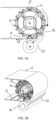
- FIGS. 1A and 1B show a discharge end of a conveyor belt 12 trained around a reversing element, shown as a sprocket 14.
- the reversing element can be any suitable belt-guiding member, including a roller.
- the illustrative conveyor belt 12 comprises a positively-driven, low tension conveyor belt, such as the ThermoDrive ® belt available from Intralox, L.L.C., the Cleandrive positive drive belt available from Habasit AG, the Gates Mectrol PosiClean ® positive drive belt available from Gates Mectrol, the Volta SuperDrive TM and other positive drive belts available from Volta Belting and other positively-driven, low tension conveyor belts known in the art.
- ThermoDrive ® belt available from Intralox, L.L.C.
- the Cleandrive positive drive belt available from Habasit AG
- the Gates Mectrol PosiClean ® positive drive belt available from Gates Mectrol
- the conveyor belt is not limited to these belts, and may be implemented with any suitable positive-drive, low tension conveyor belt as well as any tensioned flat belt.
- the illustrative conveyor belt has a smooth outer surface substantially free of discontinuities and an inner surface with a plurality of drive elements, shown as teeth 13, at a given belt pitch.
- the conveyor belt 12 conveys products along a carryway and returns along a returnway below the carryway.
- the illustrative sprocket 14 comprises a plurality of drive elements, shown as teeth 15, for engaging drive elements 13 on the conveyor belt 12.
- the sprocket 14 is mounted on a rotatable shaft 16.
- the sprocket 14 may be a drive sprocket or an idle sprocket. Other suitable means for driving the belt may be used.
- the conveyor belt 12 reverses direction, guided by the sprocket 14.
- a self-biasing scraper 20 is biased into contact with the conveyor belt 12.
- the scraper 20 removes material from the outer surface of the conveyor belt as the belt moves over the sprocket or other belt guiding member.
- the self-biasing scraper 20 is mounted on a shaft 18 below the sprocket 14.
- the self-biasing scraper 20 comprises a base 22 having a central opening 24 for receiving the shaft 18.
- the illustrative base 22 is cylindrical or tubular, though the invention is not so limited. Alternatively, the base can be open and clamp onto the shaft 18 as in FIGS. 9A - 9B .
- the base 22 forms a top surface 26 that contacts the conveyor belt outer surface at bottom location 50, which is shown as 180° from the top (0°) of the sprocket, though the invention is not limited to be positioned at this location.
- the top surface 26 is formed by a protrusion, bulge or other feature on the base 22 and can be concave, convex, or other complex geometries deemed appropriate.
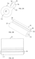
- a tapering scraper tip 30 extends from the base 22.
- the tapering scraper tip forms a scraping edge 32 that contacts the outer surface of the conveyor belt 12 at a second location 52 to scrap away product and debris.
- the illustrative second location 52 is about 135 ⁇ from the top of the sprocket, though the invention is not so limited and the second point of contact can be any suitable location on the belt.
- the tip 30 includes a bar portion 34 extending at an angle from the base 22 towards the front of the sprocket 14.
- the illustrative bar portion has a substantially consistent cross-section, though the invention is not so limited.
- the illustrative bar portion 34 extends perpendicular to the base 22, but the angle of the bar portion relative to the base can be any suitable angle.
- the end 36 of the bar portion 34 bends slightly upwards and tapers to form the scraping edge 32.
- the illustrative scraping edge is linear, though alternatively, the scraping edge can be nonlinear.
- the self-biasing scraper 20 is mounted on the shaft 18 so that the top surface 26 contacts the outer surface of the conveyor belt 12 at location 50.
- the contact between the outer surface of the conveyor belt 12 and the top surface 26 causes the base 22 to rotate on the shaft 18 in direction 38, which pushes the scraping edge 32 into contact with the outer surface of the conveyor belt at the second location 52.
- the scraper 20 self-adjusts to maintain contact with the conveyor belt outer surface at location 52.
- the drag by the belt sliding over the base 22 provides uniform tension, ensuring that the scraper tip 32 conforms to the belt surface for better scraping performance.
- the illustrative scraper tip 30 is integral with the base 22, but the scraper tip or a portion thereof may be removable and-or replaceable.
- the scraper tip 30 may also or alternatively be formed of a different material than the base, or coated in a different material to optimize scraping.
- the base portion 22 may function as a position limiter to ensure engagement of a driven tooth with a sprocket.
- Position limiters such as described in US Patent Number 7,850,562 , may be used in low tension, positive drive belting systems to ensure proper engagement of the belt and drive sprocket by controlling the position of the belt during the drive tooth hand-off process.
- the sprocket effectively drives only one tooth of the sprocket at a time, except for the duration in which a leading driven tooth disengages from the sprocket and hands off to the immediately trailing tooth as the trailing tooth becomes the leading driven tooth.
- the use of a position limiter helps control this handoff by ensuring proper engagement between the belt and corresponding sprocket.
- the base portion 22 is placed a select distance away from the sprocket 14 to force the driven tooth into the sprocket pocket and into engagement with the driver elements of the sprocket.
- the position of the shaft 18 may be variable to ensure proper engagement and positioning of the self-biasing scraper 20.
- the self-biasing scraper 20 is not limited to a round base as shown.
- the base portion 22 may have any suitable size, shape, position or configuration to ensure engagement of the drive belt with the sprocket and proper contact between the scraper tip and belt when the belt is moving.
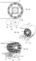
- a self-biasing scraper 120 may include a counter weight 170 for increased tensioning of the scraper tip.
- the illustrative counter weight 170 comprises a central bar 171 and end discs 172.
- the scraper 120 includes arms 173 extending from the base 122 substantially opposite the tapering scraper blade tip 130 for receiving the central bar 171. As shown in FIGS. 4A and 4B , the arms 173 include rounded tips 174 forming channels 175 for seating the counter weight central bar 171.
- Arms 173 and the scraper blade tip 130 form a lever system pivoting about the shaft 118, where the weight of the counter weight 170 is transmitted through the arms 173 and the tip 130 to the edge 132 to increase the pressure between the scraper edge 132 and the belt for improved scraping performance.
- the illustrative arms 173 take the shape of bars but the arms 173 can be any shape and dimensions to take the advantage of a lever system.
- the self-biasing scraper in FIGS. 4A and 4B also includes cut outs 135 in the scraper tip 130 to facilitate cleaning and -or to make the scraper tip 130 lighter.
- the scraper tip 130 and arms 173 are slightly less than 180 ⁇ apart.
- a self-biasing scraper 220 with a tapering scraper tip 230 may include a single, solid arm 273 forming a continuous channel 275 for receiving a counter weight.
- a self-biasing scraper 320 with a tapering scraper tip 330 may include an integral counter weight 370.
- the counter weight 370 can be a solid plastic bar connected to the scraper base 322 by arms 373.
- the counter weight 370 may have inserted rods made from materials such as stainless steel that are not visible from the outside.
- the illustrative counter weight 370 has the shape of a bar, but the counter weight 370 can be any shapes and may be made from the same or different materials as the base 322.
- the scraper tip 330 and the counter weight 370 are slightly less than 180 ⁇ apart.
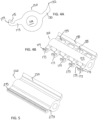
- a self-biasing scraper 420 may be designed to receive snap-on position limiters.
- the self-biasing scraper 420 is mounted on a longitudinal mounting bar 480 within the base portion 422.
- the longitudinal mounting bar 480 has a longitudinal channel 481 on an outer surface and notches 482.
- a tapering scraper tip 430 extends from the base portion 422.
- the scraper 420 further includes arms 473 for holding a counter weight 470, which may alternatively be integrally formed with the rest of the scraper.
- the scraper tip 430 includes openings 438 exposing the bar 480.
- a plurality of snap-on position limiters 500 may be mounted to the scraper 420.
- the illustrative position limiters 500 comprise a limiting surface 520 facing the conveyor belt for ensuring proper engagement of the sprocket and conveyor belt.
- the base of the position limiter forms a snap clamp for engaging the bar 480.
- Each position limiter 500 fits into an opening 438 to snap onto the mounting bar 480.
- the illustrative mounting bar 480 includes a longitudinal channel 481 and notches 482 for engaging corresponding features on the position limiter snap clamp.
- FIG. 8B is a bottom view of the self-biasing scraper 420, with the position limiters 500 snapped into place.
- FIG. 8C is a side view of the self-biasing scraper 420, with position limiters 500 snapped into place.
- the scraper 420 can rotate freely about the shaft 480 without interfering with the limiter 500, as shown in FIG. 8D .
- FIGS. 9A and 9B show another self-biasing scraper 620 including a tapering scraper tip 630 and an integral counter weight 670 extending from a base 622.
- the base 622 can be an open segment of a tube that can receive a mounting bar via an opening 624 in the base 622.
- the top of the base 622 contacts a moving conveyor belt at a first location to bias the tip 630 into contact with an outer surface of the conveyor belt at a second location.
Landscapes
- Engineering & Computer Science (AREA)
- Mechanical Engineering (AREA)
- Structure Of Belt Conveyors (AREA)
- Chain Conveyers (AREA)
- Branching, Merging, And Special Transfer Between Conveyors (AREA)
Claims (6)
- Selbstspannender Abstreifer (420) für ein Förderband (12), umfassend:Eine Basis (422), die eine Öffnung zur Aufnahme einer Welle (480) umfasst und eine Oberseite zum Kontaktieren des Förderbands (12) in einer ersten Position (50) aufweist; undeine sich verjüngende Abstreiferspitze (430), die sich aus der Basis (422) erstreckt, wobei die Spitze (430) zum Kontaktieren des Förderbands (12) an einer zweiten Stelle (52) dient, wobei die sich verjüngende Abstreiferspitze (430) Öffnungen (438) aufweist, welche die Welle (480) freilegen jeweils zur Aufnahme und Montage eines Positionsbegrenzers (500) auf die Welle (480), dadurch gekennzeichnet, dass die Welle (480) einen Längskanal (481) auf einer Außenfläche und Kerben (482) zur Montage des Positionsbegrenzers (500) umfasst, wobei ferner Positionsbegrenzer (500) umfassend, die jeweils in eine die Welle freilegende Öffnung (438) montiert und auf die Welle (480) geschnappt sind.
- Abstreifer (420) nach Anspruch 1, wobei die sich verjüngende Abstreiferspitze (430) einen Steg, der sich in einem ausgewählten Winkel aus der Basis (422) erstreckt und ein Ende umfasst, das sich aus dem Steg nach oben biegt, wobei sich das Ende verjüngt, um eine Abstreiferkante zu bilden.
- Abstreifer (420) nach Anspruch 1, der ferner ein Gegengewicht (470) umfasst, das an die Basis (422) gekoppelt ist.
- Abstreifer (420) nach Anspruch 3, der ferner einen sich aus der Basis erstreckenden Arm (473) zur Aufnahme des Gegengewichts umfasst.
- Abstreifer (420) nach Anspruch 3, wobei das Gegengewicht (470) integral mit der Basis (422) ist.
- Abstreifer nach Anspruch 1, wobei die Basis (422) im Wesentlichen röhrenförmig ist.
Applications Claiming Priority (2)
| Application Number | Priority Date | Filing Date | Title |
|---|---|---|---|
| US201562185845P | 2015-06-29 | 2015-06-29 | |
| PCT/US2016/037507 WO2017003686A1 (en) | 2015-06-29 | 2016-06-15 | Self-biasing scraper for a conveyor belt |
Publications (3)
| Publication Number | Publication Date |
|---|---|
| EP3313758A1 EP3313758A1 (de) | 2018-05-02 |
| EP3313758A4 EP3313758A4 (de) | 2019-03-06 |
| EP3313758B1 true EP3313758B1 (de) | 2025-05-21 |
Family
ID=57601805
Family Applications (1)
| Application Number | Title | Priority Date | Filing Date |
|---|---|---|---|
| EP16818444.8A Active EP3313758B1 (de) | 2015-06-29 | 2016-06-15 | Selbstspannender abstreifer für ein förderband |
Country Status (10)
| Country | Link |
|---|---|
| US (1) | US9840374B2 (de) |
| EP (1) | EP3313758B1 (de) |
| CN (1) | CN107922126A (de) |
| AU (1) | AU2016285715B2 (de) |
| BR (1) | BR112017028080B1 (de) |
| DK (1) | DK3313758T3 (de) |
| ES (1) | ES3027192T3 (de) |
| MX (1) | MX2018000046A (de) |
| PL (1) | PL3313758T3 (de) |
| WO (1) | WO2017003686A1 (de) |
Families Citing this family (7)
| Publication number | Priority date | Publication date | Assignee | Title |
|---|---|---|---|---|
| RU2733930C1 (ru) * | 2017-08-04 | 2020-10-08 | ДжФЕ СТИЛ КОРПОРЕЙШН | Роликовый скребок |
| JP7356422B2 (ja) * | 2017-12-13 | 2023-10-04 | レイトラム,エル.エル.シー. | 衛生的中空フレームアセンブリ |
| JP7354128B2 (ja) * | 2018-03-22 | 2023-10-02 | レイトラム,エル.エル.シー. | フライト付きコンベヤベルト用の位置制限装置 |
| DK3972918T3 (da) * | 2019-05-20 | 2025-06-30 | Laitram Llc | Drivanordning til transportør |
| CN112455310B (zh) * | 2021-02-04 | 2021-07-30 | 山东交通职业学院 | 一种用于半挂车的倾卸用输送机及倾卸方法 |
| IT202100033068A1 (it) * | 2021-12-30 | 2023-06-30 | Siderurgica Del Polesine S R L | Dispositivo per la filtrazione di un liquido |
| CN115339238A (zh) * | 2022-09-16 | 2022-11-15 | 凤阳科力广告传媒有限公司 | 一种新型可定时的自动胶印控制系统及方法 |
Family Cites Families (28)
| Publication number | Priority date | Publication date | Assignee | Title |
|---|---|---|---|---|
| US3722667A (en) * | 1971-06-14 | 1973-03-27 | L Olson | Dual wiping device for a conveyor belt in which both wipers have a common pivotal support but operate independently of each other |
| US4269301A (en) * | 1979-10-22 | 1981-05-26 | Gibbs Alfred S | Conveyor belt scraper system |
| US4402394A (en) * | 1981-07-27 | 1983-09-06 | Stoll Donald L | Conveyor belt scraper |
| US4953689A (en) * | 1986-09-02 | 1990-09-04 | Martin Engineering Company | Conveyor belt cleaner |
| US5016746A (en) * | 1988-06-20 | 1991-05-21 | Asgco Manufacturing, Inc. | Conveyor belt scraping apparatus |
| US4969553A (en) * | 1990-02-08 | 1990-11-13 | Richwood Industries, Inc. | Belt scraper with gear adjustment |
| GB9221426D0 (en) * | 1992-10-13 | 1992-11-25 | Morin Normand J | Conveyor belt scraper |
| DK0629171T3 (da) * | 1992-10-13 | 1999-02-01 | Schwarze Hans Otto | Afstrygningselement til anbringelse på en systembærer af en afstrygningsindretning |
| DE9400258U1 (de) * | 1994-01-12 | 1995-05-18 | Schwarze, Hans-Otto, 45665 Recklinghausen | Vorrichtung zum Abstreifen von Verunreinigungen von Gurtbändern im Bereich einer Antriebs- oder Umlenkrolle |
| US6076656A (en) * | 1995-10-13 | 2000-06-20 | Mat; Ghislain Justin Marie | Conveyor belt scrapers |
| US5887702A (en) * | 1995-10-27 | 1999-03-30 | Asgco Manufacturing, Inc. | Trailing arm secondary belt cleaner |
| US6374991B1 (en) * | 1999-03-19 | 2002-04-23 | Martin Engineering Company | Conveyor belt cleaner and tensioner assembly |
| US20060049023A1 (en) * | 2004-09-09 | 2006-03-09 | Dietsch Phillip E | Rotary conveyor belt cleaner |
| US7051862B1 (en) * | 2004-12-17 | 2006-05-30 | Richwood Industries, Inc. | Conveyor belt cleaner assembly including scalper blade |
| CN101132975B (zh) | 2005-01-19 | 2012-06-27 | 热驱动有限责任公司 | 低摩擦、直接驱动的传送器带 |
| US20070179002A1 (en) | 2006-02-01 | 2007-08-02 | Mol Belting Company | Conveyor with roller on belt return span |
| US8167114B2 (en) | 2008-01-03 | 2012-05-01 | Souhel Khanania | System and method for product removal |
| US7987966B2 (en) * | 2008-04-10 | 2011-08-02 | Flexible Steel Lacing Company | Removable cartridge cleaner |
| US7819237B2 (en) * | 2009-03-16 | 2010-10-26 | Superior Industries, Llc | Belt scraper tensioning assembly |
| DE102010030620B4 (de) * | 2010-06-28 | 2020-10-15 | Rema Tip Top Ag | Segmentkörper für einen Fördergurtabstreifer |
| US8875870B2 (en) * | 2011-03-31 | 2014-11-04 | Benetech, Inc. | Conveyor belt cleaner scraper blade and assembly |
| BR112014016034A8 (pt) | 2012-01-09 | 2017-07-04 | Tega Ind Ltd | engaste de raspador de correia aperfeiçoado |
| US8776990B2 (en) | 2012-01-24 | 2014-07-15 | Superior Industries, Inc. | Dual belt cleaner |
| US8869970B2 (en) * | 2012-11-05 | 2014-10-28 | Laitram, L.L.C. | Tapered scraper for a conveyor belt |
| DE102013006821B4 (de) * | 2013-01-07 | 2016-05-04 | Hans-Otto Schwarze | Gurtabstreifer mit Winkelhöhenverstellung |
| US10077156B2 (en) * | 2014-01-24 | 2018-09-18 | Laitram, L.L.C. | Snap-on position limiter for a conveyor belt |
| CA2935726C (en) * | 2014-01-24 | 2022-11-29 | Laitram, L.L.C. | Snap-on position limiter for a conveyor belt |
| US9340366B2 (en) * | 2014-08-22 | 2016-05-17 | Martin Engineering Company | Bulk material conveyor belt scraper and method of forming the same |
-
2016
- 2016-06-15 ES ES16818444T patent/ES3027192T3/es active Active
- 2016-06-15 WO PCT/US2016/037507 patent/WO2017003686A1/en not_active Ceased
- 2016-06-15 EP EP16818444.8A patent/EP3313758B1/de active Active
- 2016-06-15 AU AU2016285715A patent/AU2016285715B2/en active Active
- 2016-06-15 US US15/182,832 patent/US9840374B2/en active Active
- 2016-06-15 PL PL16818444.8T patent/PL3313758T3/pl unknown
- 2016-06-15 MX MX2018000046A patent/MX2018000046A/es unknown
- 2016-06-15 CN CN201680037973.XA patent/CN107922126A/zh active Pending
- 2016-06-15 BR BR112017028080-9A patent/BR112017028080B1/pt active IP Right Grant
- 2016-06-15 DK DK16818444.8T patent/DK3313758T3/da active
Also Published As
| Publication number | Publication date |
|---|---|
| WO2017003686A1 (en) | 2017-01-05 |
| ES3027192T3 (en) | 2025-06-13 |
| EP3313758A1 (de) | 2018-05-02 |
| AU2016285715A1 (en) | 2017-12-21 |
| DK3313758T3 (da) | 2025-06-16 |
| BR112017028080A2 (pt) | 2018-08-28 |
| CN107922126A (zh) | 2018-04-17 |
| US9840374B2 (en) | 2017-12-12 |
| EP3313758A4 (de) | 2019-03-06 |
| AU2016285715B2 (en) | 2020-11-26 |
| PL3313758T3 (pl) | 2025-06-23 |
| MX2018000046A (es) | 2018-05-28 |
| US20160376108A1 (en) | 2016-12-29 |
| BR112017028080B1 (pt) | 2022-08-02 |
Similar Documents
| Publication | Publication Date | Title |
|---|---|---|
| EP3313758B1 (de) | Selbstspannender abstreifer für ein förderband | |
| EP3097030B1 (de) | Einrastbarer positionsbegrenzer für ein förderband | |
| US10427880B2 (en) | Snap-on position limiter for a conveyor belt | |
| EP3515845B1 (de) | Zuführungs- und abführungsanordnungen für einen förderer | |
| US10035656B2 (en) | Infeed and outfeed assemblies for a conveyor | |
| KR20110058514A (ko) | 식육슬라이서 | |
| US8042679B2 (en) | Belt cleaner | |
| KR101814279B1 (ko) | 컨베이어벨트 크리닝 장치 | |
| WO2018111743A1 (en) | Snap-on position limiter for a conveyor belt | |
| EP2914519B1 (de) | Sich verjüngender abstreifer für ein förderband | |
| US20200406490A1 (en) | Longitudinal cutting of a band of a soft food mass | |
| US4422216A (en) | Device for separating meat from bones | |
| KR101238882B1 (ko) | 밸트 콘베이어의 밸트 청소 장치 | |
| KR102573053B1 (ko) | 식자재 절단장치 | |
| JP2008245549A (ja) | カッタ装置 | |
| EP3768617B1 (de) | Positionsbegrenzer für ein stollenförderband | |
| KR20210148300A (ko) | 안내 장치 | |
| SE450628B (sv) | Skerpdon for en saganordning |
Legal Events
| Date | Code | Title | Description |
|---|---|---|---|
| STAA | Information on the status of an ep patent application or granted ep patent |
Free format text: STATUS: THE INTERNATIONAL PUBLICATION HAS BEEN MADE |
|
| PUAI | Public reference made under article 153(3) epc to a published international application that has entered the european phase |
Free format text: ORIGINAL CODE: 0009012 |
|
| STAA | Information on the status of an ep patent application or granted ep patent |
Free format text: STATUS: REQUEST FOR EXAMINATION WAS MADE |
|
| 17P | Request for examination filed |
Effective date: 20171207 |
|
| AK | Designated contracting states |
Kind code of ref document: A1 Designated state(s): AL AT BE BG CH CY CZ DE DK EE ES FI FR GB GR HR HU IE IS IT LI LT LU LV MC MK MT NL NO PL PT RO RS SE SI SK SM TR |
|
| AX | Request for extension of the european patent |
Extension state: BA ME |
|
| DAV | Request for validation of the european patent (deleted) | ||
| DAX | Request for extension of the european patent (deleted) | ||
| A4 | Supplementary search report drawn up and despatched |
Effective date: 20190201 |
|
| RIC1 | Information provided on ipc code assigned before grant |
Ipc: B08B 1/00 20060101ALI20190128BHEP Ipc: B08B 1/02 20060101ALI20190128BHEP Ipc: B65G 45/16 20060101AFI20190128BHEP |
|
| STAA | Information on the status of an ep patent application or granted ep patent |
Free format text: STATUS: EXAMINATION IS IN PROGRESS |
|
| 17Q | First examination report despatched |
Effective date: 20200828 |
|
| REG | Reference to a national code |
Ref country code: DE Ref legal event code: R079 Free format text: PREVIOUS MAIN CLASS: B65G0045120000 Ipc: B65G0045160000 Ref country code: DE Ref legal event code: R079 Ref document number: 602016092328 Country of ref document: DE Free format text: PREVIOUS MAIN CLASS: B65G0045120000 Ipc: B65G0045160000 |
|
| GRAP | Despatch of communication of intention to grant a patent |
Free format text: ORIGINAL CODE: EPIDOSNIGR1 |
|
| STAA | Information on the status of an ep patent application or granted ep patent |
Free format text: STATUS: GRANT OF PATENT IS INTENDED |
|
| RIC1 | Information provided on ipc code assigned before grant |
Ipc: B08B 1/16 20240101ALI20241119BHEP Ipc: B65G 45/16 20060101AFI20241119BHEP |
|
| INTG | Intention to grant announced |
Effective date: 20241217 |
|
| GRAS | Grant fee paid |
Free format text: ORIGINAL CODE: EPIDOSNIGR3 |
|
| GRAA | (expected) grant |
Free format text: ORIGINAL CODE: 0009210 |
|
| STAA | Information on the status of an ep patent application or granted ep patent |
Free format text: STATUS: THE PATENT HAS BEEN GRANTED |
|
| P01 | Opt-out of the competence of the unified patent court (upc) registered |
Free format text: CASE NUMBER: APP_12889/2025 Effective date: 20250314 |
|
| AK | Designated contracting states |
Kind code of ref document: B1 Designated state(s): AL AT BE BG CH CY CZ DE DK EE ES FI FR GB GR HR HU IE IS IT LI LT LU LV MC MK MT NL NO PL PT RO RS SE SI SK SM TR |
|
| REG | Reference to a national code |
Ref country code: GB Ref legal event code: FG4D |
|
| REG | Reference to a national code |
Ref country code: CH Ref legal event code: EP |
|
| REG | Reference to a national code |
Ref country code: NL Ref legal event code: FP |
|
| REG | Reference to a national code |
Ref country code: DE Ref legal event code: R096 Ref document number: 602016092328 Country of ref document: DE |
|
| REG | Reference to a national code |
Ref country code: ES Ref legal event code: FG2A Ref document number: 3027192 Country of ref document: ES Kind code of ref document: T3 Effective date: 20250613 |
|
| REG | Reference to a national code |
Ref country code: DK Ref legal event code: T3 Effective date: 20250610 |
|
| PGFP | Annual fee paid to national office [announced via postgrant information from national office to epo] |
Ref country code: NL Payment date: 20250528 Year of fee payment: 10 |
|
| REG | Reference to a national code |
Ref country code: IE Ref legal event code: FG4D |
|
| PGFP | Annual fee paid to national office [announced via postgrant information from national office to epo] |
Ref country code: PL Payment date: 20250529 Year of fee payment: 10 Ref country code: DE Payment date: 20250526 Year of fee payment: 10 |
|
| PGFP | Annual fee paid to national office [announced via postgrant information from national office to epo] |
Ref country code: GB Payment date: 20250528 Year of fee payment: 10 Ref country code: DK Payment date: 20250613 Year of fee payment: 10 |
|
| PGFP | Annual fee paid to national office [announced via postgrant information from national office to epo] |
Ref country code: FR Payment date: 20250528 Year of fee payment: 10 |
|
| PG25 | Lapsed in a contracting state [announced via postgrant information from national office to epo] |
Ref country code: PT Free format text: LAPSE BECAUSE OF FAILURE TO SUBMIT A TRANSLATION OF THE DESCRIPTION OR TO PAY THE FEE WITHIN THE PRESCRIBED TIME-LIMIT Effective date: 20250922 Ref country code: FI Free format text: LAPSE BECAUSE OF FAILURE TO SUBMIT A TRANSLATION OF THE DESCRIPTION OR TO PAY THE FEE WITHIN THE PRESCRIBED TIME-LIMIT Effective date: 20250521 |
|
| PGFP | Annual fee paid to national office [announced via postgrant information from national office to epo] |
Ref country code: ES Payment date: 20250709 Year of fee payment: 10 |
|
| REG | Reference to a national code |
Ref country code: LT Ref legal event code: MG9D |
|
| PG25 | Lapsed in a contracting state [announced via postgrant information from national office to epo] |
Ref country code: NO Free format text: LAPSE BECAUSE OF FAILURE TO SUBMIT A TRANSLATION OF THE DESCRIPTION OR TO PAY THE FEE WITHIN THE PRESCRIBED TIME-LIMIT Effective date: 20250821 Ref country code: GR Free format text: LAPSE BECAUSE OF FAILURE TO SUBMIT A TRANSLATION OF THE DESCRIPTION OR TO PAY THE FEE WITHIN THE PRESCRIBED TIME-LIMIT Effective date: 20250822 |
|
| PGFP | Annual fee paid to national office [announced via postgrant information from national office to epo] |
Ref country code: TR Payment date: 20250814 Year of fee payment: 10 Ref country code: IT Payment date: 20250527 Year of fee payment: 10 |
|
| PG25 | Lapsed in a contracting state [announced via postgrant information from national office to epo] |
Ref country code: BG Free format text: LAPSE BECAUSE OF FAILURE TO SUBMIT A TRANSLATION OF THE DESCRIPTION OR TO PAY THE FEE WITHIN THE PRESCRIBED TIME-LIMIT Effective date: 20250521 |
|
| PG25 | Lapsed in a contracting state [announced via postgrant information from national office to epo] |
Ref country code: HR Free format text: LAPSE BECAUSE OF FAILURE TO SUBMIT A TRANSLATION OF THE DESCRIPTION OR TO PAY THE FEE WITHIN THE PRESCRIBED TIME-LIMIT Effective date: 20250521 |
|
| PGFP | Annual fee paid to national office [announced via postgrant information from national office to epo] |
Ref country code: CH Payment date: 20250701 Year of fee payment: 10 |
|
| PG25 | Lapsed in a contracting state [announced via postgrant information from national office to epo] |
Ref country code: RS Free format text: LAPSE BECAUSE OF FAILURE TO SUBMIT A TRANSLATION OF THE DESCRIPTION OR TO PAY THE FEE WITHIN THE PRESCRIBED TIME-LIMIT Effective date: 20250821 |
|
| PG25 | Lapsed in a contracting state [announced via postgrant information from national office to epo] |
Ref country code: IS Free format text: LAPSE BECAUSE OF FAILURE TO SUBMIT A TRANSLATION OF THE DESCRIPTION OR TO PAY THE FEE WITHIN THE PRESCRIBED TIME-LIMIT Effective date: 20250921 |
|
| PG25 | Lapsed in a contracting state [announced via postgrant information from national office to epo] |
Ref country code: LV Free format text: LAPSE BECAUSE OF FAILURE TO SUBMIT A TRANSLATION OF THE DESCRIPTION OR TO PAY THE FEE WITHIN THE PRESCRIBED TIME-LIMIT Effective date: 20250521 |
|
| REG | Reference to a national code |
Ref country code: AT Ref legal event code: MK05 Ref document number: 1796594 Country of ref document: AT Kind code of ref document: T Effective date: 20250521 |
|
| PG25 | Lapsed in a contracting state [announced via postgrant information from national office to epo] |
Ref country code: AT Free format text: LAPSE BECAUSE OF FAILURE TO SUBMIT A TRANSLATION OF THE DESCRIPTION OR TO PAY THE FEE WITHIN THE PRESCRIBED TIME-LIMIT Effective date: 20250521 Ref country code: SM Free format text: LAPSE BECAUSE OF FAILURE TO SUBMIT A TRANSLATION OF THE DESCRIPTION OR TO PAY THE FEE WITHIN THE PRESCRIBED TIME-LIMIT Effective date: 20250521 |
|
| PG25 | Lapsed in a contracting state [announced via postgrant information from national office to epo] |
Ref country code: CZ Free format text: LAPSE BECAUSE OF FAILURE TO SUBMIT A TRANSLATION OF THE DESCRIPTION OR TO PAY THE FEE WITHIN THE PRESCRIBED TIME-LIMIT Effective date: 20250521 |
|
| PG25 | Lapsed in a contracting state [announced via postgrant information from national office to epo] |
Ref country code: EE Free format text: LAPSE BECAUSE OF FAILURE TO SUBMIT A TRANSLATION OF THE DESCRIPTION OR TO PAY THE FEE WITHIN THE PRESCRIBED TIME-LIMIT Effective date: 20250521 |
|
| PG25 | Lapsed in a contracting state [announced via postgrant information from national office to epo] |
Ref country code: RO Free format text: LAPSE BECAUSE OF FAILURE TO SUBMIT A TRANSLATION OF THE DESCRIPTION OR TO PAY THE FEE WITHIN THE PRESCRIBED TIME-LIMIT Effective date: 20250521 Ref country code: SK Free format text: LAPSE BECAUSE OF FAILURE TO SUBMIT A TRANSLATION OF THE DESCRIPTION OR TO PAY THE FEE WITHIN THE PRESCRIBED TIME-LIMIT Effective date: 20250521 |
|
| PG25 | Lapsed in a contracting state [announced via postgrant information from national office to epo] |
Ref country code: LU Free format text: LAPSE BECAUSE OF NON-PAYMENT OF DUE FEES Effective date: 20250615 |
|
| PG25 | Lapsed in a contracting state [announced via postgrant information from national office to epo] |
Ref country code: MC Free format text: LAPSE BECAUSE OF FAILURE TO SUBMIT A TRANSLATION OF THE DESCRIPTION OR TO PAY THE FEE WITHIN THE PRESCRIBED TIME-LIMIT Effective date: 20250521 |
|
| REG | Reference to a national code |
Ref country code: DE Ref legal event code: R097 Ref document number: 602016092328 Country of ref document: DE |
|
| REG | Reference to a national code |
Ref country code: BE Ref legal event code: MM Effective date: 20250630 |
|
| PLBE | No opposition filed within time limit |
Free format text: ORIGINAL CODE: 0009261 |
|
| STAA | Information on the status of an ep patent application or granted ep patent |
Free format text: STATUS: NO OPPOSITION FILED WITHIN TIME LIMIT |
|
| REG | Reference to a national code |
Ref country code: CH Ref legal event code: L10 Free format text: ST27 STATUS EVENT CODE: U-0-0-L10-L00 (AS PROVIDED BY THE NATIONAL OFFICE) Effective date: 20260402 |
|
| PG25 | Lapsed in a contracting state [announced via postgrant information from national office to epo] |
Ref country code: IE Free format text: LAPSE BECAUSE OF NON-PAYMENT OF DUE FEES Effective date: 20250615 |
|
| PG25 | Lapsed in a contracting state [announced via postgrant information from national office to epo] |
Ref country code: BE Free format text: LAPSE BECAUSE OF NON-PAYMENT OF DUE FEES Effective date: 20250630 |