EP3313645B1 - Vorrichtung zur bearbeitung, insbesondere zur ultraschallverschweissung, von packungsmänteln sowie verwendung der vorrichtung - Google Patents
Vorrichtung zur bearbeitung, insbesondere zur ultraschallverschweissung, von packungsmänteln sowie verwendung der vorrichtung Download PDFInfo
- Publication number
- EP3313645B1 EP3313645B1 EP16729833.0A EP16729833A EP3313645B1 EP 3313645 B1 EP3313645 B1 EP 3313645B1 EP 16729833 A EP16729833 A EP 16729833A EP 3313645 B1 EP3313645 B1 EP 3313645B1
- Authority
- EP
- European Patent Office
- Prior art keywords
- parallel
- gap
- packaging
- tools
- anvil
- Prior art date
- Legal status (The legal status is an assumption and is not a legal conclusion. Google has not performed a legal analysis and makes no representation as to the accuracy of the status listed.)
- Active
Links
Images



Classifications
-
- B—PERFORMING OPERATIONS; TRANSPORTING
- B65—CONVEYING; PACKING; STORING; HANDLING THIN OR FILAMENTARY MATERIAL
- B65B—MACHINES, APPARATUS OR DEVICES FOR, OR METHODS OF, PACKAGING ARTICLES OR MATERIALS; UNPACKING
- B65B51/00—Devices for, or methods of, sealing or securing package folds or closures; Devices for gathering or twisting wrappers, or necks of bags
- B65B51/10—Applying or generating heat or pressure or combinations thereof
- B65B51/22—Applying or generating heat or pressure or combinations thereof by friction or ultrasonic or high-frequency electrical means
- B65B51/225—Applying or generating heat or pressure or combinations thereof by friction or ultrasonic or high-frequency electrical means by ultrasonic welding
-
- B—PERFORMING OPERATIONS; TRANSPORTING
- B29—WORKING OF PLASTICS; WORKING OF SUBSTANCES IN A PLASTIC STATE IN GENERAL
- B29C—SHAPING OR JOINING OF PLASTICS; SHAPING OF MATERIAL IN A PLASTIC STATE, NOT OTHERWISE PROVIDED FOR; AFTER-TREATMENT OF THE SHAPED PRODUCTS, e.g. REPAIRING
- B29C65/00—Joining or sealing of preformed parts, e.g. welding of plastics materials; Apparatus therefor
- B29C65/02—Joining or sealing of preformed parts, e.g. welding of plastics materials; Apparatus therefor by heating, with or without pressure
- B29C65/08—Joining or sealing of preformed parts, e.g. welding of plastics materials; Apparatus therefor by heating, with or without pressure using ultrasonic vibrations
- B29C65/083—Joining or sealing of preformed parts, e.g. welding of plastics materials; Apparatus therefor by heating, with or without pressure using ultrasonic vibrations using a rotary sonotrode or a rotary anvil
- B29C65/087—Joining or sealing of preformed parts, e.g. welding of plastics materials; Apparatus therefor by heating, with or without pressure using ultrasonic vibrations using a rotary sonotrode or a rotary anvil using both a rotary sonotrode and a rotary anvil
-
- B—PERFORMING OPERATIONS; TRANSPORTING
- B29—WORKING OF PLASTICS; WORKING OF SUBSTANCES IN A PLASTIC STATE IN GENERAL
- B29C—SHAPING OR JOINING OF PLASTICS; SHAPING OF MATERIAL IN A PLASTIC STATE, NOT OTHERWISE PROVIDED FOR; AFTER-TREATMENT OF THE SHAPED PRODUCTS, e.g. REPAIRING
- B29C65/00—Joining or sealing of preformed parts, e.g. welding of plastics materials; Apparatus therefor
- B29C65/78—Means for handling the parts to be joined, e.g. for making containers or hollow articles, e.g. means for handling sheets, plates, web-like materials, tubular articles, hollow articles or elements to be joined therewith; Means for discharging the joined articles from the joining apparatus
- B29C65/7841—Holding or clamping means for handling purposes
-
- B—PERFORMING OPERATIONS; TRANSPORTING
- B29—WORKING OF PLASTICS; WORKING OF SUBSTANCES IN A PLASTIC STATE IN GENERAL
- B29C—SHAPING OR JOINING OF PLASTICS; SHAPING OF MATERIAL IN A PLASTIC STATE, NOT OTHERWISE PROVIDED FOR; AFTER-TREATMENT OF THE SHAPED PRODUCTS, e.g. REPAIRING
- B29C66/00—General aspects of processes or apparatus for joining preformed parts
- B29C66/01—General aspects dealing with the joint area or with the area to be joined
- B29C66/05—Particular design of joint configurations
- B29C66/10—Particular design of joint configurations particular design of the joint cross-sections
- B29C66/11—Joint cross-sections comprising a single joint-segment, i.e. one of the parts to be joined comprising a single joint-segment in the joint cross-section
- B29C66/112—Single lapped joints
-
- B—PERFORMING OPERATIONS; TRANSPORTING
- B29—WORKING OF PLASTICS; WORKING OF SUBSTANCES IN A PLASTIC STATE IN GENERAL
- B29C—SHAPING OR JOINING OF PLASTICS; SHAPING OF MATERIAL IN A PLASTIC STATE, NOT OTHERWISE PROVIDED FOR; AFTER-TREATMENT OF THE SHAPED PRODUCTS, e.g. REPAIRING
- B29C66/00—General aspects of processes or apparatus for joining preformed parts
- B29C66/01—General aspects dealing with the joint area or with the area to be joined
- B29C66/05—Particular design of joint configurations
- B29C66/10—Particular design of joint configurations particular design of the joint cross-sections
- B29C66/11—Joint cross-sections comprising a single joint-segment, i.e. one of the parts to be joined comprising a single joint-segment in the joint cross-section
- B29C66/112—Single lapped joints
- B29C66/1122—Single lap to lap joints, i.e. overlap joints
-
- B—PERFORMING OPERATIONS; TRANSPORTING
- B29—WORKING OF PLASTICS; WORKING OF SUBSTANCES IN A PLASTIC STATE IN GENERAL
- B29C—SHAPING OR JOINING OF PLASTICS; SHAPING OF MATERIAL IN A PLASTIC STATE, NOT OTHERWISE PROVIDED FOR; AFTER-TREATMENT OF THE SHAPED PRODUCTS, e.g. REPAIRING
- B29C66/00—General aspects of processes or apparatus for joining preformed parts
- B29C66/01—General aspects dealing with the joint area or with the area to be joined
- B29C66/05—Particular design of joint configurations
- B29C66/10—Particular design of joint configurations particular design of the joint cross-sections
- B29C66/13—Single flanged joints; Fin-type joints; Single hem joints; Edge joints; Interpenetrating fingered joints; Other specific particular designs of joint cross-sections not provided for in groups B29C66/11 - B29C66/12
- B29C66/135—Single hemmed joints, i.e. one of the parts to be joined being hemmed in the joint area
-
- B—PERFORMING OPERATIONS; TRANSPORTING
- B29—WORKING OF PLASTICS; WORKING OF SUBSTANCES IN A PLASTIC STATE IN GENERAL
- B29C—SHAPING OR JOINING OF PLASTICS; SHAPING OF MATERIAL IN A PLASTIC STATE, NOT OTHERWISE PROVIDED FOR; AFTER-TREATMENT OF THE SHAPED PRODUCTS, e.g. REPAIRING
- B29C66/00—General aspects of processes or apparatus for joining preformed parts
- B29C66/01—General aspects dealing with the joint area or with the area to be joined
- B29C66/346—Making joints having variable thicknesses in the joint area, e.g. by using jaws having an adapted configuration
-
- B—PERFORMING OPERATIONS; TRANSPORTING
- B29—WORKING OF PLASTICS; WORKING OF SUBSTANCES IN A PLASTIC STATE IN GENERAL
- B29C—SHAPING OR JOINING OF PLASTICS; SHAPING OF MATERIAL IN A PLASTIC STATE, NOT OTHERWISE PROVIDED FOR; AFTER-TREATMENT OF THE SHAPED PRODUCTS, e.g. REPAIRING
- B29C66/00—General aspects of processes or apparatus for joining preformed parts
- B29C66/40—General aspects of joining substantially flat articles, e.g. plates, sheets or web-like materials; Making flat seams in tubular or hollow articles; Joining single elements to substantially flat surfaces
- B29C66/41—Joining substantially flat articles ; Making flat seams in tubular or hollow articles
- B29C66/43—Joining a relatively small portion of the surface of said articles
- B29C66/431—Joining the articles to themselves
- B29C66/4312—Joining the articles to themselves for making flat seams in tubular or hollow articles, e.g. transversal seams
- B29C66/43121—Closing the ends of tubular or hollow single articles, e.g. closing the ends of bags
- B29C66/43122—Closing the top of gable top containers
-
- B—PERFORMING OPERATIONS; TRANSPORTING
- B29—WORKING OF PLASTICS; WORKING OF SUBSTANCES IN A PLASTIC STATE IN GENERAL
- B29C—SHAPING OR JOINING OF PLASTICS; SHAPING OF MATERIAL IN A PLASTIC STATE, NOT OTHERWISE PROVIDED FOR; AFTER-TREATMENT OF THE SHAPED PRODUCTS, e.g. REPAIRING
- B29C66/00—General aspects of processes or apparatus for joining preformed parts
- B29C66/80—General aspects of machine operations or constructions and parts thereof
- B29C66/81—General aspects of the pressing elements, i.e. the elements applying pressure on the parts to be joined in the area to be joined, e.g. the welding jaws or clamps
- B29C66/816—General aspects of the pressing elements, i.e. the elements applying pressure on the parts to be joined in the area to be joined, e.g. the welding jaws or clamps characterised by the mounting of the pressing elements, e.g. of the welding jaws or clamps
- B29C66/8161—General aspects of the pressing elements, i.e. the elements applying pressure on the parts to be joined in the area to be joined, e.g. the welding jaws or clamps characterised by the mounting of the pressing elements, e.g. of the welding jaws or clamps said pressing elements being supported or backed-up by springs or by resilient material
-
- B—PERFORMING OPERATIONS; TRANSPORTING
- B29—WORKING OF PLASTICS; WORKING OF SUBSTANCES IN A PLASTIC STATE IN GENERAL
- B29C—SHAPING OR JOINING OF PLASTICS; SHAPING OF MATERIAL IN A PLASTIC STATE, NOT OTHERWISE PROVIDED FOR; AFTER-TREATMENT OF THE SHAPED PRODUCTS, e.g. REPAIRING
- B29C66/00—General aspects of processes or apparatus for joining preformed parts
- B29C66/80—General aspects of machine operations or constructions and parts thereof
- B29C66/81—General aspects of the pressing elements, i.e. the elements applying pressure on the parts to be joined in the area to be joined, e.g. the welding jaws or clamps
- B29C66/816—General aspects of the pressing elements, i.e. the elements applying pressure on the parts to be joined in the area to be joined, e.g. the welding jaws or clamps characterised by the mounting of the pressing elements, e.g. of the welding jaws or clamps
- B29C66/8161—General aspects of the pressing elements, i.e. the elements applying pressure on the parts to be joined in the area to be joined, e.g. the welding jaws or clamps characterised by the mounting of the pressing elements, e.g. of the welding jaws or clamps said pressing elements being supported or backed-up by springs or by resilient material
- B29C66/81611—General aspects of the pressing elements, i.e. the elements applying pressure on the parts to be joined in the area to be joined, e.g. the welding jaws or clamps characterised by the mounting of the pressing elements, e.g. of the welding jaws or clamps said pressing elements being supported or backed-up by springs or by resilient material by resilient material
-
- B—PERFORMING OPERATIONS; TRANSPORTING
- B29—WORKING OF PLASTICS; WORKING OF SUBSTANCES IN A PLASTIC STATE IN GENERAL
- B29C—SHAPING OR JOINING OF PLASTICS; SHAPING OF MATERIAL IN A PLASTIC STATE, NOT OTHERWISE PROVIDED FOR; AFTER-TREATMENT OF THE SHAPED PRODUCTS, e.g. REPAIRING
- B29C66/00—General aspects of processes or apparatus for joining preformed parts
- B29C66/80—General aspects of machine operations or constructions and parts thereof
- B29C66/83—General aspects of machine operations or constructions and parts thereof characterised by the movement of the joining or pressing tools
- B29C66/834—General aspects of machine operations or constructions and parts thereof characterised by the movement of the joining or pressing tools moving with the parts to be joined
- B29C66/8341—Roller, cylinder or drum types; Band or belt types; Ball types
- B29C66/83411—Roller, cylinder or drum types
- B29C66/83413—Roller, cylinder or drum types cooperating rollers, cylinders or drums
-
- B—PERFORMING OPERATIONS; TRANSPORTING
- B29—WORKING OF PLASTICS; WORKING OF SUBSTANCES IN A PLASTIC STATE IN GENERAL
- B29C—SHAPING OR JOINING OF PLASTICS; SHAPING OF MATERIAL IN A PLASTIC STATE, NOT OTHERWISE PROVIDED FOR; AFTER-TREATMENT OF THE SHAPED PRODUCTS, e.g. REPAIRING
- B29C66/00—General aspects of processes or apparatus for joining preformed parts
- B29C66/80—General aspects of machine operations or constructions and parts thereof
- B29C66/84—Specific machine types or machines suitable for specific applications
- B29C66/849—Packaging machines
-
- B—PERFORMING OPERATIONS; TRANSPORTING
- B31—MAKING ARTICLES OF PAPER, CARDBOARD OR MATERIAL WORKED IN A MANNER ANALOGOUS TO PAPER; WORKING PAPER, CARDBOARD OR MATERIAL WORKED IN A MANNER ANALOGOUS TO PAPER
- B31B—MAKING CONTAINERS OF PAPER, CARDBOARD OR MATERIAL WORKED IN A MANNER ANALOGOUS TO PAPER
- B31B50/00—Making rigid or semi-rigid containers, e.g. boxes or cartons
- B31B50/60—Uniting opposed surfaces or edges; Taping
- B31B50/64—Uniting opposed surfaces or edges; Taping by applying heat or pressure, e.g. by welding
- B31B50/644—Making seals parallel to the direction of movement, i.e. longitudinal sealing
-
- B—PERFORMING OPERATIONS; TRANSPORTING
- B31—MAKING ARTICLES OF PAPER, CARDBOARD OR MATERIAL WORKED IN A MANNER ANALOGOUS TO PAPER; WORKING PAPER, CARDBOARD OR MATERIAL WORKED IN A MANNER ANALOGOUS TO PAPER
- B31B—MAKING CONTAINERS OF PAPER, CARDBOARD OR MATERIAL WORKED IN A MANNER ANALOGOUS TO PAPER
- B31B50/00—Making rigid or semi-rigid containers, e.g. boxes or cartons
- B31B50/60—Uniting opposed surfaces or edges; Taping
- B31B50/64—Uniting opposed surfaces or edges; Taping by applying heat or pressure, e.g. by welding
- B31B50/649—Uniting opposed surfaces or edges; Taping by applying heat or pressure, e.g. by welding using tools mounted on a drum
-
- B—PERFORMING OPERATIONS; TRANSPORTING
- B65—CONVEYING; PACKING; STORING; HANDLING THIN OR FILAMENTARY MATERIAL
- B65B—MACHINES, APPARATUS OR DEVICES FOR, OR METHODS OF, PACKAGING ARTICLES OR MATERIALS; UNPACKING
- B65B51/00—Devices for, or methods of, sealing or securing package folds or closures; Devices for gathering or twisting wrappers, or necks of bags
- B65B51/10—Applying or generating heat or pressure or combinations thereof
- B65B51/16—Applying or generating heat or pressure or combinations thereof by rotary members
-
- B—PERFORMING OPERATIONS; TRANSPORTING
- B65—CONVEYING; PACKING; STORING; HANDLING THIN OR FILAMENTARY MATERIAL
- B65B—MACHINES, APPARATUS OR DEVICES FOR, OR METHODS OF, PACKAGING ARTICLES OR MATERIALS; UNPACKING
- B65B7/00—Closing containers or receptacles after filling
- B65B7/16—Closing semi-rigid or rigid containers or receptacles not deformed by, or not taking-up shape of, contents, e.g. boxes or cartons
- B65B7/18—Closing semi-rigid or rigid containers or receptacles not deformed by, or not taking-up shape of, contents, e.g. boxes or cartons by collapsing mouth portion and subsequently folding-down or securing flaps
-
- B—PERFORMING OPERATIONS; TRANSPORTING
- B65—CONVEYING; PACKING; STORING; HANDLING THIN OR FILAMENTARY MATERIAL
- B65D—CONTAINERS FOR STORAGE OR TRANSPORT OF ARTICLES OR MATERIALS, e.g. BAGS, BARRELS, BOTTLES, BOXES, CANS, CARTONS, CRATES, DRUMS, JARS, TANKS, HOPPERS, FORWARDING CONTAINERS; ACCESSORIES, CLOSURES, OR FITTINGS THEREFOR; PACKAGING ELEMENTS; PACKAGES
- B65D5/00—Rigid or semi-rigid containers of polygonal cross-section, e.g. boxes, cartons or trays, formed by folding or erecting one or more blanks made of paper
- B65D5/02—Rigid or semi-rigid containers of polygonal cross-section, e.g. boxes, cartons or trays, formed by folding or erecting one or more blanks made of paper by folding or erecting a single blank to form a tubular body with or without subsequent folding operations, or the addition of separate elements, to close the ends of the body
- B65D5/06—Rigid or semi-rigid containers of polygonal cross-section, e.g. boxes, cartons or trays, formed by folding or erecting one or more blanks made of paper by folding or erecting a single blank to form a tubular body with or without subsequent folding operations, or the addition of separate elements, to close the ends of the body with end-closing or contents-supporting elements formed by folding inwardly a wall extending from, and continuously around, an end of the tubular body
- B65D5/064—Rectangular containers having a body with gusset-flaps folded outwardly or adhered to the side or the top of the container
-
- B—PERFORMING OPERATIONS; TRANSPORTING
- B29—WORKING OF PLASTICS; WORKING OF SUBSTANCES IN A PLASTIC STATE IN GENERAL
- B29L—INDEXING SCHEME ASSOCIATED WITH SUBCLASS B29C, RELATING TO PARTICULAR ARTICLES
- B29L2031/00—Other particular articles
- B29L2031/712—Containers; Packaging elements or accessories, Packages
- B29L2031/7162—Boxes, cartons, cases
- B29L2031/7166—Cartons of the fruit juice or milk type, i.e. containers of polygonal cross sections formed by folding blanks into a tubular body with end-closing or contents-supporting elements, e.g. gable type containers
-
- B—PERFORMING OPERATIONS; TRANSPORTING
- B31—MAKING ARTICLES OF PAPER, CARDBOARD OR MATERIAL WORKED IN A MANNER ANALOGOUS TO PAPER; WORKING PAPER, CARDBOARD OR MATERIAL WORKED IN A MANNER ANALOGOUS TO PAPER
- B31B—MAKING CONTAINERS OF PAPER, CARDBOARD OR MATERIAL WORKED IN A MANNER ANALOGOUS TO PAPER
- B31B2100/00—Rigid or semi-rigid containers made by folding single-piece sheets, blanks or webs
- B31B2100/002—Rigid or semi-rigid containers made by folding single-piece sheets, blanks or webs characterised by the shape of the blank from which they are formed
- B31B2100/0022—Rigid or semi-rigid containers made by folding single-piece sheets, blanks or webs characterised by the shape of the blank from which they are formed made from tubular webs or blanks, including by tube or bottom forming operations
-
- B—PERFORMING OPERATIONS; TRANSPORTING
- B31—MAKING ARTICLES OF PAPER, CARDBOARD OR MATERIAL WORKED IN A MANNER ANALOGOUS TO PAPER; WORKING PAPER, CARDBOARD OR MATERIAL WORKED IN A MANNER ANALOGOUS TO PAPER
- B31B—MAKING CONTAINERS OF PAPER, CARDBOARD OR MATERIAL WORKED IN A MANNER ANALOGOUS TO PAPER
- B31B2110/00—Shape of rigid or semi-rigid containers
- B31B2110/30—Shape of rigid or semi-rigid containers having a polygonal cross section
- B31B2110/35—Shape of rigid or semi-rigid containers having a polygonal cross section rectangular, e.g. square
-
- B—PERFORMING OPERATIONS; TRANSPORTING
- B31—MAKING ARTICLES OF PAPER, CARDBOARD OR MATERIAL WORKED IN A MANNER ANALOGOUS TO PAPER; WORKING PAPER, CARDBOARD OR MATERIAL WORKED IN A MANNER ANALOGOUS TO PAPER
- B31B—MAKING CONTAINERS OF PAPER, CARDBOARD OR MATERIAL WORKED IN A MANNER ANALOGOUS TO PAPER
- B31B50/00—Making rigid or semi-rigid containers, e.g. boxes or cartons
- B31B50/02—Feeding or positioning sheets, blanks or webs
- B31B50/04—Feeding sheets or blanks
- B31B50/06—Feeding sheets or blanks from stacks
Definitions
- the invention relates to a device for processing, in particular for ultrasonic welding, of packaging coats and / or packaging, comprising: at least two tools for processing, in particular for ultrasonic welding of packaging coats, each tool having an effective region, wherein the tools are mounted such that between the Effective areas a gap is formed, whose longitudinal direction corresponds to the transport direction of the packing shells, and wherein the tools are mounted such that the size of the gap is variable.
- the invention also relates to the use of such a device for processing, in particular for welding, of packaging coats and / or packaging for foodstuffs.
- Packaging can be made in different ways and from a variety of materials.
- a widespread possibility of their production is to produce a blank from the packaging material, from which by folding and further steps first a packing jacket and finally a packaging is formed.
- This production method has the advantage, among other things, that the blanks are very flat and can thus be stacked to save space. In this way, the blanks or packing coats can be made at a different location than the folding and filling of the packaging coats done.
- a material composites are often used, for example, a composite of several thin layers of paper, cardboard, plastic and / or metal, especially aluminum.
- Such packaging is widely used, especially in the food industry.
- a special challenge is the closing of the packaging coats, because the closure requires a reliable sealing of the packaging coats, which also has to withstand subsequent transport and other stresses.
- One way to seal package shells is to weld the seams of the package sheath. This can be done for example by ultrasonic welding. For this purpose, often two counter-rotating tools - a sonotrode and an anvil - are arranged such that between the approximately cylindrical effective areas of these tools creates a narrow gap. The packing shells can now be guided through this gap with their area to be welded.
- the welding process takes place when the sonotrode transmits its ultrasonic vibrations to the area of the packing jacket to be welded.
- a specific of the structure and thickness of the material to be welded and the contact zones on the anvil and sonotrode and the set frequency certain contact force is required, which is achieved, for example, that the width of the gap is set narrower than the material thickness of the areas to be welded carton sleeves.
- the energy thus introduced into the packing jacket leads to a melting and bonding ("welding") of the inner material layer, which is often a layer of thermoplastic material.
- Devices and methods for ultrasonic welding of thin materials are for example from EP 1455 957 A1 , of the WO 2008/037256 A2 , of the EP 2 416 940 A1 and the DE 10 2013 100 474 A1 known.
- a device according to the preamble of claim 1 is known from US 3,272,682 known.
- the ultrasonic welding methods described there have the advantage that continuous welding can take place.
- the material to be welded can thus be performed without interruption by the ultrasonic welding system.
- the gap width between the tools active - ie by the user of the system - are adjusted and thus adapted to the strength of the materials to be welded.
- a disadvantage of the known devices and methods lies in the fact that a passive - so triggered by the material to be welded - adjustment of the gap width during the welding process is not possible or only in unsatisfactory manner.
- a change in the gap width during the welding process may be necessary, for example, when several materials to be welded are not lined up seamlessly but are guided through the gap at a distance from one another. This may be the case, for example, with packing coats, which are moved by a conveyor belt.
- a change in the gap width may also be necessary if the material thickness of the materials to be welded changes. This can also occur in the case of packaging coats, for example in the region of overlapping material layers.
- the invention has the object, an initially described and previously explained device to design and further develop such that a processing, in particular a continuous welding of packing coats is reliably possible even with changing material thickness.
- a device according to the invention for processing, in particular for ultrasonic welding, of packaging sheaths and / or packaging is initially distinguished by at least two tools which are used for processing, in particular for ultrasonic welding of packaging sheaths.
- the packing shells can be processed simultaneously from multiple sides without having to be turned over.
- Each tool has an effective area, by which is meant that area which acts on the packaging coats and / or packages.
- the action of the active areas on the packing jacket may be non-contact (e.g., by radiation) or touching (e.g., by pressure).
- the tools are mounted in such a way that a gap arises between the effective areas, the longitudinal direction of which corresponds to the transport direction of the packing shells.
- the packaging coats can be handled by the tools, without having to change their direction of movement. Since the tools are arranged on both sides of a gap and thus opposite one another, both sides of the packing shells can be treated simultaneously.
- the tools are mounted so that the size of the gap is changeable. This may be meant in particular an "active" - ie caused by the user of the device - adjustment of the gap. This adjustment is usually carried out at standstill of the device, for example, when changing the material to be processed.
- the gap width is in the unloaded state of the parallel spring preferably in the range between 0.1 mm and 1.5 mm, in particular between 0.2 mm and 0.8 mm.
- the device according to the invention is characterized by at least one parallel spring, on which at least one of the tools is movably mounted transversely to the transport direction of the packing shells.
- a parallel spring allows a resilient mounting, which allows a parallel displacement of the stored component (here: the tool).
- a parallel displacement has the advantage that the stored tool is not tilted or tilted, which could affect the function of the tool.
- a parallel shift is made by two parallel Leaf springs reached, which are bent under load.
- the tool mounted on the parallel spring can thus "avoid" unevenness of the material to be processed.
- Special advantages of such storage for tools that are directly in contact with the material to be processed for example, roll on the material. This is the case, for example, in ultrasonic welding systems, in which two counter-rotating tools (sonotrode / anvil) are used, which roll on both sides on the material to be welded.
- An advantage of the resilient mounting is in this application is that even materials with varying thickness can be reliably welded, such as packing coats with a seam.
- the spring travel of the parallel spring can be mechanically limited by a stop. This has the advantage that the tools mounted on the parallel spring can not hit each other and thus be spared.
- rollers, belts, ropes, belts, guide rails, pressure bars, chains or vibration dampers can be stored as tools on a parallel spring.
- the parallel spring comprises at least two leaf springs arranged parallel to one another.
- a realization of the parallel spring by bending springs, in particular by leaf springs, is characterized by a structurally simple and very robust construction.
- leaf springs and parallel springs formed therefrom have hygienic advantages, since they can be easily cleaned due to their geometrically simple shape and can be operated without lubricant.
- Leaf springs can therefore also be used under hygienically demanding conditions, for example in the sterile processing of food packaging.
- Another advantage of leaf springs lies in their relatively low mass. This results in a low inertia, so that the parallel spring can be deflected very spontaneously.
- the leaf springs made of metal in particular made of steel such as spring steel or stainless steel, with stainless steels meet the high hygienic requirements particularly well.
- simpler stainless steel grades as per material number 1.4301 can also be used.
- the wall thickness of the leaf springs may vary depending on their other dimensions and the required spring travel. It may for example be in the range between 0.6 mm and 4.5 mm and preferably between 0.9 mm and 1.5 mm.
- each parallel spring has two spacer elements, which are arranged in the region of the two ends of the leaf springs. It is particularly advantageous for the consideration of hygienic advantages and for the fulfillment of aseptic requirements, if the parallel spring arrangement is made of a single piece. This means that leaf springs and spacers consist of a single component. This has the particular advantage that no capillaries can be formed between the otherwise individual parts and thus eliminates the risk of nucleate deposits forming.
- the parallel spring in the transverse direction of the gap has a stiffness in the range between 0.5 N / mm and 350 N / mm, in particular between 4.0 N / mm and 100 N / mm, in particular between the fifth , 0 N / mm and 45 N / mm.
- the stiffness of a single parallel spring can differ from the resulting overall stiffness, depending on the combination of the parallel springs. In this case, the stiffness of the individual parallel springs in the specified range lie.
- Spring stiffnesses in this area have proven to be a good compromise between too soft a bearing (disadvantage: too low contact pressure) and too hard a bearing (disadvantage: too bad compensation of fluctuations in the material thickness), especially in the processing of packing coats made of composite material.
- the characteristic of the parallel spring can be linear, progressive or degressive.
- the desired course and the resulting design of the parallel springs depend greatly on the structure of the material to be welded (laminate of the packaging coats or the packaging) and the geometry to be processed (layer jump). Normally, one can achieve good (sealing) results with a linear course of the characteristic of the parallel spring.
- a progressive or a degressive characteristic of the parallel spring may also be desired, with a sealing layer which already exhibits relatively high viscous behavior in the processing temperature window with a Parallel spring should be processed with a more progressive characteristic curve, while for a correspondingly low-viscosity behavior rather a design with a degressive characteristic should be used.
- a further embodiment of the device provides that at least one of the tools is mounted on two or more parallel springs.
- the storage on several parallel springs has the advantage that even tools with a greater mass can be stored on the parallel springs, without the need for the individual parallel spring must be adjusted.
- the parallel springs are connected by a bridge.
- a rigid connection of the parallel springs with a bridge can be achieved that the force acting on the tool is distributed to several parallel parallel springs.
- Arrangements of 2 to 20, in particular of 4 to 8 parallel springs appear particularly useful. This has the advantage that the mounted on the parallel springs tool performs a pure parallel displacement and does not assume a tilted or inclined position and thus can be positioned very precisely. It may also be preferable to connect several parallel springs in series. It may also be preferable to combine series and parallel circuits of parallel springs with each other.
- the desired deflection behavior of the tool can be particularly well met, the advantage of the parallel springs to bend only at loads and not to twist, even with appropriate connection via one or more bridges is maintained.
- the tool is attached to the bridge, so that the bridge also assumes the function of an adapter, can be stored with the differently shaped tools on the parallel springs. It can be provided that the bridge at the same time assumes the function of the spacer elements between the leaf springs, which can be dispensed with separate spacers.
- the parallel springs extend in the vertical direction.
- the parallel springs extend in the horizontal direction.
- a vertical course can be understood to mean a course in the vertical direction of the gap, and a horizontal course can be understood to mean a course in the longitudinal direction of the gap (that is to say in the transport direction).
- the parallel spring is clamped or movably guided at both ends.
- the tool is preferably stored in the central region between the two ends of the parallel spring.
- the parallel spring is clamped or movably guided only at one end and the other end is a free end.
- the tool is preferably stored in the region of the free end of the parallel spring. Due to the resulting different arrangement variants, it is particularly well possible to implement a largely "torque-free" storage of the tools.
- one of the tools is a sonotrode.
- the sonotrode in particular the effective range of the sonotrode, is rotatably mounted.
- Such sonotrodes are also referred to as “roll sonotrodes” and have the advantage that they can roll on the materials to be welded and thus can afford a continuous welding of moving materials.
- the sonotrode is mounted on the parallel spring.
- the storage of the sonotrode on a parallel spring has the advantage that the sonotrode can spring back with a change in material thickness without being tilted or tilted.
- the axis of rotation of the sonotrode thus runs approximately vertically in each position; it is just moved in parallel. This has the advantage that the position and shape of the weld remains unchanged even with spring-back sonotrode.
- here continue the forming the gap wall portions of the tools always parallel to each other, while only changes the gap width.
- anvil In particular the effective range of the anvil, is rotatably mounted.
- Such anvils are also referred to as "rolling anvils" and have the advantage that they can roll on the materials to be welded and thus can afford a continuous welding of moving materials.
- the anvil is mounted on the parallel spring.
- the storage of the anvil on a parallel spring has the advantage that the anvil can spring back in a change in material thickness without being tilted or tilted.
- the axis of rotation of the anvil thus runs approximately vertically in each position; it is just moved in parallel. This has the advantage that the position and shape of the weld remains unchanged even with back-anvil.
- the sonotrode and the anvil have axes of rotation which are arranged parallel to one another.
- parallel arrangement of the axes of rotation can be generated with geometrically simple shaped active surfaces, such as cylindrical active surfaces, reliable welds.
- parallel axes of rotation simplify the drive of the sonotrode and the anvil via gears or belts.
- the device is supplemented by a conveyor belt with cells for receiving the packaging coats.
- a conveyor belt or a transport belt high tensile forces can be transmitted, which allow to transport a plurality of packing coats at constant intervals to each other.
- the cells serve to accommodate the packaging coats.
- the packing shells can be held in the cells both by a positive connection and by a non-positive connection.
- the apparatus described above is particularly well suited for use in all illustrated embodiments for processing, in particular for welding, packaging for foodstuffs. This is due in particular to the fact that the parallel springs used in the device have hygienic advantages. Because they can be easily cleaned due to their geometrically simple shape and can be operated without lubricant. Parallel springs can therefore also be used under hygienically demanding conditions, for example in the sterile processing of food packaging.
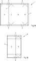
- Fig. 1A shows a known from the prior art blank 1, from which a packing jacket can be formed.
- the blank 1 may comprise a plurality of layers of different materials, for example paper, cardboard, plastic or metal, in particular aluminum.
- the blank 1 has a plurality of fold lines 2, which are intended to facilitate the folding of the blank 1 and divide the blank 1 into several areas.
- the blank 1 may be divided into a first side surface 3, a second side surface 4, a front surface 5, a rear surface 6, a sealing surface 7, bottom surfaces 8 and gable surfaces 9. From the blank 1, a packing jacket are formed by the blank 1 is folded such that the sealing surface 7 connected to the front surface 5, in particular welded 5 can be.
- Fig. 1B shows a known from the prior art packing jacket 10 in the flat folded state.
- the packing jacket 10 is made of the in Fig. 1A formed blank 1 formed.
- the blank 1 has been folded such that the sealing surface 7 and the front surface 5 are arranged overlapping, so that the two surfaces can be welded together flat.
- the result is a longitudinal seam 11.
- the packing jacket 10 is shown in a flat folded state. In this state, a side surface 4 (in Fig. 1B hidden) under the front surface 5 while the other side surface 3 on the rear surface 6 (in Fig. 1B covered).
- a plurality of packing shells 10 can be stacked particularly space-saving. Therefore, the packing shells 10 are frequently stacked at the place of manufacture and transported in stacks to the place of filling. Only there, the packaging coats 10 are stacked and unfolded to be filled with content, such as food.
- Fig. 1C is the packing jacket 10 made Fig. 1B shown in the unfolded state. Again, those are already related Fig. 1A or Fig. 1B described regions of the packing jacket 10 provided with corresponding reference numerals.
- the unfolded state is understood to mean a configuration in which an angle of approximately 90 ° forms between the two respectively adjacent surfaces 3, 4, 5, 6, so that the packing jacket 10 has a square or rectangular shape, depending on the shape of these surfaces Cross section has. Accordingly, the opposite side surfaces 3, 4 are arranged parallel to each other. The same applies to the front surface 5 and the rear surface 6.
- Fig. 1D shows the packing jacket 10 from Fig. 1C in the pre-folded state, ie in a state in which the fold lines 2 have been prefolded both in the region of the bottom surfaces 8 and in the region of the gable surfaces 9.
- Those areas of the bottom surfaces 8 and the gable surfaces 9, which adjoin the front surface 5 and the rear surface 6, are also referred to as rectangular surfaces 12.
- the rectangular surfaces 12 are folded inwards during the pre-folding and later form the bottom or the gable of the packaging.
- Those areas of the bottom surfaces 8 and the gable surfaces 9, which adjoin the side surfaces 3, 4, however, are referred to as triangular surfaces 13.
- the triangular surfaces 13 are folded outwardly during the pre-folding and form protruding areas of excess material, which are also referred to as "ears" 14 and are applied to the packaging in a later manufacturing step, for example by adhesive bonding.
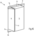
- Fig. 1E is the packing jacket 10 made Fig. 1D after welding, so shown in the filled and closed state.
- a fin seam 15 is produced after closing Fig. 1E stand the ears 14 and the fin seam 15 from. Both the ears 14 and the fin seam 15 are applied in a later manufacturing step, such as by adhesive bonding.
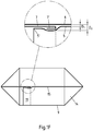
- Fig. 1F shows the packing jacket 10 from Fig. 1E in a top view.
- Fig. 1F In the illustrated perspective, it can be seen that the fin seam 15 of the packing jacket 10 in the region of the longitudinal seam 11 has a thickness D 2 which is greater than the thickness D 1 in the remaining region of the fin seam 15 This is because the end region 5 'of the front surface 5 and the end region 7' of the sealing surface 7 form an overlap in the region of the longitudinal seam 11. In the region of the longitudinal seam 11, the fin seam 15 thus has an at least three-layered instead of a two-layered construction.
- the thickness D 1 of the fin seam 15 is for example in the range between 0.8 mm and 1.0 mm, while the increased thickness D 2 of the fin seam 15 is for example in the range between 1.2 mm and 1.5 mm.
- the transition between the different ones Thickness is also called a "layer jump".
- one or both end regions 5 ', 7' can be folded over.
- a refolding of the inner end region has the advantage that only the innermost layer of the material of the blank 1 can come into contact with the contents of the package. This has the consequence that other layers of the material of the blank 1, for example a middle layer of cardboard, are separated from the contents of the packaging.
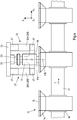
- Fig.2 shows a device 16 according to the invention for ultrasonic welding of packing coats 10 in a plan view. Shown is also a conveyor belt 17 with cells 18, in which the packing shells 10 are first led to the device 16 and are transported further after welding. The transport direction T of the packing shells 10 therefore runs parallel to the conveyor belt 17.
- the device 16 comprises two tools 19 for ultrasonic welding of the packing shells 10, wherein in the in Fig. 2 illustrated and so far preferred device 16 which is a tool a sonotrode 20 and the other tool an anvil 21. However, other - in Fig. 2 not shown - tools 19 are used.
- the sonotrode 20 has an effective area 20A with a round cross-sectional area and the anvil 21 has a round effective area 21A with a likewise round cross-sectional area.
- the sonotrode 20 and the anvil 21 are mounted such that between the effective areas 20A, 21A, a gap S is formed, the longitudinal direction X S of the transport direction T of the packing shells 10 corresponds.
- the gap S also has a High direction Y S and a transverse direction Z S , which are perpendicular to each other and perpendicular to the longitudinal direction X S of the gap S (see coordinate system in Fig. 2 ).
- the sonotrode 20 is rotatably mounted about a rotation axis 20B and the anvil 21 is rotatably supported about a rotation axis 21B.
- the two axes of rotation 20B, 21B are arranged parallel to one another and extend in the vertical direction Y S of the gap S (ie "vertical").
- the sonotrode 20 has an internal (and therefore in Fig. 2 not visible) drive, while the anvil 21 has an external drive 22 which drives the anvil 21 via a belt 23.
- the packing shells 10 are guided with their protruding fin seam 15 in the transport direction T through the gap S, wherein the active areas 20A, 21A touch the regions of the packing shells 10 to be welded (here: the fin seam 15) and weld them together.
- the anvil 21 is mounted on a base plate 24 such that the size of the gap S in the transverse direction Zs is variable.
- the storage of the anvil 21 takes place at the in Fig. 2 exemplified device 16 by two parallel springs 25, each comprising two mutually parallel leaf springs 26A, 26B.
- the leaf springs 26A, 26B of the two parallel springs 25 extend in the vertical direction and are each separated by two spacer elements 27 from each other.
- the two parallel springs 25 are connected to each other via a bridge 28 to which the anvil 21 is attached. Due to the spring-mounted mounting of the anvil 21, the anvil 21 can spring down (enlargement of the gap S) or spring in (reduction of the gap S), so that the effective region 21A of the anvil 21 with as constant a contact force as possible on the fin seam 15 acts.
- Fig. 3 the device 16 is off Fig. 2 in a side view along the section plane III-III Fig. 2 shown. For those areas of the device 16 that are already associated with Fig. 2 are described in Fig. 3 corresponding reference numerals used.
- the side view is the storage of the Anvil 21 on the two vertically extending parallel springs 25 particularly clearly visible.
- the leaf springs 26A, 26B of the parallel spring 25 extend in the vertical direction Ys of the gap S and thus in the vertical direction.
- the parallel spring 25 is fixed with its upper end to the base plate 24, while the lower end of the parallel spring 25 is a free end.
- the leaf springs 26A, 26B of the parallel spring 25 could also extend in the longitudinal direction X S of the gap S and thus in the horizontal direction. Due to the parallel course of the leaf springs 26A, 26B, the anvil 21 is displaced in parallel during compression and rebounding in the transverse direction Z S of the gap S, without being tilted. The axis of rotation 21B of the anvil 21 should therefore extend vertically in any position of the anvil 21 in the vertical direction Y S of the gap S and thus.
- Fig. 4 shows the device 16 from Fig. 2 in a front view along the section plane IV-IV Fig. 3 , For those areas of the device 16 that are already associated with Fig. 2 or Fig. 3 are described in Fig. 4 corresponding reference numerals used. For reasons of clarity, the section plane IV-IV has been selected such that the sonotrode 20 in FIG Fig. 4 is not visible.
- the anvil 21 is mounted centrally on the bridge 28 between both vertically extending parallel springs 25.
- connecting elements 29, for example screws can be provided. By the bridge 28, the forces in compression and rebound of the anvil 21 are transmitted evenly to both parallel springs 25.
Landscapes
- Engineering & Computer Science (AREA)
- Mechanical Engineering (AREA)
- Package Closures (AREA)
- Lining Or Joining Of Plastics Or The Like (AREA)
Priority Applications (1)
| Application Number | Priority Date | Filing Date | Title |
|---|---|---|---|
| PL16729833T PL3313645T3 (pl) | 2015-06-29 | 2016-06-07 | Urządzenie do obróbki rękawów opakowaniowych, w szczególności do zgrzewania ultradźwiękowego, oraz zastosowanie urządzenia |
Applications Claiming Priority (2)
| Application Number | Priority Date | Filing Date | Title |
|---|---|---|---|
| DE102015110387.7A DE102015110387A1 (de) | 2015-06-29 | 2015-06-29 | Vorrichtung zur Bearbeitung, insbesondere zur Ultraschallverschweißung, von Packungsmänteln |
| PCT/EP2016/062832 WO2017001153A1 (de) | 2015-06-29 | 2016-06-07 | Vorrichtung zur bearbeitung, insbesondere zur ultraschallverschweissung, von packungsmänteln sowie verwendung der vorrichtung |
Publications (2)
| Publication Number | Publication Date |
|---|---|
| EP3313645A1 EP3313645A1 (de) | 2018-05-02 |
| EP3313645B1 true EP3313645B1 (de) | 2019-10-02 |
Family
ID=56134320
Family Applications (1)
| Application Number | Title | Priority Date | Filing Date |
|---|---|---|---|
| EP16729833.0A Active EP3313645B1 (de) | 2015-06-29 | 2016-06-07 | Vorrichtung zur bearbeitung, insbesondere zur ultraschallverschweissung, von packungsmänteln sowie verwendung der vorrichtung |
Country Status (7)
| Country | Link |
|---|---|
| US (1) | US10625893B2 (pl) |
| EP (1) | EP3313645B1 (pl) |
| CN (1) | CN107708975A (pl) |
| DE (1) | DE102015110387A1 (pl) |
| ES (1) | ES2751575T3 (pl) |
| PL (1) | PL3313645T3 (pl) |
| WO (1) | WO2017001153A1 (pl) |
Families Citing this family (6)
| Publication number | Priority date | Publication date | Assignee | Title |
|---|---|---|---|---|
| CA2827863C (en) | 2011-02-24 | 2019-07-23 | Cmd Corporation | Method and apparatus for making bag using ultrasonic sealing |
| DE102017131262A1 (de) * | 2017-12-22 | 2019-07-11 | Sig Technology Ag | Gebinde aus Packungsmänteln und einer Umverpackung |
| IT201800003324A1 (it) | 2018-03-07 | 2019-09-07 | Gima Tt S P A | Procedimento per realizzare incarti ermetici e relativa macchina. |
| CN109733655B (zh) * | 2019-02-22 | 2023-10-03 | 东莞士格电子集团有限公司 | 一种圆柱形铝壳封口装置 |
| DE102019110620A1 (de) * | 2019-04-24 | 2020-10-29 | Sig Technology Ag | System zum Verpacken mehrerer Gebinde auf einer Platte |
| DE102023136343A1 (de) | 2023-12-21 | 2025-06-26 | Herrmann Ultraschalltechnik Gmbh & Co. Kg | Verfahren und Vorrichtung zum Verschweißen eines vereinzelten, mehrlagigen Produkts |
Family Cites Families (12)
| Publication number | Priority date | Publication date | Assignee | Title |
|---|---|---|---|---|
| US3272682A (en) * | 1962-08-13 | 1966-09-13 | Cavitron Ultrasonics Inc | Apparatus for joining thermoplastic sheet material with ultrasonic rotary vibrators |
| US3294616A (en) * | 1963-10-03 | 1966-12-27 | Branson Instr | Apparatus for sealing polymeric sheet material by ultrasonic energy |
| US3863826A (en) * | 1973-04-23 | 1975-02-04 | Branson Instr | Sonic or ultrasonic apparatus |
| US6547903B1 (en) | 2001-12-18 | 2003-04-15 | Kimberly-Clark Worldwide, Inc. | Rotary ultrasonic bonder or processor capable of high speed intermittent processing |
| DE10231742B3 (de) | 2002-07-13 | 2004-01-22 | Eduard Küsters Maschinenfabrik GmbH & Co. KG | Vorrichtung zum Bearbeiten einer Materialbahn, Verfahren zum Steuern und Ermitteln der Lage und/oder der Anpresskraft einer Sonotrode sowie Verfahren zur Überwachung der in einem Bearbeitungsspalt bewegten Materialbahn |
| DE10331064B4 (de) * | 2003-07-09 | 2007-10-04 | Eduard Küsters Maschinenfabrik GmbH & Co. KG | Vorrichtung zum Bearbeiten einer Materialbahn |
| WO2006074116A1 (en) * | 2005-01-03 | 2006-07-13 | 3M Innovative Properties Company | An elastic laminate material, and method of making |
| US7690548B2 (en) | 2005-01-03 | 2010-04-06 | 3M Innovative Properties Company | Apparatus of adjusting the position of an ultrasonic welding horn |
| DK2073942T3 (en) | 2006-09-28 | 2018-02-26 | 3L Ludvigsen As | Rotatable Ultrasonic Sealing Device |
| ITBO20060778A1 (it) * | 2006-11-15 | 2008-05-16 | Azionaria Costruzioni Acma Spa | Unita', di saldatura longitudinale ad ultrasuoni per la formazione di nastri tubolari continui |
| DE102009002295A1 (de) | 2009-04-09 | 2010-10-14 | Robert Bosch Gmbh | Vorrichtung zum Bearbeiten eines Packstoffs mittels Ultraschall |
| DE102013100474A1 (de) | 2013-01-17 | 2014-07-17 | Herrmann Ultraschalltechnik Gmbh & Co. Kg | Ultraschallschweißvorrichtung mit schwingungsentkoppeltem Gegenwerkzeug |
-
2015
- 2015-06-29 DE DE102015110387.7A patent/DE102015110387A1/de not_active Withdrawn
-
2016
- 2016-06-07 CN CN201680039073.9A patent/CN107708975A/zh active Pending
- 2016-06-07 WO PCT/EP2016/062832 patent/WO2017001153A1/de not_active Ceased
- 2016-06-07 PL PL16729833T patent/PL3313645T3/pl unknown
- 2016-06-07 US US15/739,860 patent/US10625893B2/en not_active Expired - Fee Related
- 2016-06-07 EP EP16729833.0A patent/EP3313645B1/de active Active
- 2016-06-07 ES ES16729833T patent/ES2751575T3/es active Active
Non-Patent Citations (1)
| Title |
|---|
| None * |
Also Published As
| Publication number | Publication date |
|---|---|
| US20180362201A1 (en) | 2018-12-20 |
| PL3313645T3 (pl) | 2020-01-31 |
| US10625893B2 (en) | 2020-04-21 |
| ES2751575T3 (es) | 2020-04-01 |
| EP3313645A1 (de) | 2018-05-02 |
| CN107708975A (zh) | 2018-02-16 |
| WO2017001153A1 (de) | 2017-01-05 |
| DE102015110387A1 (de) | 2016-12-29 |
Similar Documents
| Publication | Publication Date | Title |
|---|---|---|
| EP3313645B1 (de) | Vorrichtung zur bearbeitung, insbesondere zur ultraschallverschweissung, von packungsmänteln sowie verwendung der vorrichtung | |
| EP3439974B1 (de) | Vorrichtung zum formen von geschlossenen verpackungen | |
| DE60014619T2 (de) | Versiegelte Packung für fließfähige Nahrungsmittel und Verfahren zu ihrer Herstellung | |
| DE2935304C2 (de) | Laminiertes Verpackungsmaterial mit Faltlinien und Verfahren zu seiner Herstellung | |
| DE102013107429B3 (de) | Vorrichtung und Verfahren zum flüssigkeitsdichten Versiegeln von zwei sich teilweise überlappenden Verpackungsteilen und damit/danach hergestellter Behälter | |
| WO2015124396A1 (de) | Vorrichtung und verfahren zur vorfaltung von packungsmänteln | |
| EP0249180B2 (de) | Giebelpackung | |
| DE69310019T2 (de) | Heisssiegelvorrichtung | |
| EP3049333B1 (de) | Vorrichtung zum herstellen einer verbundverpackung | |
| DE4131465C2 (de) | Vorrichtung zum Ultraschallschweißen von Siegelnähten | |
| EP3672784B1 (de) | Schweissverfahren für einen mehrschichtigen verbund mit barriereschicht | |
| EP2909087A1 (de) | Verfahren zur herstellung von verpackungseinheiten in einer schlauchbeutelmaschine | |
| DE102011006930B4 (de) | Schweißvorrichtung | |
| DE102020121953A1 (de) | Vorrichtung zum Formen der Giebelflächen von Verpackungen | |
| EP4380784B1 (de) | Vorrichtung zum ultraschallverschweissen von verbundmaterial | |
| DE102006045338A1 (de) | Vorrichtung zum Versiegeln von mindestens zwei Lagen eines aufeinander gefalteten Giebels einer eine Längsnaht aufweisenden Mehrschichtverbundpackung und eine damit gebildete Mehrschichtverbundpackung | |
| DE102010039089B4 (de) | Schweißvorrichtung | |
| DE102009009200A1 (de) | Verpackungspalette mit Folienumhüllung | |
| EP3055121A1 (de) | Vorrichtung und verfahren zum flüssigkeitsdichten versiegeln von zwei sich teilweise überlappenden verpackungsteilen | |
| DE68912526T2 (de) | Verpackungseinlage sowie Zuschneidemaschine und Verwendungsverfahren für eine solche Einlage. | |
| WO2023135280A1 (de) | Schweissnaht, verfahren und vorrichtung zum verbinden von kunststofffolien durch thermisches fügen sowie verwendung einer schlagpresse | |
| DE3719038A1 (de) | Giebelpackung | |
| EP3976480A1 (de) | Vorrichtung und verfahren zum nachformen der giebelflächen von verpackungen mit schrägem giebel | |
| EP1852355A1 (de) | Verfahren und Querschweisseinrichtung zum Verpacken von mehreren Gegenständen in einer Kombinationsverpackung |
Legal Events
| Date | Code | Title | Description |
|---|---|---|---|
| STAA | Information on the status of an ep patent application or granted ep patent |
Free format text: STATUS: THE INTERNATIONAL PUBLICATION HAS BEEN MADE |
|
| PUAI | Public reference made under article 153(3) epc to a published international application that has entered the european phase |
Free format text: ORIGINAL CODE: 0009012 |
|
| STAA | Information on the status of an ep patent application or granted ep patent |
Free format text: STATUS: REQUEST FOR EXAMINATION WAS MADE |
|
| 17P | Request for examination filed |
Effective date: 20171122 |
|
| AK | Designated contracting states |
Kind code of ref document: A1 Designated state(s): AL AT BE BG CH CY CZ DE DK EE ES FI FR GB GR HR HU IE IS IT LI LT LU LV MC MK MT NL NO PL PT RO RS SE SI SK SM TR |
|
| AX | Request for extension of the european patent |
Extension state: BA ME |
|
| DAV | Request for validation of the european patent (deleted) | ||
| DAX | Request for extension of the european patent (deleted) | ||
| GRAP | Despatch of communication of intention to grant a patent |
Free format text: ORIGINAL CODE: EPIDOSNIGR1 |
|
| STAA | Information on the status of an ep patent application or granted ep patent |
Free format text: STATUS: GRANT OF PATENT IS INTENDED |
|
| INTG | Intention to grant announced |
Effective date: 20190619 |
|
| GRAS | Grant fee paid |
Free format text: ORIGINAL CODE: EPIDOSNIGR3 |
|
| GRAA | (expected) grant |
Free format text: ORIGINAL CODE: 0009210 |
|
| STAA | Information on the status of an ep patent application or granted ep patent |
Free format text: STATUS: THE PATENT HAS BEEN GRANTED |
|
| AK | Designated contracting states |
Kind code of ref document: B1 Designated state(s): AL AT BE BG CH CY CZ DE DK EE ES FI FR GB GR HR HU IE IS IT LI LT LU LV MC MK MT NL NO PL PT RO RS SE SI SK SM TR |
|
| REG | Reference to a national code |
Ref country code: GB Ref legal event code: FG4D Free format text: NOT ENGLISH |
|
| REG | Reference to a national code |
Ref country code: CH Ref legal event code: EP Ref country code: AT Ref legal event code: REF Ref document number: 1185710 Country of ref document: AT Kind code of ref document: T Effective date: 20191015 |
|
| REG | Reference to a national code |
Ref country code: DE Ref legal event code: R096 Ref document number: 502016006904 Country of ref document: DE |
|
| REG | Reference to a national code |
Ref country code: IE Ref legal event code: FG4D Free format text: LANGUAGE OF EP DOCUMENT: GERMAN |
|
| REG | Reference to a national code |
Ref country code: NL Ref legal event code: MP Effective date: 20191002 |
|
| REG | Reference to a national code |
Ref country code: LT Ref legal event code: MG4D |
|
| REG | Reference to a national code |
Ref country code: ES Ref legal event code: FG2A Ref document number: 2751575 Country of ref document: ES Kind code of ref document: T3 Effective date: 20200401 |
|
| PG25 | Lapsed in a contracting state [announced via postgrant information from national office to epo] |
Ref country code: NO Free format text: LAPSE BECAUSE OF FAILURE TO SUBMIT A TRANSLATION OF THE DESCRIPTION OR TO PAY THE FEE WITHIN THE PRESCRIBED TIME-LIMIT Effective date: 20200102 Ref country code: LT Free format text: LAPSE BECAUSE OF FAILURE TO SUBMIT A TRANSLATION OF THE DESCRIPTION OR TO PAY THE FEE WITHIN THE PRESCRIBED TIME-LIMIT Effective date: 20191002 Ref country code: NL Free format text: LAPSE BECAUSE OF FAILURE TO SUBMIT A TRANSLATION OF THE DESCRIPTION OR TO PAY THE FEE WITHIN THE PRESCRIBED TIME-LIMIT Effective date: 20191002 Ref country code: BG Free format text: LAPSE BECAUSE OF FAILURE TO SUBMIT A TRANSLATION OF THE DESCRIPTION OR TO PAY THE FEE WITHIN THE PRESCRIBED TIME-LIMIT Effective date: 20200102 Ref country code: SE Free format text: LAPSE BECAUSE OF FAILURE TO SUBMIT A TRANSLATION OF THE DESCRIPTION OR TO PAY THE FEE WITHIN THE PRESCRIBED TIME-LIMIT Effective date: 20191002 Ref country code: PT Free format text: LAPSE BECAUSE OF FAILURE TO SUBMIT A TRANSLATION OF THE DESCRIPTION OR TO PAY THE FEE WITHIN THE PRESCRIBED TIME-LIMIT Effective date: 20200203 Ref country code: FI Free format text: LAPSE BECAUSE OF FAILURE TO SUBMIT A TRANSLATION OF THE DESCRIPTION OR TO PAY THE FEE WITHIN THE PRESCRIBED TIME-LIMIT Effective date: 20191002 Ref country code: LV Free format text: LAPSE BECAUSE OF FAILURE TO SUBMIT A TRANSLATION OF THE DESCRIPTION OR TO PAY THE FEE WITHIN THE PRESCRIBED TIME-LIMIT Effective date: 20191002 Ref country code: GR Free format text: LAPSE BECAUSE OF FAILURE TO SUBMIT A TRANSLATION OF THE DESCRIPTION OR TO PAY THE FEE WITHIN THE PRESCRIBED TIME-LIMIT Effective date: 20200103 |
|
| PG25 | Lapsed in a contracting state [announced via postgrant information from national office to epo] |
Ref country code: IS Free format text: LAPSE BECAUSE OF FAILURE TO SUBMIT A TRANSLATION OF THE DESCRIPTION OR TO PAY THE FEE WITHIN THE PRESCRIBED TIME-LIMIT Effective date: 20200224 Ref country code: HR Free format text: LAPSE BECAUSE OF FAILURE TO SUBMIT A TRANSLATION OF THE DESCRIPTION OR TO PAY THE FEE WITHIN THE PRESCRIBED TIME-LIMIT Effective date: 20191002 Ref country code: CZ Free format text: LAPSE BECAUSE OF FAILURE TO SUBMIT A TRANSLATION OF THE DESCRIPTION OR TO PAY THE FEE WITHIN THE PRESCRIBED TIME-LIMIT Effective date: 20191002 Ref country code: RS Free format text: LAPSE BECAUSE OF FAILURE TO SUBMIT A TRANSLATION OF THE DESCRIPTION OR TO PAY THE FEE WITHIN THE PRESCRIBED TIME-LIMIT Effective date: 20191002 |
|
| PG25 | Lapsed in a contracting state [announced via postgrant information from national office to epo] |
Ref country code: AL Free format text: LAPSE BECAUSE OF FAILURE TO SUBMIT A TRANSLATION OF THE DESCRIPTION OR TO PAY THE FEE WITHIN THE PRESCRIBED TIME-LIMIT Effective date: 20191002 |
|
| REG | Reference to a national code |
Ref country code: DE Ref legal event code: R097 Ref document number: 502016006904 Country of ref document: DE |
|
| PG2D | Information on lapse in contracting state deleted |
Ref country code: IS |
|
| PG25 | Lapsed in a contracting state [announced via postgrant information from national office to epo] |
Ref country code: RO Free format text: LAPSE BECAUSE OF FAILURE TO SUBMIT A TRANSLATION OF THE DESCRIPTION OR TO PAY THE FEE WITHIN THE PRESCRIBED TIME-LIMIT Effective date: 20191002 Ref country code: EE Free format text: LAPSE BECAUSE OF FAILURE TO SUBMIT A TRANSLATION OF THE DESCRIPTION OR TO PAY THE FEE WITHIN THE PRESCRIBED TIME-LIMIT Effective date: 20191002 Ref country code: DK Free format text: LAPSE BECAUSE OF FAILURE TO SUBMIT A TRANSLATION OF THE DESCRIPTION OR TO PAY THE FEE WITHIN THE PRESCRIBED TIME-LIMIT Effective date: 20191002 Ref country code: IS Free format text: LAPSE BECAUSE OF FAILURE TO SUBMIT A TRANSLATION OF THE DESCRIPTION OR TO PAY THE FEE WITHIN THE PRESCRIBED TIME-LIMIT Effective date: 20200202 |
|
| PLBE | No opposition filed within time limit |
Free format text: ORIGINAL CODE: 0009261 |
|
| STAA | Information on the status of an ep patent application or granted ep patent |
Free format text: STATUS: NO OPPOSITION FILED WITHIN TIME LIMIT |
|
| PG25 | Lapsed in a contracting state [announced via postgrant information from national office to epo] |
Ref country code: SM Free format text: LAPSE BECAUSE OF FAILURE TO SUBMIT A TRANSLATION OF THE DESCRIPTION OR TO PAY THE FEE WITHIN THE PRESCRIBED TIME-LIMIT Effective date: 20191002 Ref country code: SK Free format text: LAPSE BECAUSE OF FAILURE TO SUBMIT A TRANSLATION OF THE DESCRIPTION OR TO PAY THE FEE WITHIN THE PRESCRIBED TIME-LIMIT Effective date: 20191002 |
|
| 26N | No opposition filed |
Effective date: 20200703 |
|
| PG25 | Lapsed in a contracting state [announced via postgrant information from national office to epo] |
Ref country code: SI Free format text: LAPSE BECAUSE OF FAILURE TO SUBMIT A TRANSLATION OF THE DESCRIPTION OR TO PAY THE FEE WITHIN THE PRESCRIBED TIME-LIMIT Effective date: 20191002 |
|
| PG25 | Lapsed in a contracting state [announced via postgrant information from national office to epo] |
Ref country code: MC Free format text: LAPSE BECAUSE OF FAILURE TO SUBMIT A TRANSLATION OF THE DESCRIPTION OR TO PAY THE FEE WITHIN THE PRESCRIBED TIME-LIMIT Effective date: 20191002 |
|
| REG | Reference to a national code |
Ref country code: CH Ref legal event code: PL |
|
| PG25 | Lapsed in a contracting state [announced via postgrant information from national office to epo] |
Ref country code: LU Free format text: LAPSE BECAUSE OF NON-PAYMENT OF DUE FEES Effective date: 20200607 |
|
| REG | Reference to a national code |
Ref country code: BE Ref legal event code: MM Effective date: 20200630 |
|
| PG25 | Lapsed in a contracting state [announced via postgrant information from national office to epo] |
Ref country code: IE Free format text: LAPSE BECAUSE OF NON-PAYMENT OF DUE FEES Effective date: 20200607 Ref country code: CH Free format text: LAPSE BECAUSE OF NON-PAYMENT OF DUE FEES Effective date: 20200630 Ref country code: LI Free format text: LAPSE BECAUSE OF NON-PAYMENT OF DUE FEES Effective date: 20200630 |
|
| PG25 | Lapsed in a contracting state [announced via postgrant information from national office to epo] |
Ref country code: BE Free format text: LAPSE BECAUSE OF NON-PAYMENT OF DUE FEES Effective date: 20200630 |
|
| PGFP | Annual fee paid to national office [announced via postgrant information from national office to epo] |
Ref country code: FR Payment date: 20210614 Year of fee payment: 6 Ref country code: DE Payment date: 20210614 Year of fee payment: 6 Ref country code: IT Payment date: 20210617 Year of fee payment: 6 |
|
| PGFP | Annual fee paid to national office [announced via postgrant information from national office to epo] |
Ref country code: GB Payment date: 20210615 Year of fee payment: 6 Ref country code: PL Payment date: 20210528 Year of fee payment: 6 Ref country code: TR Payment date: 20210429 Year of fee payment: 6 |
|
| PGFP | Annual fee paid to national office [announced via postgrant information from national office to epo] |
Ref country code: ES Payment date: 20210720 Year of fee payment: 6 |
|
| PG25 | Lapsed in a contracting state [announced via postgrant information from national office to epo] |
Ref country code: MT Free format text: LAPSE BECAUSE OF FAILURE TO SUBMIT A TRANSLATION OF THE DESCRIPTION OR TO PAY THE FEE WITHIN THE PRESCRIBED TIME-LIMIT Effective date: 20191002 Ref country code: CY Free format text: LAPSE BECAUSE OF FAILURE TO SUBMIT A TRANSLATION OF THE DESCRIPTION OR TO PAY THE FEE WITHIN THE PRESCRIBED TIME-LIMIT Effective date: 20191002 |
|
| PG25 | Lapsed in a contracting state [announced via postgrant information from national office to epo] |
Ref country code: MK Free format text: LAPSE BECAUSE OF FAILURE TO SUBMIT A TRANSLATION OF THE DESCRIPTION OR TO PAY THE FEE WITHIN THE PRESCRIBED TIME-LIMIT Effective date: 20191002 |
|
| REG | Reference to a national code |
Ref country code: AT Ref legal event code: MM01 Ref document number: 1185710 Country of ref document: AT Kind code of ref document: T Effective date: 20210607 |
|
| PG25 | Lapsed in a contracting state [announced via postgrant information from national office to epo] |
Ref country code: AT Free format text: LAPSE BECAUSE OF NON-PAYMENT OF DUE FEES Effective date: 20210607 |
|
| REG | Reference to a national code |
Ref country code: DE Ref legal event code: R119 Ref document number: 502016006904 Country of ref document: DE |
|
| GBPC | Gb: european patent ceased through non-payment of renewal fee |
Effective date: 20220607 |
|
| PG25 | Lapsed in a contracting state [announced via postgrant information from national office to epo] |
Ref country code: FR Free format text: LAPSE BECAUSE OF NON-PAYMENT OF DUE FEES Effective date: 20220630 |
|
| PG25 | Lapsed in a contracting state [announced via postgrant information from national office to epo] |
Ref country code: GB Free format text: LAPSE BECAUSE OF NON-PAYMENT OF DUE FEES Effective date: 20220607 Ref country code: DE Free format text: LAPSE BECAUSE OF NON-PAYMENT OF DUE FEES Effective date: 20230103 |
|
| REG | Reference to a national code |
Ref country code: ES Ref legal event code: FD2A Effective date: 20230727 |
|
| PG25 | Lapsed in a contracting state [announced via postgrant information from national office to epo] |
Ref country code: IT Free format text: LAPSE BECAUSE OF NON-PAYMENT OF DUE FEES Effective date: 20220607 |
|
| PG25 | Lapsed in a contracting state [announced via postgrant information from national office to epo] |
Ref country code: PL Free format text: LAPSE BECAUSE OF NON-PAYMENT OF DUE FEES Effective date: 20220607 |
|
| PG25 | Lapsed in a contracting state [announced via postgrant information from national office to epo] |
Ref country code: ES Free format text: LAPSE BECAUSE OF NON-PAYMENT OF DUE FEES Effective date: 20220608 |
|
| PG25 | Lapsed in a contracting state [announced via postgrant information from national office to epo] |
Ref country code: TR Free format text: LAPSE BECAUSE OF NON-PAYMENT OF DUE FEES Effective date: 20220607 |