EP3312523A1 - Gaswassererhitzer und sicherheitssteuerungsverfahren und -system dafür - Google Patents
Gaswassererhitzer und sicherheitssteuerungsverfahren und -system dafür Download PDFInfo
- Publication number
- EP3312523A1 EP3312523A1 EP16869368.7A EP16869368A EP3312523A1 EP 3312523 A1 EP3312523 A1 EP 3312523A1 EP 16869368 A EP16869368 A EP 16869368A EP 3312523 A1 EP3312523 A1 EP 3312523A1
- Authority
- EP
- European Patent Office
- Prior art keywords
- wind pressure
- set value
- output power
- water heater
- exhaust fan
- Prior art date
- Legal status (The legal status is an assumption and is not a legal conclusion. Google has not performed a legal analysis and makes no representation as to the accuracy of the status listed.)
- Granted
Links
- XLYOFNOQVPJJNP-UHFFFAOYSA-N water Substances O XLYOFNOQVPJJNP-UHFFFAOYSA-N 0.000 title claims abstract description 188
- 238000000034 method Methods 0.000 title claims abstract description 19
- 239000007789 gas Substances 0.000 claims abstract description 160
- 239000002912 waste gas Substances 0.000 claims abstract description 5
- 238000004891 communication Methods 0.000 claims description 4
- 238000002485 combustion reaction Methods 0.000 abstract description 13
- 238000010586 diagram Methods 0.000 description 5
- 230000003247 decreasing effect Effects 0.000 description 2
- 239000000463 material Substances 0.000 description 2
- 238000010792 warming Methods 0.000 description 2
- 238000005516 engineering process Methods 0.000 description 1
- 238000004880 explosion Methods 0.000 description 1
- 238000012986 modification Methods 0.000 description 1
- 230000004048 modification Effects 0.000 description 1
Images

Classifications
-
- F—MECHANICAL ENGINEERING; LIGHTING; HEATING; WEAPONS; BLASTING
- F24—HEATING; RANGES; VENTILATING
- F24H—FLUID HEATERS, e.g. WATER OR AIR HEATERS, HAVING HEAT-GENERATING MEANS, e.g. HEAT PUMPS, IN GENERAL
- F24H9/00—Details
- F24H9/20—Arrangement or mounting of control or safety devices
- F24H9/2007—Arrangement or mounting of control or safety devices for water heaters
- F24H9/2035—Arrangement or mounting of control or safety devices for water heaters using fluid fuel
-
- F—MECHANICAL ENGINEERING; LIGHTING; HEATING; WEAPONS; BLASTING
- F23—COMBUSTION APPARATUS; COMBUSTION PROCESSES
- F23N—REGULATING OR CONTROLLING COMBUSTION
- F23N3/00—Regulating air supply or draught
- F23N3/08—Regulating air supply or draught by power-assisted systems
- F23N3/082—Regulating air supply or draught by power-assisted systems using electronic means
-
- F—MECHANICAL ENGINEERING; LIGHTING; HEATING; WEAPONS; BLASTING
- F24—HEATING; RANGES; VENTILATING
- F24H—FLUID HEATERS, e.g. WATER OR AIR HEATERS, HAVING HEAT-GENERATING MEANS, e.g. HEAT PUMPS, IN GENERAL
- F24H15/00—Control of fluid heaters
- F24H15/10—Control of fluid heaters characterised by the purpose of the control
- F24H15/174—Supplying heated water with desired temperature or desired range of temperature
-
- F—MECHANICAL ENGINEERING; LIGHTING; HEATING; WEAPONS; BLASTING
- F24—HEATING; RANGES; VENTILATING
- F24H—FLUID HEATERS, e.g. WATER OR AIR HEATERS, HAVING HEAT-GENERATING MEANS, e.g. HEAT PUMPS, IN GENERAL
- F24H15/00—Control of fluid heaters
- F24H15/20—Control of fluid heaters characterised by control inputs
- F24H15/212—Temperature of the water
- F24H15/215—Temperature of the water before heating
-
- F—MECHANICAL ENGINEERING; LIGHTING; HEATING; WEAPONS; BLASTING
- F24—HEATING; RANGES; VENTILATING
- F24H—FLUID HEATERS, e.g. WATER OR AIR HEATERS, HAVING HEAT-GENERATING MEANS, e.g. HEAT PUMPS, IN GENERAL
- F24H15/00—Control of fluid heaters
- F24H15/20—Control of fluid heaters characterised by control inputs
- F24H15/212—Temperature of the water
- F24H15/219—Temperature of the water after heating
-
- F—MECHANICAL ENGINEERING; LIGHTING; HEATING; WEAPONS; BLASTING
- F24—HEATING; RANGES; VENTILATING
- F24H—FLUID HEATERS, e.g. WATER OR AIR HEATERS, HAVING HEAT-GENERATING MEANS, e.g. HEAT PUMPS, IN GENERAL
- F24H15/00—Control of fluid heaters
- F24H15/20—Control of fluid heaters characterised by control inputs
- F24H15/281—Input from user
-
- F—MECHANICAL ENGINEERING; LIGHTING; HEATING; WEAPONS; BLASTING
- F24—HEATING; RANGES; VENTILATING
- F24H—FLUID HEATERS, e.g. WATER OR AIR HEATERS, HAVING HEAT-GENERATING MEANS, e.g. HEAT PUMPS, IN GENERAL
- F24H15/00—Control of fluid heaters
- F24H15/30—Control of fluid heaters characterised by control outputs; characterised by the components to be controlled
- F24H15/305—Control of valves
- F24H15/31—Control of valves of valves having only one inlet port and one outlet port, e.g. flow rate regulating valves
-
- F—MECHANICAL ENGINEERING; LIGHTING; HEATING; WEAPONS; BLASTING
- F24—HEATING; RANGES; VENTILATING
- F24H—FLUID HEATERS, e.g. WATER OR AIR HEATERS, HAVING HEAT-GENERATING MEANS, e.g. HEAT PUMPS, IN GENERAL
- F24H15/00—Control of fluid heaters
- F24H15/30—Control of fluid heaters characterised by control outputs; characterised by the components to be controlled
- F24H15/345—Control of fans, e.g. on-off control
- F24H15/35—Control of the speed of fans
-
- F—MECHANICAL ENGINEERING; LIGHTING; HEATING; WEAPONS; BLASTING
- F24—HEATING; RANGES; VENTILATING
- F24H—FLUID HEATERS, e.g. WATER OR AIR HEATERS, HAVING HEAT-GENERATING MEANS, e.g. HEAT PUMPS, IN GENERAL
- F24H15/00—Control of fluid heaters
- F24H15/30—Control of fluid heaters characterised by control outputs; characterised by the components to be controlled
- F24H15/355—Control of heat-generating means in heaters
- F24H15/36—Control of heat-generating means in heaters of burners
Definitions
- the present disclosure relates to the water heater technology field, and more particular to, a gas water heater, a safety control method for a gas water heater, and a safety control system for a gas water heater.
- gas water heaters on the market typically include: D type (natural exhaust type) gas water heaters, Q type (forced exhaust type) gas water heaters, P type (natural exhaust and air supply type) gas water heaters, G type (forced exhaust and air supply type) gas water heaters and W type (outside set-up type) gas water heaters and so on.
- D type natural exhaust type
- Q type forced exhaust type
- P type natural exhaust and air supply type
- G type forced exhaust and air supply type gas water heaters
- W type outside set-up type gas water heaters and so on.
- Q type and G type gas water heaters are provided with exhaust fans directly, so as to forcedly exhaust waste gas generated when burning gas, such that the residual gas explosion or the like may be avoided.
- the Q type gas water heater mostly adopts a wind pressure detecting unit to detect the wind pressure at an air outlet and controls the exhaust fan and an igniter unit according to the detected wind pressure, so as to ensure that the gas water heater may work normally.
- the combustion operation of the gas water heater in the case of the wind flow backward may be avoided by adopting the wind pressure detecting unit, the device cost is high, and the operation of the gas water heater may be interrupted due to the slight wind pressure, resulting in that the user is unable to use the gas water heater normally.
- the present disclosure aims to solve at least one of the above technical problems in the related art to at least some extent.
- a first objective of the present disclosure aims to provide a safety control system for a gas water heater.
- the safety control system may ensure that the gas water heater can have a good combustion condition and operate safely and reliably. Also, the response speed of the system is fast and accurate air volume may be provided, such that the control accuracy is improved.
- a second objective of the present disclosure aims to provide a gas water heater.
- a third objective of the present disclosure aims to provide a safety control method for a gas water heater.
- a safety control system for a gas water heater including: an exhaust fan, configured to exhaust waste gas generated when the gas water heater burns gas; a rotational speed detecting unit, configured to detect a rotational speed of the exhaust fan; a power obtaining unit, configured to obtain a set value for output power of the exhaust fan; and an exhaust control unit, connected to the exhaust fan, the rotational speed detecting unit and the power obtaining unit respectively, and configured to determine a wind pressure situation at an air outlet of the exhaust fan according to the rotational speed and the set value for the output power, and to adjust the set value for the output power according to the wind pressure situation.
- the rotational speed detecting unit obtains the rotational speed of the exhaust fan
- the power obtaining unit obtains the set value for the output power of the exhaust fan
- the exhaust control unit determines the wind pressure situation at the air outlet of the exhaust fan according to the rotational speed and the set value for the output power and adjusts the set value for the output power according to the wind pressure situation, such that the adjustment of rotational speed of the exhaust fan may be realized, and it is guaranteed that a good combustion condition may be achieved after mixing the introduced gas and air during the operation of the gas water heater, thus ensuring that the gas water heater can operate safely and reliably.
- the direct adjustment of the set value for the output power is an active control, which not only has a fast response speed and but also provides more accurate air volume when compared to the passive control on the rotational speed of the exhaust fan, such that the control accuracy is improved and the whole system cost is low.
- the exhaust control unit is configured to determine a wind pressure situation at an air outlet of the exhaust fan according to the rotational speed and the set value for the output power and to adjust the set value for the output power according to the wind pressure situation by performing following acts: controlling the set value for the output power to be reduced by a first predetermined value when the exhaust control unit determines that the wind pressure situation is a low wind pressure situation; controlling the set value for the output power to keep unchanged when the exhaust control unit determines that the wind pressure situation is a medium wind pressure situation; and controlling the set value for the output power to be increased by a second predetermined value when the exhaust control unit determines that the wind pressure situation is a high wind pressure situation.
- the above safety control system further includes a system control unit configured to perform a mutual communication with the exhaust control unit, in which the exhaust control unit is configured to send a shut-off signal to the system control unit such that the system control unit controls the gas water heater to shut off according to the shut-off signal, when the exhaust control unit determines that the wind pressure situation is an extreme high wind pressure situation or the rotational speed is higher than a rotational speed threshold.
- the above safety control system further includes: a water supply unit, connected to the system control unit; and a temperature obtaining unit, connected with the system control unit, configured to obtain a set temperature for output water of the gas water heater and a cold water temperature of the gas water heater, in which the system control unit is configured to calculate a total heat required by the gas water heater according to a water supply quantity of the water supply unit, the set temperature for the output water and the cold water temperature, and to obtain a current control instruction and an initial set value for the output power according to the total heat.
- the above safety control system further includes a gas unit, connected to the system control unit and provided with a proportional valve, in which the system control unit is configured to control the gas unit by controlling the proportional valve according to the current control instruction.
- the gas water heater is a forced exhaust type gas water heater.
- embodiments of a second aspect of the present disclosure provide a gas water heater, including the above safety control system.
- the gas water heater may determine the wind pressure situation at the air outlet of the exhaust fan according to the rotational speed and the set value for the output power and adjust the set value for the output power according to the wind pressure situation, such that the adjustment of rotational speed of the exhaust fan may be realized, and it is guaranteed that a good combustion condition may be achieved after mixing the introduced gas and air during the operation of the gas water heater, thus ensuring the safe and reliable operation of the gas water heater.
- the direct adjustment of the set value for the output power is an active control, which not only has a fast response speed but also provides more accurate air volume when compared to the passive control on the rotational speed of the exhaust fan, such that the control accuracy is improved.
- embodiments of a third aspect of the present disclosure provide a safety control method for a gas water heater, including: detecting a rotational speed of an exhaust fan in the gas water heater; obtaining a set value for output power of the exhaust fan; and determining a wind pressure situation at an air outlet of the exhaust fan according to the rotational speed and the set value for the output power, and adjusting the set value for the output power according to the wind pressure situation.
- the safety control method for a gas water heater firstly the rotational speed of the exhaust fan is detected and the set value for the output power of the exhaust fan is obtained, and then the wind pressure situation at the air outlet of the exhaust fan is determined according to the rotational speed and the set value for the output power and the set value for the output power is adjusted according to the wind pressure situation, such that the adjustment of rotational speed of the exhaust fan may be realized, and it is guaranteed that a good combustion condition may be achieved after mixing the introduced gas and air during the operation of the gas water heater, thus ensuring a safe and reliable operation of the gas water heater.
- the direct adjustment of the set value for the output power is an active control, which not only has a fast response speed but also provides more accurate air volume when compared to the passive control on the rotational speed of the exhaust fan, such that the control accuracy is improved.
- determining a wind pressure situation at an air outlet of the exhaust fan according to the rotational speed and the set value for the output power and adjusting the set value for the output power according to the wind pressure situation includes: controlling the set value for the output power to be reduced by a first predetermined value when it is determined that the wind pressure situation is a low wind pressure situation; controlling the set value for the output power to keep unchanged when it is determined that the wind pressure situation is a medium wind pressure situation; and controlling the set value for the output power to be increased by a second predetermined value when it is determined that the wind pressure situation is a high wind pressure situation.
- determining a wind pressure situation at an air outlet of the exhaust fan according to the rotational speed and the set value for the output power and adjusting the set value for the output power according to the wind pressure situation further includes: controlling the gas water heater to shut off, when it is determined that the wind pressure situation is an extreme high wind pressure situation or the rotational speed is higher than a rotational speed threshold.
- the above safety control method further includes: obtaining a water supply quantity of the gas water heater, a set temperature for output water of the gas water heater and a cold water temperature of the gas water heater; calculating a total heat required by the gas water heater according to the water supply quantity, the set temperature for the output water and the cold water temperature, and obtaining a current control instruction and an initial set value for the output power according to the total heat; and performing a gas burning control by controlling a proportional valve in a gas unit of the gas water heater according to the current control instruction.
- Fig. 1 is a block diagram of a safety control system for a gas water heater according to an embodiment of the present disclosure.
- the safety control system for a gas water heater includes an exhaust fan 10, a rotational speed detecting unit 20, a power obtaining unit 30 and an exhaust control unit 40.
- the exhaust fan 10 is configured to exhaust waste gas generated when the gas water heater burns gas.
- the rotational speed detecting unit 20 is configured to detect a rotational speed of the exhaust fan 10.
- the power obtaining unit 30 is configured to obtain a set value for output power of the exhaust fan.
- the exhaust control unit 40 is connected to the exhaust fan 10, the rotational speed detecting unit 20 and the power obtaining unit 30 respectively.
- the exhaust control unit 40 is configured to determine a wind pressure situation at an air outlet of the exhaust fan 10 according to the rotational speed of the exhaust fan 10 and the set value for the output power of the exhaust fan 10, and to adjust the set value for the output power of the exhaust fan 10.
- the rotational speed of the exhaust fan 10 is detected by the rotational speed detecting unit 20 in real time and the wind pressure situation at the air outlet of the exhaust fan 10 is determined in combination with the set value for the output power of the exhaust fan 10, and then the set value for the output power of the exhaust fan 10 is adjusted according to the wind pressure situation, such that the adjustment of rotational speed of the exhaust fan 10 may be realized, and it is guaranteed that a good combustion condition may be achieved after mixing the introduced gas and air during the operation of the gas water heater, thus ensuring the safety and reliability of the gas water heater.
- the direct adjustment of the set value for the output power is an active control, which not only has a fast response speed but also provides more accurate air volume when compared to the passive control on the rotational speed of the exhaust fan, such that the control accuracy is improved and the whole system cost is low.
- the set value for the output power of the exhaust fan 10 is controlled to be reduced by a first predetermined value when the exhaust control unit 40 determines that the wind pressure situation of the exhaust fan 10 is a low wind pressure situation; the set value for the output power of the exhaust fan 10 is controlled to keep unchanged when the exhaust control unit 40 determines that the wind pressure situation of the exhaust fan 10 is a medium wind pressure situation; and the set value for the output power of the exhaust fan 10 is controlled to be increased by a second predetermined value when the exhaust control unit 40 determines that the wind pressure situation of the exhaust fan 10 is a high wind pressure situation.
- the first predetermined value and the second predetermined value may be determined according to actual situations, which may be fixed values or may be adjusted dynamically according to actual situations.
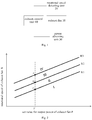
- the set value for output power of the exhaust fan 10 is PI
- the set value for output power of the exhaust fan 10 is adjusted to P1- ⁇ P1
- the rotational speed meets a condition of C ⁇ R ⁇ B
- the set value for output power of the exhaust fan 10 is kept unchanged
- the rotational speed meets a condition of B ⁇ R ⁇ A
- the set value for output power of the exhaust fan 10 is adjusted to P1+ ⁇ P2, such that the active control on the rotational speed of the exhaust fan is realized, and it is guaranteed that the air volume of the exhaust fan reaches an equilibrium with the wind pressure at the air outlet and the gas water heater would have a good combustion condition.
- the above safety control system for a gas water heater further includes a system control unit 50.
- the system control unit 50 is configured to perform a mutual communication with the exhaust control unit 40. If the exhaust control unit 40 determines the wind pressure situation at the air outlet is an extreme high wind pressure situation or the rotational speed of the exhaust fan 10 is higher than a rotational speed threshold, the exhaust control unit 40 sends a shut-off signal to the system control unit 50, such that the system control unit 50 controls the gas water heater to shut off according to the shut-off signal.
- the above safety control system for a gas water heater further includes a water supply unit 60 and a temperature obtaining unit (not shown).
- the water supply unit 60 is connected to the system control unit 50, and the temperature obtaining unit is also connected to the system control unit 50.
- the temperature obtaining unit is configured to obtain set temperature for output water of the gas water heater and a cold water temperature of the gas water heater.
- the system control unit 50 is configured to calculate a total heat required by the gas water heater according to a water supply quantity of the water supply unit 60, the set temperature for the output water and the cold water temperature, and to obtain a current control instruction and an initial set value for the output power of the exhaust fan 10 according to the total heat.
- the above safety control system for a gas water heater further includes a gas unit 70 connected to the system control unit 50 and provided with a proportional valve (not shown).
- the system control unit 50 is configured to control the gas unit 70 by controlling the proportional valve according to the current control instruction.
- the system control unit 50 firstly calculates the total heat required by the gas water heater for warming the cold water to the set temperature for output water according to the set temperature for output water set by the user, the water supply quantity of the water supply unit 60 and the cold water temperature. And then, as shown in Fig. 4 , the system control unit 50 obtains the control quantity (i.e., the current control instruction) of the proportional valve in the gas unit 70 and the set value for output power to be configured as an initial set value for output power according to the total heat required by the gas water heater. Finally, the system control unit 50 controls the proportional valve according to the obtained control quantity so as to control the gas unit 70, and sends the initial set value for output power to the exhaust control unit 40 via the CAN bus or the like.
- the control quantity i.e., the current control instruction
- the system control unit 50 obtains the control quantity of the proportional valve and the initial set value for output power again, and controls the gas water heater based on the above-mentioned procedure.
- the gas water heater may be a forced exhaust type gas water heater, which is not limited herein.
- the exhaust control unit determines the wind pressure situation at the air outlet of the exhaust fan according to the rotational speed and the set value for output power and adjusts the set value for the output power of the exhaust fan according to the wind pressure situation, such that the adjustment of rotational speed of the exhaust fan may be realized, and it is guaranteed that a good combustion condition may be achieved after mixing the introduced gas and air during the operation of the gas water heater, thus ensuring the safe and reliable operation of the gas water heater.
- the direct adjustment of the set value for the output power is an active control, which not only has a fast response speed but also provides more accurate air volume when compared to the passive control on the rotational speed of the exhaust fan, such that the control accuracy is improved and the whole system cost is low.
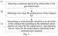
- Fig. 5 is a flow chart of a safety control method for a gas water heater according to an embodiment of the present disclosure. As shown in Fig. 5 , the safety control method includes following steps.
- step S1 a rotational speed of an exhaust fan in the gas water heater is detected.
- step S2 a set value for output power of the exhaust fan is obtained.
- step S3 a wind pressure situation at an air outlet of the exhaust fan is determined according to the rotational speed and the set value for output power, and the set value for output power is adjusted according to the wind pressure situation.
- the rotational speed of the exhaust fan is detected in real time, and the wind pressure situation at the air outlet of the exhaust fan is determined in combination with the set value for the output power of the exhaust fan, and then the set value for the output power of the exhaust fan is adjusted according to the wind pressure situation, such that the adjustment of rotational speed of the exhaust fan may be realized, and it is guaranteed that a good combustion condition may be achieved after mixing the introduced gas and air during the operation of the gas water heater, thus ensuring the safety and reliability of the gas water heater.
- the direct adjustment of the set value for the output power is an active control, which not only has a fast response speed but also provides more accurate air volume when compared to the passive control on the rotational speed of the exhaust fan, such that the control accuracy is improved.
- determining a wind pressure situation at an air outlet of the exhaust fan according to the rotational speed and the set value for the output power and adjusting the set value for the output power according to the wind pressure situation includes: controlling the set value for the output power to be reduced by a first predetermined value when it is determined that the wind pressure situation is a low wind pressure situation; controlling the set value for the output power to keep unchanged when it is determined that the wind pressure situation is a medium wind pressure situation; and controlling the set value for the output power to be increased by a second predetermined value when it is determined that the wind pressure situation is a high wind pressure situation.
- determining a wind pressure situation at an air outlet of the exhaust fan according to the rotational speed and the set value for the output power and adjusting the set value for the output power according to the wind pressure situation further includes: controlling the gas water heater to shut off, when it is determined that the wind pressure situation is an extreme high wind pressure situation or the rotational speed is higher than a rotational speed threshold.
- the above safety control method further includes: obtaining a water supply quantity of the gas water heater, a set temperature for output water of the gas water heater and a cold water temperature of the gas water heater; calculating a total heat required by the gas water heater according to the water supply quantity, the set temperature for the output water and the cold water temperature, and obtaining a current control instruction and an initial set value for the output power according to the total heat; and performing a gas burning control by controlling a proportional valve in a gas unit of the gas water heater according to the current control instruction.
- the control quantity i.e., the current control instruction
- the proportional valve in the gas unit and the set value for output power to be configured as an initial set value for output power are obtained according to the total heat required by the gas water heater.
- the proportional valve is controlled according to the obtained control quantity so as to control the gas unit, and the exhaust fan is controlled according to the initial set value for output power.
- the rotational speed of the exhaust fan is detected in real time, and is determined.
- the control quantity of the proportional valve and the initial set value for output power are obtained again, and the gas water heater is controlled based on the above-mentioned procedure.
- the safety control method for a gas water heater firstly the rotational speed of the exhaust fan is detected and the set value for the output power of the exhaust fan is obtained, and then the wind pressure situation at the air outlet of the exhaust fan is determined according to the rotational speed and the set value for the output power and the set value for the output power is adjusted according to the wind pressure situation, such that the adjustment of rotational speed of the exhaust fan may be realized, and it is guaranteed that a good combustion condition may be achieved after mixing the introduced gas and air during the operation of the gas water heater, thus ensuring a safe and reliable operation of the gas water heater.
- the direct adjustment of the set value for the output power is an active control, which not only has a fast response speed but also provides more accurate air volume when compared to the passive control on the rotational speed of the exhaust fan, such that the control accuracy is improved.
- a gas water heater according to embodiments of the present disclosure, which includes the above safety control system for a gas water heater.
- the gas water heater may determine the wind pressure situation at the air outlet of the exhaust fan according to the rotational speed and the set value for the output power and adjust the set value for the output power according to the wind pressure situation, such that the adjustment of rotational speed of the exhaust fan may be realized, and it is guaranteed that a good combustion condition may be achieved after mixing the introduced gas and air during the operation of the gas water heater, thus ensuring the safe and reliable operation of the gas water heater.
- the direct adjustment of the set value for the output power is an active control, which not only has a fast response speed but also provides more accurate air volume when compared to the passive control on the rotational speed of the exhaust fan, such that the control accuracy is improved.
- first and second are used herein for purposes of description and are not intended to indicate or imply relative importance or significance or to imply the number of indicated technical features.
- the feature defined with “first” and “second” may comprise one or more of this feature.
- a plurality of' means two or more than two, unless specified otherwise.
- the terms “mounted,” “connected,” “coupled,” “fixed” and the like are used broadly, and may be, for example, fixed connections, detachable connections, or integral connections; may also be mechanical or electrical connections; may also be direct connections or indirect connections via intervening structures; may also be inner communications of two elements, which can be understood by those skilled in the art according to specific situations.
- a structure in which a first feature is "on" or “below” a second feature may include an embodiment in which the first feature is in direct contact with the second feature, and may also include an embodiment in which the first feature and the second feature are not in direct contact with each other, but are contacted via an additional feature formed therebetween.
- a first feature "on,” “above,” or “on top of' a second feature may include an embodiment in which the first feature is right or obliquely “on,” “above,” or “on top of' the second feature, or just means that the first feature is at a height higher than that of the second feature; while a first feature "below,” “under,” or “on bottom of' a second feature may include an embodiment in which the first feature is right or obliquely “below,” “under,” or “on bottom of' the second feature, or just means that the first feature is at a height lower than that of the second feature.
Landscapes
- Engineering & Computer Science (AREA)
- Physics & Mathematics (AREA)
- Chemical & Material Sciences (AREA)
- Combustion & Propulsion (AREA)
- Mechanical Engineering (AREA)
- General Engineering & Computer Science (AREA)
- Thermal Sciences (AREA)
- Fluid Mechanics (AREA)
- Regulation And Control Of Combustion (AREA)
Applications Claiming Priority (2)
| Application Number | Priority Date | Filing Date | Title |
|---|---|---|---|
| CN201610792278.6A CN107781999A (zh) | 2016-08-31 | 2016-08-31 | 燃气热水器及其安全控制系统和方法 |
| PCT/CN2016/113301 WO2018040433A1 (zh) | 2016-08-31 | 2016-12-29 | 燃气热水器及其安全控制系统和方法 |
Publications (3)
| Publication Number | Publication Date |
|---|---|
| EP3312523A1 true EP3312523A1 (de) | 2018-04-25 |
| EP3312523A4 EP3312523A4 (de) | 2018-04-25 |
| EP3312523B1 EP3312523B1 (de) | 2019-09-25 |
Family
ID=59895020
Family Applications (1)
| Application Number | Title | Priority Date | Filing Date |
|---|---|---|---|
| EP16869368.7A Active EP3312523B1 (de) | 2016-08-31 | 2016-12-29 | Gaswassererhitzer und sicherheitssteuerungsverfahren und -system dafür |
Country Status (4)
| Country | Link |
|---|---|
| EP (1) | EP3312523B1 (de) |
| CN (1) | CN107781999A (de) |
| ES (1) | ES2763798T3 (de) |
| WO (1) | WO2018040433A1 (de) |
Families Citing this family (5)
| Publication number | Priority date | Publication date | Assignee | Title |
|---|---|---|---|---|
| CN109028594B (zh) * | 2018-06-01 | 2021-06-15 | 广东万和热能科技有限公司 | 燃气采暖热水炉空燃比控制方法、装置及燃气采暖热水炉 |
| CN110207387A (zh) * | 2018-09-04 | 2019-09-06 | 华帝股份有限公司 | 燃气热水器风压系统自适应的控制方法 |
| CN110207362B (zh) * | 2018-11-08 | 2021-08-06 | 华帝股份有限公司 | 一种燃气热水器风量自适应控制方法 |
| CN110779214B (zh) * | 2019-09-29 | 2021-04-27 | 华帝股份有限公司 | 一种燃气热水器的控制方法 |
| CN110953729B (zh) * | 2019-12-17 | 2021-09-17 | 华帝股份有限公司 | 一种燃气热水器的控制方法 |
Family Cites Families (11)
| Publication number | Priority date | Publication date | Assignee | Title |
|---|---|---|---|---|
| JPH09261988A (ja) * | 1996-03-26 | 1997-10-03 | Noritz Corp | 直流モータ制御装置 |
| JP3465518B2 (ja) * | 1997-01-31 | 2003-11-10 | 株式会社ノーリツ | ファンモータ制御装置 |
| JP4354374B2 (ja) * | 2004-09-21 | 2009-10-28 | リンナイ株式会社 | 燃焼装置 |
| KR20090093407A (ko) * | 2008-02-29 | 2009-09-02 | 린나이코리아 주식회사 | 보일러의 연소제어시 안전제어장치 및 그 방법 |
| CN101303161B (zh) * | 2008-06-12 | 2010-07-21 | 中山华帝燃具股份有限公司 | 智能化燃气热水器的控制方法 |
| US8498523B2 (en) * | 2009-02-03 | 2013-07-30 | Intellihot, Inc. | Apparatus and control method for a hybrid tankless water heater |
| CN102080878B (zh) * | 2009-11-27 | 2013-05-08 | 海尔集团公司 | 燃气设备的风机控制方法及装置 |
| CN201561578U (zh) * | 2009-12-08 | 2010-08-25 | 海尔集团公司 | 燃气设备的风机控制装置 |
| JP5718747B2 (ja) * | 2011-07-06 | 2015-05-13 | リンナイ株式会社 | 燃焼装置 |
| CN202813802U (zh) * | 2012-10-08 | 2013-03-20 | 樱花卫厨(中国)股份有限公司 | 燃气热水器用智能风压系统 |
| CN103727676B (zh) * | 2013-12-02 | 2017-01-18 | 芜湖美的厨卫电器制造有限公司 | 燃气热水器 |
-
2016
- 2016-08-31 CN CN201610792278.6A patent/CN107781999A/zh active Pending
- 2016-12-29 WO PCT/CN2016/113301 patent/WO2018040433A1/zh active Application Filing
- 2016-12-29 ES ES16869368T patent/ES2763798T3/es active Active
- 2016-12-29 EP EP16869368.7A patent/EP3312523B1/de active Active
Also Published As
| Publication number | Publication date |
|---|---|
| WO2018040433A1 (zh) | 2018-03-08 |
| CN107781999A (zh) | 2018-03-09 |
| ES2763798T3 (es) | 2020-06-01 |
| EP3312523A4 (de) | 2018-04-25 |
| EP3312523B1 (de) | 2019-09-25 |
Similar Documents
| Publication | Publication Date | Title |
|---|---|---|
| EP3312523A1 (de) | Gaswassererhitzer und sicherheitssteuerungsverfahren und -system dafür | |
| CN106225249B (zh) | 燃气热水器及其安全控制系统和方法 | |
| US10619864B2 (en) | Heat pump water heater and control method thereof | |
| CN107917534B (zh) | 一种水流量控制方法及燃气热水器 | |
| EP3309473B1 (de) | Gaswassererhitzer und sicherheitssteuerungsverfahren und -system dafür | |
| CN103868145B (zh) | 壁挂炉的防干烧控制方法 | |
| CN108474587B (zh) | 供暖热水兼用锅炉及其控制方法 | |
| US10775078B2 (en) | Gas water heater and safety control method and system therefor | |
| US10330344B2 (en) | Temperature algorithm for water heater | |
| KR101506548B1 (ko) | 보일러의 난방 제어 방법 및 제어 장치 | |
| KR101782941B1 (ko) | 음압식 온수 보일러의 구동 제어 장치 및 방법 | |
| CN109945503B (zh) | 燃气具的风量控制方法、装置、存储介质及燃气具 | |
| JP5902126B2 (ja) | 燃焼装置 | |
| JP2009030845A (ja) | 空調制御システム | |
| WO2018059231A1 (zh) | 风扇及其风速控制方法 | |
| JP5414648B2 (ja) | 複合燃焼装置 | |
| US20150198133A1 (en) | Engine coolant temperature regulation apparatus and method | |
| JP2014145534A (ja) | コンロ用バーナの火力制御装置 | |
| JP5648789B2 (ja) | ボイラ | |
| JP2010249133A (ja) | 補正メガワットバックアップ曲線法 | |
| JP2016057045A (ja) | 燃焼装置 | |
| KR20160132695A (ko) | 열유속을 높인 온수 난방 보일러 | |
| JP2006250498A (ja) | 燃焼装置 | |
| JP3960229B2 (ja) | 温水暖房装置 | |
| KR101969266B1 (ko) | 유체마찰 보일러 |
Legal Events
| Date | Code | Title | Description |
|---|---|---|---|
| STAA | Information on the status of an ep patent application or granted ep patent |
Free format text: STATUS: UNKNOWN |
|
| STAA | Information on the status of an ep patent application or granted ep patent |
Free format text: STATUS: THE INTERNATIONAL PUBLICATION HAS BEEN MADE |
|
| PUAI | Public reference made under article 153(3) epc to a published international application that has entered the european phase |
Free format text: ORIGINAL CODE: 0009012 |
|
| STAA | Information on the status of an ep patent application or granted ep patent |
Free format text: STATUS: REQUEST FOR EXAMINATION WAS MADE |
|
| 17P | Request for examination filed |
Effective date: 20170606 |
|
| A4 | Supplementary search report drawn up and despatched |
Effective date: 20171206 |
|
| AK | Designated contracting states |
Kind code of ref document: A1 Designated state(s): AL AT BE BG CH CY CZ DE DK EE ES FI FR GB GR HR HU IE IS IT LI LT LU LV MC MK MT NL NO PL PT RO RS SE SI SK SM TR |
|
| AX | Request for extension of the european patent |
Extension state: BA ME |
|
| RIN1 | Information on inventor provided before grant (corrected) |
Inventor name: XUE, CHENGZHI Inventor name: QIAN, XIAOLIN Inventor name: DAI, XIANFENG Inventor name: LIANG, GUORONG Inventor name: TANG, XIAOE |
|
| RIC1 | Information provided on ipc code assigned before grant |
Ipc: F23N 3/08 20060101ALI20190528BHEP Ipc: F04D 27/00 20060101ALI20190528BHEP Ipc: F24H 9/20 20060101AFI20190528BHEP |
|
| GRAP | Despatch of communication of intention to grant a patent |
Free format text: ORIGINAL CODE: EPIDOSNIGR1 |
|
| STAA | Information on the status of an ep patent application or granted ep patent |
Free format text: STATUS: GRANT OF PATENT IS INTENDED |
|
| DAV | Request for validation of the european patent (deleted) | ||
| DAX | Request for extension of the european patent (deleted) | ||
| INTG | Intention to grant announced |
Effective date: 20190708 |
|
| GRAS | Grant fee paid |
Free format text: ORIGINAL CODE: EPIDOSNIGR3 |
|
| GRAA | (expected) grant |
Free format text: ORIGINAL CODE: 0009210 |
|
| STAA | Information on the status of an ep patent application or granted ep patent |
Free format text: STATUS: THE PATENT HAS BEEN GRANTED |
|
| AK | Designated contracting states |
Kind code of ref document: B1 Designated state(s): AL AT BE BG CH CY CZ DE DK EE ES FI FR GB GR HR HU IE IS IT LI LT LU LV MC MK MT NL NO PL PT RO RS SE SI SK SM TR |
|
| REG | Reference to a national code |
Ref country code: GB Ref legal event code: FG4D |
|
| REG | Reference to a national code |
Ref country code: CH Ref legal event code: EP |
|
| REG | Reference to a national code |
Ref country code: DE Ref legal event code: R096 Ref document number: 602016021464 Country of ref document: DE |
|
| REG | Reference to a national code |
Ref country code: AT Ref legal event code: REF Ref document number: 1184192 Country of ref document: AT Kind code of ref document: T Effective date: 20191015 |
|
| REG | Reference to a national code |
Ref country code: IE Ref legal event code: FG4D |
|
| REG | Reference to a national code |
Ref country code: NL Ref legal event code: MP Effective date: 20190925 |
|
| PG25 | Lapsed in a contracting state [announced via postgrant information from national office to epo] |
Ref country code: SE Free format text: LAPSE BECAUSE OF FAILURE TO SUBMIT A TRANSLATION OF THE DESCRIPTION OR TO PAY THE FEE WITHIN THE PRESCRIBED TIME-LIMIT Effective date: 20190925 Ref country code: LT Free format text: LAPSE BECAUSE OF FAILURE TO SUBMIT A TRANSLATION OF THE DESCRIPTION OR TO PAY THE FEE WITHIN THE PRESCRIBED TIME-LIMIT Effective date: 20190925 Ref country code: FI Free format text: LAPSE BECAUSE OF FAILURE TO SUBMIT A TRANSLATION OF THE DESCRIPTION OR TO PAY THE FEE WITHIN THE PRESCRIBED TIME-LIMIT Effective date: 20190925 Ref country code: NO Free format text: LAPSE BECAUSE OF FAILURE TO SUBMIT A TRANSLATION OF THE DESCRIPTION OR TO PAY THE FEE WITHIN THE PRESCRIBED TIME-LIMIT Effective date: 20191225 Ref country code: BG Free format text: LAPSE BECAUSE OF FAILURE TO SUBMIT A TRANSLATION OF THE DESCRIPTION OR TO PAY THE FEE WITHIN THE PRESCRIBED TIME-LIMIT Effective date: 20191225 Ref country code: HR Free format text: LAPSE BECAUSE OF FAILURE TO SUBMIT A TRANSLATION OF THE DESCRIPTION OR TO PAY THE FEE WITHIN THE PRESCRIBED TIME-LIMIT Effective date: 20190925 |
|
| REG | Reference to a national code |
Ref country code: LT Ref legal event code: MG4D |
|
| PG25 | Lapsed in a contracting state [announced via postgrant information from national office to epo] |
Ref country code: GR Free format text: LAPSE BECAUSE OF FAILURE TO SUBMIT A TRANSLATION OF THE DESCRIPTION OR TO PAY THE FEE WITHIN THE PRESCRIBED TIME-LIMIT Effective date: 20191226 Ref country code: RS Free format text: LAPSE BECAUSE OF FAILURE TO SUBMIT A TRANSLATION OF THE DESCRIPTION OR TO PAY THE FEE WITHIN THE PRESCRIBED TIME-LIMIT Effective date: 20190925 Ref country code: LV Free format text: LAPSE BECAUSE OF FAILURE TO SUBMIT A TRANSLATION OF THE DESCRIPTION OR TO PAY THE FEE WITHIN THE PRESCRIBED TIME-LIMIT Effective date: 20190925 |
|
| REG | Reference to a national code |
Ref country code: AT Ref legal event code: MK05 Ref document number: 1184192 Country of ref document: AT Kind code of ref document: T Effective date: 20190925 |
|
| PG25 | Lapsed in a contracting state [announced via postgrant information from national office to epo] |
Ref country code: IT Free format text: LAPSE BECAUSE OF FAILURE TO SUBMIT A TRANSLATION OF THE DESCRIPTION OR TO PAY THE FEE WITHIN THE PRESCRIBED TIME-LIMIT Effective date: 20190925 Ref country code: PL Free format text: LAPSE BECAUSE OF FAILURE TO SUBMIT A TRANSLATION OF THE DESCRIPTION OR TO PAY THE FEE WITHIN THE PRESCRIBED TIME-LIMIT Effective date: 20190925 Ref country code: AL Free format text: LAPSE BECAUSE OF FAILURE TO SUBMIT A TRANSLATION OF THE DESCRIPTION OR TO PAY THE FEE WITHIN THE PRESCRIBED TIME-LIMIT Effective date: 20190925 Ref country code: PT Free format text: LAPSE BECAUSE OF FAILURE TO SUBMIT A TRANSLATION OF THE DESCRIPTION OR TO PAY THE FEE WITHIN THE PRESCRIBED TIME-LIMIT Effective date: 20200127 Ref country code: EE Free format text: LAPSE BECAUSE OF FAILURE TO SUBMIT A TRANSLATION OF THE DESCRIPTION OR TO PAY THE FEE WITHIN THE PRESCRIBED TIME-LIMIT Effective date: 20190925 Ref country code: AT Free format text: LAPSE BECAUSE OF FAILURE TO SUBMIT A TRANSLATION OF THE DESCRIPTION OR TO PAY THE FEE WITHIN THE PRESCRIBED TIME-LIMIT Effective date: 20190925 Ref country code: RO Free format text: LAPSE BECAUSE OF FAILURE TO SUBMIT A TRANSLATION OF THE DESCRIPTION OR TO PAY THE FEE WITHIN THE PRESCRIBED TIME-LIMIT Effective date: 20190925 Ref country code: NL Free format text: LAPSE BECAUSE OF FAILURE TO SUBMIT A TRANSLATION OF THE DESCRIPTION OR TO PAY THE FEE WITHIN THE PRESCRIBED TIME-LIMIT Effective date: 20190925 |
|
| PG25 | Lapsed in a contracting state [announced via postgrant information from national office to epo] |
Ref country code: CZ Free format text: LAPSE BECAUSE OF FAILURE TO SUBMIT A TRANSLATION OF THE DESCRIPTION OR TO PAY THE FEE WITHIN THE PRESCRIBED TIME-LIMIT Effective date: 20190925 Ref country code: SK Free format text: LAPSE BECAUSE OF FAILURE TO SUBMIT A TRANSLATION OF THE DESCRIPTION OR TO PAY THE FEE WITHIN THE PRESCRIBED TIME-LIMIT Effective date: 20190925 Ref country code: IS Free format text: LAPSE BECAUSE OF FAILURE TO SUBMIT A TRANSLATION OF THE DESCRIPTION OR TO PAY THE FEE WITHIN THE PRESCRIBED TIME-LIMIT Effective date: 20200224 Ref country code: SM Free format text: LAPSE BECAUSE OF FAILURE TO SUBMIT A TRANSLATION OF THE DESCRIPTION OR TO PAY THE FEE WITHIN THE PRESCRIBED TIME-LIMIT Effective date: 20190925 |
|
| REG | Reference to a national code |
Ref country code: ES Ref legal event code: FG2A Ref document number: 2763798 Country of ref document: ES Kind code of ref document: T3 Effective date: 20200601 |
|
| REG | Reference to a national code |
Ref country code: DE Ref legal event code: R097 Ref document number: 602016021464 Country of ref document: DE |
|
| PG2D | Information on lapse in contracting state deleted |
Ref country code: IS |
|
| PG25 | Lapsed in a contracting state [announced via postgrant information from national office to epo] |
Ref country code: DK Free format text: LAPSE BECAUSE OF FAILURE TO SUBMIT A TRANSLATION OF THE DESCRIPTION OR TO PAY THE FEE WITHIN THE PRESCRIBED TIME-LIMIT Effective date: 20190925 Ref country code: IS Free format text: LAPSE BECAUSE OF FAILURE TO SUBMIT A TRANSLATION OF THE DESCRIPTION OR TO PAY THE FEE WITHIN THE PRESCRIBED TIME-LIMIT Effective date: 20200126 |
|
| PLBE | No opposition filed within time limit |
Free format text: ORIGINAL CODE: 0009261 |
|
| REG | Reference to a national code |
Ref country code: CH Ref legal event code: PL |
|
| STAA | Information on the status of an ep patent application or granted ep patent |
Free format text: STATUS: NO OPPOSITION FILED WITHIN TIME LIMIT |
|
| REG | Reference to a national code |
Ref country code: BE Ref legal event code: MM Effective date: 20191231 |
|
| PG25 | Lapsed in a contracting state [announced via postgrant information from national office to epo] |
Ref country code: MC Free format text: LAPSE BECAUSE OF FAILURE TO SUBMIT A TRANSLATION OF THE DESCRIPTION OR TO PAY THE FEE WITHIN THE PRESCRIBED TIME-LIMIT Effective date: 20190925 |
|
| 26N | No opposition filed |
Effective date: 20200626 |
|
| PG25 | Lapsed in a contracting state [announced via postgrant information from national office to epo] |
Ref country code: LU Free format text: LAPSE BECAUSE OF NON-PAYMENT OF DUE FEES Effective date: 20191229 Ref country code: IE Free format text: LAPSE BECAUSE OF NON-PAYMENT OF DUE FEES Effective date: 20191229 |
|
| PG25 | Lapsed in a contracting state [announced via postgrant information from national office to epo] |
Ref country code: LI Free format text: LAPSE BECAUSE OF NON-PAYMENT OF DUE FEES Effective date: 20191231 Ref country code: CH Free format text: LAPSE BECAUSE OF NON-PAYMENT OF DUE FEES Effective date: 20191231 Ref country code: BE Free format text: LAPSE BECAUSE OF NON-PAYMENT OF DUE FEES Effective date: 20191231 Ref country code: SI Free format text: LAPSE BECAUSE OF FAILURE TO SUBMIT A TRANSLATION OF THE DESCRIPTION OR TO PAY THE FEE WITHIN THE PRESCRIBED TIME-LIMIT Effective date: 20190925 |
|
| PG25 | Lapsed in a contracting state [announced via postgrant information from national office to epo] |
Ref country code: CY Free format text: LAPSE BECAUSE OF FAILURE TO SUBMIT A TRANSLATION OF THE DESCRIPTION OR TO PAY THE FEE WITHIN THE PRESCRIBED TIME-LIMIT Effective date: 20190925 |
|
| PG25 | Lapsed in a contracting state [announced via postgrant information from national office to epo] |
Ref country code: HU Free format text: LAPSE BECAUSE OF FAILURE TO SUBMIT A TRANSLATION OF THE DESCRIPTION OR TO PAY THE FEE WITHIN THE PRESCRIBED TIME-LIMIT; INVALID AB INITIO Effective date: 20161229 Ref country code: MT Free format text: LAPSE BECAUSE OF FAILURE TO SUBMIT A TRANSLATION OF THE DESCRIPTION OR TO PAY THE FEE WITHIN THE PRESCRIBED TIME-LIMIT Effective date: 20190925 |
|
| PG25 | Lapsed in a contracting state [announced via postgrant information from national office to epo] |
Ref country code: TR Free format text: LAPSE BECAUSE OF FAILURE TO SUBMIT A TRANSLATION OF THE DESCRIPTION OR TO PAY THE FEE WITHIN THE PRESCRIBED TIME-LIMIT Effective date: 20190925 |
|
| PG25 | Lapsed in a contracting state [announced via postgrant information from national office to epo] |
Ref country code: MK Free format text: LAPSE BECAUSE OF FAILURE TO SUBMIT A TRANSLATION OF THE DESCRIPTION OR TO PAY THE FEE WITHIN THE PRESCRIBED TIME-LIMIT Effective date: 20190925 |
|
| P01 | Opt-out of the competence of the unified patent court (upc) registered |
Effective date: 20230526 |
|
| PGFP | Annual fee paid to national office [announced via postgrant information from national office to epo] |
Ref country code: GB Payment date: 20231214 Year of fee payment: 8 |
|
| PGFP | Annual fee paid to national office [announced via postgrant information from national office to epo] |
Ref country code: FR Payment date: 20231214 Year of fee payment: 8 Ref country code: DE Payment date: 20231218 Year of fee payment: 8 |
|
| PGFP | Annual fee paid to national office [announced via postgrant information from national office to epo] |
Ref country code: ES Payment date: 20240103 Year of fee payment: 8 |