EP3312489B1 - Gripper ring - Google Patents
Gripper ring Download PDFInfo
- Publication number
- EP3312489B1 EP3312489B1 EP17197825.7A EP17197825A EP3312489B1 EP 3312489 B1 EP3312489 B1 EP 3312489B1 EP 17197825 A EP17197825 A EP 17197825A EP 3312489 B1 EP3312489 B1 EP 3312489B1
- Authority
- EP
- European Patent Office
- Prior art keywords
- pipe
- clamp
- gripper
- coupling
- gripper ring
- Prior art date
- Legal status (The legal status is an assumption and is not a legal conclusion. Google has not performed a legal analysis and makes no representation as to the accuracy of the status listed.)
- Active
Links
Images








Classifications
-
- F—MECHANICAL ENGINEERING; LIGHTING; HEATING; WEAPONS; BLASTING
- F16—ENGINEERING ELEMENTS AND UNITS; GENERAL MEASURES FOR PRODUCING AND MAINTAINING EFFECTIVE FUNCTIONING OF MACHINES OR INSTALLATIONS; THERMAL INSULATION IN GENERAL
- F16L—PIPES; JOINTS OR FITTINGS FOR PIPES; SUPPORTS FOR PIPES, CABLES OR PROTECTIVE TUBING; MEANS FOR THERMAL INSULATION IN GENERAL
- F16L21/00—Joints with sleeve or socket
- F16L21/06—Joints with sleeve or socket with a divided sleeve or ring clamping around the pipe ends
-
- F—MECHANICAL ENGINEERING; LIGHTING; HEATING; WEAPONS; BLASTING
- F16—ENGINEERING ELEMENTS AND UNITS; GENERAL MEASURES FOR PRODUCING AND MAINTAINING EFFECTIVE FUNCTIONING OF MACHINES OR INSTALLATIONS; THERMAL INSULATION IN GENERAL
- F16L—PIPES; JOINTS OR FITTINGS FOR PIPES; SUPPORTS FOR PIPES, CABLES OR PROTECTIVE TUBING; MEANS FOR THERMAL INSULATION IN GENERAL
- F16L19/00—Joints in which sealing surfaces are pressed together by means of a member, e.g. a swivel nut, screwed on, or into, one of the joint parts
- F16L19/08—Joints in which sealing surfaces are pressed together by means of a member, e.g. a swivel nut, screwed on, or into, one of the joint parts with metal rings which bite into the wall of the pipe
- F16L19/083—Joints in which sealing surfaces are pressed together by means of a member, e.g. a swivel nut, screwed on, or into, one of the joint parts with metal rings which bite into the wall of the pipe the longitudinal cross-section of the ring not being modified during clamping
- F16L19/086—Joints in which sealing surfaces are pressed together by means of a member, e.g. a swivel nut, screwed on, or into, one of the joint parts with metal rings which bite into the wall of the pipe the longitudinal cross-section of the ring not being modified during clamping with additional sealing means
-
- F—MECHANICAL ENGINEERING; LIGHTING; HEATING; WEAPONS; BLASTING
- F16—ENGINEERING ELEMENTS AND UNITS; GENERAL MEASURES FOR PRODUCING AND MAINTAINING EFFECTIVE FUNCTIONING OF MACHINES OR INSTALLATIONS; THERMAL INSULATION IN GENERAL
- F16L—PIPES; JOINTS OR FITTINGS FOR PIPES; SUPPORTS FOR PIPES, CABLES OR PROTECTIVE TUBING; MEANS FOR THERMAL INSULATION IN GENERAL
- F16L21/00—Joints with sleeve or socket
- F16L21/08—Joints with sleeve or socket with additional locking means
-
- F—MECHANICAL ENGINEERING; LIGHTING; HEATING; WEAPONS; BLASTING
- F16—ENGINEERING ELEMENTS AND UNITS; GENERAL MEASURES FOR PRODUCING AND MAINTAINING EFFECTIVE FUNCTIONING OF MACHINES OR INSTALLATIONS; THERMAL INSULATION IN GENERAL
- F16L—PIPES; JOINTS OR FITTINGS FOR PIPES; SUPPORTS FOR PIPES, CABLES OR PROTECTIVE TUBING; MEANS FOR THERMAL INSULATION IN GENERAL
- F16L23/00—Flanged joints
- F16L23/003—Auxiliary devices
-
- F—MECHANICAL ENGINEERING; LIGHTING; HEATING; WEAPONS; BLASTING
- F16—ENGINEERING ELEMENTS AND UNITS; GENERAL MEASURES FOR PRODUCING AND MAINTAINING EFFECTIVE FUNCTIONING OF MACHINES OR INSTALLATIONS; THERMAL INSULATION IN GENERAL
- F16L—PIPES; JOINTS OR FITTINGS FOR PIPES; SUPPORTS FOR PIPES, CABLES OR PROTECTIVE TUBING; MEANS FOR THERMAL INSULATION IN GENERAL
- F16L37/00—Couplings of the quick-acting type
- F16L37/08—Couplings of the quick-acting type in which the connection between abutting or axially overlapping ends is maintained by locking members
- F16L37/084—Couplings of the quick-acting type in which the connection between abutting or axially overlapping ends is maintained by locking members combined with automatic locking
- F16L37/091—Couplings of the quick-acting type in which the connection between abutting or axially overlapping ends is maintained by locking members combined with automatic locking by means of a ring provided with teeth or fingers
-
- F—MECHANICAL ENGINEERING; LIGHTING; HEATING; WEAPONS; BLASTING
- F16—ENGINEERING ELEMENTS AND UNITS; GENERAL MEASURES FOR PRODUCING AND MAINTAINING EFFECTIVE FUNCTIONING OF MACHINES OR INSTALLATIONS; THERMAL INSULATION IN GENERAL
- F16L—PIPES; JOINTS OR FITTINGS FOR PIPES; SUPPORTS FOR PIPES, CABLES OR PROTECTIVE TUBING; MEANS FOR THERMAL INSULATION IN GENERAL
- F16L47/00—Connecting arrangements or other fittings specially adapted to be made of plastics or to be used with pipes made of plastics
- F16L47/06—Connecting arrangements or other fittings specially adapted to be made of plastics or to be used with pipes made of plastics with sleeve or socket formed by or in the pipe end
- F16L47/12—Connecting arrangements or other fittings specially adapted to be made of plastics or to be used with pipes made of plastics with sleeve or socket formed by or in the pipe end with additional locking means
Definitions
- the present invention relates to a pipe coupling for providing a fluid-tight coupling to pipes, and especially plastic pipes, and in particular PE pipes.
- Numerous pipe couplings exist for coupling plastic pipes, for example, as disclosed in the applicant's earlier EP-A-1164325 and EP-A-1292792 , and also disclosed in US 6 206 434 B1 , WO-A-2012/149010 and WO-A-2013/041491 .
- the present invention provides a gripper ring for a pipe connector or coupling according to claim 1.
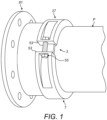
- FIGS 1 to 5 illustrate a pipe coupling or connector in accordance with a first embodiment of the present invention.
- the pipe coupling comprises an annular gripper ring 3 which receives a pipe P therewithin, and a clamp 7 which acts to apply a radially-inward compressive load on the gripper ring 3 in order to displace the gripper ring 3 against an external peripheral surface S of a wall W of the pipe P, as will be described in more detail hereinbelow.
- the gripper ring 3 comprises a gripper 11 which is inserted into the external surface S of the pipe P when the gripper ring 3 is clamped to the pipe P by operation of the clamp 7, and a carrier 15 which supports the gripper 11 with a defined orient in relation to the external surface S of the pipe P.
- the gripper 11 comprises a plurality of blade elements 17, which are arranged in circumferential relation and, when clamped to the pipe P by the clamp 7, are inserted into the external surface S of the pipe P, here cutting into the external surface S of the pipe P.
- the blade elements 17 each have a main body section 17a by which the blade element 17 is supported with a predetermined orient in relation to the external surface S of the pipe P, an external edge section 17b by which the blade element 17 is displaced inwardly during operation of the clamp 7, and an internal edge section 17c which provides a blade 18 which is inserted into the external surface S of the pipe P, here cutting into the external surface S of the pipe P, in order to engage the pipe P.
- the blade elements 17 are configured such that the blades 18 are inserted into the external surface S of the pipe P at a predetermined angle thereto.
- the blades 18 are inclined in relation to the external surface S of the pipe P, as illustrated in Figure 2 , such that the blades 18 each enclose an acute angle ⁇ with the external surface S of the pipe P rearwardly of the point of insertion of the blade 18 in relation to the distal end of the pipe P.
- the insertion angle ⁇ is 65 degrees.
- the insertion angle ⁇ is at least about 50 degrees.
- the insertion angle ⁇ is at least about 55 degrees.
- the insertion angle ⁇ is not greater than about 80 degrees.
- Figure 7 shows the relationship of the maximum axial load which can be withstood by the pipe coupling, where the blade elements 17 are arranged in symmetrical relation, with insertion angles ⁇ of 50, 60, 70 and 80 degrees.
- insertion angles ⁇ of 50, 60, 70 and 80 degrees.
- the blade elements 17 are inserted a predetermined depth d into the wall W of the pipe P, as illustrated in Figure 3 , with the insertion depth d being less than 10% of the thickness of the wall W of the pipe P.
- the blade elements 17 could be inserted 3.5 mm into the wall W of the pipe P.
- the blades 18 each comprise first and second spaced blade sections 18a, b, which allow the blade 18 to conform the outer peripheral surface S of the pipe P when displaced inwardly by operation of the clamp 7.
- the blade sections 18a, b are coupled by a web section 19, here of V shape, which supports the blade sections 18a, b in the axial direction and enables relative movement of the blade sections 18a, b in the radial direction, such as to promote preferential movement in relation to the web section 19 during compression of the gripper 11 and thereby promote uniform displacement of the blade elements 17.
- the blades 18 together define an inner opening 21 which has a diameter greater than the outer diameter of the pipe P, as illustrated in Figure 2 , thereby facilitating fitting of the pipe coupling to the pipe P, especially when the pipe P is out of round.
- the diameter of the inner opening 21 is such as to allow for the pipe P being 3% out of round from the nominal outer diameter, optionally being 5% out of round.
- the blades 18 form a substantially-continuous annular ring.
- the blades 18 are located at spaced locations about the gripper ring 3, with the arrangement and spacing therebetween being determined by the operational loading of the pipe P. In one embodiment the blades 18 have a space therebetween of at least half the width of the blades 18, optionally at least the width of the blades 18, and optionally at least twice the width of the blades 18.
- the blade elements 17 are formed of sheet material, here a spring stainless steel.
- the blade elements 17 could be formed of a coated mild steel.
- At least the inner edge sections 17c of the blade elements 17 are formed of sheet material.
- the gripper 11 is formed from a single sheet, here by a stamping operation, but could alternatively be formed by other cutting and bending operations, with adjacent ones of the blade elements 17 being interconnected by web elements 23, here in the form of strips.
- the web elements 23 comprise sections 23a, b which are inclined in relation to the radial direction, such as to promote preferential bending of the web elements 23 during compression of the gripper 11 and thereby promote uniform displacement of the blade elements 17.
- blade elements 17 could be formed as separate elements which are not interconnected.
- the blade elements 17 comprise at least one, here first and second guides 25, which are arranged in relation to the edge of the blade 18, such that, on insertion of the blade element 17 to the required extent into the wall W of the pipe P, the guides 25 abut the external surface S of the pipe P, thereby providing a clear visual indication to the operator when the clamp 7 is applied to the required extent.
- the clamp 7 comprises an annular body 27 which includes a recess 29 which captively receives the gripper ring 3, in this embodiment being defined by first and second flange members 31, 33 which are spaced in axial relation.
- the carrier 15 comprises at least one, here first and second support members 37a, b, which act to sandwich the gripper 11 therebetween.
- the support members 37a, b each have a support surface 39, and the support surfaces 39 receive the main bodies 17a of the blade elements 17 therebetween, such as to orient the blade elements 17 at the predetermined insertion angle ⁇ .
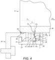
- the pipe coupling of the present invention operates by displacement of the blade elements 17 by application of a radial load F1, such that the blade elements 17 are inserted into the wall W of the pipe P to a predetermined extent, which does not require the maintenance of a high crush loading on the pipe P.
- the pipe P will be subjected to an axial load F2, which the pipe coupling is configured to withstand.
- F2 the pipe coupling is configured to withstand.
- the blades 18 of the blade elements 17 are configured to pivot and elastically deform, as illustrated in Figure 4 where the blade 18 pivots through an angle ⁇ in relation to the insertion angle ⁇ , allowing the pipe coupling to withstand a significant axial load F2, and to return to the original configuration on release of the axial load F2.
- the clamp 7 comprises a ring clamp and the clamp body 27 has open ends 53, with a fixing 55, here a bolt arrangement, connecting the open ends 53 and being operative to provide for closure of the annular body 27 and thus clamping of the gripper ring 3.
- the clamp 7 could be a multi-segment clamp comprising a plurality of clamp body parts 27 with adjacent open ends 53, and a plurality of fixings 55 which interconnect the same.
- the pipe coupling further comprises a coupling member 61 which is connected to the clamp 7 and provides for connection to a pipe component.
- the coupling member 61 comprises a flange adaptor, but could be any kind of pipe component.
- the pipe coupling further comprises an annular seal 63 which maintains a fluid-tight seal with the external surface of the pipe P.
- the coupling member 61 includes an annular recess 65, which receives the seal 63.
- the seal 63 is a lip seal, which utilizes the fluid pressure to maintain the seal, with an increasing sealing force being applied with increasing fluid pressure.
- existing pipe couplings necessitate the use of a compression seal, which relies on the compression force to achieve sealing, and does not provide for an increasing sealing force with increasing fluid pressure.
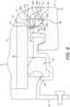
- FIGS 8 to 11 illustrate a pipe coupling in accordance with a second embodiment of the present invention.
- the pipe coupling of this embodiment is similar to the pipe coupling of the first-described embodiment, and thus, in order to avoid unnecessary duplication of description, only the differences will be described in detail, with like parts being designated by like reference signs.
- the blade elements 17 are separate elements, and omit the formed external edge section 17b.
- the carrier 15 comprises a plurality of recesses 75, which each provide the support surfaces 39, which support the main body sections 17a of the respective blade elements 17.
- the carrier 15 comprises a plurality of carrier members 77 which are disposed in the recess 29 in the annular body 27 of the clamp 7.
- the carrier members 77 each having oppositely-directed, axial faces 79a, b which engage the recess 29 in the annular body 27 of the clamp 7, oppositely-directed circumferential faces 83a, b, and oppositely-directed, inner and outer radial faces 84a, b.
- the carrier members 77 are interconnected, here interengaged, as an annulus which extends around the external surface S of the wall W of the pipe P.
- the carrier members 77 each have first and second engagement elements 85a, b, here male and female elements, by which adjacent ones of the carrier members 77 are interengaged.
- the engagement elements 85a, b are disposed to the circumferential faces 83a, b of the carrier member 77.
- the recess 29 in the annular body 27 of the clamp 7 has first and second opposed, axial faces 87a, b and an inner radial face 88, and the axial faces 87a, b of the annular body 27 of the clamp 7 and the axial faces 79a, b of the carrier members 77 are of corresponding tapered or wedge shape, maintaining the carrier members 77 in a fixed orientation in relation to the pipe P during the application of a radial load F1 to the clamp 7.
- the recess 29 in the annular body 27 of the clamp 7 and the carrier members 77 are configured to allow for limited radial displacement of the carrier members 77 in relation to clamp 7 during the application of a radial load F1 to the clamp 7, as will be described further hereinbelow.
- first faces 79a, 87a of the recess 29 and the carrier members 77 extend in a plane which is substantially perpendicular to the external surface S of the pipe P, and the other, second faces 79b, 87b of the recess 29 and the carrier members 77 are inclined outwardly in relation to the one, first faces 79a, 87a of the recess 29 and the carrier members 77.
- At least one of the axial faces 79a, b of the carrier members 77 includes at least one, here a plurality of first deformable elements 91, which are configured to maintain the relative orientation of the carrier members 77 but are deformable on application of a radial load F1 to the clamp 7, so as to enable the carrier members 77 to be displaced, to a limited extent, further into the recess 29 in the annular body 27 of the clamp 7.
- the first deformable elements 91 comprise an array of projections.
- the carrier members 77 each further include at least one, here a plurality of second deformable elements 93, which engage the inner radial face 88 of the recess 29 in the annular body 27 of the clamp 7 and, with the application of increasing radial load F1 during tightening of the clamp 7, can be deformed.
- This configuration allows the pipe coupling to accommodate the pipe P when out-of-round or having some ovality, in that the second deformable elements 93 of ones of the carrier members 77 which first engage the external surface S of the pipe P can be displaced outwardly in relation to the clamp 7 while the clamp 7 is continued to be tightened, until the clamp 7 is tightened sufficiently that the inner radial faces 84b of the carrier members 77 abut the external surface S of the wall of the pipe P.
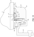
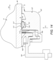
- the pipe coupling could comprise a plurality of grippers 11a, b which are arranged in spaced axial relation, here stacked relation, such as to provide for increased resistance to axial loading.
Landscapes
- Engineering & Computer Science (AREA)
- General Engineering & Computer Science (AREA)
- Mechanical Engineering (AREA)
- Quick-Acting Or Multi-Walled Pipe Joints (AREA)
- Mutual Connection Of Rods And Tubes (AREA)
- Flanged Joints, Insulating Joints, And Other Joints (AREA)
Priority Applications (3)
| Application Number | Priority Date | Filing Date | Title |
|---|---|---|---|
| HRP20250286TT HRP20250286T1 (hr) | 2016-10-21 | 2017-10-23 | Stezni prsten |
| RS20250256A RS66641B1 (sr) | 2016-10-21 | 2017-10-23 | Stezni prsten |
| SI201731597T SI3312489T1 (sl) | 2016-10-21 | 2017-10-23 | Prijemalni obroč |
Applications Claiming Priority (1)
| Application Number | Priority Date | Filing Date | Title |
|---|---|---|---|
| GB1617849.3A GB2555389B (en) | 2016-10-21 | 2016-10-21 | Pipe coupling |
Publications (3)
| Publication Number | Publication Date |
|---|---|
| EP3312489A2 EP3312489A2 (en) | 2018-04-25 |
| EP3312489A3 EP3312489A3 (en) | 2018-10-03 |
| EP3312489B1 true EP3312489B1 (en) | 2024-12-25 |
Family
ID=57738055
Family Applications (1)
| Application Number | Title | Priority Date | Filing Date |
|---|---|---|---|
| EP17197825.7A Active EP3312489B1 (en) | 2016-10-21 | 2017-10-23 | Gripper ring |
Country Status (12)
| Country | Link |
|---|---|
| US (1) | US11028950B2 (pl) |
| EP (1) | EP3312489B1 (pl) |
| CA (1) | CA2983244A1 (pl) |
| ES (1) | ES3015695T3 (pl) |
| FI (1) | FI3312489T3 (pl) |
| GB (1) | GB2555389B (pl) |
| HR (1) | HRP20250286T1 (pl) |
| HU (1) | HUE070581T2 (pl) |
| PL (1) | PL3312489T3 (pl) |
| PT (1) | PT3312489T (pl) |
| RS (1) | RS66641B1 (pl) |
| SI (1) | SI3312489T1 (pl) |
Families Citing this family (2)
| Publication number | Priority date | Publication date | Assignee | Title |
|---|---|---|---|---|
| US9689517B2 (en) * | 2010-09-23 | 2017-06-27 | Republic Conduit, Inc. | Tool-free metal conduit connector and related methods |
| KR102549182B1 (ko) * | 2021-11-11 | 2023-06-30 | 주식회사 피제이 용전 | 파이프 연결구 |
Citations (1)
| Publication number | Priority date | Publication date | Assignee | Title |
|---|---|---|---|---|
| US6206434B1 (en) * | 1998-01-24 | 2001-03-27 | Rasmussen Gmbh | Clampable pipe coupling |
Family Cites Families (38)
| Publication number | Priority date | Publication date | Assignee | Title |
|---|---|---|---|---|
| US2225208A (en) * | 1939-04-20 | 1940-12-17 | Merla Tod Company | Pipe coupling |
| US2459251A (en) * | 1945-06-30 | 1949-01-18 | Well Equipment Mfg Corp | Threadless pipe coupling |
| US2995388A (en) * | 1959-04-03 | 1961-08-08 | Cannon Electric Co | Gripping device |
| US2999701A (en) * | 1959-04-08 | 1961-09-12 | Chicago Forging & Mfg Co | Pipe coupling having sealing and anchoring means |
| US3582112A (en) * | 1969-04-14 | 1971-06-01 | Francisco A Pico | Fluid pressure-sealed pipe coupling |
| GB1392937A (en) * | 1971-11-15 | 1975-05-07 | Kelstan Plastic Products Ltd | Pipe coupling |
| US3790194A (en) * | 1972-08-02 | 1974-02-05 | Kelstan Plastic Prod Ltd | Pipe coupling |
| GB2167145B (en) * | 1984-11-21 | 1988-12-21 | Victaulic Plc | Improvements in or relating to pipe couplings and pipe joints formed therewith |
| CH667904A5 (de) * | 1985-06-17 | 1988-11-15 | Immanuel Straub | Rohrkupplung. |
| FR2649176B1 (fr) * | 1989-06-30 | 1994-03-25 | Pont A Mousson Sa | Garniture d'etancheite pour joints verrouilles etanches |
| GB9016489D0 (en) * | 1990-07-27 | 1990-09-12 | Taylor Kerr Couplings Ltd | Pipe coupling |
| FR2683609B1 (fr) * | 1991-11-07 | 1995-01-20 | Pont A Mousson | Joint verrouille pour canalisations. |
| JPH09317961A (ja) * | 1996-05-24 | 1997-12-12 | Yokohama Rubber Co Ltd:The | 管継手および管状体保持金具 |
| US5911446A (en) * | 1996-06-18 | 1999-06-15 | Victaulic Company Of America | Pipe coupling for plain ended pipe |
| US6357760B1 (en) | 2000-05-19 | 2002-03-19 | Michael Doyle | Ring seal |
| GB2363438B (en) | 2000-06-13 | 2004-08-25 | Glynwed Pipe Systems Ltd | Pipe coupling device with pipe gripping means |
| GB2363437B (en) * | 2000-06-13 | 2004-08-11 | Glynwed Pipe Systems Ltd | Method and apparatus for coupling pipe ends and a sealing and gripping assembly for the apparatus |
| US7121593B2 (en) * | 2001-01-19 | 2006-10-17 | Victaulic Company | Triple-expanded mechanical pipe coupling derived from a standard fitting |
| US6488319B2 (en) * | 2001-04-26 | 2002-12-03 | Jim Jones | Self restrained pressure gasket |
| DE10123924B4 (de) * | 2001-05-17 | 2006-01-26 | Rasmussen Gmbh | Rohrschelle, insbesondere Rohrkupplung |
| GB2401157B (en) * | 2002-02-20 | 2005-10-26 | Taylor Kerr | Anchoring device for pipe coupling |
| FR2883951B1 (fr) * | 2005-04-04 | 2007-08-17 | Yves Levivier | Manchon compensateur en elastomere sans bride et sans soudure pour reunir deux tubes lisses |
| AT504096B1 (de) * | 2006-07-17 | 2008-07-15 | Semperit Ag Holding | Dichtungsring und verbindungsvorrichtung für eine muffenverbindung |
| GB0703994D0 (en) * | 2007-03-01 | 2007-04-11 | Taylor Kerr Couplings Ltd | Anchoring arrangement for pipe coupling |
| US7571940B2 (en) * | 2007-12-04 | 2009-08-11 | Krausz Metal Industries Ltd. | Pipe coupling with built-in grip |
| KR20100034172A (ko) * | 2008-09-23 | 2010-04-01 | 주식회사 삼일엑슨 | 파이프 보조연결구 및 상기 파이프 보조연결구를 포함하는 파이프 연결구 |
| US9810358B2 (en) * | 2009-02-03 | 2017-11-07 | Aqseptence Group, Inc. | Male push lock pipe connection system |
| US8814219B2 (en) * | 2009-02-03 | 2014-08-26 | Bilfinger Water Technologies, Inc. | Push lock pipe connection system and disconnection tool |
| US10221977B2 (en) * | 2009-02-03 | 2019-03-05 | Aqseptence Group, Inc. | Pipe coupling |
| CA2731852C (en) * | 2011-02-16 | 2018-01-30 | Elisabet Patricia Pires Cabado | Improvements in flanges for the watertight coupling of smooth surface pipes |
| US20120274063A1 (en) * | 2011-04-29 | 2012-11-01 | Kennedy Jr Harold | Pipe connecting apparatus |
| AT511592B1 (de) * | 2011-09-19 | 2013-01-15 | E Hawle Armaturenwerke Gmbh | Rohrverbindungsvorrichtung und verfahren zu deren herstellung |
| FR2984985B1 (fr) * | 2011-12-23 | 2014-01-24 | Saint Gobain Pont A Mousson | Garniture d'etancheite et jonction tubulaire correspondante |
| CN105473923B (zh) * | 2013-07-17 | 2018-01-19 | 维克托里克公司 | 具有拱形刚度肋的配件 |
| GB2516452A (en) * | 2013-07-22 | 2015-01-28 | Jcco 331 Ltd | Improvements in and relating to pipe coupling |
| KR101468508B1 (ko) | 2013-08-29 | 2014-12-04 | 정우금속공업 주식회사 | 파이프 연결구 |
| FR3029260B1 (fr) * | 2014-12-01 | 2017-06-23 | Electrosteel Europe Sa | Garniture de joint a verrouillage mecanique comportant deux zones d'etancheite et sa mise en oeuvre pour realiser une jonction tubulaire flexible verrouillee |
| CN205261094U (zh) * | 2015-12-14 | 2016-05-25 | 安耐特流体输送科技有限公司 | 管道快插接头 |
-
2016
- 2016-10-21 GB GB1617849.3A patent/GB2555389B/en active Active
-
2017
- 2017-10-23 PT PT171978257T patent/PT3312489T/pt unknown
- 2017-10-23 EP EP17197825.7A patent/EP3312489B1/en active Active
- 2017-10-23 CA CA2983244A patent/CA2983244A1/en not_active Abandoned
- 2017-10-23 FI FIEP17197825.7T patent/FI3312489T3/fi active
- 2017-10-23 US US15/790,261 patent/US11028950B2/en active Active
- 2017-10-23 SI SI201731597T patent/SI3312489T1/sl unknown
- 2017-10-23 ES ES17197825T patent/ES3015695T3/es active Active
- 2017-10-23 RS RS20250256A patent/RS66641B1/sr unknown
- 2017-10-23 HR HRP20250286TT patent/HRP20250286T1/hr unknown
- 2017-10-23 PL PL17197825.7T patent/PL3312489T3/pl unknown
- 2017-10-23 HU HUE17197825A patent/HUE070581T2/hu unknown
Patent Citations (1)
| Publication number | Priority date | Publication date | Assignee | Title |
|---|---|---|---|---|
| US6206434B1 (en) * | 1998-01-24 | 2001-03-27 | Rasmussen Gmbh | Clampable pipe coupling |
Also Published As
| Publication number | Publication date |
|---|---|
| US20180112804A1 (en) | 2018-04-26 |
| ES3015695T3 (en) | 2025-05-07 |
| HUE070581T2 (hu) | 2025-06-28 |
| US11028950B2 (en) | 2021-06-08 |
| GB2555389A (en) | 2018-05-02 |
| FI3312489T3 (fi) | 2025-03-21 |
| SI3312489T1 (sl) | 2025-04-30 |
| EP3312489A2 (en) | 2018-04-25 |
| GB2555389B (en) | 2022-08-10 |
| PT3312489T (pt) | 2025-03-12 |
| RS66641B1 (sr) | 2025-04-30 |
| EP3312489A3 (en) | 2018-10-03 |
| CA2983244A1 (en) | 2018-04-21 |
| PL3312489T3 (pl) | 2025-06-09 |
| HRP20250286T1 (hr) | 2025-06-06 |
| GB201617849D0 (en) | 2016-12-07 |
Similar Documents
| Publication | Publication Date | Title |
|---|---|---|
| EP2959201B1 (en) | Coupling having arcuate stiffness ribs | |
| EP1292792B1 (en) | Pipe coupling device | |
| EP2470817B1 (en) | Press-connect fitting with improved grab-ring function | |
| US6902205B2 (en) | Coupling for composite pipe | |
| EP3022478B1 (en) | Fittings having arcuate stiffness ribs | |
| EP3338015B1 (en) | Combination of a pipe element and a sprinkler adapter | |
| EP2494249B1 (en) | Pipe coupling with seal pressing device | |
| JPH0253669B2 (pl) | ||
| WO2012128152A1 (ja) | 管継手 | |
| JPS6014692A (ja) | 高圧流路連結部 | |
| KR20170003660A (ko) | 조립을 촉진시키도록 적응된 부품을 구비한 도관 피팅 | |
| JP4766707B2 (ja) | プラスチック樹脂パイプ用の管継手 | |
| AU675584B2 (en) | Pipe connector | |
| US11028950B2 (en) | Pipe coupling | |
| EP0756120B1 (en) | Pipe coupling | |
| JP2011085162A (ja) | 管継手 | |
| KR200439127Y1 (ko) | 배관 조인트용 체결 압착 홀더 | |
| HK1212419B (en) | Coupling having arcuate stiffness ribs | |
| WO2013129933A1 (en) | Hub and connector arrangement |
Legal Events
| Date | Code | Title | Description |
|---|---|---|---|
| REG | Reference to a national code |
Ref country code: HR Ref legal event code: TUEP Ref document number: P20250286T Country of ref document: HR |
|
| PUAI | Public reference made under article 153(3) epc to a published international application that has entered the european phase |
Free format text: ORIGINAL CODE: 0009012 |
|
| STAA | Information on the status of an ep patent application or granted ep patent |
Free format text: STATUS: THE APPLICATION HAS BEEN PUBLISHED |
|
| AK | Designated contracting states |
Kind code of ref document: A2 Designated state(s): AL AT BE BG CH CY CZ DE DK EE ES FI FR GB GR HR HU IE IS IT LI LT LU LV MC MK MT NL NO PL PT RO RS SE SI SK SM TR |
|
| AX | Request for extension of the european patent |
Extension state: BA ME |
|
| PUAL | Search report despatched |
Free format text: ORIGINAL CODE: 0009013 |
|
| AK | Designated contracting states |
Kind code of ref document: A3 Designated state(s): AL AT BE BG CH CY CZ DE DK EE ES FI FR GB GR HR HU IE IS IT LI LT LU LV MC MK MT NL NO PL PT RO RS SE SI SK SM TR |
|
| AX | Request for extension of the european patent |
Extension state: BA ME |
|
| RIC1 | Information provided on ipc code assigned before grant |
Ipc: F16L 47/12 20060101ALN20180824BHEP Ipc: F16L 21/08 20060101AFI20180824BHEP |
|
| STAA | Information on the status of an ep patent application or granted ep patent |
Free format text: STATUS: REQUEST FOR EXAMINATION WAS MADE |
|
| 17P | Request for examination filed |
Effective date: 20190403 |
|
| RBV | Designated contracting states (corrected) |
Designated state(s): AL AT BE BG CH CY CZ DE DK EE ES FI FR GB GR HR HU IE IS IT LI LT LU LV MC MK MT NL NO PL PT RO RS SE SI SK SM TR |
|
| STAA | Information on the status of an ep patent application or granted ep patent |
Free format text: STATUS: EXAMINATION IS IN PROGRESS |
|
| 17Q | First examination report despatched |
Effective date: 20210517 |
|
| GRAP | Despatch of communication of intention to grant a patent |
Free format text: ORIGINAL CODE: EPIDOSNIGR1 |
|
| STAA | Information on the status of an ep patent application or granted ep patent |
Free format text: STATUS: GRANT OF PATENT IS INTENDED |
|
| INTG | Intention to grant announced |
Effective date: 20240718 |
|
| GRAS | Grant fee paid |
Free format text: ORIGINAL CODE: EPIDOSNIGR3 |
|
| GRAA | (expected) grant |
Free format text: ORIGINAL CODE: 0009210 |
|
| STAA | Information on the status of an ep patent application or granted ep patent |
Free format text: STATUS: THE PATENT HAS BEEN GRANTED |
|
| AK | Designated contracting states |
Kind code of ref document: B1 Designated state(s): AL AT BE BG CH CY CZ DE DK EE ES FI FR GB GR HR HU IE IS IT LI LT LU LV MC MK MT NL NO PL PT RO RS SE SI SK SM TR |
|
| REG | Reference to a national code |
Ref country code: GB Ref legal event code: FG4D |
|
| REG | Reference to a national code |
Ref country code: CH Ref legal event code: EP |
|
| REG | Reference to a national code |
Ref country code: DE Ref legal event code: R096 Ref document number: 602017086928 Country of ref document: DE |
|
| REG | Reference to a national code |
Ref country code: IE Ref legal event code: FG4D |
|
| REG | Reference to a national code |
Ref country code: PT Ref legal event code: SC4A Ref document number: 3312489 Country of ref document: PT Date of ref document: 20250312 Kind code of ref document: T Free format text: AVAILABILITY OF NATIONAL TRANSLATION Effective date: 20250306 |
|
| REG | Reference to a national code |
Ref country code: FI Ref legal event code: FGE |
|
| REG | Reference to a national code |
Ref country code: SE Ref legal event code: TRGR |
|
| REG | Reference to a national code |
Ref country code: NL Ref legal event code: FP |
|
| REG | Reference to a national code |
Ref country code: LT Ref legal event code: MG9D |
|
| REG | Reference to a national code |
Ref country code: GR Ref legal event code: EP Ref document number: 20250400593 Country of ref document: GR Effective date: 20250409 |
|
| REG | Reference to a national code |
Ref country code: HR Ref legal event code: T1PR Ref document number: P20250286 Country of ref document: HR |
|
| REG | Reference to a national code |
Ref country code: AT Ref legal event code: MK05 Ref document number: 1754418 Country of ref document: AT Kind code of ref document: T Effective date: 20241225 |
|
| REG | Reference to a national code |
Ref country code: HU Ref legal event code: AG4A Ref document number: E070581 Country of ref document: HU |
|
| PG25 | Lapsed in a contracting state [announced via postgrant information from national office to epo] |
Ref country code: SM Free format text: LAPSE BECAUSE OF FAILURE TO SUBMIT A TRANSLATION OF THE DESCRIPTION OR TO PAY THE FEE WITHIN THE PRESCRIBED TIME-LIMIT Effective date: 20241225 |
|
| PG25 | Lapsed in a contracting state [announced via postgrant information from national office to epo] |
Ref country code: IS Free format text: LAPSE BECAUSE OF FAILURE TO SUBMIT A TRANSLATION OF THE DESCRIPTION OR TO PAY THE FEE WITHIN THE PRESCRIBED TIME-LIMIT Effective date: 20250425 |
|
| PG25 | Lapsed in a contracting state [announced via postgrant information from national office to epo] |
Ref country code: EE Free format text: LAPSE BECAUSE OF FAILURE TO SUBMIT A TRANSLATION OF THE DESCRIPTION OR TO PAY THE FEE WITHIN THE PRESCRIBED TIME-LIMIT Effective date: 20241225 |
|
| PG25 | Lapsed in a contracting state [announced via postgrant information from national office to epo] |
Ref country code: AT Free format text: LAPSE BECAUSE OF FAILURE TO SUBMIT A TRANSLATION OF THE DESCRIPTION OR TO PAY THE FEE WITHIN THE PRESCRIBED TIME-LIMIT Effective date: 20241225 Ref country code: RO Free format text: LAPSE BECAUSE OF FAILURE TO SUBMIT A TRANSLATION OF THE DESCRIPTION OR TO PAY THE FEE WITHIN THE PRESCRIBED TIME-LIMIT Effective date: 20241225 |
|
| PG25 | Lapsed in a contracting state [announced via postgrant information from national office to epo] |
Ref country code: SK Free format text: LAPSE BECAUSE OF FAILURE TO SUBMIT A TRANSLATION OF THE DESCRIPTION OR TO PAY THE FEE WITHIN THE PRESCRIBED TIME-LIMIT Effective date: 20241225 |
|
| REG | Reference to a national code |
Ref country code: DE Ref legal event code: R097 Ref document number: 602017086928 Country of ref document: DE |
|
| PG25 | Lapsed in a contracting state [announced via postgrant information from national office to epo] |
Ref country code: DK Free format text: LAPSE BECAUSE OF FAILURE TO SUBMIT A TRANSLATION OF THE DESCRIPTION OR TO PAY THE FEE WITHIN THE PRESCRIBED TIME-LIMIT Effective date: 20241225 |
|
| PGFP | Annual fee paid to national office [announced via postgrant information from national office to epo] |
Ref country code: GB Payment date: 20250929 Year of fee payment: 9 |
|
| PGFP | Annual fee paid to national office [announced via postgrant information from national office to epo] |
Ref country code: IE Payment date: 20250929 Year of fee payment: 9 |
|
| PGFP | Annual fee paid to national office [announced via postgrant information from national office to epo] |
Ref country code: SI Payment date: 20251009 Year of fee payment: 9 |
|
| PLBE | No opposition filed within time limit |
Free format text: ORIGINAL CODE: 0009261 |
|
| STAA | Information on the status of an ep patent application or granted ep patent |
Free format text: STATUS: NO OPPOSITION FILED WITHIN TIME LIMIT |
|
| REG | Reference to a national code |
Ref country code: HR Ref legal event code: ODRP Ref document number: P20250286 Country of ref document: HR Payment date: 20251009 Year of fee payment: 9 |
|
| PGFP | Annual fee paid to national office [announced via postgrant information from national office to epo] |
Ref country code: HU Payment date: 20251027 Year of fee payment: 9 |
|
| PGFP | Annual fee paid to national office [announced via postgrant information from national office to epo] |
Ref country code: NL Payment date: 20251021 Year of fee payment: 9 |
|
| 26N | No opposition filed |
Effective date: 20250926 |
|
| PGFP | Annual fee paid to national office [announced via postgrant information from national office to epo] |
Ref country code: PT Payment date: 20251009 Year of fee payment: 9 |
|
| PGFP | Annual fee paid to national office [announced via postgrant information from national office to epo] |
Ref country code: DE Payment date: 20251021 Year of fee payment: 9 |
|
| PGFP | Annual fee paid to national office [announced via postgrant information from national office to epo] |
Ref country code: NO Payment date: 20251024 Year of fee payment: 9 |
|
| PGFP | Annual fee paid to national office [announced via postgrant information from national office to epo] |
Ref country code: MK Payment date: 20251013 Year of fee payment: 9 |
|
| PGFP | Annual fee paid to national office [announced via postgrant information from national office to epo] |
Ref country code: FI Payment date: 20251028 Year of fee payment: 9 Ref country code: IT Payment date: 20251021 Year of fee payment: 9 |
|
| PGFP | Annual fee paid to national office [announced via postgrant information from national office to epo] |
Ref country code: HR Payment date: 20251009 Year of fee payment: 9 Ref country code: FR Payment date: 20251030 Year of fee payment: 9 |
|
| PGFP | Annual fee paid to national office [announced via postgrant information from national office to epo] |
Ref country code: BE Payment date: 20251021 Year of fee payment: 9 Ref country code: GR Payment date: 20251022 Year of fee payment: 9 |
|
| PGFP | Annual fee paid to national office [announced via postgrant information from national office to epo] |
Ref country code: SE Payment date: 20251021 Year of fee payment: 9 |
|
| PGFP | Annual fee paid to national office [announced via postgrant information from national office to epo] |
Ref country code: CZ Payment date: 20251015 Year of fee payment: 9 |
|
| PGFP | Annual fee paid to national office [announced via postgrant information from national office to epo] |
Ref country code: LV Payment date: 20251015 Year of fee payment: 9 |
|
| PGFP | Annual fee paid to national office [announced via postgrant information from national office to epo] |
Ref country code: BG Payment date: 20251023 Year of fee payment: 9 Ref country code: PL Payment date: 20251010 Year of fee payment: 9 |
|
| PGFP | Annual fee paid to national office [announced via postgrant information from national office to epo] |
Ref country code: RO Payment date: 20251013 Year of fee payment: 9 |
|
| PGFP | Annual fee paid to national office [announced via postgrant information from national office to epo] |
Ref country code: RS Payment date: 20251009 Year of fee payment: 9 |
|
| PGFP | Annual fee paid to national office [announced via postgrant information from national office to epo] |
Ref country code: ES Payment date: 20251216 Year of fee payment: 9 |
|
| PG2D | Information on lapse in contracting state deleted |
Ref country code: RO |