EP3312427A1 - Ventilator mit ventilatorrad und leitrad - Google Patents
Ventilator mit ventilatorrad und leitrad Download PDFInfo
- Publication number
- EP3312427A1 EP3312427A1 EP17189145.0A EP17189145A EP3312427A1 EP 3312427 A1 EP3312427 A1 EP 3312427A1 EP 17189145 A EP17189145 A EP 17189145A EP 3312427 A1 EP3312427 A1 EP 3312427A1
- Authority
- EP
- European Patent Office
- Prior art keywords
- fan
- stator
- flow direction
- fan according
- axial flow
- Prior art date
- Legal status (The legal status is an assumption and is not a legal conclusion. Google has not performed a legal analysis and makes no representation as to the accuracy of the status listed.)
- Granted
Links
Images

Classifications
-
- F—MECHANICAL ENGINEERING; LIGHTING; HEATING; WEAPONS; BLASTING
- F04—POSITIVE - DISPLACEMENT MACHINES FOR LIQUIDS; PUMPS FOR LIQUIDS OR ELASTIC FLUIDS
- F04D—NON-POSITIVE-DISPLACEMENT PUMPS
- F04D29/00—Details, component parts, or accessories
- F04D29/26—Rotors specially for elastic fluids
- F04D29/32—Rotors specially for elastic fluids for axial flow pumps
- F04D29/325—Rotors specially for elastic fluids for axial flow pumps for axial flow fans
- F04D29/329—Details of the hub
-
- F—MECHANICAL ENGINEERING; LIGHTING; HEATING; WEAPONS; BLASTING
- F04—POSITIVE - DISPLACEMENT MACHINES FOR LIQUIDS; PUMPS FOR LIQUIDS OR ELASTIC FLUIDS
- F04D—NON-POSITIVE-DISPLACEMENT PUMPS
- F04D19/00—Axial-flow pumps
- F04D19/002—Axial flow fans
-
- F—MECHANICAL ENGINEERING; LIGHTING; HEATING; WEAPONS; BLASTING
- F04—POSITIVE - DISPLACEMENT MACHINES FOR LIQUIDS; PUMPS FOR LIQUIDS OR ELASTIC FLUIDS
- F04D—NON-POSITIVE-DISPLACEMENT PUMPS
- F04D29/00—Details, component parts, or accessories
- F04D29/40—Casings; Connections of working fluid
- F04D29/52—Casings; Connections of working fluid for axial pumps
- F04D29/54—Fluid-guiding means, e.g. diffusers
- F04D29/541—Specially adapted for elastic fluid pumps
- F04D29/542—Bladed diffusers
-
- F—MECHANICAL ENGINEERING; LIGHTING; HEATING; WEAPONS; BLASTING
- F04—POSITIVE - DISPLACEMENT MACHINES FOR LIQUIDS; PUMPS FOR LIQUIDS OR ELASTIC FLUIDS
- F04D—NON-POSITIVE-DISPLACEMENT PUMPS
- F04D29/00—Details, component parts, or accessories
- F04D29/40—Casings; Connections of working fluid
- F04D29/52—Casings; Connections of working fluid for axial pumps
- F04D29/54—Fluid-guiding means, e.g. diffusers
- F04D29/541—Specially adapted for elastic fluid pumps
- F04D29/542—Bladed diffusers
- F04D29/544—Blade shapes
-
- F—MECHANICAL ENGINEERING; LIGHTING; HEATING; WEAPONS; BLASTING
- F04—POSITIVE - DISPLACEMENT MACHINES FOR LIQUIDS; PUMPS FOR LIQUIDS OR ELASTIC FLUIDS
- F04D—NON-POSITIVE-DISPLACEMENT PUMPS
- F04D29/00—Details, component parts, or accessories
- F04D29/40—Casings; Connections of working fluid
- F04D29/52—Casings; Connections of working fluid for axial pumps
- F04D29/54—Fluid-guiding means, e.g. diffusers
- F04D29/541—Specially adapted for elastic fluid pumps
- F04D29/545—Ducts
-
- F—MECHANICAL ENGINEERING; LIGHTING; HEATING; WEAPONS; BLASTING
- F15—FLUID-PRESSURE ACTUATORS; HYDRAULICS OR PNEUMATICS IN GENERAL
- F15D—FLUID DYNAMICS, i.e. METHODS OR MEANS FOR INFLUENCING THE FLOW OF GASES OR LIQUIDS
- F15D1/00—Influencing flow of fluids
- F15D1/02—Influencing flow of fluids in pipes or conduits
-
- F—MECHANICAL ENGINEERING; LIGHTING; HEATING; WEAPONS; BLASTING
- F04—POSITIVE - DISPLACEMENT MACHINES FOR LIQUIDS; PUMPS FOR LIQUIDS OR ELASTIC FLUIDS
- F04D—NON-POSITIVE-DISPLACEMENT PUMPS
- F04D29/00—Details, component parts, or accessories
- F04D29/66—Combating cavitation, whirls, noise, vibration or the like; Balancing
- F04D29/661—Combating cavitation, whirls, noise, vibration or the like; Balancing especially adapted for elastic fluid pumps
- F04D29/667—Combating cavitation, whirls, noise, vibration or the like; Balancing especially adapted for elastic fluid pumps by influencing the flow pattern, e.g. suppression of turbulence
Definitions
- the invention relates to a fan with a fan and a stator.
- An object of the invention is therefore to provide a fan with Lachleitrad that allows a compact axial design while improving the flow characteristics.
- a ventilator with fan blades having fan blades which extends radially outward about an axis of rotation of the fan and whose radial outer circumference determines a ventilator wheel diameter.
- the fan also includes a spaced in the axial flow direction to the fan wheel with Heilleitstegen, which also extends radially outward and has a Leitrad mismesser which is smaller than the Lüfterrad mismesser, so that the stator determines a partial cross-sectional area of a Lüfterradquerexcellents constitutional.
- stator can be mounted as a retrofit part of existing fans due to the low space requirement.
- Another advantageous aspect of the reduced in diameter relative to the fan wheel stator is that the pressure difference across the smaller cross-section of the stator is lower, so that the risk of freezing is reduced when used in refrigeration.
- the fan wheel has a fan wheel hub and a flow-through blade section which adjoins the fan wheel hub in the radial direction to the outer circumference of the fan wheel.
- the stator comprises a Leitradnabe and a subsequent in the radial direction of the Leitradnabe to the outer periphery of the stator guide section. It is advantageous if the diameter ratio of the guide section to the blade section is in a range of 0.1 to 0.8, more preferably in a range of 0.2 to 0.5.
- the Leitradnabe no separate component must be provided, but the Leitradnabe can also be formed by elements of other components, such as a motor housing.
- the stator is formed in the axial flow direction with a width which is 0.01 to 0.2 (ie 1% -20%) of the fan wheel diameter, more preferably 0.02 to 0.1 (ie 2% -10%).
- the fan wheel diameter corresponds. This means that the reference variable for adjusting the width of the stator is the fan wheel diameter.
- the geometric design of the stator has immediate fluidic effects, with the dimensions described above, both individually and cumulatively, causing the turbulent components and the radial component in the radially inner region of the air flow generated by the fan to be reduced.
- the outflow angle in the meridional plane approaches substantially the optimum value zero, so that the usually occurring in the hub or radial inner region return flow is eliminated against the generated flow direction.
- stator and the compact design are further promoted by the fact that the minimum distance in the axial flow direction between the fan wheel and the stator in a range of 0.01 and 0.2, more preferably in a range of 0.01 and 0th , 05 of the fan wheel diameter is.
- stator has an outer peripheral ring at its radial outer circumference.
- the outer peripheral ring is preferably thin-walled and has a radial thickness which corresponds to 0.002 to 0.015 of the fan wheel diameter.
- the outer peripheral ring is formed completely circumferentially around the stator and in axial section has a non-cornered cross-section. In addition to a fluidic influence of the outer peripheral ring then also promotes a rigidity increase of the stator.
- a further embodiment of the fan is characterized in that the Leitradnabe relative to the axis of rotation at an angle ⁇ of up to 60 ° employed in the axial flow direction extends radially outward, i. the Leitradnabe is conically shaped in the flow direction.
- the stator has, in radial direction adjacent to the stator hub, an inner ring which adjusts to the axis of rotation at an angle ⁇ of up to 60 ° in the axial flow direction, preferably over the entire width of the stator, extends radially outward.
- the employment of the Leitradnabe or adjacent to the Leitradnabe inner ring guides the air flow generated by the fan in the radial inner region in the direction radially outward from the axis of rotation of the fan away.
- stator hub or the inner ring forms a nozzle with a flow-reducing cross-section reducing the outer peripheral ring.
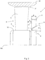
- FIG. 1 is shown in axial section the upper half of a (axial) fan 1 with a about the rotation axis RA of the fan 1 radially outwardly extending fan wheel 2 and arranged in the axial flow direction at a very small distance A to the fan wheel 2 stator 4 wherein the distance A corresponds to a value of 0.02 of the fan wheel diameter Dv.
- the lower, not shown half of the fan 1 is mirror-symmetrical.
- the fan wheel 2 has a plurality of circumferentially spaced fan blades 3, each extending radially from the fan hub 12 to the outside, thereby increasing their axial width.
- alternative, known from the art forms of the fan blades are used.
- a flow channel forming a housing part 30 is indicated, in which the fan 1 is inserted with a gap spacing 31 between the fan blades 3 and the inner wall of the housing part 30.
- the housing part 30 may be an external component or integrated in the fan.
- the stator 4 includes a plurality of axially extending through the stator Lucasleitstege 5 and extends from the Leitradnabe 13 radially outward to the outer peripheral ring 11.
- the maximum stator diameter DI is less than the Lüfterrad micr Dv. Since the stator 4 and the fan wheel 2 are arranged to overlap in the flow direction, the stator 4 determines a flow-through partial cross-sectional area of the ventilator cross-sectional area through which can flow.
- the permeable cross-sectional areas are formed by the radially outwardly extending from the Lüfterradnabe 12 blade portion 8 and the Leitradnabe 13 radially outwardly extending guide portion 9, wherein the diameter ratio of the guide portion 9 to the blade section 8 in the embodiment shown is 0.4.
- the radially outer part of the blade section 8 is not covered by the stator 4, so that the flow generated by the fan 2 partially passes first through the stator 4, partly immediately after axially outside.
- the outer peripheral ring 11 extends parallel to the axis of rotation RA substantially over the entire width B of the stator 4 and is formed as a thin-walled circumferential ring whose thickness corresponds to a value of 0.01 of the fan diameter Dv.
- the width B of the stator 4 corresponds to a value of 0.065 of the fan wheel diameter Dv.
- the Lüfterradnabe 12 and the Leitradnabe 13 have the same hub diameter Dn.
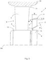
- the execution according to Fig. 2 is to the one in FIG. 1 identical to the design of the stator, so that to avoid repetition on the FIG. 1 described features.
- the stator 4 of the embodiment according to FIG. 3 additionally comprises an inner ring 7 which has a relative to the axis of rotation RA at the angle ⁇ of 40 ° employed section and extends in the axial flow direction over the entire width B of the stator 4 obliquely radially outward.
- the inner ring 7 has a V-shaped cross section with a leg acting on the stator hub 13 and a leg forming the engaged portion.
- the inner ring 7 effectively prevents axial backflow of air in the direction of the fan wheel 2 in the radially inner, adjacent to the hubs 12, 13 region.
- FIG. 3 The execution according to Fig. 3 is identical to the one in FIG. 2 until, that the outer peripheral ring 11 is modified. To avoid repetition is therefore to the disclosure of the FIGS. 1 and 2 Referenced.
- the stator 4 thus forms, through the inner ring 7 and the outer peripheral ring 11, a nozzle with a flow cross-section which decreases in the flow direction. Due to the inclination of the outer peripheral ring 11, the maximum Leitradquerites increases by the length of the counter-catheter of the angle ⁇ .
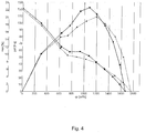
- FIG. 4 is a diagram with curves to the pressure curve psf [Pa] and the efficiency nse [%] at different volume flows qv [m 3 / h] of the fan 1 according to Fig. 1 and the same fan without stator 4, wherein the solid curves in each case the fan 1 according to FIG. 1 and the dashed curves each identify the fan without a stator.
- the advantageous effect with increased peak efficiency at a flow rate of about 1100 m 3 / h and higher pressure to about 1300 m 3 / h, ie in the highly relevant operating range, can be clearly seen.
Landscapes
- Engineering & Computer Science (AREA)
- Mechanical Engineering (AREA)
- General Engineering & Computer Science (AREA)
- Physics & Mathematics (AREA)
- Geometry (AREA)
- Fluid Mechanics (AREA)
- Structures Of Non-Positive Displacement Pumps (AREA)
Abstract
Description
- Die Erfindung betrifft einen Ventilator mit einem Ventilatorrad und einem Leitrad.
- Die Verwendung von Leiträdern bei Ventilatoren ist aus dem Stand der Technik bekannt. Beispielsweise offenbart die
DE 10 2012 109 542 A1 einen Axiallüfter mit einem als Strömungsgleichrichter ausgebildeten Leitrad, das im technischen Fachgebiet auch als Nachleitrad bezeichnet wird. - Bei den bekannten Leiträdern ist man davon ausgegangen, dass sie ihre größte strömungstechnische und geräuschreduzierende Wirkung in einem radial äußeren Bereich von Ventilatoren bzw. Ventilatorrädern gewährleisten, da in diesem Bereich die Geschwindigkeit der von dem Ventilator erzeugten Luftströmung maximal ist. Das Leitrad soll die Strömung vergleichmäßigen und eine sich negativ auf den Wirkungsgrad und das Geräuschverhalten auswirkende Rückströmung zum Ventilatorrad verhindern. Die bekannte Lösung des oben genannten Stands funktioniert in der Praxis gut, kann jedoch noch weiter verbessert werden, um weitere positive Aspekte bezüglich des benötigen axialen Bauraums, des Strömungsverlaufs und des Geräuschverhaltens zu erzielen.
- Eine Aufgabe der Erfindung ist deshalb, einen Ventilator mit Lachleitrad bereit zu stellen, der eine kompakte axiale Bauweise bei gleichzeitig verbessernder Strömungscharaktereristik ermöglicht.
- Diese Aufgabe wird durch die Merkmalskombination gemäß Patentanspruch 1 gelöst.
- Erfindungsgemäß wird ein Ventilator mit einem Ventilatorschaufeln aufweisenden Ventilatorrad vorgeschlagen, das sich um eine Rotationsachse des Ventilators nach radial außen erstreckt und dessen radialer Außenumfang einen Ventilatorraddurchmesser bestimmt. Der Ventilator umfasst zudem ein in axialer Strömungsrichtung zu dem Ventilatorrad in einem Abstand angeordnetes Leitrad mit Luftleitstegen, das sich ebenfalls nach radial außen erstreckt und einen Leitraddurchmesser aufweist, der geringer ist als der Ventilatorraddurchmesser, so dass das Leitrad eine Teilquerschnittfläche einer Ventilatorradquerschnittsfläche bestimmt.
- Durch das gegenüber dem Ventilatorrad im Durchmesser kleinere Leitrad ist es möglich, den Abstand zwischen dem Ventilatorrad und dem Leitrad zu reduzieren, d.h. das Leitrad in Strömungsrichtung näher an das Ventilatorrad zu positionieren. Dies reduziert zum einen die Baugröße des Ventilators in axialer Strömungsrichtung, zum anderen verbessert sich sein Geräuschverhalten. Die grundsätzlich bekannte Wirkung der Vergleichmäßigung der Strömung und Verhinderung der Rückströmung bleiben ohnedies erhalten.
- Zudem kann das Leitrad aufgrund des geringen Bauraumbedarfs als nachrüstbares Teil an bestehende Ventilatoren montiert werden.
- Ein weiterer vorteilhafter Aspekt des im Durchmesser gegenüber dem Ventilatorrad reduzierten Leitrads liegt darin, dass die Druckdifferenz über den kleineren Querschnitt des Leitrads geringer ist, so dass die Vereisungsgefahr bei einer Anwendung in der Kältetechnik reduziert wird.
- In einer vorteilhaften Ausführung des Ventilators ist vorgesehen, dass das Ventilatorrad eine Ventilatorradnabe und einen sich in radialer Richtung an die Ventilatorradnabe bis zum Außenumfang des Ventilatorrades anschließenden durchströmbaren Schaufelabschnitt aufweist. Zudem umfasst das Leitrad eine Leitradnabe und einen sich in radialer Richtung an die Leitradnabe bis zum Außenumfang des Leitrades anschließenden Leitabschnitt. Dabei ist vorteilhaft, wenn das Durchmesserverhältnis des Leitabschnitts zum Schaufelabschnitt in einem Bereich von 0,1 bis 0,8, weiter bevorzugt in einem Bereich von 0,2 bis 0,5 liegt. Als Leitradnabe muss kein eigenes Bauteil vorgesehen werden, vielmehr kann die Leitradnabe auch durch Elemente anderer Bauteile, beispielsweise ein Motorgehäuse ausgebildet werden.
- In einer Weiterbildung wird das Leitrad in axialer Strömungsrichtung mit einer Breite ausgebildet, die 0,01 bis 0,2 (d.h. 1% - 20%) des Ventilatorraddurchmessers, weiter bevorzugt 0,02 bis 0,1 (d.h. 2% - 10%) des Ventilatorraddurchmessers entspricht. Das bedeutet, dass die Bezugsgröße zur Anpassung der Breite des Leitrads der Ventilatorraddurchmesser ist.
- Die geometrische Ausbildung des Leitrads hat unmittelbare strömungstechnische Auswirkungen, wobei die vorstehend beschriebenen Dimensionierungen sowohl einzeln als auch kumulativ dazu führen, dass die turbulenten Anteile und die radiale Komponente im radialen Innenbereich der von dem Ventilator erzeugten Luftströmung verringert werden. Der Ausströmungswinkel in der Meridianebene nähert sich im Wesentlichen dem optimalen Wert Null an, so dass die üblicherweise im Naben- bzw. radialen Innenbereich auftretende Rückströmung entgegen der erzeugten Strömungsrichtung beseitigt wird.
- Die positive Wirkung des Leitrads und die kompakte Bauweise werden ferner dadurch gefördert, dass der minimale Abstand in axialer Strömungsrichtung zwischen dem Ventilatorrad und dem Leitrad in einem Bereich von 0,01 und 0,2, weiter bevorzugt in einem Bereich von 0,01 und 0,05 des Ventilatorraddurchmessers liegt.
- Strömungstechnisch günstig ist zudem eine Ausführungsvariante, bei der das Leitrad an seinem radialen Außenumfang einen Außenumfangsring aufweist. Der Außenumfangsring ist vorzugsweise dünnwandig ausgebildet und weist eine radiale Dicke auf, die 0,002 bis 0,015 des Ventilatorraddurchmessers entspricht.
- Ferner ist vorteilhaft, wenn der Außenumfangsring vollständig um das Leitrad umlaufend ausgebildet ist und im Axialschnitt einen nichteckigen Querschnitt aufweist. Neben einem strömungstechnischen Einfluss begünstigt der Außenumfangsring dann zudem eine Steifigkeitserhöhung des Leitrads.
- In einer vorteilhaften Weiterbildung wird vorgesehen, dass der Außenumfangsring gegenüber der Rotationsachse in einem Winkel β von 5 - 25°, weiter bevorzugt von 5 - 10° angestellt in axialer Strömungsrichtung nach radial außen verläuft.
- Eine weitere Ausführungsvariante des Ventilator ist dadurch gekennzeichnet, dass die Leitradnabe gegenüber der Rotationsachse in einem Winkel α von bis zu 60° angestellt in axialer Strömungsrichtung nach radial außen verläuft, d.h. die Leitradnabe ist in Strömungsrichtung kegelförmig ausgebildet.
- Alternativ zur Leitradnabe kann in einer alternative Lösung vorgesehen werden, dass das Leitrad in radialer an die Leitradnabe angrenzend einen Innenring aufweist, der zur Rotationsachse in einem Winkel α von bis zu 60° angestellt in axialer Strömungsrichtung, vorzugsweise über die gesamte Breite des Leitrads, nach radial außen verläuft. Das Anstellen der Leitradnabe bzw. des sich an die Leitradnabe angrenzenden Innenrings führt die von dem Ventilatorrad erzeugte Luftströmung im radialen Innenbereich in Richtung nach radial außen von der Rotationsachse des Ventilators weg.
- Als vorteilhaft hat sich zudem eine Ausgestaltung erwiesen, bei der der Winkel α größer als der Winkel β ist.
- Strömungstechnisch ist weiterhin eine Ausführung günstig, bei der die Leitradnabe oder der Innenring mit dem Außenumfangsring eine Düse mit sich in Strömungsrichtung verringerndem Durchströmungsquerschnitt bildet.
- Die Ausführung der Luftleitstege des Leitrads erfolgt vorzugsweise in einer Weise gemäß der Offenbarung der
DE102012109542A1 . Der diesbezügliche Offenbarungsgehalt wird Bestandteil der vorliegenden Offenbarung. Weitere für den Ventilator standardmäßig vorzusehende Bauteile wie z.B. ein Motor und eine Antriebswelle sind ebenfalls umfasst, auch wenn sie nicht ausdrücklich beschrieben werden. Andere vorteilhafte Weiterbildungen der Erfindung sind in den Unteransprüchen gekennzeichnet bzw. werden nachstehend zusammen mit der Beschreibung der bevorzugten Ausführung der Erfindung anhand der Figuren näher dargestellt. Es zeigen: - Fig. 1
- eine schematische hälftig geschnittene Seitenansicht eines erfindungsgemäßen Ventilators;
- Fig. 2
- eine schematische hälftig geschnittene Seitenansicht eines erfindungsgemäßen Ventilators in einer weiteren Ausführungsvariante,
- Fig. 3
- eine schematische hälftig geschnittene Seitenansicht eines erfindungsgemäßen Ventilators in einer weiteren Ausführungsvariante,
- Fig. 4
- ein Diagramm mit Kurvenverläufen des Ventilators gemäß
Fig. 1 und dem Stand der Technik ohne Leitrad. - Gleiche Bezugszeichen benennen gleich Teile in allen Ansichten. Alle Figuren sind rein schematisch und dienen dem Verständnis der Erfindung.
- In
Figur 1 ist im Axialschnitt die obere Hälfte eines als (Axial-)Ventilators 1 mit einem sich um die Rotationsachse RA des Ventilators 1 nach radial außen erstreckenden Ventilatorrad 2 sowie einem in axialer Strömungsrichtung in einem sehr geringen Abstand A zu dem Ventilatorrad 2 angeordneten Leitrad 4 gezeigt, wobei der Abstand A einem Wert von 0,02 des Ventilatorraddurchmessers Dv entspricht. Die untere, nicht gezeigte Hälfte des Ventilators 1 ist spiegelsymmetrisch ausgebildet. Das Ventilatorrad 2 weist mehrere in Umfangsrichtung zueinander beabstandet angeordnete Ventilatorschaufeln 3 auf, die sich jeweils von der Ventilatorradnabe 12 radial nach außen erstrecken und dabei ihre axiale Breite vergrößern. Für alle Ausführungsbeispiele sind auch alternative, aus der Technik bekannte Formen der Ventilatorschaufeln einsetzbar. Das radial äußere freie Ende der Ventilatorradschaufeln 3 bestimmt den Außenumfang und mithin den Ventilatorraddurchmessers Dv. Zudem ist ein einen Strömungskanal ausbildendes Gehäuseteil 30 angedeutet, in den der Ventilator 1 mit einem Spaltabstand 31 zwischen Ventilatorschaufeln 3 und Innenwand des Gehäuseteils 30 eingesetzt ist. Das Gehäuseteil 30 kann ein externes Bauteil oder in den Ventilator integriert sein. - Das Leitrad 4 umfasst eine Vielzahl von in axialer Richtung durch das Leitrad verlaufende Luftleitstege 5 und erstreckt sich von der Leitradnabe 13 nach radial außen bis zum Außenumfangsring 11. Der maximale Leitraddurchmesser DI ist geringer ist als der Ventilatorraddurchmesser Dv. Da das Leitrad 4 und das Ventilatorrad 2 sich in Strömungsrichtung überdeckend angeordnet sind, bestimmt das Leitrad 4 eine durchströmbare Teilquerschnittfläche der durchströmbaren Ventilatorradquerschnittsfläche. Die durchströmbaren Querschnittsflächen werden durch den sich von der Ventilatorradnabe 12 nach radial außen erstreckenden Schaufelabschnitt 8 und den sich von der Leitradnabe 13 nach radial außen erstreckenden Leitabschnitt 9 gebildet, wobei das Durchmesserverhältnis des Leitabschnitts 9 zum Schaufelabschnitt 8 in der gezeigten Ausführung bei 0,4 liegt. Der radial äußere Teil des Schaufelabschnitts 8 ist von dem Leitrad 4 nicht überdeckt, so dass die von dem Ventilatorrad 2 erzeugte Strömung teilweise zunächst durch das Leitrad 4, teilweise unmittelbar nach axial außen gelangt.
- Der Außenumfangsring 11 verläuft parallel zur Rotationsachse RA im Wesentlichen über die gesamte Breite B des Leitrads 4 und ist als dünnwandiger umlaufender Ring ausgebildet, dessen Dicke einem Wert von 0,01 des Ventilatorraddurchmessers Dv entspricht. Die Breite B des Leitrads 4 entspricht einem Wert von 0,065 des Ventilatorraddurchmessers Dv. Die Ventilatorradnabe 12 und die Leitradnabe 13 weisen denselben Nabendurchmesser Dn auf.
- Die Ausführung gemäß
Fig. 2 ist zu derjenigen inFigur 1 bis auf die Ausbildung des Leitrads identisch, so dass zur Vermeidung von Wiederholungen auf die zuFigur 1 beschriebenen Merkmale Bezug genommen wird. Das Leitrad 4 der Ausführung gemäßFigur 3 umfasst zusätzlich einen Innenring 7, der einen gegenüber der Rotationsachse RA im Winkel α von 40° angestellten Abschnitt aufweist und in axialer Strömungsrichtung über die gesamte Breite B des Leitrads 4 schräg nach radial außen verläuft. Im gezeigten Axialschnitt weist der Innenring 7 einen V-förmigen Querschnitt mit einem an die Leitradnabe 13 angreifenden Schenkel und einem den angestellten Abschnitt bildenden Schenkel auf. Der Innenring 7 verhindert effektiv eine axiale Rückströmung von Luft in Richtung des Ventilatorrades 2 im radial innen liegenden, an die Naben 12, 13 angrenzenden Bereich. - Die Ausführung gemäß
Fig. 3 ist identisch zu derjenigen inFigur 2 bis auf, dass der Außenumfangsring 11 abgewandelt ist. Zur Vermeidung von Wiederholungen wird deshalb auf die Offenbarung zu denFiguren 1 und2 Bezug genommen. GemäßFigur 3 ist der Außenumfangsring 11 gegenüber der Rotationsachse RA in einem Winkel β=10° angestellt und verläuft in axialer Strömungsrichtung nach radial außen. Das Leitrad 4 bildet somit durch den Innenring 7 und den Außenumfangsring 11 eine Düse mit sich in Strömungsrichtung verringerndem Durchströmungsquerschnitt. Aufgrund der Schrägstellung des Außenumfangsrings 11 vergrößert sich der maximale Leitradquerschnitt um die Länge der Gegenkathete des Winkels β. - In
Figur 4 ist ein Diagramm mit Kennlinien zum Druckverlauf psf [Pa] und dem Wirkungsgrad nse [%] bei unterschiedlichen Volumenströmen qv [m3/h] des Ventilators 1 gemäßFig. 1 und desselben Ventilators ohne Leitrad 4 dargestellt, wobei die durchgezogenen Kennlinien jeweils den Ventilator 1 gemäßFigur 1 und die gestrichelten Kennlinien jeweils den Ventilator ohne Leitrad kennzeichnen. Die vorteilhafte Wirkung mit erhöhtem Spitzwirkungsgrad bei einem Volumenstrom von ca. 1100 m3/h und höherem Druck bis ca. 1300 m3/h, d.h. im hochrelevanten Betriebsbereich, ist eindeutig zu entnehmen.
Claims (15)
- Ventilator mit einem Ventilatorschaufeln (3) aufweisenden Ventilatorrad (2), das sich um eine Rotationsachse des Ventilators (1) nach radial außen erstreckt und dessen radialer Außenumfang einen Ventilatorraddurchmesser (Dv) bestimmt, und einem in axialer Strömungsrichtung zu dem Ventilatorrad (1) in einem Abstand (A) angeordneten Leitrad (4) mit Luftleitstegen (5), das sich nach radial außen erstreckt und einen Leitraddurchmesser (DI) aufweist, der geringer ist als der Ventilatorraddurchmesser (Dv), so dass das Leitrad (4) eine Teilquerschnittfläche einer Ventilatorradquerschnittsfläche bestimmt.
- Ventilator nach Anspruch 1, dadurch gekennzeichnet, dass das Ventilatorrad (2) eine Ventilatorradnabe (12) und einen sich in radialer Richtung an die Ventilatorradnabe (12) bis zum Außenumfang des Ventilatorrades (2) anschließenden Schaufelabschnitt (8) aufweist, und das Leitrad (4) eine Leitradnabe (13) und einen sich in radialer Richtung an die Leitradnabe (13) bis zum Außenumfang des Leitrades (4) anschließenden Leitabschnitt (9) aufweist, wobei ein Durchmesserverhältnis des Leitabschnitts (9) zum Schaufelabschnitt (8) in einem Bereich von 0,1 bis 0,8 liegt.
- Ventilator nach Anspruch 2, dadurch gekennzeichnet, dass das Durchmesserverhältnis des Leitabschnitts (9) zum Schaufelabschnitt (8) in einem Bereich von 0,2 bis 0,5 liegt.
- Ventilator nach einem der vorigen Ansprüche, dadurch gekennzeichnet, dass das Leitrad (4) in axialer Strömungsrichtung eine Breite (B) aufweist, die 0,01 bis 0,2 des Ventilatorraddurchmessers (Dv) entspricht.
- Ventilator nach dem vorigen Anspruch, dadurch gekennzeichnet, dass das das Leitrad (4) in axialer Strömungsrichtung eine Breite (B) aufweist, die in einem Bereich von 0,02 bis 0,1 des Ventilatorraddurchmessers (Dv) liegt.
- Ventilator nach einem der vorigen Ansprüche, dadurch gekennzeichnet, dass der Abstand (A) in axialer Strömungsrichtung zwischen dem Ventilatorrad (2) und dem Leitrad (4) in einem Bereich von 0,01 und 0,2, vorzugsweise in einem Bereich von 0,01 und 0,05 des Ventilatorraddurchmessers (Dv) liegt.
- Ventilator nach einem der vorigen Ansprüche, dadurch gekennzeichnet, dass das Leitrad (4) an seinem radialen Außenumfang einen Außenumfangsring (11) aufweist.
- Ventilator nach dem vorigen Anspruch, dadurch gekennzeichnet, dass der Außenumfangsring (11) eine radiale Dicke aufweist, die 0,002 bis 0,015 des Ventilatorraddurchmessers (Dv) entspricht.
- Ventilator nach einem der vorigen beiden Ansprüche, dadurch gekennzeichnet, dass der Außenumfangsring (11) vollständig um das Leitrad (4) umlaufend ausgebildet ist und im Axialschnitt einen nichteckigen Querschnitt aufweist.
- Ventilator nach einem der vorigen Ansprüche 7 bis 9, dadurch gekennzeichnet, dass der Außenumfangsring (11) gegenüber der Rotationsachse in einem Winkel β von 5 - 25° angestellt in axialer Strömungsrichtung nach radial außen verläuft.
- Ventilator nach einem der vorigen Ansprüche 7 bis 10, dadurch gekennzeichnet, dass der Außenumfangsring (11) gegenüber der Rotationsachse in einem Winkel β von 5 - 10° angestellt in axialer Strömungsrichtung nach radial außen verläuft.
- Ventilator nach einem der vorigen Ansprüche 2 bis 11, dadurch gekennzeichnet, dass die Leitradnabe (13) gegenüber der Rotationsachse in einem Winkel α von bis zu 60° angestellt in axialer Strömungsrichtung nach radial außen verläuft.
- Ventilator nach einem der vorigen Ansprüche 2 bis 11, dadurch gekennzeichnet, dass das Leitrad (4) in radialer Richtung an die Leitradnabe (13) angrenzend einen Innenring (7) aufweist, der zur Rotationsachse in einem Winkel α von 0 - 60° angestellt in axialer Strömungsrichtung über die gesamte Breite (B) des Leitrads (4) nach radial außen verläuft.
- Ventilator nach einem der vorigen Ansprüche 10 bis 13, dadurch gekennzeichnet, dass der Winkel α größer als der Winkel β ist.
- Ventilator nach einem der vorigen Ansprüche 2 bis 14, dadurch gekennzeichnet, dass die Leitradnabe (13) mit dem Außenumfangsring (11) eine Düse mit sich in Strömungsrichtung verringerndem Durchströmungsquerschnitt bildet.
Applications Claiming Priority (1)
| Application Number | Priority Date | Filing Date | Title |
|---|---|---|---|
| DE102016119916.8A DE102016119916A1 (de) | 2016-10-19 | 2016-10-19 | Ventilator mit Ventilatorrad und Leitrad |
Publications (3)
| Publication Number | Publication Date |
|---|---|
| EP3312427A1 true EP3312427A1 (de) | 2018-04-25 |
| EP3312427B1 EP3312427B1 (de) | 2022-08-17 |
| EP3312427B2 EP3312427B2 (de) | 2025-10-01 |
Family
ID=59251473
Family Applications (1)
| Application Number | Title | Priority Date | Filing Date |
|---|---|---|---|
| EP17189145.0A Active EP3312427B2 (de) | 2016-10-19 | 2017-09-04 | Ventilator mit ventilatorrad und leitrad |
Country Status (4)
| Country | Link |
|---|---|
| US (1) | US10428829B2 (de) |
| EP (1) | EP3312427B2 (de) |
| CN (1) | CN206309653U (de) |
| DE (1) | DE102016119916A1 (de) |
Families Citing this family (3)
| Publication number | Priority date | Publication date | Assignee | Title |
|---|---|---|---|---|
| DE102015205424A1 (de) * | 2015-03-25 | 2016-09-29 | Ebm-Papst Mulfingen Gmbh & Co. Kg | Nachleitrad |
| WO2017192647A1 (en) * | 2016-05-03 | 2017-11-09 | Carrier Corporation | Inlet for axial fan |
| DE102018211808A1 (de) * | 2018-07-16 | 2020-01-16 | Ziehl-Abegg Se | Ventilator und Leiteinrichtung für einen Ventilator |
Citations (3)
| Publication number | Priority date | Publication date | Assignee | Title |
|---|---|---|---|---|
| DE10330088A1 (de) * | 2003-07-03 | 2005-02-03 | Asia Vital Components Co., Ltd. | Luftumlenkung bzw. Führung zur Beeinflussung der Windrichtung einer Wärmeabführung |
| US20060067816A1 (en) * | 2004-09-24 | 2006-03-30 | Bor-Haw Chang | Cooling fan with fluid control device |
| WO2011151323A2 (de) * | 2010-06-01 | 2011-12-08 | Esg Mbh | Kanal mit strömungsleitfläche |
Family Cites Families (18)
| Publication number | Priority date | Publication date | Assignee | Title |
|---|---|---|---|---|
| CH219997A (de) | 1941-02-17 | 1942-03-15 | Ventilator A G | Ventilator. |
| GB766216A (en) | 1954-03-05 | 1957-01-16 | Stork Koninklijke Maschf | Improvements in and relating to pumps or fans provided with an axial flow impeller |
| US3536414A (en) | 1968-03-06 | 1970-10-27 | Gen Electric | Vanes for turning fluid flow in an annular duct |
| DK345883D0 (da) * | 1983-07-28 | 1983-07-28 | Nordisk Ventilator | Aksialventilator |
| DE4404262A1 (de) | 1994-02-10 | 1995-08-17 | Guentner Gmbh Hans | Schutzgittervorrichtung für Ventilatoren, insbesondere von Luftkühlern |
| US6514052B2 (en) * | 2001-03-30 | 2003-02-04 | Emerson Electric Co. | Two sided radial fan for motor cooling |
| US6599088B2 (en) * | 2001-09-27 | 2003-07-29 | Borgwarner, Inc. | Dynamically sealing ring fan shroud assembly |
| US20050186070A1 (en) | 2004-02-23 | 2005-08-25 | Ling-Zhong Zeng | Fan assembly and method |
| US7381129B2 (en) | 2004-03-15 | 2008-06-03 | Airius, Llc. | Columnar air moving devices, systems and methods |
| US7484925B2 (en) | 2005-05-10 | 2009-02-03 | Emp Advanced Development, Llc | Rotary axial fan assembly |
| DE102005046180B3 (de) | 2005-09-27 | 2007-03-22 | Siemens Ag | Lüftermodul |
| US7478993B2 (en) | 2006-03-27 | 2009-01-20 | Valeo, Inc. | Cooling fan using Coanda effect to reduce recirculation |
| JP5199849B2 (ja) * | 2008-12-05 | 2013-05-15 | 三菱重工業株式会社 | 車両用熱交換モジュールおよびこれを備えた車両 |
| DE202011004708U1 (de) | 2010-08-12 | 2011-07-14 | Ziehl-Abegg Ag | Ventilator |
| EP2541068B1 (de) * | 2011-06-29 | 2016-08-10 | ebm-papst Mulfingen GmbH & Co. KG | Axialventilator mit Strömungsleitkörper |
| CN103696987B (zh) | 2012-09-27 | 2016-05-11 | 台达电子工业股份有限公司 | 风扇及其增压扇叶组 |
| DE102012109542A1 (de) | 2012-10-08 | 2014-04-10 | Ebm-Papst Mulfingen Gmbh & Co. Kg | "Strömungsgleichrichter für einen Axiallüfter" |
| US10330121B2 (en) * | 2015-02-26 | 2019-06-25 | Honeywell International Inc. | Systems and methods for axial compressor with secondary flow |
-
2016
- 2016-10-19 DE DE102016119916.8A patent/DE102016119916A1/de active Pending
- 2016-12-15 CN CN201621378057.6U patent/CN206309653U/zh active Active
-
2017
- 2017-09-04 EP EP17189145.0A patent/EP3312427B2/de active Active
- 2017-10-18 US US15/786,842 patent/US10428829B2/en active Active
Patent Citations (3)
| Publication number | Priority date | Publication date | Assignee | Title |
|---|---|---|---|---|
| DE10330088A1 (de) * | 2003-07-03 | 2005-02-03 | Asia Vital Components Co., Ltd. | Luftumlenkung bzw. Führung zur Beeinflussung der Windrichtung einer Wärmeabführung |
| US20060067816A1 (en) * | 2004-09-24 | 2006-03-30 | Bor-Haw Chang | Cooling fan with fluid control device |
| WO2011151323A2 (de) * | 2010-06-01 | 2011-12-08 | Esg Mbh | Kanal mit strömungsleitfläche |
Also Published As
| Publication number | Publication date |
|---|---|
| US10428829B2 (en) | 2019-10-01 |
| US20180106267A1 (en) | 2018-04-19 |
| EP3312427B1 (de) | 2022-08-17 |
| CN206309653U (zh) | 2017-07-07 |
| DE102016119916A1 (de) | 2018-04-19 |
| EP3312427B2 (de) | 2025-10-01 |
Similar Documents
| Publication | Publication Date | Title |
|---|---|---|
| DE102011121996B4 (de) | Vorrichtung zum Betrieb eines Verdichters | |
| EP3775565B1 (de) | Kompakter diagonalventilator mit nachleiteinrichtung | |
| EP3824190B1 (de) | Ventilator und leiteinrichtung für einen ventilator | |
| EP1712800B1 (de) | Lüfterrad | |
| EP2418389A2 (de) | Flügelrad für einen Ventilator | |
| EP2466150B1 (de) | Verfahren zur Herstellung eines Flügelrades für einen Ventilator | |
| WO2017017264A1 (de) | Lüfterrad und kühlerlüftermodul | |
| EP3571416B1 (de) | Gedecktes radialgebläserad mit einer periodisch und asymmetrisch geformten scheibe | |
| EP3312427B1 (de) | Ventilator mit ventilatorrad und leitrad | |
| DE202016105863U1 (de) | Ventilator mit Ventilatorrad und Leitrad | |
| EP2133574A2 (de) | Räumliches Schutzgitter für Axiallüfter und Verfahren zur Herstellung des Schutzgitters | |
| EP2994614A1 (de) | Rotor für eine thermische strömungsmaschine | |
| DE102014219058A1 (de) | Radialverdichterlaufrad und zugehöriger Radialverdichter | |
| EP4430310A1 (de) | Ventilator und kühlstruktur für einen ventilator | |
| EP3009682A1 (de) | Axialventilator mit aussen- und innendiffusor | |
| DE112011101494T5 (de) | Verdichter eines Abgasturboladers | |
| DE212009000007U1 (de) | Radiallüfter | |
| DE102019101277A1 (de) | Axiallüfteranordnung für Fahrzeuge | |
| DE102008052981A1 (de) | Leitschaufel eines Axialverdichters | |
| DE1161481B (de) | Einrichtung zur Stabilisierung der Charakteristik von Kreiselradarbeitsmaschinen mit axialdurchstroemtem Laufrad | |
| WO2016046112A1 (de) | Radialverdichterlaufrad und zugehöriger radialverdichter | |
| DE102014118210B4 (de) | Mehrflutige Strömungsmaschine | |
| EP3997345B1 (de) | Ventilator mit spiralgehäuse | |
| EP0143235B1 (de) | Leitradloser Axialventilator, insbesondere zur Belüftung von Wärmetauschern | |
| DE8207204U1 (de) | Axialgeblaese, insbesonder fuer kuehler einer wassergekuehlten brennkraftmaschine |
Legal Events
| Date | Code | Title | Description |
|---|---|---|---|
| PUAI | Public reference made under article 153(3) epc to a published international application that has entered the european phase |
Free format text: ORIGINAL CODE: 0009012 |
|
| STAA | Information on the status of an ep patent application or granted ep patent |
Free format text: STATUS: THE APPLICATION HAS BEEN PUBLISHED |
|
| AK | Designated contracting states |
Kind code of ref document: A1 Designated state(s): AL AT BE BG CH CY CZ DE DK EE ES FI FR GB GR HR HU IE IS IT LI LT LU LV MC MK MT NL NO PL PT RO RS SE SI SK SM TR |
|
| AX | Request for extension of the european patent |
Extension state: BA ME |
|
| STAA | Information on the status of an ep patent application or granted ep patent |
Free format text: STATUS: REQUEST FOR EXAMINATION WAS MADE |
|
| 17P | Request for examination filed |
Effective date: 20180813 |
|
| RBV | Designated contracting states (corrected) |
Designated state(s): AL AT BE BG CH CY CZ DE DK EE ES FI FR GB GR HR HU IE IS IT LI LT LU LV MC MK MT NL NO PL PT RO RS SE SI SK SM TR |
|
| STAA | Information on the status of an ep patent application or granted ep patent |
Free format text: STATUS: EXAMINATION IS IN PROGRESS |
|
| 17Q | First examination report despatched |
Effective date: 20200331 |
|
| GRAP | Despatch of communication of intention to grant a patent |
Free format text: ORIGINAL CODE: EPIDOSNIGR1 |
|
| STAA | Information on the status of an ep patent application or granted ep patent |
Free format text: STATUS: GRANT OF PATENT IS INTENDED |
|
| INTG | Intention to grant announced |
Effective date: 20220406 |
|
| GRAS | Grant fee paid |
Free format text: ORIGINAL CODE: EPIDOSNIGR3 |
|
| GRAA | (expected) grant |
Free format text: ORIGINAL CODE: 0009210 |
|
| STAA | Information on the status of an ep patent application or granted ep patent |
Free format text: STATUS: THE PATENT HAS BEEN GRANTED |
|
| AK | Designated contracting states |
Kind code of ref document: B1 Designated state(s): AL AT BE BG CH CY CZ DE DK EE ES FI FR GB GR HR HU IE IS IT LI LT LU LV MC MK MT NL NO PL PT RO RS SE SI SK SM TR |
|
| REG | Reference to a national code |
Ref country code: CH Ref legal event code: EP |
|
| REG | Reference to a national code |
Ref country code: DE Ref legal event code: R096 Ref document number: 502017013620 Country of ref document: DE |
|
| REG | Reference to a national code |
Ref country code: IE Ref legal event code: FG4D Free format text: LANGUAGE OF EP DOCUMENT: GERMAN |
|
| REG | Reference to a national code |
Ref country code: AT Ref legal event code: REF Ref document number: 1512372 Country of ref document: AT Kind code of ref document: T Effective date: 20220915 |
|
| REG | Reference to a national code |
Ref country code: NL Ref legal event code: FP |
|
| REG | Reference to a national code |
Ref country code: LT Ref legal event code: MG9D |
|
| PG25 | Lapsed in a contracting state [announced via postgrant information from national office to epo] |
Ref country code: SE Free format text: LAPSE BECAUSE OF FAILURE TO SUBMIT A TRANSLATION OF THE DESCRIPTION OR TO PAY THE FEE WITHIN THE PRESCRIBED TIME-LIMIT Effective date: 20220817 Ref country code: RS Free format text: LAPSE BECAUSE OF FAILURE TO SUBMIT A TRANSLATION OF THE DESCRIPTION OR TO PAY THE FEE WITHIN THE PRESCRIBED TIME-LIMIT Effective date: 20220817 Ref country code: PT Free format text: LAPSE BECAUSE OF FAILURE TO SUBMIT A TRANSLATION OF THE DESCRIPTION OR TO PAY THE FEE WITHIN THE PRESCRIBED TIME-LIMIT Effective date: 20221219 Ref country code: NO Free format text: LAPSE BECAUSE OF FAILURE TO SUBMIT A TRANSLATION OF THE DESCRIPTION OR TO PAY THE FEE WITHIN THE PRESCRIBED TIME-LIMIT Effective date: 20221117 Ref country code: LV Free format text: LAPSE BECAUSE OF FAILURE TO SUBMIT A TRANSLATION OF THE DESCRIPTION OR TO PAY THE FEE WITHIN THE PRESCRIBED TIME-LIMIT Effective date: 20220817 Ref country code: LT Free format text: LAPSE BECAUSE OF FAILURE TO SUBMIT A TRANSLATION OF THE DESCRIPTION OR TO PAY THE FEE WITHIN THE PRESCRIBED TIME-LIMIT Effective date: 20220817 Ref country code: FI Free format text: LAPSE BECAUSE OF FAILURE TO SUBMIT A TRANSLATION OF THE DESCRIPTION OR TO PAY THE FEE WITHIN THE PRESCRIBED TIME-LIMIT Effective date: 20220817 |
|
| PG25 | Lapsed in a contracting state [announced via postgrant information from national office to epo] |
Ref country code: PL Free format text: LAPSE BECAUSE OF FAILURE TO SUBMIT A TRANSLATION OF THE DESCRIPTION OR TO PAY THE FEE WITHIN THE PRESCRIBED TIME-LIMIT Effective date: 20220817 Ref country code: IS Free format text: LAPSE BECAUSE OF FAILURE TO SUBMIT A TRANSLATION OF THE DESCRIPTION OR TO PAY THE FEE WITHIN THE PRESCRIBED TIME-LIMIT Effective date: 20221217 Ref country code: HR Free format text: LAPSE BECAUSE OF FAILURE TO SUBMIT A TRANSLATION OF THE DESCRIPTION OR TO PAY THE FEE WITHIN THE PRESCRIBED TIME-LIMIT Effective date: 20220817 Ref country code: GR Free format text: LAPSE BECAUSE OF FAILURE TO SUBMIT A TRANSLATION OF THE DESCRIPTION OR TO PAY THE FEE WITHIN THE PRESCRIBED TIME-LIMIT Effective date: 20221118 |
|
| PG25 | Lapsed in a contracting state [announced via postgrant information from national office to epo] |
Ref country code: SM Free format text: LAPSE BECAUSE OF FAILURE TO SUBMIT A TRANSLATION OF THE DESCRIPTION OR TO PAY THE FEE WITHIN THE PRESCRIBED TIME-LIMIT Effective date: 20220817 Ref country code: RO Free format text: LAPSE BECAUSE OF FAILURE TO SUBMIT A TRANSLATION OF THE DESCRIPTION OR TO PAY THE FEE WITHIN THE PRESCRIBED TIME-LIMIT Effective date: 20220817 Ref country code: ES Free format text: LAPSE BECAUSE OF FAILURE TO SUBMIT A TRANSLATION OF THE DESCRIPTION OR TO PAY THE FEE WITHIN THE PRESCRIBED TIME-LIMIT Effective date: 20220817 Ref country code: DK Free format text: LAPSE BECAUSE OF FAILURE TO SUBMIT A TRANSLATION OF THE DESCRIPTION OR TO PAY THE FEE WITHIN THE PRESCRIBED TIME-LIMIT Effective date: 20220817 Ref country code: CZ Free format text: LAPSE BECAUSE OF FAILURE TO SUBMIT A TRANSLATION OF THE DESCRIPTION OR TO PAY THE FEE WITHIN THE PRESCRIBED TIME-LIMIT Effective date: 20220817 |
|
| REG | Reference to a national code |
Ref country code: CH Ref legal event code: PL |
|
| REG | Reference to a national code |
Ref country code: DE Ref legal event code: R026 Ref document number: 502017013620 Country of ref document: DE |
|
| PLBI | Opposition filed |
Free format text: ORIGINAL CODE: 0009260 |
|
| REG | Reference to a national code |
Ref country code: BE Ref legal event code: MM Effective date: 20220930 |
|
| PG25 | Lapsed in a contracting state [announced via postgrant information from national office to epo] |
Ref country code: SK Free format text: LAPSE BECAUSE OF FAILURE TO SUBMIT A TRANSLATION OF THE DESCRIPTION OR TO PAY THE FEE WITHIN THE PRESCRIBED TIME-LIMIT Effective date: 20220817 Ref country code: MC Free format text: LAPSE BECAUSE OF FAILURE TO SUBMIT A TRANSLATION OF THE DESCRIPTION OR TO PAY THE FEE WITHIN THE PRESCRIBED TIME-LIMIT Effective date: 20220817 Ref country code: EE Free format text: LAPSE BECAUSE OF FAILURE TO SUBMIT A TRANSLATION OF THE DESCRIPTION OR TO PAY THE FEE WITHIN THE PRESCRIBED TIME-LIMIT Effective date: 20220817 |
|
| PLAX | Notice of opposition and request to file observation + time limit sent |
Free format text: ORIGINAL CODE: EPIDOSNOBS2 |
|
| 26 | Opposition filed |
Opponent name: ZIEHL-ABEGG SE Effective date: 20230515 |
|
| P01 | Opt-out of the competence of the unified patent court (upc) registered |
Effective date: 20230522 |
|
| PG25 | Lapsed in a contracting state [announced via postgrant information from national office to epo] |
Ref country code: LU Free format text: LAPSE BECAUSE OF NON-PAYMENT OF DUE FEES Effective date: 20220904 Ref country code: AL Free format text: LAPSE BECAUSE OF FAILURE TO SUBMIT A TRANSLATION OF THE DESCRIPTION OR TO PAY THE FEE WITHIN THE PRESCRIBED TIME-LIMIT Effective date: 20220817 |
|
| PG25 | Lapsed in a contracting state [announced via postgrant information from national office to epo] |
Ref country code: LI Free format text: LAPSE BECAUSE OF NON-PAYMENT OF DUE FEES Effective date: 20220930 Ref country code: IE Free format text: LAPSE BECAUSE OF NON-PAYMENT OF DUE FEES Effective date: 20220904 Ref country code: CH Free format text: LAPSE BECAUSE OF NON-PAYMENT OF DUE FEES Effective date: 20220930 |
|
| PG25 | Lapsed in a contracting state [announced via postgrant information from national office to epo] |
Ref country code: SI Free format text: LAPSE BECAUSE OF FAILURE TO SUBMIT A TRANSLATION OF THE DESCRIPTION OR TO PAY THE FEE WITHIN THE PRESCRIBED TIME-LIMIT Effective date: 20220817 |
|
| PLBB | Reply of patent proprietor to notice(s) of opposition received |
Free format text: ORIGINAL CODE: EPIDOSNOBS3 |
|
| PG25 | Lapsed in a contracting state [announced via postgrant information from national office to epo] |
Ref country code: BE Free format text: LAPSE BECAUSE OF NON-PAYMENT OF DUE FEES Effective date: 20220930 |
|
| PG25 | Lapsed in a contracting state [announced via postgrant information from national office to epo] |
Ref country code: HU Free format text: LAPSE BECAUSE OF FAILURE TO SUBMIT A TRANSLATION OF THE DESCRIPTION OR TO PAY THE FEE WITHIN THE PRESCRIBED TIME-LIMIT; INVALID AB INITIO Effective date: 20170904 |
|
| PG25 | Lapsed in a contracting state [announced via postgrant information from national office to epo] |
Ref country code: CY Free format text: LAPSE BECAUSE OF FAILURE TO SUBMIT A TRANSLATION OF THE DESCRIPTION OR TO PAY THE FEE WITHIN THE PRESCRIBED TIME-LIMIT Effective date: 20220817 |
|
| PG25 | Lapsed in a contracting state [announced via postgrant information from national office to epo] |
Ref country code: MK Free format text: LAPSE BECAUSE OF FAILURE TO SUBMIT A TRANSLATION OF THE DESCRIPTION OR TO PAY THE FEE WITHIN THE PRESCRIBED TIME-LIMIT Effective date: 20220817 |
|
| PG25 | Lapsed in a contracting state [announced via postgrant information from national office to epo] |
Ref country code: TR Free format text: LAPSE BECAUSE OF FAILURE TO SUBMIT A TRANSLATION OF THE DESCRIPTION OR TO PAY THE FEE WITHIN THE PRESCRIBED TIME-LIMIT Effective date: 20220817 |
|
| PG25 | Lapsed in a contracting state [announced via postgrant information from national office to epo] |
Ref country code: BG Free format text: LAPSE BECAUSE OF FAILURE TO SUBMIT A TRANSLATION OF THE DESCRIPTION OR TO PAY THE FEE WITHIN THE PRESCRIBED TIME-LIMIT Effective date: 20220817 |
|
| PG25 | Lapsed in a contracting state [announced via postgrant information from national office to epo] |
Ref country code: MT Free format text: LAPSE BECAUSE OF FAILURE TO SUBMIT A TRANSLATION OF THE DESCRIPTION OR TO PAY THE FEE WITHIN THE PRESCRIBED TIME-LIMIT Effective date: 20220817 |
|
| APAH | Appeal reference modified |
Free format text: ORIGINAL CODE: EPIDOSCREFNO |
|
| APAW | Appeal reference deleted |
Free format text: ORIGINAL CODE: EPIDOSDREFNO |
|
| APAY | Date of receipt of notice of appeal deleted |
Free format text: ORIGINAL CODE: EPIDOSDNOA2O |
|
| APBP | Date of receipt of notice of appeal recorded |
Free format text: ORIGINAL CODE: EPIDOSNNOA2O |
|
| APBU | Appeal procedure closed |
Free format text: ORIGINAL CODE: EPIDOSNNOA9O |
|
| PUAH | Patent maintained in amended form |
Free format text: ORIGINAL CODE: 0009272 |
|
| STAA | Information on the status of an ep patent application or granted ep patent |
Free format text: STATUS: PATENT MAINTAINED AS AMENDED |
|
| 27A | Patent maintained in amended form |
Effective date: 20251001 |
|
| AK | Designated contracting states |
Kind code of ref document: B2 Designated state(s): AL AT BE BG CH CY CZ DE DK EE ES FI FR GB GR HR HU IE IS IT LI LT LU LV MC MK MT NL NO PL PT RO RS SE SI SK SM TR |
|
| REG | Reference to a national code |
Ref country code: DE Ref legal event code: R102 Ref document number: 502017013620 Country of ref document: DE |
|
| PGFP | Annual fee paid to national office [announced via postgrant information from national office to epo] |
Ref country code: DE Payment date: 20250919 Year of fee payment: 9 |
|
| PGFP | Annual fee paid to national office [announced via postgrant information from national office to epo] |
Ref country code: NL Payment date: 20250922 Year of fee payment: 9 |
|
| PGFP | Annual fee paid to national office [announced via postgrant information from national office to epo] |
Ref country code: GB Payment date: 20250923 Year of fee payment: 9 |
|
| PGFP | Annual fee paid to national office [announced via postgrant information from national office to epo] |
Ref country code: FR Payment date: 20250922 Year of fee payment: 9 Ref country code: AT Payment date: 20250918 Year of fee payment: 9 |
|
| REG | Reference to a national code |
Ref country code: NL Ref legal event code: FP |
|
| PGFP | Annual fee paid to national office [announced via postgrant information from national office to epo] |
Ref country code: IT Payment date: 20250930 Year of fee payment: 9 |