EP3312401A1 - Kühlkreislauf für ein kraftfahrzeug - Google Patents
Kühlkreislauf für ein kraftfahrzeug Download PDFInfo
- Publication number
- EP3312401A1 EP3312401A1 EP17194308.7A EP17194308A EP3312401A1 EP 3312401 A1 EP3312401 A1 EP 3312401A1 EP 17194308 A EP17194308 A EP 17194308A EP 3312401 A1 EP3312401 A1 EP 3312401A1
- Authority
- EP
- European Patent Office
- Prior art keywords
- heat
- coolant
- cooling circuit
- motor vehicle
- controller
- Prior art date
- Legal status (The legal status is an assumption and is not a legal conclusion. Google has not performed a legal analysis and makes no representation as to the accuracy of the status listed.)
- Granted
Links
Images


Classifications
-
- F—MECHANICAL ENGINEERING; LIGHTING; HEATING; WEAPONS; BLASTING
- F01—MACHINES OR ENGINES IN GENERAL; ENGINE PLANTS IN GENERAL; STEAM ENGINES
- F01P—COOLING OF MACHINES OR ENGINES IN GENERAL; COOLING OF INTERNAL-COMBUSTION ENGINES
- F01P7/00—Controlling of coolant flow
- F01P7/14—Controlling of coolant flow the coolant being liquid
- F01P7/16—Controlling of coolant flow the coolant being liquid by thermostatic control
- F01P7/164—Controlling of coolant flow the coolant being liquid by thermostatic control by varying pump speed
-
- F—MECHANICAL ENGINEERING; LIGHTING; HEATING; WEAPONS; BLASTING
- F01—MACHINES OR ENGINES IN GENERAL; ENGINE PLANTS IN GENERAL; STEAM ENGINES
- F01P—COOLING OF MACHINES OR ENGINES IN GENERAL; COOLING OF INTERNAL-COMBUSTION ENGINES
- F01P11/00—Component parts, details, or accessories not provided for in, or of interest apart from, groups F01P1/00 - F01P9/00
- F01P11/14—Indicating devices; Other safety devices
- F01P2011/205—Indicating devices; Other safety devices using heat-accumulators
-
- F—MECHANICAL ENGINEERING; LIGHTING; HEATING; WEAPONS; BLASTING
- F01—MACHINES OR ENGINES IN GENERAL; ENGINE PLANTS IN GENERAL; STEAM ENGINES
- F01P—COOLING OF MACHINES OR ENGINES IN GENERAL; COOLING OF INTERNAL-COMBUSTION ENGINES
- F01P2050/00—Applications
- F01P2050/24—Hybrid vehicles
-
- F—MECHANICAL ENGINEERING; LIGHTING; HEATING; WEAPONS; BLASTING
- F01—MACHINES OR ENGINES IN GENERAL; ENGINE PLANTS IN GENERAL; STEAM ENGINES
- F01P—COOLING OF MACHINES OR ENGINES IN GENERAL; COOLING OF INTERNAL-COMBUSTION ENGINES
- F01P7/00—Controlling of coolant flow
- F01P7/02—Controlling of coolant flow the coolant being cooling-air
- F01P7/08—Controlling of coolant flow the coolant being cooling-air by cutting in or out of pumps
-
- F—MECHANICAL ENGINEERING; LIGHTING; HEATING; WEAPONS; BLASTING
- F28—HEAT EXCHANGE IN GENERAL
- F28D—HEAT-EXCHANGE APPARATUS, NOT PROVIDED FOR IN ANOTHER SUBCLASS, IN WHICH THE HEAT-EXCHANGE MEDIA DO NOT COME INTO DIRECT CONTACT
- F28D20/00—Heat storage plants or apparatus in general; Regenerative heat-exchange apparatus not covered by groups F28D17/00 or F28D19/00
Definitions
- the present invention relates to a cooling circuit for a drive train of a motor vehicle.
- a driving route-dependent controlled cooling circuit and a motor vehicle equipped therewith are described.
- the temperature management of motor vehicles provides increasingly active thermostats, which are controlled, for example, electronically to a desired temperature value.
- the coolant temperature can be controlled in a forward-looking manner (also: predicatively), for example, depending on a preceding driving route (also: route profile).
- the document DE 10 2013 009 275 A1 describes an operating method in which the oil circuit of a powertrain component is predictively controlled depending on a forward path profile. If a higher load of the powertrain component is detected in the forecast horizon, then a predictive cooling of the oil takes place even before the beginning of a full load phase. It is possible to absorb the heat generated during the full load phase without a temperature increase in the oil circuit.
- a fluctuation range of the oil temperature can be reduced, for example, to optimize the viscosity of the oil.
- the premature cooling associated with increased fuel consumption through the operation of energy consuming auxiliary consumers. For example, a fan must be switched on, which can absorb a power of over 10 kW in the commercial vehicle sector, the rotational speed of a cooling water pump must be increased, and / or an increased accumulation-pressure-driven cooling air supply increases the aerodynamic drag of the motor vehicle.
- the heat transfer for premature cooling for example, to lower the oil temperature before the rise of a mountain, inefficient than the conventional discharge of waste heat in response to an increased oil temperature, since the temperature difference between oil temperature and ambient temperature in the premature cooling is lower.
- An alternative or complementary task is one Provide predictive temperature management technology that reduces or eliminates the need for a higher level of energy consuming cooling circuit components.
- a cooling circuit for a powertrain of a motor vehicle includes a refrigeration unit configured to cool a refrigerant; a drive unit which is in fluid communication with the cooling unit and is adapted to provide or remove power from the motor vehicle when heat is introduced into the coolant; a heat accumulator which is heat exchangeable with the coolant; and a controller configured to heat-exchange the heat accumulator with the refrigerant depending on a travel distance of the motor vehicle.
- the extraction of the power may include a recuperation (i.e., a usable recovery).
- a recuperation i.e., a usable recovery
- the power of the kinetic energy of the vehicle can be taken and stored (at least in part).
- the withdrawn power may be dissipated (i.e., converted to heat).
- the extracted power can be part of the heat input.
- the power provided may include a positive drive power to generate a drive torque.
- the extracted (eg, recuperated and / or dissipated) power may include a negative drive power to generate a braking torque.
- the drive unit may be a component of the drive train of the motor vehicle.
- the drive unit can provide the drive power (also: traction power) for the drive train.
- the provided drive power may include electrical power or mechanical power.
- the heat input can be a waste heat of the drive unit in the delivery of the drive power or in the case of recuperation.
- the control of the heat exchange with the heat storage may also be dependent on other factors influencing the cooling circuit.
- the control of the heat exchange may depend on any predicted heat input into the coolant and / or any predicted heat output.
- the control of the heat exchange may depend on a preceding route and, optionally, on a previous route.
- the controller may begin the heat exchange if the preceding route includes a high-load (also: load-rich) section.
- the controller can end the heat exchange if the previous route includes a low-load (also: low-load) section.
- the heat accumulator and the coolant during heat and during a subsequent gradient in heat exchange.
- connection An end of the heat exchange or a thermal separation (also: isolation) of the heat accumulator from the coolant in the cooling circuit can also be referred to as shutdown.
- the according to the control heat exchange with the coolant can be brought heat storage can also be referred to as switchable or disconnectable heat capacity.
- the switchable or disconnectable heat capacity can relate to an increased or reduced thermal inertia of the cooling circuit. In this case, a functional relationship between the amount of heat stored in the heat accumulator and the temperature of the coolant is not necessarily linear.
- a temperature profile of the coolant can be smoothed and / or a variance of the temperature of the coolant can be reduced, without additional power requirement in the cooling circuit. Due to the temporary connection of the heat accumulator, an increase in the temperature of the coolant, for example, on a rise in the route, without increased energy consumption in the cooling circuit, limited or reduced. For example, by switching in front of a high-load driving state, peak temperatures of the coolant and of the drive unit to be cooled may be lower than without engagement. The temperature rise can be limited or reduced so that the operation or a power increase of a secondary consumer of the cooling circuit in the load-rich section is omitted.
- the cooling unit may include a radiator for releasing heat from the coolant to ambient air.
- the cooling unit may be an active cooling unit (for example with a fan) or a passive cooling unit (for example making use of the wind and / or convection).
- the cooling unit may further include a pump for circulating the coolant in Cooling circuit between drive unit and cooler include.
- the coolant may include, for example, water or oil.
- the motor vehicle may be a passenger car or a commercial vehicle, for example a truck (in particular a tractor) or a bus.
- the drive unit may comprise an internal combustion engine, an electric traction energy storage, an electric machine (E machine) and / or a power converter (for example an inverter and / or rectifier).
- the drive unit may comprise a hybrid drive with an internal combustion engine and an electric motor.
- the drive unit may include a heat generating traction energy storage (eg accumulators as electric traction energy storage in electric drives).
- the traction energy storage may be a source of heat input into the coolant (eg, when driving or recuperating).
- the function of the heat accumulator and / or the control can be carried out analogously to the case of an internal combustion engine described herein.
- the heat input may include waste heat when generating a drive torque by means of the drive unit and / or waste heat when generating a braking torque by means of the drive unit.
- the drive unit may comprise a retarder (for example a retarder) whose waste heat is introduced into the coolant when the braking torque is generated.
- the e-machine can charge the electric traction energy storage when generating the braking torque, wherein the waste heat introduced into the coolant is caused by the e-machine, the power converter and / or the electric traction energy storage.
- the controller may be configured to selectively heat exchange the heat accumulator with the refrigerant or to isolate the heat accumulator from the refrigerant.
- the controller may control a degree of heat exchange (i.e., a heat transport performance). For example, a heat conduction or a convection of the heat exchange between the heat storage and the coolant can be controlled.
- a heat capacity of the refrigeration cycle (for example, an effective heat capacity of the refrigerant) can be increased. Due to the insulation, the heat capacity can be reduced.
- the controller can control the switched on and / or off heat capacity of the heat accumulator in several stages or continuously.
- the drive unit may include channels, which are designed to receive the coolant.
- the channels can run in an engine block or an oil sump of the internal combustion engine and / or between electrochemical cells of the traction energy storage.
- the channels may be in fluid communication with the cooling unit.
- the coolant may circulate between the cooling unit and the drive unit, for example through the channels.
- the heat accumulator may be connected in series with the drive unit when the heat accumulator is in heat exchange with the coolant.
- the heat accumulator (with respect to a flow direction of the circulating coolant) may be arranged downstream of the cooling unit and / or upstream of the drive unit, or the heat accumulator may be arranged in the direction of circulation downstream of the drive unit.
- the heat storage can be thermally isolated from the coolant by the coolant is passed to the heat storage, for example by a bypass line.
- the heat accumulator can be connected in parallel with respect to the circulation when the heat accumulator is in heat exchange with the coolant.
- the heat accumulator may be connected in parallel to the drive unit. A pressure drop across the drive unit can drive a flow through the heat accumulator with the coolant.
- the heat accumulator may include additional coolant.
- the additional coolant can be brought into heat exchange with the coolant in the cooling circuit by admixing.
- the heat exchange can be effected by connecting a coolant reservoir, which contains the additional coolant.
- the connected coolant reservoir can be flowed through by the circulating coolant or can be in convective fluid connection with the circulating coolant.
- the controller may cause a removal of coolant from the cooling circuit.
- the removed Coolant from the cooling circuit in particular from the drive unit and / or the cooling unit
- the removed Coolant from the cooling circuit are thermally insulated.
- the heat accumulator may comprise a pipeline.
- the pipeline can receive the additional coolant (in particular when switching from the cooling circuit remove) or contain (especially when switching off the cooling circuit separate).
- a length and / or a diameter of the pipeline may be greater than in other lines (for example connecting lines) of the cooling circuit.
- the pipeline can meander-shaped, for example, as channels in an integral one-piece component.
- the heat exchange can be effected by connecting the pipeline in the cooling circuit.
- the circulating coolant displaces the further held in the pipeline further coolant (for example, without significant mixing in the pipeline) can be switched on with low thermal inertia of the heat storage.
- the temperature of the further coolant can directly affect the temperature of the circulating coolant during the connection.
- the heat exchange with the heat storage can increase a heat capacity.
- the controller may control the increase in heat capacity through a variable volume of the heat accumulator.
- the heat accumulator comprises a cylinder which can be brought into fluid communication with the cooling circuit for heat exchange at a first end. At a second end opposite the first end, the cylinder is closed by a longitudinally movable piston. By the longitudinal movement of the piston in the cylinder (for example, toward the first end or away from the first end), the volume of the heat accumulator can be reduced or increased.
- an increase in the heat capacity when connecting the pipeline can be controlled by the length of the connected pipeline.
- the pipeline may have a plurality of branches, which can be brought into fluid communication with the cooling circuit as inlet and / or outlet, respectively.
- the length (for example, from the inlet and / or to the outlet) of the connected pipeline, the increase in the heat capacity (ie the heat capacity switched on) can be controlled in stages.
- the controller may also be designed to calculate a future heat input or a time profile of the future heat input on the basis of the route ahead. Depending on the calculated future heat input (for example, compared to a heat output of the cooling device without additional power), the controller can increase the heat capacity by connecting or reduce by switching off. Furthermore, the connection and / or shutdown may depend on an actual temperature of the coolant and / or an actual temperature of the heat accumulator. For example, the shutdown in the low-load area can only take place when the actual temperature of the heat storage has fallen below a threshold.
- the size of the heat capacity switched on may depend on a predicted net heat input over a continuous period of time.
- the net heat input is calculated as the time integral of the positive difference between the waste heat output of the drive unit and the cooling capacity of the cooling unit.
- the contiguous period can be determined by the positivity of the difference between waste heat output and cooling capacity.
- the cooling power may depend on boundary conditions of the motor vehicle, for example on an ambient temperature of the motor vehicle, a driving speed of the motor vehicle and / or a coolant pump power.
- the heat accumulator can be brought into heat exchange with the coolant via a heat exchanger (for example on the primary side).
- the switchable heat capacity can be provided (for example on the secondary side) by a medium.
- the heat accumulator can be designed for a phase transition.
- the secondary-side medium may be designed to change its state of aggregation in the operating range of the coolant temperature.
- the heat exchange may include latent heat of the phase transition.
- the controller may heat exchange with the coolant in front of a load-rich portion of the route to heat take up at least a portion of the heat input in the load-rich section.
- the controller may determine the high-load portion of the travel route by locating the motor vehicle, map data (eg, roadway inclination or roadway height data), and / or signage detection.
- the load-rich section may include an increase in the pitch of a road and / or an increase in a maximum speed. Alternatively or additionally, the controller may, due to a Zuladenort the route a start of the load-rich section determine.
- the loading location may be a loading location of a truck or a construction site vehicle or a boarding point of a bus.
- the controller may bring the heat accumulator in heat exchange with the coolant before a low-load portion of the route or hold for the release of heat stored in the heat accumulator during the low-load section.
- the controller may determine the low-load portion of the route through the location, the map data and / or the signage recognition.
- the low-load section may include a flat road, a sloping road and / or a reduction in the maximum speed.
- the controller may determine a beginning of the low-load section due to a discharge location of the route.
- the place of unloading may be a place of unloading of the lorry or of the construction vehicle or an exit point of the bus.
- a motor vehicle in particular a passenger car or a commercial vehicle, is provided.
- the motor vehicle comprises a drive train with a drive unit and a cooling circuit cooling the drive unit according to an embodiment of the above aspect.
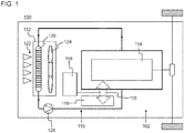
- FIG. 1 shows an embodiment of a generally designated by reference numeral 100 motor vehicle.
- the motor vehicle 100 comprises a drive train 102 and a cooling circuit 110 for the drive train 102.
- the cooling circuit 110 comprises a cooling unit 112 for cooling one along the reinforced line in the direction of the arrow in a schematic block diagram of FIG FIG. 1 circulating coolant.
- the cooling circuit 110 further comprises a drive unit 114 which is in fluid communication with the cooling unit 112 due to the circulating coolant.
- the drive unit 114 while introducing heat into the coolant, provides drive power to the motor vehicle 100 (ie causes a drive torque) or recuperates at least partially drive power from the kinetic energy of the motor vehicle 100 (ie, causes a braking torque).
- the drive unit 114 may include an internal combustion engine, and the provided drive power may be a mechanical power. Alternatively or additionally, the drive unit 114 may include an electric traction energy storage and the drive power may be delivered as high-voltage direct current to a power network of the motor vehicle.
- the cooling circuit 110 further comprises a heat accumulator 116, which can be selectively brought into heat exchange 115 with the coolant and is thermally isolatable from the coolant.
- the cooling circuit 110 further includes a controller 118 which, depending on a driving distance ahead of the motor vehicle 100, brings the heat storage 116 into heat exchange 115 with the coolant or is thermally insulated from the coolant.
- the cooling unit 112 for example in an electric motor vehicle 100 with electric traction energy storage 114 and electric drive train 102, may include a passive radiator 120 swept by wind 122.
- the cooling unit 112 further includes a fan 124 for forced convective heat exchange on the radiator 120 with the surroundings of the motor vehicle 100, for example in a motor vehicle 100 with an internal combustion engine.
- the fan 124 may be driven electrically or hydraulically.
- the fan may be configured to be switched on (eg, by the controller 118) when the temperature of the coolant exceeds a threshold temperature.
- the controller 118 may measure the switched-on heat capacity such that the temperature of the coolant remains below the threshold temperature in the predicted heat input.
- the circulating coolant may include air, water or oil.
- the circulation of the coolant is driven by a coolant pump 126 in the cooling circuit 110.
- a speed of the pump 126 is preferably controlled, for example, by the controller 118.
- the pump may be driven electrically or via a belt.
- the controller 118 includes a data store, or has access to a data store in which topographical map data is stored. Further, the controller 118 determines a location indication or receives a location indication. The location can be determined and / or specified using, for example, kinematic measured variables of the motor vehicle 100 (eg course of the driving speed and / or a steering angle) and / or a locating signal (for example of a global navigation satellite system and / or a mobile radio system).
- kinematic measured variables of the motor vehicle 100 eg course of the driving speed and / or a steering angle
- a locating signal for example of a global navigation satellite system and / or a mobile radio system.
- the controller 118 By linking the topographical map data with the location, the controller 118 (optionally using a speed-dependent air resistance, a rolling resistance and / or a payload of the motor vehicle 100) estimates the heat input of the drive unit 114 to be expected on the preceding route into the coolant.
- a temporal or location-dependent course of the heat input that is to say a time-dependent and / or location-dependent power of the waste heat of the drive unit 114) can be calculated in advance for the route lying ahead.
- the controller 118 causes the effective heat capacity of the coolant to be increased prior to a rise of a mountain, so that in the high-load driving state on the rise by the load-induced heat input of the drive unit 114, the temperature swing of the coolant is reduced that the connection of the fan 124 or an increase in the rotational speed of the pump 126 can be avoided or reduced.
- the amount of heat stored in the heat accumulator 116 is selectively returned to the refrigeration cycle 110 (while maintaining the heat exchange 115 or by restoring the heat exchange 115), for example even if the low-load driving state occurs later (for example a few kilometers later) ,
- Embodiments of the refrigeration cycle 110 may, for example, depending on the technical implementation, drive concept and topography of the route, the energy efficiency (for example, the fuel efficiency in the case of a motor vehicle 100 with internal combustion engine) increase. On the basis of the exact knowledge of the topgraphy of the preceding ones Driving time calculated times for switching on and off the additional heat capacity of the heat accumulator 116.
- a variable heat capacity of the heat accumulator 116 can be switched on.
- the heat storage 116 can be switched on in individual sections (with correspondingly different partial heat capacities).
- a higher efficiency is achieved.
- a larger heat capacity for example, the entire heat capacity of the heat accumulator 116, switched on at larger increases (for example, larger mountains) with greater distances from one another and long gradients and slopes.
- a first implementation of the heat accumulator 116 includes additional volume of coolant that is introduced into the refrigeration cycle 110 to increase its heat capacity or withdrawn to reduce the heat capacity of the refrigeration cycle 110.
- the in-heat exchange is accomplished by adding the additional volume of refrigerant directly into the refrigeration circuit 110 and influences the local temperature of the coolant.
- the heat accumulator 116 comprises a heat exchanger.
- a primary side of the heat exchanger is optionally traversed by the coolant of the cooling circuit 110.
- the switchable heat capacity is provided, which is brought into the heat exchange 115 when flowing through the coolant on the primary side with the coolant.
- the connected heat capacity on the secondary side can be heated or cooled in accordance with the temperature of the coolant.
- the second implementation of the heat accumulator 116 allows the use of a medium on the secondary side of the heat exchanger of the heat accumulator 116, which is different from the coolant of the cooling circuit 110.
- the switchable heat capacity on the secondary side may comprise a solid and / or a medium with changes in its state of matter (for example, between liquid and gaseous) in the relevant temperature range of the coolant.
- the heat accumulator 116 may comprise a thermochemical heat accumulator.
- the medium may be formed on the secondary side of the heat exchanger of the heat accumulator 116 for a reversible endo / exo-thermal reaction.
- the medium may comprise silica gel (for a low temperature range below 100 ° Celsius) or zeolites (for a high temperature range above 100 ° Celsius).
- thermochemical heat storage 116 for example in addition to the switch-on and switch-off times
- a reaction time is determined by the controller 118 in which the enthalpy release is triggered by adsorption (for example by addition of water).
- FIG. 2 shows a schematic block diagram of a first embodiment of the cooling circuit 110.
- the in FIG. 2 The embodiment shown can be combined with any of the above implementation variants.
- Features those of the FIG. 1 are equivalent or functionally equivalent, are provided with matching reference numerals.
- the heat accumulator 116 is connected in parallel with the drive unit 114. By opening a valve 128 in the side branch 115-1, 116, 115-2 of the heat accumulator 116, the controller 118 brings the heat accumulator 116 in heat exchange 115-1, 115-2 with the coolant. The coolant is forced through the heat storage 116 by the pressure drop across the drive unit between ports 115-1 and 115-2.
- the heat accumulator 116 In the open position of the valve 128, the heat accumulator 116 is in heat exchange 115-1, 115-2 with the coolant. In the closed position of the valve 128, the heat accumulator 116 is thermally insulated from the coolant.
- the valve 128 may be a directional control valve (for example, a 2/2-way valve) or a throttle valve (for example, for the freely controllable circulating amount of the coolant via the heat accumulator 116).
- a directional control valve for example, a 2/2-way valve
- a throttle valve for example, for the freely controllable circulating amount of the coolant via the heat accumulator 116.
- FIG. 3 shows a schematic block diagram of a second embodiment of the refrigeration cycle 110.
- the second embodiment is combined with each implementation described above and each embodiment.
- the heat storage 116 is selectively connected in series with the drive unit 114 in the cooling circuit 110.
- a first branch with the heat storage 116 and a second branch parallel to the first branch without heat storage are arranged between the cooling unit 112 and the drive unit 114.
- the second branch can also be called a bypass line.
- the heat exchange feeding port 115-1 is connected to the cooling unit 112, and the heat exchange outgoing port 115-2 is connected to the drive unit 114 via the valve 128.
- the second branch comprises a second valve 130, which allows a bypass path for the coolant past the heat accumulator 116 in its open position.
- the second valve 130 may also be referred to as a bypass valve.
- the heat accumulator 116 is brought into heat exchange with the coolant 115-1, 115-2.
- the valves 128 and 130 are realized by the opposite positions of a switching valve, for example a 3/2-way valve.
- FIG. 4 shows a schematic block diagram of a third embodiment of the refrigeration cycle 110.
- the in FIG. 4 The third exemplary embodiment shown comprises a low-temperature cooling circuit 110-NT and a high-temperature cooling circuit 110-HT with a low-temperature radiator 120-NT and a high-temperature radiator 120-HT, respectively.
- FIG. 4 shown third embodiment, with respect to the low-temperature cooling circuit 110-NT, a development of the parallel circuit of the first embodiment of FIG. 2 and / or with respect to the high-temperature cooling circuit 110-HT, a development of the series connection of the second embodiment of the FIG. 3 be.
- the return of the high temperature refrigeration cycle 110-HT is connected to the inlet of the low temperature refrigeration cycle 110-NT.
- the return of the low-temperature cooling circuit 110-NT flows into the high-temperature cooling circuit 110-HT downstream of the high-temperature radiator 120-HT.
- the pump 126 is disposed in the high-temperature refrigeration cycle 110-HT downstream of the high-temperature radiator 120-HT.
- the different partial circuits 110-NT and 110-HT can each cool different units of the motor vehicle 100.
- the motor vehicle 100 includes an internal combustion engine as a drive unit 114 with at least one exhaust gas turbocharger 132 for compressing and at least one air charging radiator 134 for cooling charge air 136 which is supplied to an air intake tract 138 of the internal combustion engine 114.
- the exhaust gas turbochargers 132 are connected on the turbine side to an exhaust manifold 140 of the internal combustion engine 114.
- the low-temperature cooling circuit 110-NT cools the at least one air-charging radiator 134.
- the high-temperature cooling circuit 110-HT cools the internal combustion engine 114, in particular its liners and oil cooler 142.
- the cooling circuit 110 further cools exhaust gas recirculation (EGR) with a first EGR heat exchanger 144 in the high temperature refrigeration cycle 110-HT and a second EGR heat exchanger 146 in the low temperature refrigeration cycle 110-NT.
- EGR exhaust gas recirculation
- the high-temperature cooling circuit 110-HT cools a heat exchanger 148 of a retarder for wear-free braking of the motor vehicle 100.
- the retarder may be an intarder integrated in the transmission.
- heat for a heater 150 of the motor vehicle 100 can be taken from the high-temperature cooling circuit 110-HT.
- the coolant may predominantly comprise liquid water.
- the high-temperature refrigeration cycle 110-HT can be operated in a range, for example, from 86 ° C to 94 ° C. Changes in the temperature-dependent volume of the coolant are through a surge tank 152, in which liquid and gaseous phase of the refrigerant coexist, balanced via a filling line 154 for the liquid phase.
- a low-pressure accumulator 156 in the high-temperature cooling circuit 110-HT keeps the pressure of the coolant constant or in a range, for example, from 1.0 to 1.5 bar.
- the controller 118 (which for clarity in not FIG. 4 shown) opens to connect the heat accumulator 116 in the low-temperature circuit 110-NT, the valve 128-NT before or at high heat inputs, z. B. a mountain journey. By opening the valve 128-NT, the low-temperature circuit 110-NT is cooled and / or its heat capacity is increased.
- a check valve 129 is arranged at the low-temperature outlet of the heat accumulator 116, in order to avoid a backflow in front of the pump 126.
- the controller 118 opens the valve 128-HT for connecting the heat accumulator 116 in the high-temperature cooling circuit 110-HT.
- the heat storage 116 can be filled again with cold coolant, for. B. at a slight slope.
- the controller 118 opens the valve 128-HT to cool the high temperature refrigeration cycle 110-HT, e.g. B. to avoid a higher Zuschaltgrad the fan 124 and / or the pump 126 due to the temperature of the coolant or reduce.
- the valve 130 serves to throttle the bypass when the heat accumulator 116 is connected to the low-temperature cooling circuit 110-NT.
- the valves 128-NT and 130 are realized by a switching valve.
Landscapes
- Engineering & Computer Science (AREA)
- Chemical & Material Sciences (AREA)
- Combustion & Propulsion (AREA)
- Mechanical Engineering (AREA)
- General Engineering & Computer Science (AREA)
- Electric Propulsion And Braking For Vehicles (AREA)
Abstract
Description
- Die vorliegende Erfindung betrifft einen Kühlkreislauf für einen Antriebsstrang eines Kraftfahrzeugs. Insbesondere sind ein Fahrstrecken-abhängig gesteuerter Kühlkreislauf und ein damit ausgestattetes Kraftfahrzeug beschrieben.
- Das Temperaturmanagement von Kraftfahrzeugen, beispielsweise mit Verbrennungsmotoren, sieht in zunehmendem Maße aktive Thermostaten vor, die beispielsweise elektronisch auf einen Soll-Temperaturwert gesteuert werden. Durch Vorgabe des Soll-Temperaturwerts kann die Kühlmitteltemperatur vorausschauend (auch: prädikativ) gesteuert werden, beispielsweise abhängig von einer vorausliegenden Fahrstrecke (auch: Streckenprofil).
- Das Dokument
DE 10 2013 009 275 A1 beschreibt ein Betriebsverfahren, bei dem der Ölkreislauf einer Antriebsstrangkomponente prädiktiv gesteuert wird abhängig von einem vorausliegenden Streckenprofil. Wird eine höhere Belastung der Antriebsstrangkomponente im Vorausschauhorizont erkannt, erfolgt eine prädiktive Kühlung des Öls bereits vor dem Beginn einer Volllastphase. Dabei ist es möglich, die während der Volllastphase erzeugte Wärme ohne eine Temperaturüberhöhung im Ölkreislauf aufzunehmen. - Zwar kann durch ein solches herkömmliches Betriebsverfahren eine Schwankungsbreite der Öltemperatur verringert werden, beispielsweise zur Optimierung der Viskosität des Öls. Jedoch ist die vorzeitige Kühlung mit einem erhöhten Kraftstoffverbrauch verbunden durch den Betrieb energieaufwendiger Nebenverbraucher. Beispielsweise muss ein Lüfter zugeschaltet werden, der im Nutzfahrzeugbereich eine Leistung von über 10 kW aufnehmen kann, die Drehzahl einer Kühlwasserpumpe muss erhöht werden, und/oder eine vermehrte staudruckgetriebene Kühlluftzufuhr erhöht den Luftwiderstand des Kraftfahrzeugs.
- Zudem ist der Wärmetransport für eine vorzeitige Kühlung, beispielsweise zur Absenkung der Öltemperatur vor dem Anstieg eines Bergs, ineffizienter als die herkömmliche Abgabe von Abwärme in Reaktion auf eine erhöhte Öltemperatur, da die Temperaturdifferenz zwischen Öltemperatur und Umgebungstemperatur bei der vorzeitigen Kühlung geringer ist.
- Somit ist es eine Aufgabe der vorliegenden Erfindung, einen energieeffizienteren Kühlkreislauf für ein Kraftfahrzeug anzugeben. Eine Alternative oder ergänzende Aufgabe ist, eine Technik zum prädiktiven Temperaturmanagement bereitzustellen, bei der ein höherer Zuschaltgrad energieaufwendiger Kühlkreislaufkomponenten reduziert oder vermieden wird.
- Diese Aufgabe oder Aufgaben werden durch einen Kühlkreislauf für einen Antriebsstrang eines Kraftfahrzeugs und ein Kraftfahrzeug gemäß den unabhängigen Ansprüchen gelöst. Vorteilhafte Ausführungen und Anwendungen sind Gegenstand der abhängigen Ansprüche und werden im Folgenden unter teilweiser Bezugnahme auf die Figuren näher erläutert.
- Gemäß einem Aspekt ist ein Kühlkreislauf für einen Antriebsstrang eines Kraftfahrzeugs bereitgestellt. Der Kühlkreislauf umfasst eine Kühleinheit, die dazu ausgebildet ist, ein Kühlmittel zu kühlen; eine Antriebseinheit, die mit der Kühleinheit in Fluidverbindung steht und dazu ausgebildet ist, unter Wärmeeintrag in das Kühlmittel Leistung dem Kraftfahrzeug bereitzustellen oder zu entnehmen; einen Wärmespeicher, der in Wärmeaustausch mit dem Kühlmittel bringbar ist; und eine Steuerung, die dazu ausgebildet ist, den Wärmespeicher abhängig von einer Fahrstrecke des Kraftfahrzeugs in Wärmeaustausch mit dem Kühlmittel zu bringen.
- Die Entnahme der Leistung kann eine Rekuperation (d. h. eine nutzbare Rückgewinnung) umfassen. Beispielsweise kann die Leistung der kinetischen Energie des Fahrzeugs entnommen werden und (zumindest teilweise) gespeichert werden. Alternativ oder ergänzend kann die entnommene Leistung dissipiert (d. h. in Wärme umgesetzt) werden. Beispielsweise kann die entnommene Leistung Teil des Wärmeeintrags sein.
- Die bereitgestellte Leistung kann eine positive Antriebsleistung zur Erzeugung eines Antriebsmoments umfassen. Die entnommene (z. B. rekuperierte und/oder dissipierte) Leistung kann eine negative Antriebsleistung zur Erzeugung eines Bremsmoments umfassen.
- Die Antriebseinheit kann eine Komponente des Antriebsstrangs des Kraftfahrzeugs sein. Beispielsweise kann die Antriebseinheit die Antriebsleistung (auch: Traktionsleistung) für den Antriebsstrang bereitstellen. Die bereitgestellte Antriebsleistung kann eine elektrische Leistung oder eine mechanische Leistung umfassen. Der Wärmeeintrag kann eine Abwärme der Antriebseinheit bei der Abgabe der Antriebsleistung oder im Fall der Rekuperation sein.
- Die Steuerung des Wärmeaustauschs mit dem Wärmespeicher kann ferner von anderen Einflussfaktoren des Kühlkreislaufs abhängig sein. Die Steuerung des Wärmeaustauschs kann von jedem prognostizierten Wärmeeintrag in das Kühlmittel und/oder jeder prognostizierten Wärmeabgabe abhängen.
- Die Steuerung des Wärmeaustauschs kann von einer vorausliegenden Fahrstrecke und, optional, von einer zurückliegenden Fahrstrecke abhängen. Beispielsweise kann die Steuerung den Wärmeaustausch beginnen, wenn die vorausliegende Fahrstrecke einen hochlastigen (auch: lastreichen) Abschnitt umfasst. Alternativ oder ergänzend kann die Steuerung den Wärmeaustausch beenden, wenn die zurückliegende Fahrstrecke einen niederlastigen (auch: lastarmen) Abschnitt umfasst. Beispielsweise stehen der Wärmespeicher und das Kühlmittel während eines Berganstiegs und während eines anschließenden Gefälles in Wärmeaustausch.
- Der Beginn oder die Herstellung des Wärmeaustauschs zwischen Wärmespeicher und Kühlmittel kann auch als Zuschalten bezeichnet werden. Ein Ende des Wärmeaustauschs oder eine thermische Trennung (auch: Isolation) des Wärmespeichers vom Kühlmittel im Kühlkreislauf kann auch als Abschalten bezeichnet werden.
- Der nach Maßgabe der Steuerung in Wärmeaustausch mit dem Kühlmittel bringbare Wärmespeicher kann auch als zuschaltbare bzw. abschaltbare Wärmekapazität bezeichnet werden. Die zuschaltbare bzw. abschaltbare Wärmekapazität kann sich auf eine vergrößerte bzw. verkleinerte thermische Trägheit des Kühlkreislaufs beziehen. Dabei ist ein funktionaler Zusammenhang zwischen der im Wärmespeicher gespeicherten Wärmemenge und der Temperatur des Kühlmittels nicht notwendigerweise linear.
- Zumindest in Ausführungsbeispielen kann ein Temperaturverlauf des Kühlmittels geglättet und/oder eine Varianz der Temperatur des Kühlmittels verringert werden, ohne zusätzlichen Leistungsbedarf im Kühlkreislauf. Durch das temporäre Zuschalten des Wärmespeichers kann ein Anstieg der Temperatur des Kühlmittels, beispielsweise an einem Berganstieg der Fahrstrecke, ohne erhöhten Energieaufwand im Kühlkreislauf, begrenzt oder verringert werden. So können durch das Zuschalten vor einem hochlastigen Fahrzustand beispielsweise Spitzentemperaturen des Kühlmittels und der zu kühlenden Antriebseinheit niedriger ausfallen als ohne das Zuschalten. Der Temperaturanstieg kann so begrenzt oder verringert werden, dass der Betrieb oder eine Leistungserhöhung eines Nebenverbrauchers des Kühlkreislaufs im lastreichen Abschnitt unterbleibt.
- Die Kühleinheit kann einen Kühler zur Abgabe von Wärme vom Kühlmittel an Umgebungsluft umfassen. Die Kühleinheit kann eine aktive Kühleinheit (beispielsweise mit einem Lüfter) oder eine passive Kühleinheit (beispielsweise unter Ausnutzung des Fahrtwinds und/oder Konvektion) sein. Die Kühleinheit kann ferner eine Pumpe zur Zirkulation des Kühlmittels im Kühlkreislauf zwischen Antriebseinheit und Kühler umfassen. Das Kühlmittel kann beispielsweise Wasser oder Öl umfassen.
- Das Kraftfahrzeug kann ein Personenkraftwagen (PKW) oder ein Nutzfahrzeug, beispielsweise ein Lastkraftwagen (insbesondere eine Sattelzugmaschine) oder ein Bus sein. Die Antriebseinheit kann eine Brennkraftmaschine, einen elektrischen Traktionsenergiespeicher, eine elektrische Maschine (E-Maschine) und/oder einen Stromrichter (beispielsweise einen Wechselrichter und/oder Gleichrichter) umfassen. Insbesondere kann die Antriebseinheit einen Hybridantrieb mit einer Brennkraftmaschine und einer E-Maschine umfassen.
- Die Antriebseinheit kann einen wärmeerzeugenden Traktionsenergiespeicher (z. B. Akkumulatoren als elektrische Traktionsenergiespeicher bei Elektroantrieben) umfassen. Der Traktionsenergiespeicher kann (beispielsweise beim Antreiben oder Rekuperieren) eine Quelle des Wärmeeintrags in das Kühlmittel sein. Die Funktion des Wärmespeichers und/oder der Steuerung kann analog zum hierin beschriebenen Fall einer Brennkraftmaschine erfolgen.
- Der Wärmeeintrag kann Abwärme beim Erzeugen eines Antriebsmoments mittels der Antriebseinheit und/oder Abwärme beim Erzeugen eines Bremsmoments mittels der Antriebseinheit umfassen. Die Antriebseinheit kann eine Dauerbremse (beispielsweise einen Retarder) umfassen, deren Abwärme beim Erzeugen des Bremsmoments in das Kühlmittel eingetragen wird.
- Alternativ oder ergänzend kann die E-Maschine den elektrischen Traktionsenergiespeicher aufladen beim Erzeugen des Bremsmoments, wobei die in das Kühlmittel eingetragene Abwärme durch die E-Maschine, den Stromrichter und/oder den elektrischen Traktionsenergiespeicher verursacht wird.
- Die Steuerung kann dazu ausgebildet sein, den Wärmespeicher wahlweise mit dem Kühlmittel in Wärmeaustausch zu bringen oder den Wärmespeicher vom Kühlmittel zu isolieren. Optional kann die Steuerung einen Grad des Wärmeaustauschs (d. h. eine Leistung des Wärmetransports) steuern. Beispielsweise kann eine Wärmeleitung oder eine Konvektion des Wärmeaustauschs zwischen dem Wärmespeicher und dem Kühlmittel gesteuert werden.
- Durch den Wärmeaustausch kann eine Wärmekapazität des Kühlkreislaufs (beispielsweise eine effektive Wärmekapazität des Kühlmittels) vergrößert werden. Durch die Isolation kann die Wärmekapazität verringert werden. Alternativ oder ergänzend zum Grad des Wärmeaustauschs kann die Steuerung die zugeschaltete und/oder abgeschaltete Wärmekapazität des Wärmespeichers in mehreren Stufen oder stufenlos steuern.
- Die Antriebseinheit kann Kanäle umfassen, die zur Aufnahme des Kühlmittels ausgebildet sind. Beispielsweise können die Kanäle in einem Motorblock oder einer Ölwanne der Brennkraftmaschine und/oder zwischen elektrochemischen Zellen des Traktionsenergiespeichers verlaufen. Die Kanäle können mit der Kühleinheit in Fluidverbindung stehen.
- Das Kühlmittel kann zwischen der Kühleinheit und der Antriebseinheit zirkulieren, beispielsweise durch die Kanäle. Bezüglich der Zirkulation kann der Wärmespeicher mit der Antriebseinheit in Reihe geschaltet sein, wenn der Wärmespeicher mit dem Kühlmittel in Wärmeaustausch steht. Beispielsweise kann der Wärmespeicher (bezüglich einer Strömungsrichtung des zirkulierenden Kühlmittels) stromabwärts der Kühleinheit und/oder stromaufwärts der Antriebseinheit angeordnet sein, oder der Wärmespeicher kann in Zirkulationsrichtung nach der Antriebseinheit angeordnet sein. Der Wärmespeicher kann vom Kühlmittel thermisch isoliert werden, indem das Kühlmittel am Wärmespeicher vorbei geleitet wird, beispielsweise durch eine Bypass-Leitung.
- Alternativ oder ergänzend kann der Wärmespeicher bezüglich der Zirkulation parallel geschaltet sein, wenn der Wärmespeicher mit dem Kühlmittel in Wärmeaustausch steht. Beispielsweise kann der Wärmespeicher parallel zur Antriebseinheit geschaltet sein. Ein Druckabfall an der Antriebseinheit kann eine Durchströmung des Wärmespeichers mit dem Kühlmittel antreiben.
- Der Wärmespeicher kann weiteres Kühlmittel umfassen. Das weitere Kühlmittel kann mit dem Kühlmittel im Kühlkreislauf durch Zumischen in Wärmeaustausch gebracht werden.
- Beispielsweise kann der Wärmeaustausch durch Zuschalten eines Kühlmittelreservoirs bewirkt werden, welches das weitere Kühlmittel enthält. Das zugeschaltete Kühlmittelreservoir kann vom zirkulierenden Kühlmittel durchströmt werden oder mit dem zirkulierenden Kühlmittel in konvektiver Fluidverbindung stehen.
- Alternativ oder ergänzend kann die Steuerung eine Entnahme von Kühlmittel aus dem Kühlkreislauf bewirken. Durch die Entnahme von Kühlmittel aus dem Kühlkreislauf in den Wärmespeicher (beispielsweise durch Aussonderung von Kühlmittel aus dem zirkulierenden Teil des Kühlkreislaufs zu einem im Wärmespeicher stehenden Fluid), kann das entnommene Kühlmittel vom Kühlkreislauf (insbesondere von der Antriebseinheit und/oder der Kühleinheit) thermisch isoliert werden.
- Der Wärmespeicher kann eine Rohrleitung umfassen. Die Rohrleitung kann das weitere Kühlmittel aufnehmen (insbesondere beim Zuschalten vom Kühlkreislauf entnehmen) oder enthalten (insbesondere beim Abschalten vom Kühlkreislauf aussondern). Eine Länge und/oder ein Durchmesser der Rohrleitung kann größer sein als bei anderen Leitungen (beispielsweise Anschlussleitungen) des Kühlkreislaufs. Für eine kompakte Bauform des Wärmespeichers kann die Rohrleitung mäanderförmig verlaufen, beispielsweise als Kanäle in einem integral-einstückigen Bauteil.
- Beispielsweise kann der Wärmeaustausch durch Zuschalten der Rohrleitung in den Kühlkreislauf bewirkt werden. Indem das zirkulierende Kühlmittel das in der Rohrleitung vorgehaltene weitere Kühlmittel verdrängt (beispielsweise ohne wesentliche Durchmischung in der Rohrleitung) kann mit geringer thermischer Trägheit der Wärmespeicher zugeschaltet werden. Beispielsweise kann sich so die Temperatur des weiteren Kühlmittels unmittelbar bei der Zuschaltung auf die Temperatur des zirkulierenden Kühlmittels auswirken.
- Der Wärmeaustausch mit dem Wärmespeicher kann eine Wärmekapazität erhöhen. Die Steuerung kann die Erhöhung der Wärmekapazität durch ein veränderbares Volumen des Wärmespeichers steuern.
- Beispielsweise umfasst der Wärmespeicher einen Zylinder der an einem ersten Ende mit dem Kühlkreislauf zum Wärmeaustausch in Fluidverbindung bringbar ist. An einem dem ersten Ende gegenüberliegenden zweiten Ende ist der Zylinder von einem längsbeweglichen Kolben verschlossen. Durch die Längsbewegung des Kolbens im Zylinder (beispielsweise hin zum ersten Ende oder weg vom ersten Ende) kann das Volumen des Wärmespeichers verkleinert bzw. vergrößert werden.
- Alternativ oder ergänzend kann eine Erhöhung der Wärmekapazität beim Zuschalten der Rohrleitung durch die Länge der zugeschalteten Rohrleitung gesteuert werden. Beispielsweise kann die Rohrleitung mehrere Abzweigungen aufweisen, die jeweils als Einlass und/oder Auslass mit dem Kühlkreislauf in Fluidverbindung bringbar sind. Durch die Länge (beispielsweise vom Einlass und/oder bis zum Auslass) der zugeschalteten Rohrleitung kann die Erhöhung der Wärmekapazität (d. h. die zugeschaltete Wärmekapazität) stufenweise gesteuert werden.
- Die Steuerung kann ferner dazu ausgebildet sein, auf Grundlage der vorausliegenden Fahrstrecke einen zukünftigen Wärmeeintrag oder einen zeitlichen Verlauf des zukünftigen Wärmeeintrags zu berechnen. Abhängig von dem berechneten zukünftigen Wärmeeintrag (beispielsweise im Vergleich zu einer Wärmeabgabe der Kühleinrichtung ohne zusätzlichen leistungsaufwand) kann die Steuerung die Wärmekapazität durch Zuschalten erhöhen oder durch Abschalten reduzieren. Ferner kann das Zuschalten und/oder das Abschalten von einer Ist-Temperatur des Kühlmittels und/oder einer Ist-Temperatur des Wärmespeichers abhängen. Beispielsweise kann das Abschalten im lastarmen Bereich erst erfolgen, wenn die Ist-Temperatur des Wärmespeichers einen Schwellwert unterschritten hat.
- Die Größe der zugeschalteten Wärmekapazität kann von einem vorausberechneten Nettowärmeeintrag in einem zusammenhängenden Zeitraum abhängen. Beispielsweise wird der Nettowärmeeintrag als zeitliches Integral der positiven Differenz zwischen Abwärmeleistung der Antriebseinheit und Kühlleistung der Kühleinheit vorausberechnet. Der zusammenhängende Zeitraum kann durch die Positivität der Differenz zwischen Abwärmeleistung und Kühlleistung bestimmt sein. Dabei kann die Kühlleistung von Randbedingungen des Kraftfahrzeugs, beispielsweise von einer Umgebungstemperatur des Kraftfahrzeugs, einer Fahrgeschwindigkeit des Kraftfahrzeugs und/oder einer Kühlmittelpumpenleistung abhängen.
- Der Wärmespeicher kann über einen Wärmetauscher (beispielsweise primärseitig) mit dem Kühlmittel in Wärmeaustausch gebracht werden. Die zuschaltbare Wärmekapazität kann (beispielsweise sekundärseitig) durch ein Medium bereitgestellt werden.
- Der Wärmespeicher kann für einen Phasenübergang ausgebildet sein. Beispielsweise kann das sekundärseitige Medium dazu ausgebildet sein, im Arbeitsbereich der Kühlmitteltemperatur seinen Aggregatszustand zu ändern. Der Wärmeaustausch kann latente Wärme des Phasenübergangs umfassen.
- Die Steuerung kann vor einem lastreichen Abschnitt der Fahrstrecke den Wärmespeicher in Wärmeaustausch mit dem Kühlmittel bringen zur Aufnahme zumindest eines Teils des Wärmeeintrags im lastreichen Abschnitt. Die Steuerung kann den lastreichen Abschnitt der Fahrstrecke durch Ortung des Kraftfahrzeugs, Kartendaten (beispielsweise Daten zur Fahrbahnneigung oder Fahrbahnhöhe) und/oder Erfassung einer Beschilderung bestimmen. Der lastreiche Abschnitt kann einen Anstieg der Längsneigung einer Fahrbahn und/oder eine Erhöhung einer Höchstgeschwindigkeit umfassen. Alternativ oder ergänzend kann die Steuerung aufgrund eines Zuladeorts der Fahrstrecke einen Beginn des lastreichen Abschnitts bestimmen. Der Zuladeort kann ein Beladeort eines Lastkraftwagens oder eines Baustellenfahrzeugs oder eine Einstiegsstelle eines Busses sein.
- Die Steuerung kann vor einem lastarmen Abschnitt der Fahrstrecke den Wärmespeicher in Wärmeaustausch mit dem Kühlmittel bringen oder halten zur Abgabe von im Wärmespeicher gespeicherten Wärme während des lastarmen Abschnitts. Die Steuerung kann den lastarmen Abschnitt der Fahrstrecke durch die Ortung, die Kartendaten und/oder die Beschilderungserkennung bestimmen. Der lastarme Abschnitt kann eine ebene Fahrbahn, eine abfallende Fahrbahn und/oder eine Reduzierung der Höchstgeschwindigkeit umfassen. Alternativ oder ergänzend kann die Steuerung aufgrund eines Entladeorts der Fahrstrecke einen Beginn des lastarmen Abschnitts bestimmen. Der Entladeort kann ein Abladeort des Lastkraftwagens oder des Baustellenfahrzeugs oder eine Ausstiegsstelle des Busses sein.
- Gemäß einem weiteren Aspekt ist ein Kraftfahrzeug, insbesondere ein PKW oder ein Nutzfahrzeug, bereitgestellt. Das Kraftfahrzeug umfasst einen Antriebsstrang mit einer Antriebseinheit und einen die Antriebseinheit kühlenden Kühlkreislauf gemäß einer Ausgestaltung des vorstehenden Aspekts.
- Weitere Merkmale und Vorteile der Erfindung werden im Folgenden unter Bezugnahme auf die beigefügten Zeichnungen beschrieben. Es zeigen:
- Figur 1
- ein schematisches Blockschaltbild eines Ausführungsbeispiels eines Kraftfahrzeugs mit einem Kühlkreislauf für einen Antriebsstrang des Kraftfahrzeugs;
- Figur 2
- ein schematisches Blockschaltbild eines ersten Ausführungsbeispiels des Kühlkreislaufs;
- Figur 3
- ein schematisches Blockschaltbild eines zweiten Ausführungsbeispiels des Kühlkreislaufs; und
- Figur 4
- eine Weiterbildung des ersten und zweiten Ausführungsbeispiels für ein Kraftfahrzeug mit Brennkraftmaschine.
-
Figur 1 zeigt ein Ausführungsbeispiel eines allgemein mit Bezugszeichen 100 bezeichneten Kraftfahrzeugs. Das Kraftfahrzeug 100 umfasst einen Antriebsstrang 102 und einen Kühlkreislauf 110 für den Antriebsstrang 102. - Der Kühlkreislauf 110 umfasst eine Kühleinheit 112 zur Kühlung eines entlang der verstärkten Linie in Pfeilrichtung im schematischen Blockschaltbild der
Figur 1 zirkulierenden Kühlmittels. Der Kühlkreislauf 110 umfasst ferner eine Antriebseinheit 114, die aufgrund des zirkulierenden Kühlmittels in Fluidverbindung mit der Kühleinheit 112 steht. Die Antriebseinheit 114 stellt unter Wärmeeintrag in das Kühlmittel Antriebsleistung für das Kraftfahrzeug 100 bereit (d. h. bewirkt ein Antriebsmoment) oder rekuperiert aus der kinetischen Energie des Kraftfahrzeugs 100 zumindest teilweise Antriebsleistung (d. h. bewirkt ein Bremsmoment). - Die Antriebseinheit 114 kann eine Brennkraftmaschine umfassen, und die bereitgestellte Antriebsleistung kann eine mechanische Leistung sein. Alternativ oder ergänzend kann die Antriebseinheit 114 einen elektrischen Traktionsenergiespeicher umfassen und die Antriebsleistung kann als Hochvolt-Gleichstrom an ein Leistungsnetz des Kraftfahrzeugs abgegeben werden.
- Der Kühlkreislauf 110 umfasst ferner einen Wärmespeicher 116, der wahlweise in Wärmeaustausch 115 mit dem Kühlmittel bringbar ist und vom Kühlmittel thermisch isolierbar ist. Der Kühlkreislauf 110 umfasst ferner eine Steuerung 118, die abhängig von einer vorausliegenden Fahrstrecke des Kraftfahrzeugs 100 den Wärmespeicher 116 in Wärmeaustausch 115 mit dem Kühlmittel bringt oder vom Kühlmittel thermisch isoliert wird.
- Die Kühleinheit 112 kann, beispielsweise bei einem Elektro-Kraftfahrzeug 100 mit elektrischem Traktionsenergiespeicher 114 und elektrischem Antriebsstrang 102, einen passiven Kühler 120 umfassen, der von Fahrtwind 122 überstrichen wird.
- Optional umfasst die Kühleinheit 112 ferner einen Lüfter 124 zum getriebenen konvektiven Wärmeaustausch am Kühler 120 mit der Umgebung des Kraftfahrzeugs 100, beispielsweise bei einem Kraftfahrzeug 100 mit Brennkraftmaschine. Der Lüfter 124 kann elektrisch oder hydraulisch angetrieben sein. Der Lüfter kann dazu ausgebildet sein (beispielsweise von der Steuerung 118) zugeschaltet zu werden, wenn die Temperatur des Kühlmittels eine Grenztemperatur überschreitet. Die Steuerung 118 kann die zugeschaltete Wärmekapazität so bemessen, dass bei dem vorausberechneten Wärmeeintrag die Temperatur des Kühlmittels unter der Grenztemperatur bleibt.
- Das zirkulierende Kühlmittel kann Luft, Wasser oder Öl umfassen. Vorzugsweise wird die Zirkulation des Kühlmittels durch eine Kühlmittelpumpe 126 im Kühlkreislauf 110 getrieben. Eine Drehzahl der Pumpe 126 ist vorzugsweise geregelt, beispielsweise von der Steuerung 118. Die Pumpe kann elektrisch oder über einen Riemen angetrieben sein.
- Die Steuerung 118 umfasst einen Datenspeicher, oder hat Zugriff auf einen Datenspeicher, in dem topographische Kartendaten abgespeichert sind. Ferner bestimmt die Steuerung 118 eine Ortungsangabe oder erhält eine Ortungsangabe. Die Ortsangabe kann beispielsweise unter Verwendung kinematischer Messgrößen des Kraftfahrzeugs 100 (z. B. Verlauf der Fahrgeschwindigkeit und/oder eines Lenkwinkels) und/oder eines Ortungssignals (beispielsweise eines globalen Navigationssattelitensystems und/oder eines Mobilfunksystems) bestimmt und/oder präzisiert werden.
- Durch Verknüpfung der topgraphischen Kartendaten mit der Ortsangabe schätzt die Steuerung 118 (optional unter Verwendung eines geschwindigkeitsabhängigen Luftwiderstands, eines Rollwiderstand und/oder einer Zuladung des Kraftfahrzeugs 100) den auf der vorausliegenden Fahrstrecke zu erwartenden Wärmeeintrag der Antriebseinheit 114 in das Kühlmittel. Insbesondere kann ein zeitlicher oder ortsabhängiger Verlauf des Wärmeeintrags (d. h. eine zeit- und/oder ortsabhängige Leistung der Abwärme der Antriebseinheit 114) für die vorausliegende Fahrstrecke vorausberechnet werden.
- Beispielsweise bewirkt die Steuerung 118 durch den Wärmeaustausch 115 mit dem Wärmespeicher 116, dass die effektive Wärmekapazität des Kühlmittels vor einem Anstieg eines Bergs vergrößert wird, so dass im hochlastigen Fahrzustand am Berganstieg durch den lastbedingten Wärmeeintrag der Antriebseinheit 114 der Temperaturhub des Kühlmittels verringert wird, so dass die Zuschaltung des Lüfters 124 oder eine Erhöhung der Drehzahl der Pumpe 126 vermieden oder reduziert werden kann.
- Indiziert die vorausliegende Fahrstrecke einen schwachlastigen Fahrzustand, wird (unter Beibehaltung des Wärmeaustauschs 115 oder durch Wiederherstellung des Wärmeaustauschs 115) die im Wärmespeicher 116 gespeicherte Wärmemenge gezielt wieder dem Kühlkreislauf 110 zugeführt, beispielsweise auch wenn der schwachlastige Fahrzustand erst später (beispielsweise einige Kilometer später) eintritt.
- Ausführungsbeispiele des Kühlkreislaufs 110 können, beispielsweise je nach technischer Umsetzung, Antriebskonzept und Topographie der Fahrstrecke, die Energieeffizienz (beispielsweise die Kraftstoffeffizienz im Fall eines Kraftfahrzeugs 100 mit Brennkraftmaschine) steigern. Dazu werden auf Grundlage der genauen Kenntnis der Topgraphie der vorausliegenden Fahrstrecke Zeitpunkte zum Zuschalten und Abschalten der zusätzlichen Wärmekapazität des Wärmespeichers 116 berechnet.
- Alternativ oder ergänzend zu einer bipolaren oder regelbaren Zu- oder Abschaltung der zusätzlichen Wärmekapazität des Wärmespeichers 116 (durch Herstellung des Wärmeaustauschs 115 bzw. Trennung des Wärmeaustauschs 115) kann eine variable Wärmekapazität des Wärmespeichers 116 zugeschalten werden. Beispielsweise kann der Wärmespeicher 116 in einzelnen Anschnitten (mit entsprechend unterschiedlichen Teilwärmekapazitäten) zugeschaltet werden.
- Abhängig von der Topographie der vorausliegenden Fahrstrecke wird dadurch eine höhere Effizienz erzielt. Bei kleineren Anstiegen (beispielsweise kleineren Bergen) mit geringen Abständen zueinander und kurzen Steigungen und Gefällen wird nur ein Teil der Wärmekapazität des Wärmespeichers 116 zugeschaltet, da durch kürzere Fahrzeiten in Gefällen weniger Zeit zum Herunterkühlen des Wärmespeichers 116 zur Verfügung steht und durch kürzere Fahrzeiten in der Steigung die geringere Wärmekapazität zur Begrenzung des Temperaturhubs des Kühlmittels ausreicht. Alternativ oder ergänzend wird bei größeren Anstiegen (beispielsweise größeren Bergen) mit größeren Abständen zueinander und langen Steigungen und Gefällen eine größere Wärmekapazität, beispielsweise die gesamte Wärmekapazität des Wärmespeichers 116, zugeschaltet.
- Eine erste Implementierung des Wärmespeichers 116 umfasst zusätzliches Kühlmittelvolumen, das in den Kühlkreislauf 110 eingebracht wird zur Erhöhung dessen Wärmekapazität oder entnommen wird zur Reduzierung der Wärmekapazität des Kühlkreislaufs 110. Das In-Wärmeaustausch-Bringen erfolgt durch Zumischen des zusätzlichen Kühlmittelvolumens direkt in den Kühlkreislauf 110 und beeinflusst die dortige Temperatur des Kühlmittels.
- In einer zweiten Implementierung, die mit der ersten kombinierbar ist, umfasst der Wärmespeicher 116 einen Wärmetauscher. Eine Primärseite des Wärmetauschers wird wahlweise vom Kühlmittel des Kühlkreislaufs 110 durchströmt. Auf der Sekundärseite des Wärmetauschers ist die zuschaltbare Wärmekapazität vorgesehen, die beim Durchströmen des Kühlmittels auf der Primärseite mit dem Kühlmittel in Wärmeaustausch 115 gebracht ist. Dadurch kann die zugeschaltete Wärmekapazität auf der Sekundärseite entsprechend der Temperatur des Kühlmittels aufgeheizt oder abgekühlt werden. Durch eine frei regelbare Umlaufmenge des Kühlmittels über den Wärmetauscher des Wärmespeichers 116 kann auf der Sekundärseite des Wärmetauschers die dort befindliche Wärmekapazität in regelbarem Umfang mit dem Kühlmittel in Wärmeaustausch 115 gebracht werden.
- Die zweite Implementierung des Wärmespeichers 116 ermöglicht den Einsatz eines Mediums auf der Sekundärseite des Wärmetauschers des Wärmespeichers 116, das vom Kühlmittel des Kühlkreislaufs 110 verschieden ist. Beispielsweise kann die zuschaltbare Wärmekapazität auf der Sekundärseite einen Festkörper und/oder ein Medium mit Änderungen seines Aggregatzustands (beispielsweise zwischen flüssig und gasförmig) im betreffenden Temperaturbereich des Kühlmittels umfassen. Durch die Freisetzung einer Enthalpie der Änderung des Aggregatzustands (bei Absenkung der Temperatur des Kühlmittels im lastarmen Fahrzustand des Kraftfahrzeugs 100) bzw. die Entnahme von Wärmemenge aus dem Kühlkreislauf 100 (bei hohen Temperaturen des Kühlmittels im lastreichen Fahrzustand des Kraftfahrzeugs 100) kann ein kompakter Wärmespeicher 116 mit hoher zuschaltbarer Wärmekapazität realisiert sein.
- Alternativ oder ergänzend kann der Wärmespeicher 116 einen thermochemischen Wärmespeicher umfassen. Beispielsweise kann das Medium auf der Sekundärseite des Wärmetauschers des Wärmespeichers 116 zu einer reversiblen endo/exo-thermischen Reaktion ausgebildet sein. Beispielsweise kann das Medium Silikagel (für einen niedrigen Temperaturbereich unter 100° Celsius) oder Zeolithe (für einen hohen Temperaturbereich über 100° Celsius) umfassen. Optional wird beim Einsatz thermochemischer Wärmespeicher 116 (beispielsweise zusätzlich zu den Zu- und Abschaltzeitpunkten) ein Reaktionszeitpunkt von der Steuerung 118 bestimmt, bei dem durch Adsorption (beispielsweise durch Wasserzugabe) die Enthalpiefreisetzung ausgelöst wird.
-
Figur 2 zeigt ein schematisches Blockschaltbild eines ersten Ausführungsbeispiels des Kühlkreislaufs 110. Das inFigur 2 gezeigte Ausführungsbeispiel ist mit jeder der vorstehenden Implementierungsvarianten kombinierbar. Merkmale die jenen derFigur 1 entsprechen oder funktional äquivalent sind, sind mit übereinstimmenden Bezugszeichen versehen. - Der Wärmespeicher 116 ist parallel zur Antriebseinheit 114 geschaltet. Durch Öffnen eines Ventils 128 im Seitenzweig 115-1, 116, 115-2 des Wärmespeichers 116 bringt die Steuerung 118 den Wärmespeicher 116 in Wärmeaustausch 115-1, 115-2 mit dem Kühlmittel. Das Kühlmittel wird durch den Druckabfall an der Antriebseinheit zwischen den Anschlüssen 115-1 und 115-2 durch den Wärmespeicher 116 getrieben.
- In der Offenstellung des Ventils 128 steht der Wärmespeicher 116 in Wärmeaustausch 115-1, 115-2 mit dem Kühlmittel. In der Schließstellung des Ventils 128 ist der Wärmespeicher 116 vom Kühlmittel thermisch isoliert.
- Das Ventil 128 kann ein Wegeventil (beispielsweise ein 2/2-Wegeventil) oder ein Drosselventil (beispielsweise für die frei regelbare Umlaufmenge des Kühlmittels über den Wärmespeicher 116) sein.
-
Figur 3 zeigt ein schematisches Blockschaltbild eines zweiten Ausführungsbeispiels des Kühlkreislaufs 110. Das zweite Ausführungsbeispiel ist mit jeder vorstehend beschriebenen Implementierung und jedem Ausführungsbeispiel kombinierbar. Im inFigur 3 gezeigten zweiten Ausführungsbeispiel ist der Wärmespeicher 116 in Reihe mit der Antriebseinheit 114 im Kühlkreislauf 110 wahlweise zugeschaltet. - Stromabwärts der Kühleinheit 112 sind zwischen der Kühleinheit 112 und der Antriebseinheit 114 ein erster Zweig mit dem Wärmespeicher 116 und ein zum ersten Zweig paralleler zweiter Zweig ohne Wärmespeicher angeordnet. Der zweite Zweig kann auch als Bypass-Leitung bezeichnet werden.
- Im ersten Zweig ist der zuführende Anschluss des Wärmeaustauschs 115-1 mit der Kühleinheit 112 verbunden und der ausströmende Anschluss des Wärmeaustauschs 115-2 ist über das Ventil 128 mit der Antriebseinheit 114 verbunden. Der zweite Zweig umfasst ein zweites Ventil 130, das in seiner Offenstellung einen Umgehungsweg für das Kühlmittel am Wärmespeicher 116 vorbei ermöglicht. Das zweite Ventil 130 kann auch als Bypass-Ventil bezeichnet werden.
- In der Schließstellung des zweiten Ventils 130 und bei Offenstellung des Ventils 128 ist der Wärmespeicher 116 mit dem Kühlmittel in Wärmeaustausch 115-1, 115-2 gebracht. Optional sind die Ventile 128 und 130 durch die entgegengesetzten Stellungen eines Umschaltventils realisiert, beispielsweise eines 3/2-Wegeventils.
-
Figur 4 zeigt ein schematisches Blockschaltbild eines dritten Ausführungsbeispiels des Kühlkreislaufs 110. Das inFigur 4 gezeigte dritte Ausführungsbeispiel umfasst einen Niedertemperatur-Kühlkreislauf 110-NT und einen Hochtemperatur-Kühlkreislauf 110-HT mit einem Niedertemperatur-Kühler 120-NT bzw. einem Hochtemperatur-Kühler 120-HT. - Das in
Figur 4 gezeigte dritte Ausführungsbeispiel kann bezüglich des Niedertemperatur-Kühlkreislaufs 110-NT eine Weiterbildung der Parallelschaltung des ersten Ausführungsbeispiels derFigur 2 und/oder bezüglich des Hochtemperatur-Kühlkreislaufs 110-HT eine Weiterbildung der Reihenschaltung des zweiten Ausführungsbeispiels derFigur 3 sein. - Der Rücklauf des Hochtemperatur-Kühlkreislaufs 110-HT ist mit dem Einlass des Niedertemperatur-Kühlkreislaufs 110-NT verbunden. Der Rücklauf des Niedertemperatur-Kühlkreislaufs 110-NT mündet stromabwärts des Hochtemperatur-Kühlers 120-HT in den Hochtemperatur-Kühlkreislauf 110-HT. Die Pumpe 126 ist im Hochtemperatur-Kühlkreislauf 110-HT stromabwärts des Hochtemperatur-Kühlers 120-HT angeordnet.
- Die unterschiedlichen Teilkreisläufe 110-NT und 110-HT können jeweils unterschiedliche Aggregate des Kraftfahrzeugs 100 kühlen.
- Beispielsweise umfasst das Kraftfahrzeug 100 eine Brennkraftmaschine als Antriebseinheit 114 mit mindestens einem Abgasturbolader 132 zum Verdichten und mindestens einem Luftladekühler 134 zum Kühlen von Ladeluft 136, die einem Luftansaugtrakt 138 der Brennkraftmaschine 114 zugeführt wird. Die Abgasturbolader 132 sind turbinenseitig mit einem Abgaskrümmer 140 der Brennkraftmaschine 114 verbunden.
- Der Niedertemperatur-Kühlkreislauf 110-NT kühlt den mindestens einen Luftladekühler 134. Der Hochtemperatur-Kühlkreislauf 110-HT kühlt die Brennkraftmaschine 114, insbesondere dessen Laufbuchsen und Ölkühler 142.
- Optional kühlt der Kühlkreislauf 110 ferner eine Abgasrückführung (AGR) mit einem ersten AGR-Wärmetauscher 144 im Hochtemperatur-Kühlkreislauf 110-HT und einem zweiten AGR-Wärmetauscher 146 im Niedertemperatur-Kühlkreislauf 110-NT.
- Alternativ oder ergänzend kühlt der Hochtemperatur-Kühlkreislauf 110-HT einen Wärmetauscher 148 eines Retarders zum verschleißfreien Bremsen des Kraftfahrzeugs 100. Der Retarder kann ein im Getriebe integrierter Intarder sein.
- Ferner kann dem Hochtemperatur-Kühlkreislauf 110-HT Wärme für eine Heizung 150 des Kraftfahrzeugs 100 entnommen werden.
- Das Kühlmittel kann überwiegend flüssiges Wasser umfassen. Der Hochtemperatur-Kühlkreislauf 110-HT kann in einem Bereich beispielsweise von 86 °C bis 94 °C betrieben werden. Änderungen des temperaturabhängigen Volumens des Kühlmittels werden durch einen Ausgleichsbehälter 152, in dem flüssige und gasförmige Phase des Kühlmittels koexistieren, über eine Füllleitung 154 für die flüssige Phase ausgeglichen. Ein Niederdruckspeicher 156 im Hochtemperatur-Kühlkreislauf 110-HT hält den Druck des Kühlmittels konstant oder in einem Bereich beispielsweise von 1,0 bis 1,5 bar.
- Die Steuerung 118 (welche zur besseren Übersichtlichkeit nicht in
Figur 4 gezeigt ist) öffnet zur Zuschaltung des Wärmespeichers 116 in den Niedertemperatur-Kreislauf 110-NT das Ventil 128-NT vor oder bei hohen Wärmeeinträgen, z. B. einer Bergfahrt. Durch das Öffnen des Ventils 128-NT wird der Niedertemperatur-Kreislauf 110-NT gekühlt und/oder dessen Wärmekapazität erhöht. Optional ist am Niedertemperatur-Auslass des Wärmespeichers 116 ein Rückschlagventil 129 angeordnet, um eine Rückströmung vor die Pumpe 126 zu vermeiden. - Die Steuerung 118 öffnet das Ventil 128-HT zur Zuschaltung des Wärmespeichers 116 in den Hochtemperatur-Kühlkreislauf 110-HT. Dadurch kann der Wärmespeicher 116 wieder mit kaltem Kühlmittel gefüllt werden, z. B. bei leichtem Gefälle. Alternativ oder ergänzend öffnet die Steuerung 118 das Ventil 128-HT um den Hochtemperatur-Kühlkreislauf 110-HT abzukühlen, z. B. um einen höheren Zuschaltgrad des Lüfters 124 und/oder der Pumpe 126 aufgrund von der Temperatur des Kühlmittels zu vermeiden oder zu reduzieren.
- Das Ventil 130 dient der Drosselung des Bypasses bei Zuschaltung des Wärmespeichers 116 in den Niedertemperatur-Kühlkreislauf 110-NT. Vorzugsweise sind die Ventile 128-NT und 130 durch ein Umschaltventil realisiert.
- Obwohl die Erfindung in Bezug auf exemplarische Ausführungsbeispiele beschrieben worden ist, ist es für einen Fachmann ersichtlich, dass verschiedene Änderungen vorgenommen werden können und Äquivalente als Ersatz verwendet werden können. Ferner können viele Modifikationen vorgenommen werden, um eine bestimmte Situation oder ein bestimmtes Material an die Lehre der Erfindung anzupassen. Folglich ist die Erfindung nicht auf die offenbarten Ausführungsbeispiele beschränkt, sondern umfasst alle Ausführungsbeispiele, die in den Bereich der beigefügten Patentansprüche fallen.
-
- 100
- Kraftfahrzeug
- 102
- Antriebsstrang
- 110
- Kühlkreislauf
- 112
- Kühleinheit
- 114
- Antriebseinheit
- 115
- Wärmeaustausch
- 116
- Wärmespeicher
- 118
- Steuerung
- 120
- Kühler
- 122
- Fahrtwind
- 124
- Lüfter
- 126
- Pumpe
- 128
- Ventil des Wärmespeichers
- 130
- Bypass-Ventil
- 132
- Abgasturbolader
- 134
- Luftladekühler
- 136
- Ladeluft
- 138
- Luftansaugtrakt
- 140
- Abgaskrümmer
- 142
- Ölkühler
- 144
- Hochtemperatur-AGR-Wärmetauscher
- 146
- Niedertemperatur-AGR-Wärmetauscher
- 148
- Wärmetauscher des Retarders
- 150
- Heizung
- 152
- Ausgleichsbehälter
- 154
- Füllleitung
- 156
- Niederdruckspeicher
Claims (15)
- Kühlkreislauf (110) für einen Antriebsstrang (102) eines Kraftfahrzeugs (100), umfassend:eine Kühleinheit (112), die dazu ausgebildet ist, ein Kühlmittel zu kühlen;eine Antriebseinheit (114), die mit der Kühleinheit (112) in Fluidverbindung steht und dazu ausgebildet ist, unter Wärmeeintrag in das Kühlmittel Leistung dem Kraftfahrzeug (100) bereitzustellen oder zu entnehmen;einen Wärmespeicher (116), der in Wärmeaustausch (115) mit dem Kühlmittel bringbar ist; undeine Steuerung (118), die dazu ausgebildet ist, den Wärmespeicher (116) abhängig von einer Fahrstrecke des Kraftfahrzeugs (100) in Wärmeaustausch (115) mit dem Kühlmittel zu bringen.
- Kühlkreislauf nach Anspruch 1, wobei der Wärmespeicher (116) weiteres Kühlmittel umfasst.
- Kühlkreislauf nach Anspruch 2, wobei das weitere Kühlmittel mit dem Kühlmittel durch Zumischen in Wärmeaustausch (115) gebracht wird.
- Kühlkreislauf nach Anspruch 2 oder 3, wobei der Wärmespeicher (116) eine Rohrleitung umfasst, die das weitere Kühlmittel aufnimmt oder enthält.
- Kühlkreislauf nach einem der Ansprüche 1 bis 4, wobei der Wärmeaustausch mit dem Wärmespeicher (116) eine Wärmekapazität erhöht, wobei die Steuerung die Erhöhung der Wärmekapazität durch ein veränderbares Volumen des Wärmespeichers steuert.
- Kühlkreislauf nach Anspruch 5, wobei die Steuerung (118) ferner dazu ausgebildet ist, aufgrund der Fahrstrecke den zukünftigen Wärmeeintrag oder einen zeitlichen Verlauf des zukünftigen Wärmeeintrags zu berechnen und abhängig von der Berechnung die Wärmekapazität zu erhöhen.
- Kühlkreislauf nach einem der Ansprüche 1 bis 6, wobei der Wärmespeicher (116) über einen Wärmetauscher mit dem Kühlmittel in Wärmeaustausch (115) gebracht wird.
- Kühlkreislauf nach einem der Ansprüche 1 bis 7, wobei der Wärmespeicher für einen Phasenübergang ausgebildet ist und der Wärmeaustausch latente Wärme des Phasenübergangs umfasst.
- Kühlkreislauf nach einem der Ansprüche 1 bis 8, wobei die Steuerung (118) vor einem lastreichen Abschnitt der Fahrstrecke den Wärmespeicher (116) in Wärmeaustausch (115) mit dem Kühlmittel bringt zur Aufnahme eines Teils des Wärmeeintrags im lastreichen Abschnitt.
- Kühlkreislauf nach Anspruch 9, wobei die Steuerung (118) den lastreichen Abschnitt der Fahrstrecke durch Ortung und Kartendaten bestimmt.
- Kühlkreislauf nach Anspruch 9 oder 10, wobei der lastreiche Abschnitt ansteigend ist und/oder eine Erhöhung einer Höchstgeschwindigkeit umfasst.
- Kühlkreislauf nach einem der Ansprüche 1 bis 11, wobei die Steuerung (118) vor einem lastarmen Abschnitt der Fahrstrecke den Wärmespeicher (116) in Wärmeaustausch (115) mit dem Kühlmittel bringt oder hält zur Abgabe von im Wärmespeicher (116) gespeicherten Wärme im lastarmen Abschnitt.
- Kühlkreislauf nach Anspruch 12, wobei die Steuerung (118) den lastarmen Abschnitt der Fahrstrecke durch Ortung und Kartendaten bestimmt.
- Kühlkreislauf nach Anspruch 12 oder 13, wobei der lastarme Abschnitt eben ist, abfallend ist und/oder eine Reduzierung einer Höchstgeschwindigkeit umfasst.
- Kraftfahrzeug (100), umfassend einen Antriebsstrang (102) und einen den Antriebsstrang (102) kühlenden Kühlkreislauf (110) gemäß einem der Ansprüche 1 bis 14.
Applications Claiming Priority (1)
| Application Number | Priority Date | Filing Date | Title |
|---|---|---|---|
| DE102016012629.9A DE102016012629A1 (de) | 2016-10-21 | 2016-10-21 | Kühlkreislauf für ein Kraftfahrzeug |
Publications (2)
| Publication Number | Publication Date |
|---|---|
| EP3312401A1 true EP3312401A1 (de) | 2018-04-25 |
| EP3312401B1 EP3312401B1 (de) | 2021-12-01 |
Family
ID=60001764
Family Applications (1)
| Application Number | Title | Priority Date | Filing Date |
|---|---|---|---|
| EP17194308.7A Active EP3312401B1 (de) | 2016-10-21 | 2017-10-02 | Kühlkreislauf für ein kraftfahrzeug |
Country Status (2)
| Country | Link |
|---|---|
| EP (1) | EP3312401B1 (de) |
| DE (1) | DE102016012629A1 (de) |
Cited By (1)
| Publication number | Priority date | Publication date | Assignee | Title |
|---|---|---|---|---|
| RU2753503C1 (ru) * | 2020-03-10 | 2021-08-17 | Тойота Дзидося Кабусики Кайся | Система управления температурой в транспортном средстве |
Families Citing this family (1)
| Publication number | Priority date | Publication date | Assignee | Title |
|---|---|---|---|---|
| DE102018101718B4 (de) * | 2018-01-25 | 2024-05-29 | Rolls-Royce Solutions GmbH | Verfahren und Einrichtung zum Betreiben eines Antriebssystems und Antriebssystem |
Citations (7)
| Publication number | Priority date | Publication date | Assignee | Title |
|---|---|---|---|---|
| DE4041626C1 (en) * | 1990-12-22 | 1992-04-30 | Mercedes-Benz Aktiengesellschaft, 7000 Stuttgart, De | Motor vehicle heating system - has hot water tank with intermediate storage facility |
| US5701852A (en) * | 1995-08-31 | 1997-12-30 | Nippondenso Co., Ltd. | Coolant temperature control system for vehicles |
| WO2000060236A1 (en) * | 1999-04-06 | 2000-10-12 | Thermostore I Lulea Ab | Heat-storage device for a liquid-cooled internal combustion engine |
| WO2001027448A1 (de) * | 1999-10-11 | 2001-04-19 | Reinz-Dichtungs-Gmbh & Co. Kg | Oszillierender kühlwasserkreislauf |
| US20090205590A1 (en) * | 2008-02-19 | 2009-08-20 | Jan Vetrovec | Engine cooling system with overload handling capability |
| DE102013009275A1 (de) | 2013-06-04 | 2014-12-04 | Daimler Ag | Verfahren und Vorrichtung zum Betrieb eines Fahrzeugs |
| EP2944786A1 (de) * | 2014-05-17 | 2015-11-18 | MAN Truck & Bus AG | Steuer- oder Regelverfahren für ein Kraftfahrzeug |
Family Cites Families (5)
| Publication number | Priority date | Publication date | Assignee | Title |
|---|---|---|---|---|
| DE19953511A1 (de) * | 1999-11-06 | 2001-05-23 | Bosch Gmbh Robert | Verfahren zur Steuerung/Regelung von Wärmeströmen im Kraftfahrzeug |
| DE10234608A1 (de) * | 2002-07-30 | 2004-02-19 | Robert Bosch Gmbh | Verfahren zum Betrieb eines Kühl- und Heizkreislaufs eines Kraftfahrzeugs |
| JP4755572B2 (ja) * | 2006-11-28 | 2011-08-24 | カルソニックカンセイ株式会社 | 車両用蓄熱システム |
| KR101305199B1 (ko) * | 2011-12-09 | 2013-09-12 | 한양대학교 에리카산학협력단 | 차량의 축열장치 |
| DE102013018666A1 (de) * | 2013-11-07 | 2015-05-07 | GM Global Technology Operations LLC (n. d. Ges. d. Staates Delaware) | Vorausschauendes Kühlungssystem für ein Kraftfahrzeug |
-
2016
- 2016-10-21 DE DE102016012629.9A patent/DE102016012629A1/de not_active Withdrawn
-
2017
- 2017-10-02 EP EP17194308.7A patent/EP3312401B1/de active Active
Patent Citations (7)
| Publication number | Priority date | Publication date | Assignee | Title |
|---|---|---|---|---|
| DE4041626C1 (en) * | 1990-12-22 | 1992-04-30 | Mercedes-Benz Aktiengesellschaft, 7000 Stuttgart, De | Motor vehicle heating system - has hot water tank with intermediate storage facility |
| US5701852A (en) * | 1995-08-31 | 1997-12-30 | Nippondenso Co., Ltd. | Coolant temperature control system for vehicles |
| WO2000060236A1 (en) * | 1999-04-06 | 2000-10-12 | Thermostore I Lulea Ab | Heat-storage device for a liquid-cooled internal combustion engine |
| WO2001027448A1 (de) * | 1999-10-11 | 2001-04-19 | Reinz-Dichtungs-Gmbh & Co. Kg | Oszillierender kühlwasserkreislauf |
| US20090205590A1 (en) * | 2008-02-19 | 2009-08-20 | Jan Vetrovec | Engine cooling system with overload handling capability |
| DE102013009275A1 (de) | 2013-06-04 | 2014-12-04 | Daimler Ag | Verfahren und Vorrichtung zum Betrieb eines Fahrzeugs |
| EP2944786A1 (de) * | 2014-05-17 | 2015-11-18 | MAN Truck & Bus AG | Steuer- oder Regelverfahren für ein Kraftfahrzeug |
Cited By (1)
| Publication number | Priority date | Publication date | Assignee | Title |
|---|---|---|---|---|
| RU2753503C1 (ru) * | 2020-03-10 | 2021-08-17 | Тойота Дзидося Кабусики Кайся | Система управления температурой в транспортном средстве |
Also Published As
| Publication number | Publication date |
|---|---|
| EP3312401B1 (de) | 2021-12-01 |
| DE102016012629A1 (de) | 2018-04-26 |
Similar Documents
| Publication | Publication Date | Title |
|---|---|---|
| DE102019109796B4 (de) | Wärmestrommanagementvorrichtung und Verfahren zum Betreiben einer Wärmestrommanagementvorrichtung | |
| DE102020100428B4 (de) | Klimatisierungs- und Batteriekühlanordnung mit hoher Kälteleistung und passiver Batteriekühlung sowie Verfahren zum Betreiben einer Klimatisierungs- und Batteriekühlanordnung | |
| DE102020107352B4 (de) | Batterie-wärmemanagement | |
| DE102019100096B4 (de) | Klimatisierungs- und Batteriekühlanordnung sowie Verfahren zum Betreiben einer Klimatisierungs- und Batteriekühlanordnung | |
| US9731623B2 (en) | System for cooling the batteries of an electric or hybrid vehicle | |
| DE102020107111B4 (de) | Wärmepumpenanordnung für Fahrzeuge mit einem Fahrzeugkabinenheizkreislauf und einem Batterieheizkreislauf | |
| EP2409005B1 (de) | Verfahren und vorrichtung zur ölschmierung von rotierenden oder oszillierenden bauteilen | |
| US11447038B2 (en) | Motor vehicle cooling system and control for cooling a traction battery | |
| DE112014001722B4 (de) | Verfahren und System zum Steuern eines Kühlsystems | |
| DE102019101242B4 (de) | Wärmemanagementsystem und -verfahren für ein Fahrzeug | |
| EP2831401B1 (de) | Verfahren und system zur wärmeübertragung für ein fahrzeug | |
| EP1700026B1 (de) | System und verfahren zur verdampfung eines kryogen gespeicherten kraftstoffs | |
| DE102019008255B4 (de) | Kühlsystem, Antriebsstrang, Fahrzeug und Verfahren zum Steuern eines Kühlsystems mit einer Ventilanordnung zum Umschalten von Fluidverbindungen zwischen Kühlmittelkreisläufen und Radiatoren | |
| DE102018207011B3 (de) | Hybrid-Antrieb umfassend eine Brennkraftmaschine und eine weitere Drehmoment-Quelle zum Antrieb eines Kraftfahrzeuges | |
| DE102011105366A1 (de) | Kühlanordnung und Verfahren zum Kühlen eines elektrischen Energiespeichers | |
| DE19530609C2 (de) | Einrichtung zum Klimatisieren der Fahrgastzelle von Fahrzeugen, insbesondere Elektrofahrzeugen | |
| DE102020131848A1 (de) | Fahrzeugenergiemanagementsystem | |
| WO2012016885A1 (de) | Batterie-kühlsystem | |
| EP2824300A1 (de) | Antriebseinheit für ein Kraftfahrzeug | |
| EP3312401B1 (de) | Kühlkreislauf für ein kraftfahrzeug | |
| CN117621803A (zh) | 用于冷却动力总成部件的控制方法 | |
| DE102017126204A1 (de) | Technik zur Temperatursteuerung eines Traktionsenergiespeichers | |
| DE102010003688A1 (de) | Kühlmittelkreislauf, Verfahren zum Steuern eines Kühlmittelkreislaufs und Latentwärmespeicher | |
| DE102018214679A1 (de) | Verfahren zum Steuern einer Klimatisierungsvorrichtung | |
| DE102013211398A1 (de) | Abwärmerückgewinnungssystem für eine Brennkraftmaschine |
Legal Events
| Date | Code | Title | Description |
|---|---|---|---|
| PUAI | Public reference made under article 153(3) epc to a published international application that has entered the european phase |
Free format text: ORIGINAL CODE: 0009012 |
|
| STAA | Information on the status of an ep patent application or granted ep patent |
Free format text: STATUS: THE APPLICATION HAS BEEN PUBLISHED |
|
| AK | Designated contracting states |
Kind code of ref document: A1 Designated state(s): AL AT BE BG CH CY CZ DE DK EE ES FI FR GB GR HR HU IE IS IT LI LT LU LV MC MK MT NL NO PL PT RO RS SE SI SK SM TR |
|
| AX | Request for extension of the european patent |
Extension state: BA ME |
|
| STAA | Information on the status of an ep patent application or granted ep patent |
Free format text: STATUS: REQUEST FOR EXAMINATION WAS MADE |
|
| 17P | Request for examination filed |
Effective date: 20181024 |
|
| RBV | Designated contracting states (corrected) |
Designated state(s): AL AT BE BG CH CY CZ DE DK EE ES FI FR GB GR HR HU IE IS IT LI LT LU LV MC MK MT NL NO PL PT RO RS SE SI SK SM TR |
|
| RAP1 | Party data changed (applicant data changed or rights of an application transferred) |
Owner name: MAN TRUCK & BUS SE |
|
| STAA | Information on the status of an ep patent application or granted ep patent |
Free format text: STATUS: EXAMINATION IS IN PROGRESS |
|
| 17Q | First examination report despatched |
Effective date: 20210211 |
|
| GRAP | Despatch of communication of intention to grant a patent |
Free format text: ORIGINAL CODE: EPIDOSNIGR1 |
|
| STAA | Information on the status of an ep patent application or granted ep patent |
Free format text: STATUS: GRANT OF PATENT IS INTENDED |
|
| INTG | Intention to grant announced |
Effective date: 20210804 |
|
| GRAS | Grant fee paid |
Free format text: ORIGINAL CODE: EPIDOSNIGR3 |
|
| GRAA | (expected) grant |
Free format text: ORIGINAL CODE: 0009210 |
|
| STAA | Information on the status of an ep patent application or granted ep patent |
Free format text: STATUS: THE PATENT HAS BEEN GRANTED |
|
| AK | Designated contracting states |
Kind code of ref document: B1 Designated state(s): AL AT BE BG CH CY CZ DE DK EE ES FI FR GB GR HR HU IE IS IT LI LT LU LV MC MK MT NL NO PL PT RO RS SE SI SK SM TR |
|
| REG | Reference to a national code |
Ref country code: GB Ref legal event code: FG4D Free format text: NOT ENGLISH |
|
| REG | Reference to a national code |
Ref country code: AT Ref legal event code: REF Ref document number: 1451962 Country of ref document: AT Kind code of ref document: T Effective date: 20211215 Ref country code: CH Ref legal event code: EP |
|
| REG | Reference to a national code |
Ref country code: DE Ref legal event code: R096 Ref document number: 502017012128 Country of ref document: DE |
|
| REG | Reference to a national code |
Ref country code: IE Ref legal event code: FG4D Free format text: LANGUAGE OF EP DOCUMENT: GERMAN |
|
| REG | Reference to a national code |
Ref country code: SE Ref legal event code: TRGR |
|
| REG | Reference to a national code |
Ref country code: NL Ref legal event code: FP |
|
| REG | Reference to a national code |
Ref country code: LT Ref legal event code: MG9D |
|
| PG25 | Lapsed in a contracting state [announced via postgrant information from national office to epo] |
Ref country code: RS Free format text: LAPSE BECAUSE OF FAILURE TO SUBMIT A TRANSLATION OF THE DESCRIPTION OR TO PAY THE FEE WITHIN THE PRESCRIBED TIME-LIMIT Effective date: 20211201 Ref country code: LT Free format text: LAPSE BECAUSE OF FAILURE TO SUBMIT A TRANSLATION OF THE DESCRIPTION OR TO PAY THE FEE WITHIN THE PRESCRIBED TIME-LIMIT Effective date: 20211201 Ref country code: FI Free format text: LAPSE BECAUSE OF FAILURE TO SUBMIT A TRANSLATION OF THE DESCRIPTION OR TO PAY THE FEE WITHIN THE PRESCRIBED TIME-LIMIT Effective date: 20211201 Ref country code: BG Free format text: LAPSE BECAUSE OF FAILURE TO SUBMIT A TRANSLATION OF THE DESCRIPTION OR TO PAY THE FEE WITHIN THE PRESCRIBED TIME-LIMIT Effective date: 20220301 |
|
| PG25 | Lapsed in a contracting state [announced via postgrant information from national office to epo] |
Ref country code: PL Free format text: LAPSE BECAUSE OF FAILURE TO SUBMIT A TRANSLATION OF THE DESCRIPTION OR TO PAY THE FEE WITHIN THE PRESCRIBED TIME-LIMIT Effective date: 20211201 Ref country code: NO Free format text: LAPSE BECAUSE OF FAILURE TO SUBMIT A TRANSLATION OF THE DESCRIPTION OR TO PAY THE FEE WITHIN THE PRESCRIBED TIME-LIMIT Effective date: 20220301 Ref country code: LV Free format text: LAPSE BECAUSE OF FAILURE TO SUBMIT A TRANSLATION OF THE DESCRIPTION OR TO PAY THE FEE WITHIN THE PRESCRIBED TIME-LIMIT Effective date: 20211201 Ref country code: HR Free format text: LAPSE BECAUSE OF FAILURE TO SUBMIT A TRANSLATION OF THE DESCRIPTION OR TO PAY THE FEE WITHIN THE PRESCRIBED TIME-LIMIT Effective date: 20211201 Ref country code: GR Free format text: LAPSE BECAUSE OF FAILURE TO SUBMIT A TRANSLATION OF THE DESCRIPTION OR TO PAY THE FEE WITHIN THE PRESCRIBED TIME-LIMIT Effective date: 20220302 Ref country code: ES Free format text: LAPSE BECAUSE OF FAILURE TO SUBMIT A TRANSLATION OF THE DESCRIPTION OR TO PAY THE FEE WITHIN THE PRESCRIBED TIME-LIMIT Effective date: 20211201 |
|
| PG25 | Lapsed in a contracting state [announced via postgrant information from national office to epo] |
Ref country code: SM Free format text: LAPSE BECAUSE OF FAILURE TO SUBMIT A TRANSLATION OF THE DESCRIPTION OR TO PAY THE FEE WITHIN THE PRESCRIBED TIME-LIMIT Effective date: 20211201 Ref country code: SK Free format text: LAPSE BECAUSE OF FAILURE TO SUBMIT A TRANSLATION OF THE DESCRIPTION OR TO PAY THE FEE WITHIN THE PRESCRIBED TIME-LIMIT Effective date: 20211201 Ref country code: RO Free format text: LAPSE BECAUSE OF FAILURE TO SUBMIT A TRANSLATION OF THE DESCRIPTION OR TO PAY THE FEE WITHIN THE PRESCRIBED TIME-LIMIT Effective date: 20211201 Ref country code: PT Free format text: LAPSE BECAUSE OF FAILURE TO SUBMIT A TRANSLATION OF THE DESCRIPTION OR TO PAY THE FEE WITHIN THE PRESCRIBED TIME-LIMIT Effective date: 20220401 Ref country code: EE Free format text: LAPSE BECAUSE OF FAILURE TO SUBMIT A TRANSLATION OF THE DESCRIPTION OR TO PAY THE FEE WITHIN THE PRESCRIBED TIME-LIMIT Effective date: 20211201 Ref country code: CZ Free format text: LAPSE BECAUSE OF FAILURE TO SUBMIT A TRANSLATION OF THE DESCRIPTION OR TO PAY THE FEE WITHIN THE PRESCRIBED TIME-LIMIT Effective date: 20211201 |
|
| REG | Reference to a national code |
Ref country code: DE Ref legal event code: R097 Ref document number: 502017012128 Country of ref document: DE |
|
| PG25 | Lapsed in a contracting state [announced via postgrant information from national office to epo] |
Ref country code: IS Free format text: LAPSE BECAUSE OF FAILURE TO SUBMIT A TRANSLATION OF THE DESCRIPTION OR TO PAY THE FEE WITHIN THE PRESCRIBED TIME-LIMIT Effective date: 20220401 |
|
| PLBE | No opposition filed within time limit |
Free format text: ORIGINAL CODE: 0009261 |
|
| STAA | Information on the status of an ep patent application or granted ep patent |
Free format text: STATUS: NO OPPOSITION FILED WITHIN TIME LIMIT |
|
| PG25 | Lapsed in a contracting state [announced via postgrant information from national office to epo] |
Ref country code: DK Free format text: LAPSE BECAUSE OF FAILURE TO SUBMIT A TRANSLATION OF THE DESCRIPTION OR TO PAY THE FEE WITHIN THE PRESCRIBED TIME-LIMIT Effective date: 20211201 Ref country code: AL Free format text: LAPSE BECAUSE OF FAILURE TO SUBMIT A TRANSLATION OF THE DESCRIPTION OR TO PAY THE FEE WITHIN THE PRESCRIBED TIME-LIMIT Effective date: 20211201 |
|
| 26N | No opposition filed |
Effective date: 20220902 |
|
| PG25 | Lapsed in a contracting state [announced via postgrant information from national office to epo] |
Ref country code: SI Free format text: LAPSE BECAUSE OF FAILURE TO SUBMIT A TRANSLATION OF THE DESCRIPTION OR TO PAY THE FEE WITHIN THE PRESCRIBED TIME-LIMIT Effective date: 20211201 |
|
| PG25 | Lapsed in a contracting state [announced via postgrant information from national office to epo] |
Ref country code: MC Free format text: LAPSE BECAUSE OF FAILURE TO SUBMIT A TRANSLATION OF THE DESCRIPTION OR TO PAY THE FEE WITHIN THE PRESCRIBED TIME-LIMIT Effective date: 20211201 |
|
| REG | Reference to a national code |
Ref country code: CH Ref legal event code: PL |
|
| REG | Reference to a national code |
Ref country code: BE Ref legal event code: MM Effective date: 20221031 |
|
| GBPC | Gb: european patent ceased through non-payment of renewal fee |
Effective date: 20221002 |
|
| PG25 | Lapsed in a contracting state [announced via postgrant information from national office to epo] |
Ref country code: LU Free format text: LAPSE BECAUSE OF NON-PAYMENT OF DUE FEES Effective date: 20221002 |
|
| PG25 | Lapsed in a contracting state [announced via postgrant information from national office to epo] |
Ref country code: LI Free format text: LAPSE BECAUSE OF NON-PAYMENT OF DUE FEES Effective date: 20221031 Ref country code: CH Free format text: LAPSE BECAUSE OF NON-PAYMENT OF DUE FEES Effective date: 20221031 |
|
| PG25 | Lapsed in a contracting state [announced via postgrant information from national office to epo] |
Ref country code: BE Free format text: LAPSE BECAUSE OF NON-PAYMENT OF DUE FEES Effective date: 20221031 |
|
| PG25 | Lapsed in a contracting state [announced via postgrant information from national office to epo] |
Ref country code: IE Free format text: LAPSE BECAUSE OF NON-PAYMENT OF DUE FEES Effective date: 20221002 Ref country code: GB Free format text: LAPSE BECAUSE OF NON-PAYMENT OF DUE FEES Effective date: 20221002 |
|
| REG | Reference to a national code |
Ref country code: AT Ref legal event code: MM01 Ref document number: 1451962 Country of ref document: AT Kind code of ref document: T Effective date: 20221002 |
|
| PG25 | Lapsed in a contracting state [announced via postgrant information from national office to epo] |
Ref country code: AT Free format text: LAPSE BECAUSE OF NON-PAYMENT OF DUE FEES Effective date: 20221002 |
|
| PG25 | Lapsed in a contracting state [announced via postgrant information from national office to epo] |
Ref country code: HU Free format text: LAPSE BECAUSE OF FAILURE TO SUBMIT A TRANSLATION OF THE DESCRIPTION OR TO PAY THE FEE WITHIN THE PRESCRIBED TIME-LIMIT; INVALID AB INITIO Effective date: 20171002 |
|
| PG25 | Lapsed in a contracting state [announced via postgrant information from national office to epo] |
Ref country code: CY Free format text: LAPSE BECAUSE OF FAILURE TO SUBMIT A TRANSLATION OF THE DESCRIPTION OR TO PAY THE FEE WITHIN THE PRESCRIBED TIME-LIMIT Effective date: 20211201 |
|
| PG25 | Lapsed in a contracting state [announced via postgrant information from national office to epo] |
Ref country code: MK Free format text: LAPSE BECAUSE OF FAILURE TO SUBMIT A TRANSLATION OF THE DESCRIPTION OR TO PAY THE FEE WITHIN THE PRESCRIBED TIME-LIMIT Effective date: 20211201 |
|
| PG25 | Lapsed in a contracting state [announced via postgrant information from national office to epo] |
Ref country code: TR Free format text: LAPSE BECAUSE OF FAILURE TO SUBMIT A TRANSLATION OF THE DESCRIPTION OR TO PAY THE FEE WITHIN THE PRESCRIBED TIME-LIMIT Effective date: 20211201 |
|
| PG25 | Lapsed in a contracting state [announced via postgrant information from national office to epo] |
Ref country code: MT Free format text: LAPSE BECAUSE OF FAILURE TO SUBMIT A TRANSLATION OF THE DESCRIPTION OR TO PAY THE FEE WITHIN THE PRESCRIBED TIME-LIMIT Effective date: 20211201 |
|
| PGFP | Annual fee paid to national office [announced via postgrant information from national office to epo] |
Ref country code: NL Payment date: 20251024 Year of fee payment: 9 |
|
| PGFP | Annual fee paid to national office [announced via postgrant information from national office to epo] |
Ref country code: DE Payment date: 20251028 Year of fee payment: 9 |
|
| PGFP | Annual fee paid to national office [announced via postgrant information from national office to epo] |
Ref country code: IT Payment date: 20251022 Year of fee payment: 9 |
|
| PGFP | Annual fee paid to national office [announced via postgrant information from national office to epo] |
Ref country code: FR Payment date: 20251027 Year of fee payment: 9 |
|
| PGFP | Annual fee paid to national office [announced via postgrant information from national office to epo] |
Ref country code: SE Payment date: 20251024 Year of fee payment: 9 |