EP3312131A1 - Industrial truck with a sensor device for monitoring an ambient area - Google Patents
Industrial truck with a sensor device for monitoring an ambient area Download PDFInfo
- Publication number
- EP3312131A1 EP3312131A1 EP17193765.9A EP17193765A EP3312131A1 EP 3312131 A1 EP3312131 A1 EP 3312131A1 EP 17193765 A EP17193765 A EP 17193765A EP 3312131 A1 EP3312131 A1 EP 3312131A1
- Authority
- EP
- European Patent Office
- Prior art keywords
- truck
- sensor device
- outer contour
- vehicle outer
- sensor
- Prior art date
- Legal status (The legal status is an assumption and is not a legal conclusion. Google has not performed a legal analysis and makes no representation as to the accuracy of the status listed.)
- Granted
Links
- 238000012544 monitoring process Methods 0.000 title claims abstract description 16
- 238000001514 detection method Methods 0.000 claims abstract description 57
- 230000001939 inductive effect Effects 0.000 claims description 4
- 230000007613 environmental effect Effects 0.000 description 3
- 230000004888 barrier function Effects 0.000 description 1
- 238000000151 deposition Methods 0.000 description 1
Images


Classifications
-
- B—PERFORMING OPERATIONS; TRANSPORTING
- B66—HOISTING; LIFTING; HAULING
- B66F—HOISTING, LIFTING, HAULING OR PUSHING, NOT OTHERWISE PROVIDED FOR, e.g. DEVICES WHICH APPLY A LIFTING OR PUSHING FORCE DIRECTLY TO THE SURFACE OF A LOAD
- B66F17/00—Safety devices, e.g. for limiting or indicating lifting force
- B66F17/003—Safety devices, e.g. for limiting or indicating lifting force for fork-lift trucks
-
- B—PERFORMING OPERATIONS; TRANSPORTING
- B66—HOISTING; LIFTING; HAULING
- B66F—HOISTING, LIFTING, HAULING OR PUSHING, NOT OTHERWISE PROVIDED FOR, e.g. DEVICES WHICH APPLY A LIFTING OR PUSHING FORCE DIRECTLY TO THE SURFACE OF A LOAD
- B66F9/00—Devices for lifting or lowering bulky or heavy goods for loading or unloading purposes
- B66F9/06—Devices for lifting or lowering bulky or heavy goods for loading or unloading purposes movable, with their loads, on wheels or the like, e.g. fork-lift trucks
- B66F9/075—Constructional features or details
- B66F9/0755—Position control; Position detectors
Definitions
- the invention relates to an industrial truck with a sensor device for monitoring a surrounding area, wherein a warning signal is generated at an obstacle detected by the sensor device in the surrounding area and / or an intervention in the traction drive of the industrial truck is performed.
- Forklifts that can be operated by a driver or driverless (autonomous) can be operated, provided with an environmental sensor sensor device that monitors the lying in the road environment and thus the environment of the truck to obstacles to collisions of the truck with an obstacle to avoid.
- an environmental sensor sensor device that monitors the lying in the road environment and thus the environment of the truck to obstacles to collisions of the truck with an obstacle to avoid.
- For detecting and monitoring the surrounding area sensor devices are used on such trucks, which are term-measuring systems, such as ultrasonic, radar or laser sensors, such as laser scanners.
- image processing systems are known which detect the environment from a camera image or a stereo camera image, for example by means of a time-of-flight camera. It is also known to use inductive sensors as sensor devices for monitoring the environmental area of the industrial truck.
- Such sensor devices can be used in driverless operated, so-called autonomously moving industrial trucks or as assistance systems for industrial trucks that are operated by a driver.
- such sensor devices are used on the Radarmen to avoid the approach of the reach truck with the radar arms to obstacles, such as shelf supports a shelf, when the reach truck for receiving or for depositing a load is driven in the direction of travel with the Radarmen ahead.
- the sensor devices are arranged on such reach trucks on the Radarmen and aligned parallel to the forks of a load fork designed as a load receiving means, so that the sensor means laterally on the load receiving means forward oriented to capture the environment in front of the load receiving means or in front of the radar arms.
- Known sensor devices have a detection area which projects laterally beyond the vehicle outer contour or laterally beyond the extension of the vehicle outer contour in the direction of travel. If this is an obstacle near and thus with a small lateral distance next to the truck and thus the truck passes with a small lateral distance past an obstacle, there are misdetections, in which the obstacle located laterally next to the truck is detected and a warning signal is generated and / or an intervention in the traction drive of the truck takes place, for example, the truck is braked.
- misdetections occur by a near-passing on an obstacle, the stacking of loads in a rack, for example by means of a reach truck, the lateral distances to shelf supports of the shelf are very low and the shelf supports as obstacles of the Sensor device can be detected.
- the truck is operated by a driver and an assistance system is provided which generates a warning signal in the detection area of the sensor device which forms the monitoring area, and / or performs an intervention in the traction drive of the industrial truck, it is for the acceptance of the truck Assistance system by the driver very disturbing when in operating situations in which the truck passes with a small lateral distance at an obstacle, for example on a rack support and / or on a parked pallet, the sensor device detects an obstacle and a warning signal is generated and / or an intervention in the traction drive of the truck is performed, for example, a reduction in the driving speed is carried out at creeping speed.
- a reach truck which has a monitoring sensor for detecting obstacles and avoiding collisions at the front end of a wheel arm.
- From the EP 0 800 129 B1 is an industrial truck with means for detecting the position and orientation of a cargo and for detecting obstacles known, the truck has means for braking the truck in the event of detection of obstacles.
- the present invention has for its object to provide an industrial truck of the type mentioned in the misdetections due to a close-by driving the truck with a small lateral distance to an obstacle and related warning signals and / or interference with the drive of the Truck can be avoided.
- the sensor device is designed or arranged on the truck that an obstacle that is outside a line that is aligned with the vehicle outer contour of the truck and extends the vehicle outer contour in the direction of travel of the truck, outside of a detection area the sensor device is located, in which generates a warning signal and / or an intervention in the traction drive of the truck is performed.
- the sensor device is such executed or arranged on the truck so that an obstacle, which is located outside the vehicle outer contour of the truck and the extension of the vehicle outer contour in the direction of travel, is no longer in the detection range of the sensor device in which generates a warning signal and / or interference with the traction drive of the truck is effected.
- Such a design or arrangement of the sensor device makes it possible in a simple way that misdetections are avoided when a close-by driving the truck takes place with a small lateral distance at an obstacle.
- a close-ahead driving of the truck with a small lateral distance to an obstacle can be done without the sensor device detects an obstacle and thus no corresponding warning signal is generated and / or no intervention in the traction drive of the truck.
- the sensor device is designed or arranged on the truck that the detection range of the sensor device with an outer boundary edge on or within the line, which is aligned with the vehicle outer contour of the truck and extends the vehicle outer contour in the direction of travel of the truck.
- the outer boundary edge of the detection range of the sensor device thus does not protrude beyond the vehicle outer contour and its extension in the direction of travel, which is achieved in a simple manner that when driving close the truck with a small lateral distance at an obstacle no corresponding warning signal is generated and / or no intervention in the traction drive of the truck takes place.
- the outer boundary edge of the detection area is arranged in a line with the vehicle outer contour of the truck.
- the outer boundary edge of the detection range of the sensor device is thus in a line with the vehicle outer contour and its extension in the direction of travel also.
- the detection area is aligned parallel to the line extending the vehicle outer contour in the direction of travel of the industrial truck.
- the Detection range of the sensor device is thus aligned parallel to the extension of the vehicle outer contour in the direction of travel. In this way, it can be achieved in a club-shaped detection area in a simple manner that the club-shaped detection area is aligned parallel to the vehicle outer contour and the outer boundary edge of the detection area does not protrude beyond the extension of the vehicle outer contour.
- the sensor device has a single detection area.
- it can be achieved in a simple manner by a corresponding arrangement and thus alignment of the sensor device on the industrial truck that the detection region of the sensor device with the outer boundary edge is on or within the line with the vehicle outer contour of the industrial truck is aligned and extends the vehicle outer contour in the direction of travel of the truck.
- Such sensor devices can be designed as an ultrasonic sensor or as a radar sensor or as an inductive sensor or as a laser beam sensor, in particular a single-beam laser sensor.
- the sensor device is arranged by means of an adapter adjustable on the truck.
- the sensor device can be aligned in a simple and fast manner such that the detection range of the sensor device is with an outer boundary edge on or within the line, which is aligned with the vehicle outer contour of the truck and the vehicle outer contour in the direction of travel of the truck extended.
- a deflection mirror which holds the detection range of the sensor device on or within the extended in the direction of travel of the truck vehicle outer contour of the truck.
- a deflecting mirror in particular in the case of the embodiment of the sensor device as a single-beam laser sensor, the laser beam and thus the outer one Limited boundary of the detection area are held on or within the line, which is aligned with the vehicle outer contour of the truck and extends the vehicle outer contour in the direction of travel of the truck.
- the sensor device monitors several areas in the detection area.
- a sensor device which monitors a plurality of regions within the detection region and thus differentiates several regions within the detection region, advantageously only those regions which lie within the vehicle outer contour and its extension in the direction of travel can be evaluated in order to detect misdetections during the near-by driving of the industrial truck small lateral distance to prevent an obstacle.
- those areas of the detection area are switched off, which are located outside the line, which is aligned with the vehicle outer contour of the truck and extends the vehicle outer contour in the direction of travel of the truck.
- Switching off can be done, for example, by software, in which certain areas of the detection area, which at a certain distance from the vehicle contour or its extension in the direction of travel go, are considered software only up to this distance.
- the shutdown of the areas takes place in dependence on the steering angle of the truck.
- cornering can be taken into account in a simple manner.
- a trajectory can be calculated and the monitoring of the areas outside this trajectory can be excluded.
- Such a sensor device can be designed as a lidar (light detection and ranging) sensor or time-of-flight camera or stereo camera.
- Such sensor devices have many pixels in the monitoring area, so that a plurality of areas within the detection area can be distinguished and thus those areas can be switched off from the monitoring and thus excluded, which protrude from the vehicle outer contour and its extension in the direction of travel.
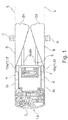
- FIGS. 1 to 4 in each case an inventive truck 1 is shown in a plan view.
- the truck 1 is designed as a reach truck 2 in the illustrated embodiments.
- the same components are provided in the figures with the same reference numerals.
- the reach truck 2 has a vehicle body 3, which has two mutually parallel wheel arms 3a, 3b, which extend in the vehicle longitudinal direction. Between the wheel arms 3a, 3b designed as a mast lifting mast 4 is arranged displaceably in the vehicle longitudinal direction. On the mast 4, a load-receiving means 5 is arranged raised and lowered, which is designed for example as a fork with two forks 6a, 6b.
- a roller is arranged, with which the truck 1 is supported on a roadway.
- a sensor device 10a, 10b for monitoring an environmental region is provided on the wheel arms 3a, 3b.
- a warning signal is generated and / or an intervention in the travel drive of the industrial truck 1 is carried out,
- the truck braked to avoid collision with the obstacle For example, the truck braked to avoid collision with the obstacle.
- the sensor devices 10a, 10b have corresponding detection areas D1, D2, which form the monitoring areas which are monitored for obstacles. If an obstacle is detected in the detection area D1, D2, a warning signal is generated and / or an intervention in the traction drive of the industrial truck 1 is carried out.
- the detection area D1, D2 are aligned with the area in front of the wheel arms 3a, 3b or in front of the load-receiving means 5 when the truck 1 travels ahead in the direction of travel with the load-receiving means 5.
- the sensor device 10a, 10b in the FIGS. 1 to 4 arranged such or arranged on the truck 1 that an obstacle H, for example, a shelf support of a shelf or parked pallet, which is located outside a line L, which is aligned with the vehicle outer contour K of the truck 1 and the vehicle outer contour (vehicle outer edge) K in Extended direction of travel of the truck 1, outside the detection range D1 or D2 of the sensor device 10a, 10b is located, in which generates a warning signal and / or an intervention in the traction drive of the truck is performed.
- an obstacle H for example, a shelf support of a shelf or parked pallet, which is located outside a line L, which is aligned with the vehicle outer contour K of the truck 1 and the vehicle outer contour (vehicle outer edge) K in Extended direction of travel of the truck 1, outside the detection range D1 or D2 of the sensor device 10a, 10b is located, in which generates a warning signal and / or an intervention in the traction drive of the truck is performed.
- the sensor device 10a, 10b is for this purpose in the FIGS. 1 to 4 arranged such or arranged on the truck 1, that the detection range D1, D2 of the sensor device 10a, 10b with an outer boundary edge B on or within the line L, which is aligned with the vehicle outer contour K of the truck 1 and the vehicle outer contour K in the direction of travel of the truck 1 extended.
- the outer boundary edge B of the detection area D1, D2 is arranged in a line with the vehicle outer contour K of the truck 1 or its extension in the direction of travel.
- the sensor devices 10a, 10b each have a single detection area D1, D2.
- the sensor devices 10a, 10b are configured as an ultrasonic sensor 11 or as a radar sensor 12 or as an inductive sensor.
- the sensor devices 10a, 10b are designed as a single-beam laser sensor 13.
- the sensor devices 10a, 10b are adjustably arranged on the industrial truck 1 by means of an adapter, not shown, in order to achieve the inventive alignment of the detection areas D1, D2 by appropriate arrangement and alignment of the sensor devices 10a, 10b, according to which the outer boundary edge B of the respective single Detection range D1, D2 in a line with the vehicle outer contour K of the truck 1 or its extension in the direction of travel.
- FIG. 2 is arranged on the Radarm 3b designed as an ultrasonic sensor 12 sensor device 10b, wherein the detection area D2 is formed in the form of a sound lobe.
- the detection area D2 is configured as an ultrasonic sensor 12 sensor device 10b, for example by means of an adapter not shown arranged on the truck 1 to achieve by appropriate arrangement and orientation of the ultrasonic sensor 12, the inventive alignment of the detection area D2, according to which the sound beam is parallel to the line L, which extends the vehicle outer contour K in the direction of travel and thus the outer boundary edge B of the detection area D1, D2 is in line with the vehicle outer contour K of the truck 1 and its extension in the direction of travel.
- the one-beam laser sensor 13 arranged on the wheel arm 3a is arranged on the industrial truck 1 in such a way that the laser beam forming the outer boundary edge B of the detection area D1 is aligned along the vehicle outer contour K and its extension in the direction of travel.
- the emitted laser beam is thus on the line L, which is aligned with the vehicle outer contour K and extends it in the direction of travel.
- the one-beam laser sensor 13 is arranged on the vehicle outer contour K for this purpose.
- a deflection mirror 15 is provided which deflects the emitted laser beam such that the outer boundary edge B of the detection area D1 forming laser beam along the vehicle outer contour K and their extension is aligned in the direction of travel, so that emitted laser beam is on the line L, which is aligned with the vehicle outer contour K and extends it in the direction of travel.
- the single-beam laser sensor 13 on the truck 1 further inside and thus be protected.
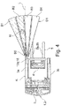
- FIG. 4 an industrial truck 1 is shown in which a sensor device 10a is arranged on the wheel arm 3a, which can monitor a plurality of regions B1-B5 in the detection area D1.
- the sensor device 10a of FIG. 4 is designed for example as a lidar sensor or time-of-flight camera 16 or stereo camera. Such sensor devices deliver a plurality of pixels in the detection region D1, so that a plurality of regions B1-B5 within the detection region D1 can be distinguished.
- This sensor device 10a is designed such that only those areas B3, B4, B5 are evaluated by the sensor device 10a for monitoring an obstacle, which are located within the vehicle contour K or its extension in the direction of travel (line L).
- the areas B1, B2 of the detection area D1 which protrude beyond a certain distance from the vehicle contour K or its extension in the direction of travel, are software-technologically considered only up to this distance for monitoring.
- the outgoing from the vehicle outer contour K or its extension in the direction of travel and thus beyond the line L areas B1, B2 can be switched off and thus excluded from the monitoring.
- a warning signal and / or an intervention in the traction drive of the truck 1 only takes place if an obstacle is detected in the areas B3, B4, B5 which form the monitored detection area D1.
- the shutdown of the protruding from the vehicle outer contour K areas B1, B2 can also be done in dependence on the steering angle of the truck 1, so that cornering of the truck can be considered.
- the inventive arrangement of the sensor device 10, 10b in the FIGS. 1 to 3 or the inventive design of the sensor device 10a of FIG. 4 be achieved, that if the truck 1 passes the obstacle H with a small lateral distance, the obstacle H is not in the detection range D1 or D2 of the sensor device 10a, 10b, in which generates a warning signal and / or a Intervention in the traction drive of the truck 1 is performed.
- the obstacle H is not recognized by the sensor device 10a, 10b and no warning signal is generated and / or no intervention in the traction drive of the industrial truck 1 is carried out.
- misdetections can be avoided when driving near the truck 1 on an obstacle H.
- an industrial truck 1 which is operated by a driver and an assistance system is provided which generates a warning signal at an obstacle detected in the detection area D1, D2 of the sensor device 10a, 10b and / or performs an intervention in the traction drive of the industrial truck 1, can According to the invention, when a warning signal is not generated on a barrier H when passing by near-by and / or no intervention is made in the travel drive of the industrial truck 1, the acceptance by the driver is increased.
- the invention is not limited to the illustrated embodiment of a truck 1 as a reach truck, but can also be used in other embodiments of industrial trucks 1, for example in a counterbalance forklift.
- the invention can also be used not only for one direction of travel with the load-receiving means 5 ahead, but also for the opposite or both directions of the truck. 1
- a deflection mirror 15 of the FIG. 3 can also be a signal of an ultrasonic sensor 11 are deflected and an ultrasonic sensor further inside and thus protected.
Abstract
Flurförderzeug (1) mit einer Sensoreinrichtung (10a; 10b) zur Überwachung eines Umgebungsbereiches, wobei bei einem von der Sensoreinrichtung (10a; 10b) in dem Umgebungsbereich erfassten Hindernis (H) ein Warnsignal erzeugt und/oder ein Eingriff in den Fahrantrieb des Flurförderzeugs (1) durchgeführt wird. Die Sensoreinrichtung (10a; 10b) ist derart ausgeführt oder derart am Flurförderzeug (1) angeordnet, dass sich ein Hindernis (H), das sich außerhalb einer Linie (L) befindet, die mit der Fahrzeugaußenkontur (K) des Flurförderzeugs (1) fluchtet und die Fahrzeugaußenkontur (K) in Fahrtrichtung des Flurförderzeugs (1) verlängert, außerhalb eines Detektionsbereichs (D1; D2) der Sensoreinrichtung (10a; 10b) befindet, in dem ein Warnsignal erzeugt und/oder eine Eingriff in den Fahrantrieb des Flurförderzeugs (1) durchgeführt wird.Industrial truck (1) with a sensor device (10a, 10b) for monitoring a surrounding area, wherein an obstacle (H) detected by the sensor device (10a, 10b) in the surrounding area generates a warning signal and / or an intervention in the traction drive of the industrial truck ( 1) is performed. The sensor device (10a, 10b) is designed in such a way or on the truck (1) arranged that an obstacle (H), which is outside a line (L), which is aligned with the vehicle outer contour (K) of the truck (1) and the vehicle outer contour (K) extended in the direction of travel of the industrial truck (1), outside a detection range (D1; D2) of the sensor device (10a; 10b), in which a warning signal is generated and / or an intervention in the traction drive of the industrial truck (1) is carried out.
Description
Die Erfindung betrifft ein Flurförderzeug mit einer Sensoreinrichtung zur Überwachung eines Umgebungsbereiches, wobei bei einem von der Sensoreinrichtung in dem Umgebungsbereich erfassten Hindernis ein Warnsignal erzeugt und/oder ein Eingriff in den Fahrantrieb des Flurförderzeugs durchgeführt wird.The invention relates to an industrial truck with a sensor device for monitoring a surrounding area, wherein a warning signal is generated at an obstacle detected by the sensor device in the surrounding area and / or an intervention in the traction drive of the industrial truck is performed.
Flurförderzeuge, die von einem Fahrer bedient sein können oder fahrerlos (autonom) betrieben sein können, sind mit einer als Umgebungssensor ausgebildeten Sensoreinrichtung versehen, die den im Fahrweg liegenden Umgebungsbereich und somit das Umfeld des Flurförderzeugs auf Hindernisse überwacht, um Kollisionen des Flurförderzeugs mit einem Hindernis zu vermeiden. Dies trifft insbesondere auf in Lagerbereichen betriebene Flurförderzeuge zu. Häufige Ausführungsformen derartiger Flurförderzeuge sind Schubmaststapler, Gegengewichtsgabelstapler oder Regalbediengeräte. Zur Erfassung und Überwachung des Umgebungsbereiches werden an derartigen Flurförderzeugen Sensoreinrichtungen eingesetzt, die laufzeitmessende Systeme sind, wie Ultraschall-, Radar- oder Lasersensoren, beispielsweise Laserscanner. Ebenso sind auch Bildverarbeitungssysteme bekannt, die aus einem Kamerabild oder einem Stereokamerabild die Umgebung erfassen, beispielsweise mittels einer Time-of-Flight-Kamera. Auch ist es bekannt, als Sensoreinrichtungen zur Überwachung des Umgebungsbereichs des Flurförderzeugs induktive Sensoren zu verwenden.Forklifts that can be operated by a driver or driverless (autonomous) can be operated, provided with an environmental sensor sensor device that monitors the lying in the road environment and thus the environment of the truck to obstacles to collisions of the truck with an obstacle to avoid. This applies in particular to industrial trucks operated in storage areas. Frequent embodiments of such industrial trucks are reach trucks, counterbalance forklifts or storage and retrieval units. For detecting and monitoring the surrounding area sensor devices are used on such trucks, which are term-measuring systems, such as ultrasonic, radar or laser sensors, such as laser scanners. Likewise, image processing systems are known which detect the environment from a camera image or a stereo camera image, for example by means of a time-of-flight camera. It is also known to use inductive sensors as sensor devices for monitoring the environmental area of the industrial truck.
Mit der an dem Flurförderzeug angeordneten Sensoreinrichtung werden Hindernisse im Fahrweg des Flurförderzeugs erkannt, und im Falle eines erkannten Hindernisses in dem Fahrweg ein Warnsignal ausgegeben und/oder durch einen Eingriff in den Fahrantrieb des Flurförderzeugs das Flurförderzeug angehalten, um eine Kollision mit dem Hindernis zu vermeiden. Derartige Sensoreinrichtungen können bei fahrerlos betriebenen, sogenannten autonom fahrenden Flurförderzeugen eingesetzt werden oder auch als Assistenzsysteme bei Flurförderzeugen, die von einem Fahrer bedient werden.With the arranged on the truck sensor device obstacles in the travel of the truck are detected, and issued in the case of a detected obstacle in the guideway warning and / or stopped by an intervention in the drive of the truck, the truck to avoid collision with the obstacle , Such sensor devices can be used in driverless operated, so-called autonomously moving industrial trucks or as assistance systems for industrial trucks that are operated by a driver.
Bei Schubmaststaplern, bei denen der Hubmast zwischen zwei Radarmen angeordnet ist, werden derartige Sensoreinrichtungen an den Radarmen verwendet, um das Anfahren des Schubmaststaplers mit den Radarmen an Hindernisse, beispielsweise Regalstützen eines Regals, zu vermeiden, wenn der Schubmaststapler zur Aufnahme oder zum Absetzen einer Last in Fahrtrichtung mit den Radarmen voraus gefahren wird. Die Sensoreinrichtungen sind an derartigen Schubmaststaplern an den Radarmen angeordnet und parallel zu den Gabelzinken eines als Lastgabel ausgebildeten Lastaufnahmemittels ausgerichtet, so dass die Sensoreinrichtungen seitlich an dem Lastaufnahmemittel vorbei nach vorne orientiert die Umgebung vor dem Lastaufnahmemittel bzw. vor den Radarmen erfassen.In reach trucks, in which the mast is arranged between two wheel arms, such sensor devices are used on the Radarmen to avoid the approach of the reach truck with the radar arms to obstacles, such as shelf supports a shelf, when the reach truck for receiving or for depositing a load is driven in the direction of travel with the Radarmen ahead. The sensor devices are arranged on such reach trucks on the Radarmen and aligned parallel to the forks of a load fork designed as a load receiving means, so that the sensor means laterally on the load receiving means forward oriented to capture the environment in front of the load receiving means or in front of the radar arms.
Bekannte Sensoreinrichtungen weisen einen Detektionsbereich auf, der seitlich über die Fahrzeugaußenkontur bzw. seitlich über die Verlängerung der Fahrzeugaußenkontur in Fahrtrichtung hinausragt. Sofern sich hierbei ein Hindernis nahe und somit mit geringem seitlichem Abstand neben dem Flurförderzeug befindet und somit das Flurförderzeugs mit geringem seitlichen Abstand an einem Hindernis vorbeifährt, kommt es zu Fehldetektionen, bei denen das seitlich neben dem Flurförderzeug befindliche Hindernis erkannt wird und ein Warnsignal erzeugt wird und/oder ein Eingriff in den Fahrantrieb des Flurförderzeugs erfolgt, beispielweise das Flurförderzeug abgebremst wird. Derartige Betriebssituationen, in denen Fehldetektionen durch ein Nahe-Vorbei-Fahren an einem Hindernis auftreten, sind das Einstapeln von Lasten in ein Regal, beispielsweise mittels eines Schubmaststaplers, wobei die seitlichen Abstände zu Regalstützen des Regals sehr gering sind und die Regalstützen als Hindernisse von der Sensoreinrichtung erkannt werden. Auch können derartige Betriebssituationen, in denen Fehldetektionen durch ein Nahe-Vorbei-Fahren an einem Hindernis auftreten, eine Einfahrt eines Flurförderzeugs in ein Drive-In-Regal, wobei die seitlichen Abstände zu Regalstützen des Regals sehr gering sind und die Regalstützen als Hindernisse von der Sensoreinrichtung erkannt werden, oder eine Einfahrt eines Flurförderzeugs in ein Blocklager sein, wobei die seitlichen Abstände zu abgestellten Paletten sehr gering sind und die abgestellten Paletten als Hindernisse von der Sensoreinrichtung erkannt werden. Fehldetektionen in derartigen Betriebssituationen erfolgen bei Sensoreinrichtungen, die den Bereich vor dem Lastaufnahmemittel des Flurförderzeugs bzw. vor den Radarmen eines als Schubmaststaplers ausgebildeten Flurförderzeugs überwachen, wenn das Flurförderzeug in Fahrtrichtung mit dem Lastaufnahmemittel voraus fährt.Known sensor devices have a detection area which projects laterally beyond the vehicle outer contour or laterally beyond the extension of the vehicle outer contour in the direction of travel. If this is an obstacle near and thus with a small lateral distance next to the truck and thus the truck passes with a small lateral distance past an obstacle, there are misdetections, in which the obstacle located laterally next to the truck is detected and a warning signal is generated and / or an intervention in the traction drive of the truck takes place, for example, the truck is braked. Such operating situations in which misdetections occur by a near-passing on an obstacle, the stacking of loads in a rack, for example by means of a reach truck, the lateral distances to shelf supports of the shelf are very low and the shelf supports as obstacles of the Sensor device can be detected. Also, such operating situations in which misdetections occur by a close-by driving on an obstacle, a driveway of a truck in a drive-in shelf, the lateral distances to shelf supports of the shelf are very low and the shelf supports as obstacles of the Detected sensor device, or be a gateway of a truck in a block storage, the lateral distances to parked pallets are very low and the parked pallets are recognized as obstacles from the sensor device. Misjudgements in such operating situations occur in sensor devices that monitor the area in front of the load-handling device of the industrial truck or in front of the arms of a truck designed as a reach truck when the truck moves in the direction of travel with the load-carrying means ahead.
Sofern das Flurförderzeug von einem Fahrer bedient wird und ein Assistenzsystem vorgesehen ist, das bei einem im Detektionsbereich der Sensoreinrichtung, der den Überwachungsbereich bildet, erkannten Hindernis ein Warnsignal erzeugt und/oder einen Eingriff in den Fahrantrieb des Flurförderzeugs durchgeführt, ist es für die Akzeptanz des Assistenzsystems durch den Fahrer sehr störend, wenn in Betriebssituationen, in denen das Flurförderzeugs mit geringem seitlichen Abstand an einem Hindernis, beispielsweise an einer Regalstütze und/oder an einer abgestellten Palette, vorbeifährt, die Sensoreinrichtung ein Hindernis detektiert und ein Warnsignal erzeugt wird und/oder ein Eingriff in den Fahrantrieb des Flurförderzeugs durchgeführt wird, beispielsweise eine Reduzierung der Fahrgeschwindigkeit auf Schleichfahrt erfolgt.If the truck is operated by a driver and an assistance system is provided which generates a warning signal in the detection area of the sensor device which forms the monitoring area, and / or performs an intervention in the traction drive of the industrial truck, it is for the acceptance of the truck Assistance system by the driver very disturbing when in operating situations in which the truck passes with a small lateral distance at an obstacle, for example on a rack support and / or on a parked pallet, the sensor device detects an obstacle and a warning signal is generated and / or an intervention in the traction drive of the truck is performed, for example, a reduction in the driving speed is carried out at creeping speed.
Aus der
Aus der
Der vorliegenden Erfindung liegt die Aufgabe zugrunde, ein Flurförderzeug der eingangs genannten Gattung zur Verfügung zu stellen, bei dem Fehldetektionen infolge eines Nahe-Vorbei-Fahrens des Flurförderzeugs mit geringem seitlichen Abstand an einem Hindernis und damit verbundene Warnsignale und/oder Eingriffe in den Fahrantrieb des Flurförderzeugs vermieden werden.The present invention has for its object to provide an industrial truck of the type mentioned in the misdetections due to a close-by driving the truck with a small lateral distance to an obstacle and related warning signals and / or interference with the drive of the Truck can be avoided.
Diese Aufgabe wird erfindungsgemäß dadurch gelöst, dass die Sensoreinrichtung derart ausgeführt oder derart am Flurförderzeug angeordnet ist, dass sich ein Hindernis, das sich außerhalb einer Linie befindet, die mit der Fahrzeugaußenkontur des Flurförderzeugs fluchtet und die Fahrzeugaußenkontur in Fahrtrichtung des Flurförderzeugs verlängert, außerhalb eines Detektionsbereichs der Sensoreinrichtung befindet, in dem ein Warnsignal erzeugt und/oder ein Eingriff in den Fahrantrieb des Flurförderzeugs durchgeführt wird. Erfindungsgemäß ist die Sensoreinrichtung derart ausgeführt oder derart am Flurförderzeug angeordnet, dass sich ein Hindernis, das außerhalb der Fahrzeugaußenkontur des Flurförderzeugs und der Verlängerung der Fahrzeugaußenkontur in Fahrtrichtung angeordnet ist, sich nicht mehr im Detektionsbereichs der Sensoreinrichtung befindet, in dem ein Warnsignal erzeugt und/oder ein Eingriff in den Fahrantrieb des Flurförderzeugs bewirkt wird. Eine derartige Ausführung bzw. Anordnung der Sensoreinrichtung ermöglicht es auf einfache Weise, dass Fehldetektionen vermieden werden, wenn ein Nahe-Vorbei-Fahren des Flurförderzeugs mit geringem seitlichen Abstand an einem Hindernis erfolgt. Mit dem erfindungsgemäßen Flurförderzeug kann somit ein Nahe-Vorbei-Fahren des Flurförderzeugs mit geringem seitlichen Abstand an einem Hindernis erfolgen, ohne dass die Sensoreinrichtung ein Hindernis erkennt und somit kein entsprechendes Warnsignal erzeugt wird und/oder kein Eingriff in den Fahrantrieb des Flurförderzeugs erfolgt.This object is achieved in that the sensor device is designed or arranged on the truck that an obstacle that is outside a line that is aligned with the vehicle outer contour of the truck and extends the vehicle outer contour in the direction of travel of the truck, outside of a detection area the sensor device is located, in which generates a warning signal and / or an intervention in the traction drive of the truck is performed. According to the invention, the sensor device is such executed or arranged on the truck so that an obstacle, which is located outside the vehicle outer contour of the truck and the extension of the vehicle outer contour in the direction of travel, is no longer in the detection range of the sensor device in which generates a warning signal and / or interference with the traction drive of the truck is effected. Such a design or arrangement of the sensor device makes it possible in a simple way that misdetections are avoided when a close-by driving the truck takes place with a small lateral distance at an obstacle. Thus, with the truck according to the invention, a close-ahead driving of the truck with a small lateral distance to an obstacle can be done without the sensor device detects an obstacle and thus no corresponding warning signal is generated and / or no intervention in the traction drive of the truck.
Gemäß einer vorteilhaften Ausgestaltungsform der Erfindung ist die Sensoreinrichtung derart ausgeführt oder derart am Flurförderzeug angeordnet, dass der Detektionsbereich der Sensoreinrichtung mit einer äußeren Begrenzungskante auf oder innerhalb der Linie ist, die mit der Fahrzeugaußenkontur des Flurförderzeugs fluchtet und die Fahrzeugaußenkontur in Fahrtrichtung des Flurförderzeugs verlängert. Die äußere Begrenzungskante des Detektionsbereichs der Sensoreinrichtung ragt somit nicht über die Fahrzeugaußenkontur und deren Verlängerung in Fahrtrichtung hinaus, wodurch auf einfache Weise erzielt wird, dass beim Nahe-Vorbei-Fahren des Flurförderzeugs mit geringem seitlichen Abstand an einem Hindernis kein entsprechendes Warnsignal erzeugt wird und/oder kein Eingriff in den Fahrantrieb des Flurförderzeugs erfolgt.According to an advantageous embodiment of the invention, the sensor device is designed or arranged on the truck that the detection range of the sensor device with an outer boundary edge on or within the line, which is aligned with the vehicle outer contour of the truck and extends the vehicle outer contour in the direction of travel of the truck. The outer boundary edge of the detection range of the sensor device thus does not protrude beyond the vehicle outer contour and its extension in the direction of travel, which is achieved in a simple manner that when driving close the truck with a small lateral distance at an obstacle no corresponding warning signal is generated and / or no intervention in the traction drive of the truck takes place.
Bevorzugt ist gemäß einer vorteilhaften Ausgestaltungsform der Erfindung die äußere Begrenzungskante des Detektionsbereichs in einer Linie mit der Fahrzeugaußenkontur des Flurförderzeugs angeordnet. Die äußere Begrenzungskante des Detektionsbereichs der Sensoreinrichtung befindet sich somit in einer Linie mit der Fahrzeugaußenkontur und deren Verlängerung in Fahrtrichtung hinaus.Preferably, according to an advantageous embodiment of the invention, the outer boundary edge of the detection area is arranged in a line with the vehicle outer contour of the truck. The outer boundary edge of the detection range of the sensor device is thus in a line with the vehicle outer contour and its extension in the direction of travel also.
Bevorzugt ist gemäß einer alternativen und ebenfalls vorteilhaften Ausgestaltungsform der Erfindung der Detektionsbereich parallel zu der die Fahrzeugaußenkontur in Fahrtrichtung des Flurförderzeugs verlängernden Linie ausgerichtet. Der Detektionsbereich der Sensoreinrichtung ist somit mit parallel zur Verlängerung der Fahrzeugaußenkontur in Fahrtrichtung hinaus ausgerichtet. Hierdurch kann bei einem keulenförmigen Detektionsbereich auf einfache Weise erzielt werden, dass der keulenförmige Detektionsbereich parallel zur Fahrzeugaußenkontur ausgerichtet ist und die äußere Begrenzungskante des Detektionsbereiches nicht über die Verlängerung der Fahrzeugaußenkontur hinausragt.Preferably, according to an alternative and likewise advantageous embodiment of the invention, the detection area is aligned parallel to the line extending the vehicle outer contour in the direction of travel of the industrial truck. Of the Detection range of the sensor device is thus aligned parallel to the extension of the vehicle outer contour in the direction of travel. In this way, it can be achieved in a club-shaped detection area in a simple manner that the club-shaped detection area is aligned parallel to the vehicle outer contour and the outer boundary edge of the detection area does not protrude beyond the extension of the vehicle outer contour.
Gemäß einer vorteilhaften Ausgestaltungsform der Erfindung weist die Sensoreinrichtung einen einzigen Detektionsbereich auf. Bei einer Sensoreinrichtung, die einen einzigen Detektionsbereich aufweist, kann durch eine entsprechende Anordnung und somit Ausrichtung der Sensoreinrichtung am Flurförderzeug auf einfache Weise erzielt werden, dass der Detektionsbereich der Sensoreinrichtung mit der äußeren Begrenzungskante auf oder innerhalb der Linie ist, die mit der Fahrzeugaußenkontur des Flurförderzeugs fluchtet und die Fahrzeugaußenkontur in Fahrtrichtung des Flurförderzeugs verlängert.According to an advantageous embodiment of the invention, the sensor device has a single detection area. In the case of a sensor device which has a single detection region, it can be achieved in a simple manner by a corresponding arrangement and thus alignment of the sensor device on the industrial truck that the detection region of the sensor device with the outer boundary edge is on or within the line with the vehicle outer contour of the industrial truck is aligned and extends the vehicle outer contour in the direction of travel of the truck.
Derartige Sensoreinrichtungen können als Ultraschallsensor oder als Radarsensor oder als induktiver Sensor oder als Laserstrahlsensor, insbesondere Ein-Strahl-Lasersensor, ausgebildet sein.Such sensor devices can be designed as an ultrasonic sensor or as a radar sensor or as an inductive sensor or as a laser beam sensor, in particular a single-beam laser sensor.
Eine entsprechende Anordnung und Ausrichtung einer derartigen Sensoreinrichtung kann auf einfache Weise erzielt werden, wenn gemäß einer vorteilhaften Ausgestaltungsform der Erfindung die Sensoreinrichtung mittels eines Adapters einstellbar am Flurförderzeug angeordnet ist. Durch entsprechende Verstellung der Sensoreinrichtung mittels des Adapters kann auf einfache und schnelle Weise die Sensoreinrichtung derart ausgerichtet werden, dass der Detektionsbereich der Sensoreinrichtung mit einer äußeren Begrenzungskante auf oder innerhalb der Linie ist, die mit der Fahrzeugaußenkontur des Flurförderzeugs fluchtet und die Fahrzeugaußenkontur in Fahrtrichtung des Flurförderzeugs verlängert.A corresponding arrangement and orientation of such a sensor device can be achieved in a simple manner, if according to an advantageous embodiment of the invention, the sensor device is arranged by means of an adapter adjustable on the truck. By appropriate adjustment of the sensor device by means of the adapter, the sensor device can be aligned in a simple and fast manner such that the detection range of the sensor device is with an outer boundary edge on or within the line, which is aligned with the vehicle outer contour of the truck and the vehicle outer contour in the direction of travel of the truck extended.
Gemäß einer alternativen Ausführungsform der Erfindung ist ein Umlenkspiegel vorgesehen, der den Detektionsbereich der Sensoreinrichtung auf oder innerhalb der in Fahrtrichtung des Flurförderzeugs verlängerten Fahrzeugaußenkontur des Flurförderzeugs hält. Mit einem Umlenkspiegel kann insbesondere bei der Ausbildung der Sensoreinrichtung als Ein-Strahl-Lasersensor der Laserstrahl und somit die äußere Begrenzungskante des Detektionsbereichs auf oder innerhalb der Linie gehalten werden, die mit der Fahrzeugaußenkontur des Flurförderzeugs fluchtet und die Fahrzeugaußenkontur in Fahrtrichtung des Flurförderzeugs verlängert.According to an alternative embodiment of the invention, a deflection mirror is provided, which holds the detection range of the sensor device on or within the extended in the direction of travel of the truck vehicle outer contour of the truck. With a deflecting mirror, in particular in the case of the embodiment of the sensor device as a single-beam laser sensor, the laser beam and thus the outer one Limited boundary of the detection area are held on or within the line, which is aligned with the vehicle outer contour of the truck and extends the vehicle outer contour in the direction of travel of the truck.
Gemäß einer alternativen Ausführungsform der Erfindung überwacht die Sensoreinrichtung in dem Detektionsbereich mehrere Bereiche. Bei einer Sensoreinrichtung, die mehrere Bereiche innerhalb des Detektionsbereichs überwacht und somit mehrere Bereiche innerhalb des Detektionsbereichs unterscheidet, können vorteilhafterweise nur diejenigen Bereiche ausgewertet werden, die innerhalb der Fahrzeugaußenkontur und deren Verlängerung in Fahrtrichtung liegen, um Fehldetektionen beim Nahe-Vorbei-Fahren des Flurförderzeugs mit geringem seitlichen Abstand an einem Hindernis zu verhindern.According to an alternative embodiment of the invention, the sensor device monitors several areas in the detection area. In the case of a sensor device which monitors a plurality of regions within the detection region and thus differentiates several regions within the detection region, advantageously only those regions which lie within the vehicle outer contour and its extension in the direction of travel can be evaluated in order to detect misdetections during the near-by driving of the industrial truck small lateral distance to prevent an obstacle.
Hierzu werden gemäß einer vorteilhaften Ausführungsform der Erfindung diejenigen Bereiche des Detektionsbereiches abgeschaltet, die sich außerhalb der Linie befinden, die mit der Fahrzeugaußenkontur des Flurförderzeugs fluchtet und die Fahrzeugaußenkontur in Fahrtrichtung des Flurförderzeugs verlängert. Das Abschalten kann beispielsweise softwaretechnisch erfolgen, in dem bestimmte Bereiche des Detektionsbereichs, die bei einer bestimmten Entfernung aus der Fahrzeugkontur bzw. deren Verlängerung in Fahrtrichtung hinausgehen, softwaretechnisch nur bis zu dieser Entfernung berücksichtigt werden.For this purpose, according to an advantageous embodiment of the invention those areas of the detection area are switched off, which are located outside the line, which is aligned with the vehicle outer contour of the truck and extends the vehicle outer contour in the direction of travel of the truck. Switching off can be done, for example, by software, in which certain areas of the detection area, which at a certain distance from the vehicle contour or its extension in the direction of travel go, are considered software only up to this distance.
Gemäß einer vorteilhaften Weiterbildung der Erfindung erfolgt die Abschaltung der Bereiche in Abhängigkeit von dem Lenkwinkel des Flurförderzeugs. Dadurch kann auf einfache Weise eine Kurvenfahrt berücksichtigt werden. Hierzu kann beispielsweise eine Trajektorie berechnet werden und die Überwachung der Bereiche außerhalb dieser Trajektorie ausgeschlossen werden.According to an advantageous embodiment of the invention, the shutdown of the areas takes place in dependence on the steering angle of the truck. As a result, cornering can be taken into account in a simple manner. For this purpose, for example, a trajectory can be calculated and the monitoring of the areas outside this trajectory can be excluded.
Eine derartige Sensoreinrichtung kann als Lidar (Light detection and ranging)-Sensor oder Time-of-Flight-Kamera oder Stereokamera ausgebildet sein. Derartige Sensoreinrichtungen weisen im Überwachungsbereich viele Bildpunkte auf, so dass mehrere Bereiche innerhalb des Detektionsbereichs unterschieden werden können und somit diejenigen Bereich von der Überwachung abgeschaltet und somit ausgeschlossen werden können, die aus der Fahrzeugaußenkontur und deren Verlängerung in Fahrtrichtung herausragen.Such a sensor device can be designed as a lidar (light detection and ranging) sensor or time-of-flight camera or stereo camera. Such sensor devices have many pixels in the monitoring area, so that a plurality of areas within the detection area can be distinguished and thus those areas can be switched off from the monitoring and thus excluded, which protrude from the vehicle outer contour and its extension in the direction of travel.
Weitere Vorteile und Einzelheiten der Erfindung werden anhand der in den schematischen Figuren dargestellten Ausführungsbeispiele näher erläutert. Hierbei zeigt
- Figur 1
- eine erste Ausführungsform eines erfindungsgemäßen Flurförderzeug,
- Figur 2
- eine zweite Ausführungsform eines erfindungsgemäßen Flurförderzeug,
Figur 3- zwei weitere Ausführungsformen eines erfindungsgemäßen Flurförderzeugs und
Figur 4- eine weitere Ausführungsformen eines erfindungsgemäßen Flurförderzeugs.
- FIG. 1
- a first embodiment of an industrial truck according to the invention,
- FIG. 2
- a second embodiment of an industrial truck according to the invention,
- FIG. 3
- two further embodiments of a truck according to the invention and
- FIG. 4
- a further embodiments of an industrial truck according to the invention.
In den
Der Schubmaststapler 2 weist einen Fahrzeugkörper 3 auf, der zwei parallel zueinander angeordnete Radarme 3a, 3b aufweist, die sich in Fahrzeuglängsrichtung erstrecken. Zwischen den Radarmen 3a, 3b ist ein als Schubmast ausgebildeter Hubmast 4 in Fahrzeuglängsrichtung verschiebbar angeordnet. An dem Hubmast 4 ist ein Lastaufnahmemittel 5 anhebbar und absenkbar angeordnet, das beispielsweise als Lastgabel mit zwei Gabelzinken 6a, 6b ausgeführt ist.The reach truck 2 has a
An den vorderen Enden der Radarme 3a, 3b ist jeweils eine Laufrolle angeordnet, mit denen sich das Flurförderzeug 1 auf einer Fahrbahn abstützt.At the front ends of the
An den Radarmen 3a, 3b ist jeweils eine Sensoreinrichtung 10a, 10b zur Überwachung eines Umgebungsbereiches vorgesehen. Bei einem von der Sensoreinrichtung 10a, 10b in dem Umgebungsbereich erfassten Hindernis wird ein Warnsignal erzeugt und/oder ein Eingriff in den Fahrantrieb des Flurförderzeugs 1 durchgeführt, beispielsweise das Flurförderzeug abgebremst, um eine Kollision mit dem Hindernis zu vermeiden. Die Sensoreinrichtungen 10a, 10b weisen hierzu entsprechende Detektionsbereiche D1, D2 auf, die die Überwachungsbereiche bilden, die auf Hindernisse überwacht werden. Sofern in dem Detektionsbereich D1, D2 ein Hindernis erfasst wird, wird ein Warnsignal erzeugt und/oder ein Eingriff in den Fahrantrieb des Flurförderzeugs 1 durchgeführt. Die Detektionsbereich D1, D2 sind auf den Bereich vor die Radarme 3a, 3b bzw. vor das Lastaufnahmemittel 5 ausgerichtet, wenn das Flurförderzeug 1 in Fahrtrichtung mit dem Lastaufnahmemittel 5 voraus fährt.In each case, a
Erfindungsgemäß ist die Sensoreinrichtung 10a, 10b in den
Die Sensoreinrichtung 10a, 10b ist hierzu in den
In den
In den
In der
In der
In der
In der
In der
Durch den Umlenkspiegel 15 kann der Ein-Strahl-Lasersensor 13 an dem Flurförderzeug 1 weiter innen und somit geschützter angeordnet werden.By the deflecting
In der
In der
Wie aus den
Bei einem Flurförderzeug 1, das von einem Fahrer bedient wird und ein Assistenzsystem vorgesehen ist, das bei einem im Detektionsbereich D1, D2 der Sensoreinrichtung 10a, 10b erkannten Hindernis ein Warnsignal erzeugt und/oder einen Eingriff in den Fahrantrieb des Flurförderzeugs 1 durchgeführt, kann mit der Erfindung, gemäß der bei einem Nahe-Vorbei-Fahren an einem Hindernis H kein Warnsignal erzeugt und/oder kein Eingriff in den Fahrantrieb des Flurförderzeugs 1 durchgeführt wird, die Akzeptanz bei dem Fahrer erhöht werden.In an industrial truck 1, which is operated by a driver and an assistance system is provided which generates a warning signal at an obstacle detected in the detection area D1, D2 of the
Die Erfindung ist nicht auf das dargestellte Ausführungsbeispiel eines Flurförderzeugs 1 als Schubmaststapler beschränkt, sondern kann auch bei anderen Ausführungsformen von Flurförderzeugen 1 eingesetzt werden, beispielsweise bei einem Gegengewichtsgabelstapler. Die Erfindung kann zudem nicht nur für eine Fahrtrichtung mit dem Lastaufnahmemittel 5 voraus eingesetzt werden, sondern auch für die entgegengesetzte oder beide Fahrtrichtungen des Flurförderzeugs 1.The invention is not limited to the illustrated embodiment of a truck 1 as a reach truck, but can also be used in other embodiments of industrial trucks 1, for example in a counterbalance forklift. The invention can also be used not only for one direction of travel with the load-receiving means 5 ahead, but also for the opposite or both directions of the truck. 1
Durch einen Umlenkspiegel 15 der
Claims (12)
Applications Claiming Priority (1)
| Application Number | Priority Date | Filing Date | Title |
|---|---|---|---|
| DE102016120117.0A DE102016120117A1 (en) | 2016-10-21 | 2016-10-21 | Industrial truck with a sensor device for monitoring a surrounding area |
Publications (2)
| Publication Number | Publication Date |
|---|---|
| EP3312131A1 true EP3312131A1 (en) | 2018-04-25 |
| EP3312131B1 EP3312131B1 (en) | 2023-07-12 |
Family
ID=59974341
Family Applications (1)
| Application Number | Title | Priority Date | Filing Date |
|---|---|---|---|
| EP17193765.9A Active EP3312131B1 (en) | 2016-10-21 | 2017-09-28 | Industrial truck with a sensor device for monitoring an ambient area |
Country Status (2)
| Country | Link |
|---|---|
| EP (1) | EP3312131B1 (en) |
| DE (1) | DE102016120117A1 (en) |
Cited By (6)
| Publication number | Priority date | Publication date | Assignee | Title |
|---|---|---|---|---|
| EP3587894A1 (en) * | 2018-06-28 | 2020-01-01 | Leuze electronic GmbH + Co. KG | Sensor assembly and method for operating a sensor assembly |
| CN115072316A (en) * | 2022-08-01 | 2022-09-20 | 安徽行者智能科技股份有限公司 | Multifunctional transfer module for large-size complex curved surface intelligent processing system |
| EP4137437A1 (en) * | 2021-08-17 | 2023-02-22 | Schiller Automatisierungstechnik GmbH | Method for operating an industrial vehicle |
| WO2023020940A1 (en) * | 2021-08-17 | 2023-02-23 | Schiller Automatisierungstechnik Gmbh | Method for operating a conveying means |
| EP4183737A1 (en) * | 2021-11-19 | 2023-05-24 | Jungheinrich Aktiengesellschaft | Method for handling disturbances in industrial trucks |
| US11820634B2 (en) | 2020-02-21 | 2023-11-21 | Crown Equipment Corporation | Modify vehicle parameter based on vehicle position information |
Families Citing this family (5)
| Publication number | Priority date | Publication date | Assignee | Title |
|---|---|---|---|---|
| DE102018117214A1 (en) * | 2018-07-17 | 2020-01-23 | Jungheinrich Aktiengesellschaft | Reach truck with a monitoring sensor and a method for operating such |
| DE102018128406B4 (en) * | 2018-11-13 | 2023-05-11 | Jungheinrich Aktiengesellschaft | Industrial truck with an emergency stop system |
| DE102019213922A1 (en) * | 2019-09-12 | 2021-03-18 | Jungheinrich Aktiengesellschaft | Vehicle with environment monitoring device |
| DE102020207479A1 (en) | 2020-06-17 | 2021-12-23 | Zf Friedrichshafen Ag | Fork arm sensors for the detection of cross traffic |
| DE102021103799A1 (en) | 2021-02-18 | 2022-08-18 | Jungheinrich Aktiengesellschaft | INDUSTRIAL TRUCK WITH DETECTION DEVICES ON THE FORKS |
Citations (8)
| Publication number | Priority date | Publication date | Assignee | Title |
|---|---|---|---|---|
| JPS5950379A (en) * | 1982-09-16 | 1984-03-23 | Nippon Denso Co Ltd | Obstacle detecting device for vehicle |
| GB2157436A (en) * | 1984-04-06 | 1985-10-23 | Bygg Och Transportekonomie Ab | Detecting obstacles in the operation of remote-controlled machines |
| JPS6327398A (en) * | 1986-07-22 | 1988-02-05 | 株式会社豊田自動織機製作所 | Safety device for unmanned forklift |
| US4802096A (en) * | 1987-05-14 | 1989-01-31 | Bell & Howell Company | Controlled direction non-contact detection system for automatic guided vehicles |
| EP0800129B1 (en) | 1996-04-03 | 2000-07-19 | FIAT OM CARRELLI ELEVATORI S.p.A. | Industrial truck with manual or automatic mode |
| DE102008008922A1 (en) | 2008-02-13 | 2009-08-20 | Still Gmbh | Ground conveyor has vehicle longitudinal direction extending wheel arm, which is arranged at loading pulley, where environment sensor is arranged in range of wheel arm |
| EP2339376A1 (en) * | 2009-12-17 | 2011-06-29 | Sick Ag | Optoelectronic sensor |
| JP2015170284A (en) * | 2014-03-10 | 2015-09-28 | 株式会社日立製作所 | Forklift type unmanned carrier vehicle, control method of the same, and control device of the same |
-
2016
- 2016-10-21 DE DE102016120117.0A patent/DE102016120117A1/en active Pending
-
2017
- 2017-09-28 EP EP17193765.9A patent/EP3312131B1/en active Active
Patent Citations (8)
| Publication number | Priority date | Publication date | Assignee | Title |
|---|---|---|---|---|
| JPS5950379A (en) * | 1982-09-16 | 1984-03-23 | Nippon Denso Co Ltd | Obstacle detecting device for vehicle |
| GB2157436A (en) * | 1984-04-06 | 1985-10-23 | Bygg Och Transportekonomie Ab | Detecting obstacles in the operation of remote-controlled machines |
| JPS6327398A (en) * | 1986-07-22 | 1988-02-05 | 株式会社豊田自動織機製作所 | Safety device for unmanned forklift |
| US4802096A (en) * | 1987-05-14 | 1989-01-31 | Bell & Howell Company | Controlled direction non-contact detection system for automatic guided vehicles |
| EP0800129B1 (en) | 1996-04-03 | 2000-07-19 | FIAT OM CARRELLI ELEVATORI S.p.A. | Industrial truck with manual or automatic mode |
| DE102008008922A1 (en) | 2008-02-13 | 2009-08-20 | Still Gmbh | Ground conveyor has vehicle longitudinal direction extending wheel arm, which is arranged at loading pulley, where environment sensor is arranged in range of wheel arm |
| EP2339376A1 (en) * | 2009-12-17 | 2011-06-29 | Sick Ag | Optoelectronic sensor |
| JP2015170284A (en) * | 2014-03-10 | 2015-09-28 | 株式会社日立製作所 | Forklift type unmanned carrier vehicle, control method of the same, and control device of the same |
Cited By (7)
| Publication number | Priority date | Publication date | Assignee | Title |
|---|---|---|---|---|
| EP3587894A1 (en) * | 2018-06-28 | 2020-01-01 | Leuze electronic GmbH + Co. KG | Sensor assembly and method for operating a sensor assembly |
| US11820634B2 (en) | 2020-02-21 | 2023-11-21 | Crown Equipment Corporation | Modify vehicle parameter based on vehicle position information |
| US11912550B2 (en) | 2020-02-21 | 2024-02-27 | Crown Equipment Corporation | Position assistance system for a materials handling vehicle |
| EP4137437A1 (en) * | 2021-08-17 | 2023-02-22 | Schiller Automatisierungstechnik GmbH | Method for operating an industrial vehicle |
| WO2023020940A1 (en) * | 2021-08-17 | 2023-02-23 | Schiller Automatisierungstechnik Gmbh | Method for operating a conveying means |
| EP4183737A1 (en) * | 2021-11-19 | 2023-05-24 | Jungheinrich Aktiengesellschaft | Method for handling disturbances in industrial trucks |
| CN115072316A (en) * | 2022-08-01 | 2022-09-20 | 安徽行者智能科技股份有限公司 | Multifunctional transfer module for large-size complex curved surface intelligent processing system |
Also Published As
| Publication number | Publication date |
|---|---|
| DE102016120117A1 (en) | 2018-04-26 |
| EP3312131B1 (en) | 2023-07-12 |
Similar Documents
| Publication | Publication Date | Title |
|---|---|---|
| EP3312131A1 (en) | Industrial truck with a sensor device for monitoring an ambient area | |
| EP2339376B1 (en) | Optoelectronic sensor | |
| EP2692688B1 (en) | Driving aid device for an industrial truck and industrial truck | |
| EP2692687B1 (en) | Driving aid device and an industrial truck with driving aid device | |
| EP2240350B1 (en) | Use of a wheel guide rail, car wash system and method for centrally positioning a vehicle | |
| EP0800129B1 (en) | Industrial truck with manual or automatic mode | |
| EP3132859B1 (en) | Conveying device with collision detection | |
| EP3241801B1 (en) | Method for collision monitoring in an industrial truck | |
| DE102010028911A1 (en) | Method for monitoring movement of vehicle i.e. fork lift lorry, involves detecting collision hazard of vehicle by obstruction placed in region of curved travel path, or leaving curved travel path by vehicle | |
| EP3369696B1 (en) | Industrial truck with sensor concept and industrial truck | |
| EP3511289B1 (en) | Method for controlling an industrial truck and a system comprising a superordinate control unit and an industrial truck | |
| WO2018073097A1 (en) | Arrangement of a gantry lifting device and of a row of spaced-apart marking elements | |
| EP3772483A1 (en) | Method for determining the motion of an industrial truck | |
| DE102019215176A1 (en) | Industrial truck, set up for driverless, autonomous operation for a load to be transported | |
| DE10221298A1 (en) | Wheeled goods handling vehicle has sensors that are used to detect the presence of objects or people and allow controller to apply braking system | |
| EP3800158A1 (en) | Industrial truck equipped for driverless autonomous operation for a load to be transported | |
| EP2801489B1 (en) | Industrial truck for a route train | |
| EP4136049B1 (en) | Industrial truck with load receiving means for receiving elongated goods | |
| EP4046958B1 (en) | Industrial truck with detecting devices on fork tines | |
| DE3214391A1 (en) | Automotive vehicle | |
| DE102019215174A1 (en) | Industrial truck, set up for driverless, autonomous operation | |
| EP2172414A1 (en) | Industrial truck led by a drawbar | |
| EP3210865B1 (en) | Industrial truck with a drive and a driver platform for a standing operator | |
| DE102021133615A1 (en) | Method for operating an industrial truck and industrial truck | |
| DE102020215149A1 (en) | Method for operating a vehicle in a rack aisle depending on route information |
Legal Events
| Date | Code | Title | Description |
|---|---|---|---|
| PUAI | Public reference made under article 153(3) epc to a published international application that has entered the european phase |
Free format text: ORIGINAL CODE: 0009012 |
|
| STAA | Information on the status of an ep patent application or granted ep patent |
Free format text: STATUS: THE APPLICATION HAS BEEN PUBLISHED |
|
| AK | Designated contracting states |
Kind code of ref document: A1 Designated state(s): AL AT BE BG CH CY CZ DE DK EE ES FI FR GB GR HR HU IE IS IT LI LT LU LV MC MK MT NL NO PL PT RO RS SE SI SK SM TR |
|
| AX | Request for extension of the european patent |
Extension state: BA ME |
|
| STAA | Information on the status of an ep patent application or granted ep patent |
Free format text: STATUS: REQUEST FOR EXAMINATION WAS MADE |
|
| 17P | Request for examination filed |
Effective date: 20181018 |
|
| RBV | Designated contracting states (corrected) |
Designated state(s): AL AT BE BG CH CY CZ DE DK EE ES FI FR GB GR HR HU IE IS IT LI LT LU LV MC MK MT NL NO PL PT RO RS SE SI SK SM TR |
|
| STAA | Information on the status of an ep patent application or granted ep patent |
Free format text: STATUS: EXAMINATION IS IN PROGRESS |
|
| 17Q | First examination report despatched |
Effective date: 20200902 |
|
| STAA | Information on the status of an ep patent application or granted ep patent |
Free format text: STATUS: EXAMINATION IS IN PROGRESS |
|
| STAA | Information on the status of an ep patent application or granted ep patent |
Free format text: STATUS: EXAMINATION IS IN PROGRESS |
|
| REG | Reference to a national code |
Ref document number: 502017015035 Country of ref document: DE Ref country code: DE Ref legal event code: R079 Free format text: PREVIOUS MAIN CLASS: B66F0017000000 Ipc: B66F0009075000 |
|
| GRAP | Despatch of communication of intention to grant a patent |
Free format text: ORIGINAL CODE: EPIDOSNIGR1 |
|
| STAA | Information on the status of an ep patent application or granted ep patent |
Free format text: STATUS: GRANT OF PATENT IS INTENDED |
|
| RIC1 | Information provided on ipc code assigned before grant |
Ipc: B66F 17/00 20060101ALI20230220BHEP Ipc: B66F 9/075 20060101AFI20230220BHEP |
|
| INTG | Intention to grant announced |
Effective date: 20230329 |
|
| GRAS | Grant fee paid |
Free format text: ORIGINAL CODE: EPIDOSNIGR3 |
|
| GRAA | (expected) grant |
Free format text: ORIGINAL CODE: 0009210 |
|
| STAA | Information on the status of an ep patent application or granted ep patent |
Free format text: STATUS: THE PATENT HAS BEEN GRANTED |
|
| P01 | Opt-out of the competence of the unified patent court (upc) registered |
Effective date: 20230507 |
|
| AK | Designated contracting states |
Kind code of ref document: B1 Designated state(s): AL AT BE BG CH CY CZ DE DK EE ES FI FR GB GR HR HU IE IS IT LI LT LU LV MC MK MT NL NO PL PT RO RS SE SI SK SM TR |
|
| REG | Reference to a national code |
Ref country code: CH Ref legal event code: EP |
|
| REG | Reference to a national code |
Ref country code: DE Ref legal event code: R096 Ref document number: 502017015035 Country of ref document: DE |
|
| REG | Reference to a national code |
Ref country code: IE Ref legal event code: FG4D Free format text: LANGUAGE OF EP DOCUMENT: GERMAN |
|
| REG | Reference to a national code |
Ref country code: SE Ref legal event code: TRGR |
|
| PGFP | Annual fee paid to national office [announced via postgrant information from national office to epo] |
Ref country code: GB Payment date: 20230921 Year of fee payment: 7 |
|
| REG | Reference to a national code |
Ref country code: LT Ref legal event code: MG9D |
|
| REG | Reference to a national code |
Ref country code: NL Ref legal event code: MP Effective date: 20230712 |
|
| PGFP | Annual fee paid to national office [announced via postgrant information from national office to epo] |
Ref country code: SE Payment date: 20230921 Year of fee payment: 7 Ref country code: FR Payment date: 20230918 Year of fee payment: 7 Ref country code: DE Payment date: 20230919 Year of fee payment: 7 |
|
| PG25 | Lapsed in a contracting state [announced via postgrant information from national office to epo] |
Ref country code: NL Free format text: LAPSE BECAUSE OF FAILURE TO SUBMIT A TRANSLATION OF THE DESCRIPTION OR TO PAY THE FEE WITHIN THE PRESCRIBED TIME-LIMIT Effective date: 20230712 |
|
| PG25 | Lapsed in a contracting state [announced via postgrant information from national office to epo] |
Ref country code: GR Free format text: LAPSE BECAUSE OF FAILURE TO SUBMIT A TRANSLATION OF THE DESCRIPTION OR TO PAY THE FEE WITHIN THE PRESCRIBED TIME-LIMIT Effective date: 20231013 |
|
| PG25 | Lapsed in a contracting state [announced via postgrant information from national office to epo] |
Ref country code: ES Free format text: LAPSE BECAUSE OF FAILURE TO SUBMIT A TRANSLATION OF THE DESCRIPTION OR TO PAY THE FEE WITHIN THE PRESCRIBED TIME-LIMIT Effective date: 20230712 |
|
| PG25 | Lapsed in a contracting state [announced via postgrant information from national office to epo] |
Ref country code: IS Free format text: LAPSE BECAUSE OF FAILURE TO SUBMIT A TRANSLATION OF THE DESCRIPTION OR TO PAY THE FEE WITHIN THE PRESCRIBED TIME-LIMIT Effective date: 20231112 |
|
| PG25 | Lapsed in a contracting state [announced via postgrant information from national office to epo] |
Ref country code: RS Free format text: LAPSE BECAUSE OF FAILURE TO SUBMIT A TRANSLATION OF THE DESCRIPTION OR TO PAY THE FEE WITHIN THE PRESCRIBED TIME-LIMIT Effective date: 20230712 Ref country code: PT Free format text: LAPSE BECAUSE OF FAILURE TO SUBMIT A TRANSLATION OF THE DESCRIPTION OR TO PAY THE FEE WITHIN THE PRESCRIBED TIME-LIMIT Effective date: 20231113 Ref country code: NO Free format text: LAPSE BECAUSE OF FAILURE TO SUBMIT A TRANSLATION OF THE DESCRIPTION OR TO PAY THE FEE WITHIN THE PRESCRIBED TIME-LIMIT Effective date: 20231012 Ref country code: LV Free format text: LAPSE BECAUSE OF FAILURE TO SUBMIT A TRANSLATION OF THE DESCRIPTION OR TO PAY THE FEE WITHIN THE PRESCRIBED TIME-LIMIT Effective date: 20230712 Ref country code: LT Free format text: LAPSE BECAUSE OF FAILURE TO SUBMIT A TRANSLATION OF THE DESCRIPTION OR TO PAY THE FEE WITHIN THE PRESCRIBED TIME-LIMIT Effective date: 20230712 Ref country code: IS Free format text: LAPSE BECAUSE OF FAILURE TO SUBMIT A TRANSLATION OF THE DESCRIPTION OR TO PAY THE FEE WITHIN THE PRESCRIBED TIME-LIMIT Effective date: 20231112 Ref country code: HR Free format text: LAPSE BECAUSE OF FAILURE TO SUBMIT A TRANSLATION OF THE DESCRIPTION OR TO PAY THE FEE WITHIN THE PRESCRIBED TIME-LIMIT Effective date: 20230712 Ref country code: GR Free format text: LAPSE BECAUSE OF FAILURE TO SUBMIT A TRANSLATION OF THE DESCRIPTION OR TO PAY THE FEE WITHIN THE PRESCRIBED TIME-LIMIT Effective date: 20231013 Ref country code: FI Free format text: LAPSE BECAUSE OF FAILURE TO SUBMIT A TRANSLATION OF THE DESCRIPTION OR TO PAY THE FEE WITHIN THE PRESCRIBED TIME-LIMIT Effective date: 20230712 Ref country code: ES Free format text: LAPSE BECAUSE OF FAILURE TO SUBMIT A TRANSLATION OF THE DESCRIPTION OR TO PAY THE FEE WITHIN THE PRESCRIBED TIME-LIMIT Effective date: 20230712 |
|
| PG25 | Lapsed in a contracting state [announced via postgrant information from national office to epo] |
Ref country code: PL Free format text: LAPSE BECAUSE OF FAILURE TO SUBMIT A TRANSLATION OF THE DESCRIPTION OR TO PAY THE FEE WITHIN THE PRESCRIBED TIME-LIMIT Effective date: 20230712 |