EP3511289B1 - Method for controlling an industrial truck and a system comprising a superordinate control unit and an industrial truck - Google Patents
Method for controlling an industrial truck and a system comprising a superordinate control unit and an industrial truck Download PDFInfo
- Publication number
- EP3511289B1 EP3511289B1 EP19151788.7A EP19151788A EP3511289B1 EP 3511289 B1 EP3511289 B1 EP 3511289B1 EP 19151788 A EP19151788 A EP 19151788A EP 3511289 B1 EP3511289 B1 EP 3511289B1
- Authority
- EP
- European Patent Office
- Prior art keywords
- industrial truck
- driving
- protective field
- monitored
- truck
- Prior art date
- Legal status (The legal status is an assumption and is not a legal conclusion. Google has not performed a legal analysis and makes no representation as to the accuracy of the status listed.)
- Active
Links
- 238000000034 method Methods 0.000 title claims description 25
- 230000001681 protective effect Effects 0.000 claims description 67
- 238000012544 monitoring process Methods 0.000 description 3
- 238000013459 approach Methods 0.000 description 2
- 230000004913 activation Effects 0.000 description 1
- 230000000454 anti-cipatory effect Effects 0.000 description 1
Images

Classifications
-
- G—PHYSICS
- G05—CONTROLLING; REGULATING
- G05D—SYSTEMS FOR CONTROLLING OR REGULATING NON-ELECTRIC VARIABLES
- G05D1/00—Control of position, course or altitude of land, water, air, or space vehicles, e.g. automatic pilot
- G05D1/0055—Control of position, course or altitude of land, water, air, or space vehicles, e.g. automatic pilot with safety arrangements
-
- B—PERFORMING OPERATIONS; TRANSPORTING
- B66—HOISTING; LIFTING; HAULING
- B66F—HOISTING, LIFTING, HAULING OR PUSHING, NOT OTHERWISE PROVIDED FOR, e.g. DEVICES WHICH APPLY A LIFTING OR PUSHING FORCE DIRECTLY TO THE SURFACE OF A LOAD
- B66F9/00—Devices for lifting or lowering bulky or heavy goods for loading or unloading purposes
- B66F9/06—Devices for lifting or lowering bulky or heavy goods for loading or unloading purposes movable, with their loads, on wheels or the like, e.g. fork-lift trucks
- B66F9/075—Constructional features or details
- B66F9/0755—Position control; Position detectors
-
- G—PHYSICS
- G05—CONTROLLING; REGULATING
- G05D—SYSTEMS FOR CONTROLLING OR REGULATING NON-ELECTRIC VARIABLES
- G05D1/00—Control of position, course or altitude of land, water, air, or space vehicles, e.g. automatic pilot
- G05D1/02—Control of position or course in two dimensions
- G05D1/021—Control of position or course in two dimensions specially adapted to land vehicles
- G05D1/0212—Control of position or course in two dimensions specially adapted to land vehicles with means for defining a desired trajectory
- G05D1/0214—Control of position or course in two dimensions specially adapted to land vehicles with means for defining a desired trajectory in accordance with safety or protection criteria, e.g. avoiding hazardous areas
-
- B—PERFORMING OPERATIONS; TRANSPORTING
- B60—VEHICLES IN GENERAL
- B60W—CONJOINT CONTROL OF VEHICLE SUB-UNITS OF DIFFERENT TYPE OR DIFFERENT FUNCTION; CONTROL SYSTEMS SPECIALLY ADAPTED FOR HYBRID VEHICLES; ROAD VEHICLE DRIVE CONTROL SYSTEMS FOR PURPOSES NOT RELATED TO THE CONTROL OF A PARTICULAR SUB-UNIT
- B60W30/00—Purposes of road vehicle drive control systems not related to the control of a particular sub-unit, e.g. of systems using conjoint control of vehicle sub-units, or advanced driver assistance systems for ensuring comfort, stability and safety or drive control systems for propelling or retarding the vehicle
- B60W30/08—Active safety systems predicting or avoiding probable or impending collision or attempting to minimise its consequences
- B60W30/09—Taking automatic action to avoid collision, e.g. braking and steering
-
- B—PERFORMING OPERATIONS; TRANSPORTING
- B62—LAND VEHICLES FOR TRAVELLING OTHERWISE THAN ON RAILS
- B62D—MOTOR VEHICLES; TRAILERS
- B62D53/00—Tractor-trailer combinations; Road trains
-
- B—PERFORMING OPERATIONS; TRANSPORTING
- B66—HOISTING; LIFTING; HAULING
- B66F—HOISTING, LIFTING, HAULING OR PUSHING, NOT OTHERWISE PROVIDED FOR, e.g. DEVICES WHICH APPLY A LIFTING OR PUSHING FORCE DIRECTLY TO THE SURFACE OF A LOAD
- B66F17/00—Safety devices, e.g. for limiting or indicating lifting force
- B66F17/003—Safety devices, e.g. for limiting or indicating lifting force for fork-lift trucks
-
- G—PHYSICS
- G05—CONTROLLING; REGULATING
- G05D—SYSTEMS FOR CONTROLLING OR REGULATING NON-ELECTRIC VARIABLES
- G05D1/00—Control of position, course or altitude of land, water, air, or space vehicles, e.g. automatic pilot
- G05D1/02—Control of position or course in two dimensions
- G05D1/021—Control of position or course in two dimensions specially adapted to land vehicles
- G05D1/0212—Control of position or course in two dimensions specially adapted to land vehicles with means for defining a desired trajectory
- G05D1/0223—Control of position or course in two dimensions specially adapted to land vehicles with means for defining a desired trajectory involving speed control of the vehicle
-
- G—PHYSICS
- G05—CONTROLLING; REGULATING
- G05D—SYSTEMS FOR CONTROLLING OR REGULATING NON-ELECTRIC VARIABLES
- G05D1/00—Control of position, course or altitude of land, water, air, or space vehicles, e.g. automatic pilot
- G05D1/02—Control of position or course in two dimensions
- G05D1/021—Control of position or course in two dimensions specially adapted to land vehicles
- G05D1/0276—Control of position or course in two dimensions specially adapted to land vehicles using signals provided by a source external to the vehicle
Definitions
- the invention relates to a method for controlling an industrial truck and a system consisting of a higher-level control unit and an industrial truck.
- Industrial trucks for transporting loads are used, for example, in warehouses or production halls.
- the industrial truck is at least partially surrounded by one or more protective fields.
- These protective fields are generated by sensors attached to the industrial truck and cover flat areas, for example in the direction of travel in front of the industrial truck. If an unknown object, such as a person or an object, enters the protective field, the industrial truck is stopped or initially slowed down. The protective field therefore serves to protect against collisions.
- These protective fields should be adapted to the respective driving situation of the industrial truck in order to achieve the highest possible operational safety.
- the protective field can be positioned in accordance with the changed direction of travel depending on the steering angle adopted by the industrial truck.
- the protective field can also extend to different distances in the direction of travel of the industrial truck depending on the speed of the industrial truck.
- the current steering angle or the current speed of the industrial truck can be determined using sensors provided on the industrial truck.
- dangerous situations can still occur, particularly at high speeds or on tight curves.
- a system consisting of a higher-level control unit and several industrial trucks is out US 2011 009 31 34 A1 known.
- a warehouse management system uses the position of the industrial trucks traveling in the warehouse to determine their trajectories and uses this to determine possible overlapping areas in order to prevent collisions.
- DE 10 2015 111 613 A1 relates to a method for detecting obstacles in the vicinity of an industrial truck, wherein the industrial truck has a sensor for monitoring the environment, which is connected to a control device and can detect a monitoring area by evaluating the data from the sensor.
- the invention is based on the object of providing a method for controlling an industrial truck that ensures better collision protection.
- the invention solves the problem by a method according to claim 1.
- the method according to the invention for controlling at least one industrial truck includes the steps: determining the position of the industrial truck within a previously known route to be traveled by the industrial truck, determining a upcoming driving situation depending on the position of the industrial truck and depending on a driving task to be carried out by the industrial truck, setting a protective field monitored by the industrial truck based on the upcoming driving situation even before the industrial truck reaches the driving situation.
- the at least one industrial truck can be, for example, a picking vehicle.
- the at least one industrial truck can also be a tow truck of a tugger train, with the tow truck having one or more trailers.
- the method is particularly suitable for controlling several industrial trucks in a common warehouse or production hall.
- a driving situation can be any situation that requires a change in the operating state of the industrial truck; for example, the driving situation can be cornering or driving at increased speed.
- the protective field of the industrial truck is adjusted according to the upcoming driving situation.
- Setting here means that an already existing protective field is changed, for example in size and/or position, and/or that a protective field that does not yet exist is created.
- the protective field can in particular be generated by a collision protection device of the industrial truck, whereby one or more sensors can be used to generate the changed or generated protective field.
- a collision protection device of the industrial truck whereby one or more sensors can be used to generate the changed or generated protective field.
- a proactive protective field positioning takes place before the industrial truck enters the respective driving situation.
- the protective field is not, as explained at the beginning, only adjusted when the driving situation of the industrial truck changes, for example due to a steering angle, but rather before this situation occurs.
- the position of the industrial truck is determined by means of a higher-level control unit, the upcoming driving situation is determined by the higher-level control unit and an actuating command is sent to the industrial truck by the higher-level control unit to set the protective field.
- the higher-level control unit is designed to be independent of the industrial truck; for example, it can be a warehouse management system.
- the higher-level control unit is designed to determine the position of the industrial truck within the driving task, i.e. within the distance to be traveled due to the driving task.
- the industrial truck can send its current position to the control unit, for example.
- the current position of the industrial truck can also be known to the higher-level control unit based on the current travel order of the industrial truck.
- the previously known route to be traveled by the industrial truck can be stored as part of the current driving order in the higher-level control unit and/or in the industrial truck.
- This driving order can in particular be sent to the at least one industrial truck by the higher-level control unit.
- the process is coordinated by the higher-level control unit.
- the control unit for example the warehouse management system, can in particular coordinate several industrial trucks that drive autonomously or are also controlled manually.
- the at least one industrial truck is an automatically or autonomously driving industrial truck.
- the industrial truck is completely controlled by a higher-level control unit, for example a central warehouse management system.
- a higher-level control unit for example a central warehouse management system.
- the method according to the invention is coordinated by the higher-level control unit, but the industrial truck is operated without a driver based on control commands transmitted by the higher-level control unit.
- anticipatory setting of the protective fields according to the invention is of particular importance, since no driver can intervene in an emergency.
- the upcoming driving situation is a curve, with the protective field being positioned in the direction of the curve before the industrial truck enters the curve.
- the upcoming driving situation may be cornering.
- the situation-appropriate positioning of the protective field does not only take place when the truck is turned, but rather before the truck enters a curve, for example when driving straight ahead.
- the protective field can be positioned, for example, in such a way that a protective field is activated in the direction of the curve in the direction of travel to the side of the industrial truck.
- This lateral protective field can in particular be switched in addition to a protective field extending in front of the industrial truck in the direction of travel. It can also be provided that a protective field extending in front of the industrial truck in the direction of travel shifts or deforms in the direction of the curve to be driven due to the imminent entry into the curve.
- the upcoming driving situation is a journey at increased speed, with the protective field covering a larger area in front of the industrial truck or being shifted forward in the direction of travel before the industrial truck enters the journey at increased speed.
- the driving situation can be driving at increased speed.
- the speed of the truck is not measured and the protective field is positioned depending on this, for example via an encoder provided on a wheel of the truck.
- the protective field is set in advance before the industrial truck accelerates.
- the protective field is expanded depending on the speed specification for the upcoming section of the previously known route, so that it extends further in front of the industrial truck.
- the protective field can also be moved further forward in the direction of travel of the industrial truck, whereby this too can change the size of the protective field. This ensures that an obstacle, for example a person or an object, enters the protective field at an early stage and the industrial truck can therefore initiate a braking process at an early stage.
- the monitored protective field continues to be monitored even after leaving the respective driving situation. Consequently, not only a forward-looking setting of the protective field can be provided, as provided according to the invention, but also a retrospective setting. For example, after the truck has cornered, the protective field for cornering can remain activated for a certain period of time, even if the truck is at least partially traveling straight ahead again. This is particularly useful if the industrial truck is a tow truck of a tugger train, with the tow truck having at least one trailer.
- the monitored protective field is then further monitored by the towing vehicle even after the respective driving situation has been left until the at least one trailer has also left the respective driving situation. This can be taken into account that, especially in tugger trains, after cornering the tow truck is often already driving straight ahead again while the trailer or trailers are still driving through the curve. Particularly when the following trailers cut through the curve, greater collision safety can be achieved.
- the steering angle taken by the industrial truck is monitored and the industrial truck is stopped when the steering angle exceeds a maximum angle specified by the driving task.
- a sensor unit for example an angle encoder
- the specified maximum value for the steering angle may have been transmitted to the industrial truck as part of the driving task, in particular from a higher-level control device.
- the driving order can be stored in a vehicle control system.
- the higher-level control unit or the vehicle control unit of the industrial truck compares the current steering angle with the specified maximum angle. If the steering angle taken by the truck exceeds the maximum value, the collision protection device stops the truck. It can thus be prevented that the industrial truck causes a collision when the steering angle is too large - for example due to an error.
- the steering direction taken by the industrial truck is monitored and the industrial truck is stopped if the steering direction deviates from a steering direction specified by the driving task.
- a sensor unit for example an encoder, can be provided to monitor the steering direction chosen. This sensor can also be used in particular to monitor the steering angle, as mentioned above.
- the specified steering direction results from the driving order, which may in particular have been transmitted to the industrial truck by a higher-level control device. As explained, the driving order can be stored in a vehicle control system.
- the higher-level control unit or the vehicle control of the industrial truck compares the chosen steering direction with the specified steering direction. If the chosen steering direction deviates from the specified steering direction, the truck will be stopped. This means that a collision can be avoided even if the steering is incorrect in an unintended direction, for example to the right instead of to the left.
- the speed adopted by the industrial truck is monitored and the industrial truck is stopped if the speed deviates from a maximum speed specified by the driving task.
- the speed can be determined, for example, via an encoder provided on one of the wheels.
- the specified maximum speed results from the travel order, which was transmitted to the industrial truck in particular by a higher-level control device can be.
- the driving order can be stored in a vehicle control system.
- the higher-level control unit or the vehicle control of the industrial truck compares the current speed with the maximum speed, whereby if the maximum speed is exceeded, the industrial truck is stopped and thus collision safety is increased.
- the steering angle adopted by the industrial truck is monitored and the protective field is positioned depending on a discrete steering angle when the industrial truck is cornering.
- the protective field for cornering is therefore set depending on the steering angle.
- the protective field can therefore be adjusted in several stages as the steering angle increases, for example three discrete steering angles can be provided at 30°, 60° and 90°, with the protective field being placed in a first position at a steering angle of 30°, at a steering angle of 60° the protective field is placed in a second position and at a steering angle of 90° the protective field is placed in a third position.
- a comparison can be made with a steering angle specified - for example by the driving task - and in the event of a deviation, the industrial truck can be stopped.
- the system includes a higher-level control unit and at least one industrial truck, the higher-level control unit being designed to determine the position of the industrial truck within a previously known route to be traveled by the industrial truck, an upcoming driving situation depending on the position of the industrial truck and depending on a to determine the driving order to be carried out by the industrial truck, and to set a protective field monitored by the industrial truck based on the upcoming driving situation before the industrial truck reaches the driving situation.
- the system is suitable for carrying out the method according to the invention.
- the at least one industrial truck is an autonomously driving industrial truck.
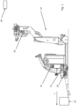
- Figure 1 shows an industrial truck 10 with a drive part 12.
- the industrial truck 10 is designed as a tractor without a load part.
- the industrial truck 10 also has a schematically illustrated vehicle control 16, a schematically illustrated transmitting and receiving unit 18 and a collision protection device 20.
- the collision protection device 20 is used to generate protective fields 22, 24 in the area around the industrial truck for the purpose of monitoring the environment for obstacles, as later will still be explained.
- the industrial truck 10 is in contact with a schematically illustrated higher-level control unit 40 via the transmitting and receiving unit 18.
- the higher-level control unit 40 can be, for example, a central warehouse management system.
- An obstacle 30 can also be seen, which lies in front of the industrial truck 10 in a direction of travel F. If the industrial truck 10 approaches the obstacle 30, this occurs in front of the industrial truck lying first protective field 22, whereupon the vehicle control 16 initiates a braking process of the industrial truck.
- the higher-level control unit 40 sends a travel order to the industrial truck 10, which receives it via the transmitting and receiving unit 18 and passes it on to the vehicle control 16. Based on the driving order, the vehicle control 16 controls the industrial truck 10 through a warehouse or production hall. The industrial truck 10 goes through several successive driving situations. At regular intervals, the industrial truck 10 sends its position within the driving order, i.e. within the distance to be traveled due to the driving order, to the higher-level control unit 40. The higher-level control unit 40 determines the next upcoming driving situation based on the driving order and based on the current position of the industrial truck 10 sends the industrial truck 10 a control command to set the protective field generated by the collision protection device 20.
- step 2a the industrial truck 10 is traveling straight ahead, with only a first protective field 22 arranged in front of the industrial truck being activated.
- step 2b the industrial truck 10 approaches a left turn, but is still traveling straight ahead. The driving situation now impending is therefore cornering.
- the higher-level control unit 40 now sends the industrial truck 10 the command to activate the protective field for cornering.
- the second protective field 24 is thus activated on the left side of the industrial truck 10, viewed in the direction of travel, and the curve to be traveled in the following is monitored.
- the first protective field 22 is enlarged.
- step 2c the industrial truck 10 now makes a 90° left turn with the protective fields 22, 24 activated.
- step 2d the industrial truck has 10 Straight-ahead travel has already been achieved again, but the second protective field 24 remains activated.
- the curve area can therefore continue to be monitored, which is particularly useful in the presence of trailers following the industrial truck, which may still be cornering at this point in time.
- step 2e the industrial truck is traveling straight ahead at a sufficient distance from the curve it is traveling through, whereupon the lateral protective field 24 is deactivated.
- the first protective field 22 was reduced again here.
- the first protective field 22 can be enlarged in particular by moving it forward in the direction of travel.
- a protective field sensor of the collision protection device can be tilted for this purpose, with the in Figure 1 The angle ⁇ shown is then reduced.
- the method according to the invention thus achieves predictive activation or adjustment of the protective fields, which leads to a particularly high level of collision safety and also allows driving through curves even at higher speeds.
Description
Die Erfindung betrifft ein Verfahren zur Steuerung eines Flurförderzeugs sowie ein System aus einer übergeordneten Steuereinheit und einem Flurförderzeug.The invention relates to a method for controlling an industrial truck and a system consisting of a higher-level control unit and an industrial truck.
Flurförderzeuge zum Transport von Lasten werden beispielsweise in Lager- oder Produktionshallen eingesetzt. Insbesondere bei autonom und automatisch fahrenden Flurförderzeugen ist das Flurförderzeug zumindest teilweise mit einem oder mehreren Schutzfeldern umgeben. Diese Schutzfelder werden von an dem Flurförderzeug angebrachten Sensoren erzeugt und decken flächige Bereiche beispielsweise in Fahrtrichtung vor dem Flurförderzeug ab. Bei Eintritt eines unbekannten Objekts, beispielsweise einer Person oder einem Gegenstand, in das Schutzfeld wird das Flurförderzeug gestoppt oder zunächst verlangsamt. Das Schutzfeld dient somit dem Kollisionsschutz.Industrial trucks for transporting loads are used, for example, in warehouses or production halls. In particular in the case of autonomous and automatically driving industrial trucks, the industrial truck is at least partially surrounded by one or more protective fields. These protective fields are generated by sensors attached to the industrial truck and cover flat areas, for example in the direction of travel in front of the industrial truck. If an unknown object, such as a person or an object, enters the protective field, the industrial truck is stopped or initially slowed down. The protective field therefore serves to protect against collisions.
Diese Schutzfelder sollten an die jeweils vorliegende Fahrsituation des Flurförderzeugs angepasst sein, um eine möglichst hohe Betriebssicherheit zu erreichen. So kann beispielsweise bei einer Kurvenfahrt des Flurförderzeugs in Abhängigkeit von dem durch das Flurförderzeug eingeschlagenen Lenkwinkel das Schutzfeld entsprechend der geänderten Fahrtrichtung positioniert werden. Auch kann das Schutzfeld in Abhängigkeit von der Geschwindigkeit des Flurförderzeugs sich unterschiedlich weit in Fahrtrichtung des Flurförderzeugs erstrecken. Der aktuelle Lenkwinkel bzw. die aktuelle Geschwindigkeit des Flurförderzeugs können hierbei über am Flurförderzeug vorgesehene Sensoren ermittelt werden. Insbesondere bei hohen Geschwindigkeiten oder bei engen Kurven kann es jedoch weiterhin zu Gefahrensituationen kommen.These protective fields should be adapted to the respective driving situation of the industrial truck in order to achieve the highest possible operational safety. For example, when the industrial truck is cornering, the protective field can be positioned in accordance with the changed direction of travel depending on the steering angle adopted by the industrial truck. The protective field can also extend to different distances in the direction of travel of the industrial truck depending on the speed of the industrial truck. The current steering angle or the current speed of the industrial truck can be determined using sensors provided on the industrial truck. However, dangerous situations can still occur, particularly at high speeds or on tight curves.
Ein System aus einer übergeordneten Steuereinheit und mehreren Flurförderzeugen ist aus
Aus
Der Erfindung liegt die Aufgabe zugrunde, ein Verfahren zur Steuerung eines Flurförderzeugs zur Verfügung zu stellen, die einen besseren Kollisionsschutz gewährleisten.The invention is based on the object of providing a method for controlling an industrial truck that ensures better collision protection.
Die Erfindung löst die Aufgabe durch ein Verfahren gemäß Anspruch 1.The invention solves the problem by a method according to claim 1.
Vorteilhafte Ausgestaltungen sind Gegenstand der Unteransprüche, der Beschreibung sowie der Figuren.Advantageous refinements are the subject of the subclaims, the description and the figures.
Das erfindungsgemäße Verfahren zur Steuerung mindestens eines Flurförderzeugs umfasst die Schritte: Bestimmen der Position des Flurförderzeugs innerhalb einer vorbekannten, durch das Flurförderzeug abzufahrenden Wegstrecke, Ermitteln einer bevorstehenden Fahrsituation in Abhängigkeit von der Position des Flurförderzeugs sowie in Abhängigkeit von einem von dem Flurförderzeug auszuführenden Fahrauftrag, Einstellen eines durch das Flurförderzeug überwachten Schutzfelds auf Grundlage der bevorstehenden Fahrsituation noch bevor das Flurförderzeug die Fahrsituation erreicht.The method according to the invention for controlling at least one industrial truck includes the steps: determining the position of the industrial truck within a previously known route to be traveled by the industrial truck, determining a upcoming driving situation depending on the position of the industrial truck and depending on a driving task to be carried out by the industrial truck, setting a protective field monitored by the industrial truck based on the upcoming driving situation even before the industrial truck reaches the driving situation.
Das mindestens eine Flurförderzeug kann beispielsweise ein Kommissionierfahrzeug sein. Auch kann das mindestens eine Flurförderzeug ein Schleppwagen eines Routenzugs sein, wobei der Schleppwagen über einen oder mehrere Anhänger verfügt. Insbesondere ist das Verfahren zur Steuerung mehrerer Flurförderzeuge in einer gemeinsamen Lager- oder Produktionshalle geeignet. Indem die Position des mindestens einen Flurförderzeugs innerhalb der aufgrund des Fahrauftrags abzufahrenden Wegstrecke bestimmt wird, kann ermittelt werden, welche Fahrsituation dem Flurförderzeug als nächstes bevorsteht. Eine solche Fahrsituation kann jegliche Situation sein, die eine Änderung des Betriebszustands des Flurförderzeugs erfordert, beispielsweise kann als Fahrsituation eine Kurvenfahrt oder eine Fahrt mit erhöhter Geschwindigkeit vorliegen. Erfindungsgemäß wird das Schutzfeld des Flurförderzeugs entsprechend der bevorstehenden Fahrsituation eingestellt. Einstellen bedeutet hierbei, dass ein bereits bestehendes Schutzfeld beispielsweise in seiner Größe und/oder in seiner Position verändert wird und/oder, dass ein noch nicht bestehendes Schutzfeld erzeugt wird. Das Schutzfeld kann insbesondere durch eine Kollisionsschutzeinrichtung des Flurförderzeugs erzeugt werden, wobei ein oder mehrere Sensoren zur Erzeugung des veränderten oder des erzeugten Schutzfeldes eingesetzt werden können. Wie eingangs erläutert, wird das Flurförderzeug bei Eintritt eines unbekannten Objekts, beispielsweise einer Person oder einem Gegenstand, in das Schutzfeld gestoppt bzw. verlangsamt, um Kollisionen zu verhindern. Erfindungsgemäß erfolgt eine vorausschauende Schutzfeldpositionierung noch bevor das Flurförderzeug in die jeweilige Fahrsituation eintritt. Das Schutzfeld wird nicht, wie eingangs erläutert, erst durch Änderung der Fahrsituation des Flurförderzeugs, also beispielsweise durch einen Lenkeinschlag, sondern bereits vor Eintritt dieser Situation angepasst. Hierdurch wird die Sicherheit erhöht, da Kollisionen umso zuverlässiger vermieden werden können. Insbesondere ermöglicht ein derartig vorausschauendes Fahren auch ein Betreiben des Flurförderzeugs bei höheren Geschwindigkeiten. So kann beispielsweise eine Kurve mit größerer Geschwindigkeit durchfahren werden. Somit kann die Umschlagsmenge erhöht und gleichzeitig eine besonders hohe Sicherheit für Personen, Flurförderzeug und Ladung gewährleistet werden. Der Fahrauftrag ist von einer übergeordneten Steuereinrichtung an das Flurförderzeug übermittelt und in einer Fahrzeugsteuerung hinterlegt worden.The at least one industrial truck can be, for example, a picking vehicle. The at least one industrial truck can also be a tow truck of a tugger train, with the tow truck having one or more trailers. The method is particularly suitable for controlling several industrial trucks in a common warehouse or production hall. By the position of the at least one industrial truck within the due to the When the distance to be traveled is determined based on the driving order, it can be determined which driving situation the industrial truck will face next. Such a driving situation can be any situation that requires a change in the operating state of the industrial truck; for example, the driving situation can be cornering or driving at increased speed. According to the invention, the protective field of the industrial truck is adjusted according to the upcoming driving situation. Setting here means that an already existing protective field is changed, for example in size and/or position, and/or that a protective field that does not yet exist is created. The protective field can in particular be generated by a collision protection device of the industrial truck, whereby one or more sensors can be used to generate the changed or generated protective field. As explained at the beginning, if an unknown object, for example a person or an object, enters the protective field, the industrial truck is stopped or slowed down in order to prevent collisions. According to the invention, a proactive protective field positioning takes place before the industrial truck enters the respective driving situation. The protective field is not, as explained at the beginning, only adjusted when the driving situation of the industrial truck changes, for example due to a steering angle, but rather before this situation occurs. This increases safety because collisions can be avoided more reliably. In particular, such forward-looking driving also enables the industrial truck to be operated at higher speeds. For example, a curve can be driven through at greater speed. This means that the handling volume can be increased and at the same time a particularly high level of safety for people, the truck and the load can be guaranteed. The driving order has been transmitted to the industrial truck by a higher-level control device and stored in a vehicle control system.
Nach einer Ausgestaltung wird die Position des Flurförderzeugs mittels einer übergeordneten Steuereinheit bestimmt, die bevorstehende Fahrsituation durch die übergeordnete Steuereinheit ermittelt und ein Stellbefehl durch die übergeordnete Steuereinheit zum Einstellen des Schutzfeldes an das Flurförderzeug gesendet. Die übergeordnete Steuereinheit ist von dem Flurförderzeug unabhängig ausgebildet, beispielsweise kann es sich um ein Lagerverwaltungssystem handeln. Die übergeordnete Steuereinheit ist dabei dazu ausgebildet, die Position des Flurförderzeugs innerhalb des Fahrauftrags, also innerhalb der aufgrund des Fahrauftrags abzufahrenden Wegstrecke, zu bestimmen. Das Flurförderzeug kann seine aktuelle Position beispielsweise an die Steuereinheit senden. Auch kann die aktuelle Position des Flurförderzeugs der übergeordneten Steuereinheit aufgrund des aktuellen Fahrauftrags des Flurförderzeugs bekannt sein. Die vorbekannte, durch das Flurförderzeug abzufahrende Wegstrecke kann als Teil des aktuellen Fahrauftrags in der übergeordneten Steuereinheit und/oder in dem Flurförderzeug hinterlegt sein. Dieser Fahrauftrag kann insbesondere durch die übergeordnete Steuereinheit an das mindestens eine Flurförderzeug gesendet werden. Nach dieser Ausgestaltung erfolgt also eine Koordination des Verfahrens durch die übergeordnete Steuereinheit. Die Steuereinheit, beispielsweise das Lagerverwaltungssystem, kann dabei insbesondere mehrere Flurförderzeuge koordinieren, die autonom fahren oder auch manuell gesteuert werden.According to one embodiment, the position of the industrial truck is determined by means of a higher-level control unit, the upcoming driving situation is determined by the higher-level control unit and an actuating command is sent to the industrial truck by the higher-level control unit to set the protective field. The higher-level control unit is designed to be independent of the industrial truck; for example, it can be a warehouse management system. The higher-level control unit is designed to determine the position of the industrial truck within the driving task, i.e. within the distance to be traveled due to the driving task. The industrial truck can send its current position to the control unit, for example. The current position of the industrial truck can also be known to the higher-level control unit based on the current travel order of the industrial truck. The previously known route to be traveled by the industrial truck can be stored as part of the current driving order in the higher-level control unit and/or in the industrial truck. This driving order can in particular be sent to the at least one industrial truck by the higher-level control unit. According to this configuration, the process is coordinated by the higher-level control unit. The control unit, for example the warehouse management system, can in particular coordinate several industrial trucks that drive autonomously or are also controlled manually.
Nach einer weiteren Ausgestaltung ist das mindestens eine Flurförderzeug ein automatisch oder autonom fahrendes Flurförderzeug. Das Flurförderzeug wird hierbei vollständig von einer übergeordneten Steuereinheit, beispielsweise einem zentralen Lagerverwaltungssystem, gesteuert. Gegenüber der vorherigen Ausgestaltung wird dann nicht (nur) das erfindungsgemäße Verfahren durch die übergeordnete Steuereinheit koordiniert, sondern das Flurförderzeug aufgrund von durch die übergeordnete Steuereinheit übermittelten Steuerbefehlen ohne Fahrer betrieben. Hierbei ist ein erfindungsgemäßes, vorrausschauendes Einstellen der Schutzfelder von besonderer Bedeutung, da im Notfall kein Fahrer eingreifen kann.According to a further embodiment, the at least one industrial truck is an automatically or autonomously driving industrial truck. The industrial truck is completely controlled by a higher-level control unit, for example a central warehouse management system. Compared to the previous embodiment, not (only) the method according to the invention is coordinated by the higher-level control unit, but the industrial truck is operated without a driver based on control commands transmitted by the higher-level control unit. Here, anticipatory setting of the protective fields according to the invention is of particular importance, since no driver can intervene in an emergency.
Nach einer Ausgestaltung ist die bevorstehende Fahrsituation eine Kurvenfahrt, wobei das Schutzfeld bereits vor Eintritt des Flurförderzeugs in die Kurvenfahrt in Richtung der Kurve positioniert wird. Wie bereits oben erwähnt, kann die bevorstehende Fahrsituation eine Kurvenfahrt sein. Im Gegensatz zu den eingangs beschriebenen Systemen erfolgt eine situationsadäquate Positionierung des Schutzfeldes jedoch nicht erst mit dem Lenkeinschlag des Flurförderzeugs sondern bereits vor Eintritt des Flurförderzeugs in die Kurvenfahrt, beispielsweise also bei einer zuvor erfolgenden Geradeausfahrt. Hierbei kann eine Positionierung des Schutzfeldes beispielsweise derart erfolgen, dass ein Schutzfeld in Richtung der Kurve in Fahrtrichtung seitlich vom Flurförderzeug aktiviert wird. Dieses seitliche Schutzfeld kann dabei insbesondere zusätzlich zu einem sich in Fahrtrichtung vor dem Flurförderzeug erstreckenden Schutzfeld geschaltet werden. Auch kann vorgesehen sein, dass sich ein in Fahrtrichtung vor dem Flurförderzeug erstreckendes Schutzfeld aufgrund des bevorstehenden Eintritts in die Kurvenfahrt in Richtung der zu fahrenden Kurve verschiebt oder verformt.According to one embodiment, the upcoming driving situation is a curve, with the protective field being positioned in the direction of the curve before the industrial truck enters the curve. As mentioned above, the upcoming driving situation may be cornering. In contrast to the systems described at the beginning, the situation-appropriate positioning of the protective field does not only take place when the truck is turned, but rather before the truck enters a curve, for example when driving straight ahead. Here, the protective field can be positioned, for example, in such a way that a protective field is activated in the direction of the curve in the direction of travel to the side of the industrial truck. This lateral protective field can in particular be switched in addition to a protective field extending in front of the industrial truck in the direction of travel. It can also be provided that a protective field extending in front of the industrial truck in the direction of travel shifts or deforms in the direction of the curve to be driven due to the imminent entry into the curve.
Nach einer weiteren Ausgestaltung ist die bevorstehende Fahrsituation eine Fahrt mit erhöhter Geschwindigkeit, wobei das Schutzfeld bereits vor Eintritt des Flurförderzeugs in die Fahrt mit erhöhter Geschwindigkeit einen größeren Bereich vor dem Flurförderzeug abdeckt oder in Fahrtrichtung nach vorne verlagert wird. Wie ebenfalls oben erwähnt, kann die Fahrsituation eine Fahrt mit erhöhter Geschwindigkeit sein. Im Gegensatz zu den bekannten Systemen wird jedoch nicht, beispielsweise über einen an einem Rad des Flurförderzeugs vorgesehenen Encoder, die Geschwindigkeit des Flurförderzeugs gemessen und davon abhängig das Schutzfeld positioniert. Stattdessen erfolgt erfindungsgemäß das Einstellen des Schutzfeldes bereits vorausschauend vor einer Beschleunigung des Flurförderzeugs. Das Schutzfeld wird dabei abhängig von der Geschwindigkeitsvorgabe für den bevorstehenden Streckenabschnitt der vorbekannten Wegstrecke erweitert, so dass es weiter vor das Flurförderzeug reicht. Auch kann das Schutzfeld in Fahrtrichtung des Flurförderzeugs weiter nach vorne verschoben werden, wobei sich auch hierbei die Größe des Schutzfelds ändern kann. Hierdurch wird erreicht, dass ein Hindernis, beispielsweise eine Person oder ein Objekt, bereits frühzeitig in das Schutzfeld eintritt und das Flurförderzeug somit frühzeitig einen Bremsvorgang einleiten kann.According to a further embodiment, the upcoming driving situation is a journey at increased speed, with the protective field covering a larger area in front of the industrial truck or being shifted forward in the direction of travel before the industrial truck enters the journey at increased speed. As also mentioned above, the driving situation can be driving at increased speed. In contrast to the known systems, however, the speed of the truck is not measured and the protective field is positioned depending on this, for example via an encoder provided on a wheel of the truck. Instead, according to the invention, the protective field is set in advance before the industrial truck accelerates. The protective field is expanded depending on the speed specification for the upcoming section of the previously known route, so that it extends further in front of the industrial truck. The protective field can also be moved further forward in the direction of travel of the industrial truck, whereby this too can change the size of the protective field. This ensures that an obstacle, for example a person or an object, enters the protective field at an early stage and the industrial truck can therefore initiate a braking process at an early stage.
Nach einer weiteren Ausgestaltung wird das überwachte Schutzfeld auch nach dem Verlassen der jeweiligen Fahrsituation weiter überwacht. Es kann folglich nicht nur, wie erfindungsgemäß vorgesehen, ein vorausschauendes Einstellen des Schutzfelds vorgesehen sein, sondern auch ein rückschauendes. So kann beispielsweise nach einer Kurvenfahrt des Flurförderzeugs weiterhin das Schutzfeld für die Kurvenfahrt für einen gewissen Zeitraum aktiviert bleiben, auch wenn das Flurförderzeug sich zumindest abschnittsweise wieder in einer Geradeausfahrt befindet. Dies ist insbesondere sinnvoll, wenn das Flurförderzeug ein Schleppwagen eines Routenzugs ist, wobei der Schleppwagen über mindestens einen Anhänger verfügt. Nach einer Ausgestaltung wird dann das überwachte Schutzfeld auch nach dem Verlassen der jeweiligen Fahrsituation durch den Schleppwagen weiter überwacht bis der mindestens eine Anhänger ebenfalls die jeweilige Fahrsituation verlassen hat. Hiermit kann berücksichtigt werden, dass insbesondere bei Routenzügen nach einer Kurvenfahrt der Schleppwagen sich häufig bereits wieder in der Geradeausfahrt befindet, während der oder die Anhänger noch die Kurve durchfahren. Insbesondere wenn die nachfolgenden Anhänger die durchfahrene Kurve schneiden, kann somit eine höhere Kollisionssicherheit erreicht werden.According to a further embodiment, the monitored protective field continues to be monitored even after leaving the respective driving situation. Consequently, not only a forward-looking setting of the protective field can be provided, as provided according to the invention, but also a retrospective setting. For example, after the truck has cornered, the protective field for cornering can remain activated for a certain period of time, even if the truck is at least partially traveling straight ahead again. This is particularly useful if the industrial truck is a tow truck of a tugger train, with the tow truck having at least one trailer. According to one embodiment, the monitored protective field is then further monitored by the towing vehicle even after the respective driving situation has been left until the at least one trailer has also left the respective driving situation. This can be taken into account that, especially in tugger trains, after cornering the tow truck is often already driving straight ahead again while the trailer or trailers are still driving through the curve. Particularly when the following trailers cut through the curve, greater collision safety can be achieved.
Nach einer weiteren Ausgestaltung wird der vom Flurförderzeug eingeschlagene Lenkwinkel überwacht und das Flurförderzeug gestoppt, wenn der Lenkwinkel einen durch den Fahrauftrag vorgegebenen Maximalwinkel überschreitet. Hierfür kann eine Sensoreinheit, beispielsweise ein Winkelencoder, zur Ermittlung des eingeschlagenen Lenkwinkels am Flurförderzeug vorgesehen sein. Der vorgegebene Maximalwert für den Lenkwinkel kann als Teil des Fahrauftrags insbesondere von einer übergeordneten Steuereinrichtung an das Flurförderzeug übermittelt worden sein. Der Fahrauftrag kann in einer Fahrzeugsteuerung hinterlegt sein. Die übergeordnete Steuereinheit oder die Fahrzeugsteuerung des Flurförderzeugs gleicht den aktuellen Lenkwinkel mit dem vorgegebenen Maximalwinkel ab. Überschreitet der vom Flurförderzeug eingeschlagene Lenkwinkel den Maximalwert, so wird durch die Kollisionsschutzeinrichtung das Flurförderzeug gestoppt. Es kann somit verhindert werden, dass das Flurförderzeug beim Einschlagen eines zu großen Lenkwinkels - beispielsweise aufgrund eines Fehlerfalls - eine Kollision verursacht.According to a further embodiment, the steering angle taken by the industrial truck is monitored and the industrial truck is stopped when the steering angle exceeds a maximum angle specified by the driving task. For this purpose, a sensor unit, for example an angle encoder, can be provided to determine the steering angle on the industrial truck. The specified maximum value for the steering angle may have been transmitted to the industrial truck as part of the driving task, in particular from a higher-level control device. The driving order can be stored in a vehicle control system. The The higher-level control unit or the vehicle control unit of the industrial truck compares the current steering angle with the specified maximum angle. If the steering angle taken by the truck exceeds the maximum value, the collision protection device stops the truck. It can thus be prevented that the industrial truck causes a collision when the steering angle is too large - for example due to an error.
Nach einer Ausgestaltung wird die vom Flurförderzeug eingeschlagene Lenkrichtung überwacht und das Flurförderzeug gestoppt, wenn die Lenkrichtung von einer durch den Fahrauftrag vorgegebenen Lenkrichtung abweicht. Auch hier kann entsprechend eine Sensoreinheit, beispielsweise ein Encoder, vorgesehen sein zur Überwachung der eingeschlagenen Lenkrichtung. Dieser Sensor kann insbesondere auch zur Überwachung des eingeschlagenen Lenkwinkels dienen, wie oben erwähnt. Die vorgegebene Lenkrichtung ergibt sich aus dem Fahrauftrag, der insbesondere von einer übergeordneten Steuereinrichtung an das Flurförderzeug übermittelt worden sein kann. Der Fahrauftrag kann, wie erläutert, in einer Fahrzeugsteuerung hinterlegt sein. Die übergeordnete Steuereinheit oder die Fahrzeugsteuerung des Flurförderzeugs gleicht die eingeschlagene Lenkrichtung mit der vorgegebenen Lenkrichtung ab. Sollte die eingeschlagene Lenkrichtung von der vorgegebenen Lenkrichtung abweichen, wird das Flurförderzeug gestoppt. Somit kann auch bei einer fehlerhaften Lenkung in eine nicht vorgesehene Richtung, beispielsweise nach rechts anstatt nach links, eine Kollision vermieden werden.According to one embodiment, the steering direction taken by the industrial truck is monitored and the industrial truck is stopped if the steering direction deviates from a steering direction specified by the driving task. Here too, a sensor unit, for example an encoder, can be provided to monitor the steering direction chosen. This sensor can also be used in particular to monitor the steering angle, as mentioned above. The specified steering direction results from the driving order, which may in particular have been transmitted to the industrial truck by a higher-level control device. As explained, the driving order can be stored in a vehicle control system. The higher-level control unit or the vehicle control of the industrial truck compares the chosen steering direction with the specified steering direction. If the chosen steering direction deviates from the specified steering direction, the truck will be stopped. This means that a collision can be avoided even if the steering is incorrect in an unintended direction, for example to the right instead of to the left.
Nach einer weiteren Ausgestaltung wird die vom Flurförderzeug eingenommene Geschwindigkeit überwacht und das Flurförderzeug gestoppt, wenn die Geschwindigkeit von einer durch den Fahrauftrag vorgegebenen Maximalgeschwindigkeit abweicht. Die Geschwindigkeit kann beispielsweise über einen an einem der Räder vorgesehenen Encoder ermittelt werden. Die vorgegebene Maximalgeschwindigkeit ergibt sich aus dem Fahrauftrag, der insbesondere von einer übergeordneten Steuereinrichtung an das Flurförderzeug übermittelt worden sein kann. Der Fahrauftrag kann, wie erläutert, in einer Fahrzeugsteuerung hinterlegt sein. Die übergeordnete Steuereinheit oder die Fahrzeugsteuerung des Flurförderzeugs gleicht die aktuelle Geschwindigkeit mit der Maximalgeschwindigkeit ab, wobei bei einem Überschreiten der Maximalgeschwindigkeit das Flurförderzeug gestoppt und somit die Kollisionssicherheit erhöht wird.According to a further embodiment, the speed adopted by the industrial truck is monitored and the industrial truck is stopped if the speed deviates from a maximum speed specified by the driving task. The speed can be determined, for example, via an encoder provided on one of the wheels. The specified maximum speed results from the travel order, which was transmitted to the industrial truck in particular by a higher-level control device can be. As explained, the driving order can be stored in a vehicle control system. The higher-level control unit or the vehicle control of the industrial truck compares the current speed with the maximum speed, whereby if the maximum speed is exceeded, the industrial truck is stopped and thus collision safety is increased.
Nach einer weiteren Ausgestaltung wird der vom Flurförderzeug eingeschlagene Lenkwinkel überwacht und das Schutzfeld bei einer Kurvenfahrt des Flurförderzeugs abhängig von einem diskreten Lenkwinkel positioniert. Das Schutzfeld für die Kurvenfahrt wird somit abhängig von dem Lenkwinkel eingestellt. Dies erfolgt jedoch nicht kontinuierlich, sondern diskret. Das Schutzfeld kann folglich mit zunehmendem Lenkwinkel in mehreren Stufen verstellt werden, beispielsweise können drei diskrete Lenkwinkel bei 30°, 60° und 90° vorgesehen sein, wobei bei einem Lenkwinkel von 30° das Schutzfeld in eine erste Position gestellt wird, bei einem Lenkwinkel von 60° das Schutzfeld in eine zweite Position gestellt wird und bei einem Lenkwinkel von 90° das Schutzfeld in eine dritte Position gestellt wird. Für jeden der Lenkwinkelbereiche kann ein Abgleich mit einem - beispielsweise durch den Fahrauftrag - vorgegebenen Lenkwinkel erfolgen und bei einer Abweichung ein Stoppen des Flurförderzeugs eingeleitet werden.According to a further embodiment, the steering angle adopted by the industrial truck is monitored and the protective field is positioned depending on a discrete steering angle when the industrial truck is cornering. The protective field for cornering is therefore set depending on the steering angle. However, this does not happen continuously, but discretely. The protective field can therefore be adjusted in several stages as the steering angle increases, for example three discrete steering angles can be provided at 30°, 60° and 90°, with the protective field being placed in a first position at a steering angle of 30°, at a steering angle of 60° the protective field is placed in a second position and at a steering angle of 90° the protective field is placed in a third position. For each of the steering angle ranges, a comparison can be made with a steering angle specified - for example by the driving task - and in the event of a deviation, the industrial truck can be stopped.
Das System umfasst eine übergeordnete Steuereinheit sowie mindestens ein Flurförderzeug, wobei die übergeordnete Steuereinheit dazu ausgebildet ist, die Position des Flurförderzeugs innerhalb einer vorbekannten, durch das Flurförderzeug abzufahrenden Wegstrecke zu bestimmen, eine bevorstehende Fahrsituation in Abhängigkeit von der Position des Flurförderzeugs sowie in Abhängigkeit von einem von dem Flurförderzeug auszuführenden Fahrauftrag zu ermitteln, sowie ein durch das Flurförderzeug überwachtes Schutzfeld auf Grundlage der bevorstehenden Fahrsituation einzustellen noch bevor das Flurförderzeug die Fahrsituation erreicht.The system includes a higher-level control unit and at least one industrial truck, the higher-level control unit being designed to determine the position of the industrial truck within a previously known route to be traveled by the industrial truck, an upcoming driving situation depending on the position of the industrial truck and depending on a to determine the driving order to be carried out by the industrial truck, and to set a protective field monitored by the industrial truck based on the upcoming driving situation before the industrial truck reaches the driving situation.
Das System ist zur Durchführung des erfindungsgemäßen Verfahrens geeignet. Insbesondere ist das mindestens eine Flurförderzeug ein autonom fahrendes Flurförderzeug.The system is suitable for carrying out the method according to the invention. In particular, the at least one industrial truck is an autonomously driving industrial truck.
Ein Ausführungsbeispiel der Erfindung wird im Folgenden anhand von Figuren erläutert. Es zeigen:
- Figur 1
- ein Flurförderzeug in einer seitlichen Ansicht, sowie
- Figur 2
- mehrere Ansichten des Flurförderzeugs aus
Figur 1 von oben während einer Kurvenfahrt.
- Figure 1
- an industrial truck in a side view, as well
- Figure 2
- several views of the industrial truck
Figure 1 from above while cornering.
Soweit nichts anderes angegeben ist, bezeichnen im Folgenden gleiche Bezugszeichen gleiche GegenständeUnless otherwise stated, the same reference numbers denote the same objects below
Die übergeordnete Steuereinheit 40 sendet einen Fahrauftrag an das Flurförderzeug 10, welches diesen über die Sende- und Empfangseinheit 18 empfängt und an die Fahrzeugsteuerung 16 weitergibt. Auf Grundlage des Fahrauftrags steuert die Fahrzeugsteuerung 16 das Flurförderzeug 10 durch eine Lager- oder Produktionshalle. Das Flurförderzeug 10 durchläuft hierbei mehrere aufeinanderfolgende Fahrsituationen. In regelmäßigen Abständen sendet das Flurförderzeug 10 seine Position innerhalb des Fahrauftrags, also innerhalb der aufgrund des Fahrauftrags abzufahrenden Wegstrecke, an die übergeordnete Steuereinheit 40. Die übergeordnete Steuereinheit 40 ermittelt aufgrund des Fahrauftrags sowie aufgrund der aktuellen Position des Flurförderzeugs 10 die als nächstes bevorstehende Fahrsituation und sendet dem Flurförderzeug 10 einen Steuerbefehl zum Einstellen des durch die Kollisionsschutzeinrichtung 20 erzeugten Schutzfelds.The higher-
Anhand von
Durch das erfindungsgemäße Verfahren wird somit ein vorausschauendes Aktivieren bzw. Anpassen der Schutzfelder erreicht, was zu einer besonders hohen Kollisionssicherheit führt und zudem eine Durchfahrt von Kurven auch bei höheren Geschwindigkeiten erlaubt.The method according to the invention thus achieves predictive activation or adjustment of the protective fields, which leads to a particularly high level of collision safety and also allows driving through curves even at higher speeds.
- 1010
- FlurförderzeugIndustrial truck
- 1212
- AntriebsteilDrive part
- 1616
- FahrzeugsteuerungVehicle control
- 1818
- Sende- und EmpfangseinheitTransmitting and receiving unit
- 2020
- KollisionsschutzvorrichtungCollision protection device
- 2222
- erstes Schutzfeldfirst protective field
- 2424
- zweites Schutzfeldsecond protective field
- 3030
- Hindernisobstacle
- 4040
- übergeordnete Steuereinheithigher-level control unit
Claims (11)
- A method for controlling at least one industrial truck, comprising the steps of- Determining the position of the industrial truck (10) within a previously known path to be driven by the industrial truck (10),- Identifying an impending driving situation depending on the position of the industrial truck (10) and depending on a driving task to be carried out by the industrial truck (10), wherein the driving task is transmitted to the industrial truck by a superordinate control apparatus and saved in a vehicle controller,- Setting a protective field (22, 24) monitored by the industrial truck (10) on the basis of the impending driving situation even before the industrial truck (10) reaches the driving situation.
- The method according to claim 1, characterized in that the position of the industrial truck (10) is determined by means of a superordinate control unit (40), the impending driving situation is identified by the superordinate control unit (40), and the superordinate control unit (40) sends a control command to the industrial truck to set the protective field (22, 24).
- The method according to claim 1 or 2, characterized in that the at least one industrial truck (10) is an autonomously or automatically driven industrial truck.
- The method according to one of the preceding claims, characterized in that the impending driving situation is driving in a curve, wherein the protective field (24) is positioned in the direction of the curve even before the industrial truck (10) begins driving into the curve.
- The method according to one of the preceding claims, characterized in that the impending driving situation is driving with increased speed, wherein the protective field covers a greater range in front of the industrial truck (10) or is displaced forward in the direction of travel even before the industrial truck (10) begins driving with increased speed.
- The method according to one of the preceding claims, characterized in that the monitored protective field (22, 24) continues to be monitored even after leaving the corresponding driving situation.
- The method according to claim 6, characterized in that the industrial truck (10) is a towing vehicle of a tugger train, wherein the towing vehicle has at least one trailer, wherein the monitored protective field (22, 24) continues to be monitored even after the towing vehicle has left the corresponding driving situation until the at least one trailer has also left the corresponding driving situation.
- The method according to one of the preceding claims, characterized in that the steering angle adopted by the industrial truck (10) is monitored and the industrial truck (10) is stopped when the adopted steering angle exceeds a maximum angle specified by the driving task.
- The method according to one of the preceding claims, characterized in that the steering direction adopted by the industrial truck (10) is monitored and the industrial truck (10) is stopped when the steering direction deviates from a steering direction specified by the driving task.
- The method according to one of the preceding claims, characterized in that the speed taken by the industrial truck is monitored and the industrial truck is stopped when the speed deviates from a maximum speed specified by the driving task.
- The method according to one of the preceding claims, characterized in that the steering angle adopted by the industrial truck (10) is monitored and the protective field (24) is positioned depending on a discrete steering angle when the industrial truck is driving in a curve.
Applications Claiming Priority (1)
| Application Number | Priority Date | Filing Date | Title |
|---|---|---|---|
| DE102018100758.2A DE102018100758A1 (en) | 2018-01-15 | 2018-01-15 | Method for controlling an industrial truck and a system comprising a higher-level control unit and a hoist |
Publications (2)
| Publication Number | Publication Date |
|---|---|
| EP3511289A1 EP3511289A1 (en) | 2019-07-17 |
| EP3511289B1 true EP3511289B1 (en) | 2023-12-20 |
Family
ID=65030960
Family Applications (1)
| Application Number | Title | Priority Date | Filing Date |
|---|---|---|---|
| EP19151788.7A Active EP3511289B1 (en) | 2018-01-15 | 2019-01-15 | Method for controlling an industrial truck and a system comprising a superordinate control unit and an industrial truck |
Country Status (4)
| Country | Link |
|---|---|
| US (1) | US11755011B2 (en) |
| EP (1) | EP3511289B1 (en) |
| CN (1) | CN110045728A (en) |
| DE (1) | DE102018100758A1 (en) |
Families Citing this family (4)
| Publication number | Priority date | Publication date | Assignee | Title |
|---|---|---|---|---|
| DE102019215180A1 (en) * | 2019-10-02 | 2021-04-08 | Robert Bosch Gmbh | Industrial truck, set up for driverless, autonomous operation for a load to be transported |
| DE102019216181A1 (en) * | 2019-10-21 | 2021-04-22 | Robert Bosch Gmbh | Industrial truck, set up for driverless, autonomous operation |
| DE102020117511A1 (en) * | 2020-07-02 | 2022-01-05 | Jungheinrich Aktiengesellschaft | Industrial truck with a jaw coupling, system consisting of an industrial truck and a trailer and a method for coupling a trailer to an industrial truck |
| DE102020213299A1 (en) * | 2020-10-21 | 2022-04-21 | Robert Bosch Gesellschaft mit beschränkter Haftung | Method for operating an at least partially automated industrial truck |
Family Cites Families (16)
| Publication number | Priority date | Publication date | Assignee | Title |
|---|---|---|---|---|
| DE4433786A1 (en) * | 1994-09-22 | 1996-03-28 | Mueller Peter Dr | Driverless vehicle obstacle recognition system, esp. for unmanned transport vehicle |
| DE10146465B4 (en) * | 2001-09-20 | 2011-07-07 | Götting jun., Hans-Heinrich, 31275 | transport vehicle |
| US7124027B1 (en) * | 2002-07-11 | 2006-10-17 | Yazaki North America, Inc. | Vehicular collision avoidance system |
| WO2006054678A1 (en) * | 2004-11-19 | 2006-05-26 | Mitsubishi Heavy Industries, Ltd. | Overturning prevention device for forklift truck |
| DE102005054359A1 (en) * | 2005-11-15 | 2007-05-16 | Leuze Lumiflex Gmbh & Co Kg | guard |
| US8346468B2 (en) | 2008-07-08 | 2013-01-01 | Sky-Trax Incorporated | Method and apparatus for collision avoidance |
| DE102009047264A1 (en) * | 2009-11-30 | 2011-06-01 | Robert Bosch Gmbh | Method for support of driver of vehicle, involves determining environment of vehicle and determining prospective driving direction at branching, crossing or curve by evaluation of driven trajectory |
| DE102010028911A1 (en) * | 2010-05-12 | 2011-11-17 | Robert Bosch Gmbh | Method for monitoring movement of vehicle i.e. fork lift lorry, involves detecting collision hazard of vehicle by obstruction placed in region of curved travel path, or leaving curved travel path by vehicle |
| US9230419B2 (en) * | 2010-07-27 | 2016-01-05 | Rite-Hite Holding Corporation | Methods and apparatus to detect and warn proximate entities of interest |
| DE102011016827B4 (en) * | 2011-04-12 | 2021-11-04 | Jungheinrich Aktiengesellschaft | Industrial truck with a holding brake and method for setting a holding torque on an industrial truck |
| EP2722687B1 (en) * | 2012-10-22 | 2015-04-29 | Sick Ag | Safety device for a vehicle |
| US20160180713A1 (en) * | 2014-12-18 | 2016-06-23 | Hand Held Products, Inc. | Collision-avoidance system and method |
| GB2538572B (en) * | 2015-05-18 | 2018-12-19 | Mobileye Vision Technologies Ltd | Safety system for a vehicle to detect and warn of a potential collision |
| US10304025B2 (en) * | 2015-05-26 | 2019-05-28 | Locanis Ag | Controlling industrial trucks in a warehouse |
| DE102015111613A1 (en) * | 2015-07-17 | 2017-01-19 | Still Gmbh | Method for detecting obstacles in an industrial truck |
| DE102015224309A1 (en) * | 2015-12-04 | 2017-06-08 | Kuka Roboter Gmbh | Representation of variable protective fields |
-
2018
- 2018-01-15 DE DE102018100758.2A patent/DE102018100758A1/en active Pending
-
2019
- 2019-01-15 US US16/247,905 patent/US11755011B2/en active Active
- 2019-01-15 CN CN201910033872.0A patent/CN110045728A/en active Pending
- 2019-01-15 EP EP19151788.7A patent/EP3511289B1/en active Active
Also Published As
| Publication number | Publication date |
|---|---|
| US11755011B2 (en) | 2023-09-12 |
| US20190220005A1 (en) | 2019-07-18 |
| DE102018100758A1 (en) | 2019-07-18 |
| CN110045728A (en) | 2019-07-23 |
| EP3511289A1 (en) | 2019-07-17 |
Similar Documents
| Publication | Publication Date | Title |
|---|---|---|
| EP3511289B1 (en) | Method for controlling an industrial truck and a system comprising a superordinate control unit and an industrial truck | |
| EP3663146B1 (en) | Driving assistance system for a motor vehicle, motor vehicle and method for operating a motor vehicle | |
| EP2234864B1 (en) | Driver assistance system and method for supporting the driver of a vehicle in maintaining a traffic lane limited by traffic lane markings | |
| EP3317162B1 (en) | Motor vehicle for piloted driving comprising a front axle steering system and a rear axle steering system | |
| EP3250426B1 (en) | Method and device for operating a vehicle | |
| EP0967121B1 (en) | Procedure and control device for minimizing the consequence of an accident. | |
| EP1516767B1 (en) | Method and device for controlling the speed of a vehicle, during manoeuvring and/or parking | |
| EP3322625B1 (en) | Anticipatory control system of a motor vehicle | |
| EP3721308A1 (en) | Method for moving a line of vehicles based on a predefinable overall operating strategy associated with the line of vehicles | |
| DE102016218424B4 (en) | Driver assistance system | |
| DE102009028880A1 (en) | Driving direction stabilization system for vehicles | |
| EP3105092B1 (en) | Method for operating a vehicle system designed to perform at least partially automatic vehicle guidance, and motor vehicle | |
| EP1486400A2 (en) | Vehicle control system | |
| EP3365739B1 (en) | Method for driving a motor vehicle at least partially autonomously and motor vehicle | |
| EP3365879A1 (en) | Method and device for reducing the risk of a collision of a motor vehicle with an object | |
| DE102018202847A1 (en) | Method for operating a steering assistance system | |
| WO2014202309A1 (en) | Avoidance and braking assistant for motor vehicles | |
| DE102010045694A1 (en) | Method for preventing collision of e.g. motor car with obstacle during parking in tight parking lot, involves determining whether collision of vehicle is threatened in predeterminable period based on application of simulation evaluation | |
| DE102014215096A1 (en) | Method and device for autonomous maneuvering of a motor vehicle | |
| DE102018108276A1 (en) | Driving assistance system with lane change suggestion | |
| EP3368388B1 (en) | Method for manoeuvring a motor vehicle with movement of the motor vehicle into a detection position, driver assistance system and motor vehicle | |
| EP4096955B1 (en) | Method for operating an assistance system | |
| DE102015220644A1 (en) | Method and apparatus for determining whether a performance of one or more security actions to reduce a collision risk of a collision of a motor vehicle with an object must be controlled | |
| DE102022210165B3 (en) | Method for operating a motor vehicle | |
| EP3913455B1 (en) | Control of a vehicle via reference sensor data |
Legal Events
| Date | Code | Title | Description |
|---|---|---|---|
| PUAI | Public reference made under article 153(3) epc to a published international application that has entered the european phase |
Free format text: ORIGINAL CODE: 0009012 |
|
| STAA | Information on the status of an ep patent application or granted ep patent |
Free format text: STATUS: THE APPLICATION HAS BEEN PUBLISHED |
|
| AK | Designated contracting states |
Kind code of ref document: A1 Designated state(s): AL AT BE BG CH CY CZ DE DK EE ES FI FR GB GR HR HU IE IS IT LI LT LU LV MC MK MT NL NO PL PT RO RS SE SI SK SM TR |
|
| AX | Request for extension of the european patent |
Extension state: BA ME |
|
| STAA | Information on the status of an ep patent application or granted ep patent |
Free format text: STATUS: REQUEST FOR EXAMINATION WAS MADE |
|
| 17P | Request for examination filed |
Effective date: 20191223 |
|
| RBV | Designated contracting states (corrected) |
Designated state(s): AL AT BE BG CH CY CZ DE DK EE ES FI FR GB GR HR HU IE IS IT LI LT LU LV MC MK MT NL NO PL PT RO RS SE SI SK SM TR |
|
| STAA | Information on the status of an ep patent application or granted ep patent |
Free format text: STATUS: EXAMINATION IS IN PROGRESS |
|
| 17Q | First examination report despatched |
Effective date: 20210622 |
|
| GRAP | Despatch of communication of intention to grant a patent |
Free format text: ORIGINAL CODE: EPIDOSNIGR1 |
|
| STAA | Information on the status of an ep patent application or granted ep patent |
Free format text: STATUS: GRANT OF PATENT IS INTENDED |
|
| INTG | Intention to grant announced |
Effective date: 20230321 |
|
| GRAJ | Information related to disapproval of communication of intention to grant by the applicant or resumption of examination proceedings by the epo deleted |
Free format text: ORIGINAL CODE: EPIDOSDIGR1 |
|
| STAA | Information on the status of an ep patent application or granted ep patent |
Free format text: STATUS: EXAMINATION IS IN PROGRESS |
|
| GRAP | Despatch of communication of intention to grant a patent |
Free format text: ORIGINAL CODE: EPIDOSNIGR1 |
|
| STAA | Information on the status of an ep patent application or granted ep patent |
Free format text: STATUS: GRANT OF PATENT IS INTENDED |
|
| INTC | Intention to grant announced (deleted) | ||
| P01 | Opt-out of the competence of the unified patent court (upc) registered |
Effective date: 20230628 |
|
| INTG | Intention to grant announced |
Effective date: 20230725 |
|
| GRAS | Grant fee paid |
Free format text: ORIGINAL CODE: EPIDOSNIGR3 |
|
| GRAA | (expected) grant |
Free format text: ORIGINAL CODE: 0009210 |
|
| STAA | Information on the status of an ep patent application or granted ep patent |
Free format text: STATUS: THE PATENT HAS BEEN GRANTED |
|
| AK | Designated contracting states |
Kind code of ref document: B1 Designated state(s): AL AT BE BG CH CY CZ DE DK EE ES FI FR GB GR HR HU IE IS IT LI LT LU LV MC MK MT NL NO PL PT RO RS SE SI SK SM TR |
|
| REG | Reference to a national code |
Ref country code: GB Ref legal event code: FG4D Free format text: NOT ENGLISH |
|
| REG | Reference to a national code |
Ref country code: CH Ref legal event code: EP |
|
| REG | Reference to a national code |
Ref country code: DE Ref legal event code: R096 Ref document number: 502019010148 Country of ref document: DE |
|
| REG | Reference to a national code |
Ref country code: IE Ref legal event code: FG4D Free format text: LANGUAGE OF EP DOCUMENT: GERMAN |
|
| REG | Reference to a national code |
Ref country code: SE Ref legal event code: TRGR |
|
| PG25 | Lapsed in a contracting state [announced via postgrant information from national office to epo] |
Ref country code: GR Free format text: LAPSE BECAUSE OF FAILURE TO SUBMIT A TRANSLATION OF THE DESCRIPTION OR TO PAY THE FEE WITHIN THE PRESCRIBED TIME-LIMIT Effective date: 20240321 |
|
| REG | Reference to a national code |
Ref country code: LT Ref legal event code: MG9D |
|
| PG25 | Lapsed in a contracting state [announced via postgrant information from national office to epo] |
Ref country code: LT Free format text: LAPSE BECAUSE OF FAILURE TO SUBMIT A TRANSLATION OF THE DESCRIPTION OR TO PAY THE FEE WITHIN THE PRESCRIBED TIME-LIMIT Effective date: 20231220 |