EP3312129B1 - Hebevorrichtung für industrieanlage - Google Patents
Hebevorrichtung für industrieanlage Download PDFInfo
- Publication number
- EP3312129B1 EP3312129B1 EP16813777.6A EP16813777A EP3312129B1 EP 3312129 B1 EP3312129 B1 EP 3312129B1 EP 16813777 A EP16813777 A EP 16813777A EP 3312129 B1 EP3312129 B1 EP 3312129B1
- Authority
- EP
- European Patent Office
- Prior art keywords
- industrial equipment
- lifting device
- lifting
- bridge
- housing
- Prior art date
- Legal status (The legal status is an assumption and is not a legal conclusion. Google has not performed a legal analysis and makes no representation as to the accuracy of the status listed.)
- Active
Links
Images


Classifications
-
- B—PERFORMING OPERATIONS; TRANSPORTING
- B66—HOISTING; LIFTING; HAULING
- B66C—CRANES; LOAD-ENGAGING ELEMENTS OR DEVICES FOR CRANES, CAPSTANS, WINCHES, OR TACKLES
- B66C1/00—Load-engaging elements or devices attached to lifting or lowering gear of cranes or adapted for connection therewith for transmitting lifting forces to articles or groups of articles
- B66C1/10—Load-engaging elements or devices attached to lifting or lowering gear of cranes or adapted for connection therewith for transmitting lifting forces to articles or groups of articles by mechanical means
- B66C1/62—Load-engaging elements or devices attached to lifting or lowering gear of cranes or adapted for connection therewith for transmitting lifting forces to articles or groups of articles by mechanical means comprising article-engaging members of a shape complementary to that of the articles to be handled
- B66C1/66—Load-engaging elements or devices attached to lifting or lowering gear of cranes or adapted for connection therewith for transmitting lifting forces to articles or groups of articles by mechanical means comprising article-engaging members of a shape complementary to that of the articles to be handled for engaging holes, recesses, or abutments on articles specially provided for facilitating handling thereof
-
- B—PERFORMING OPERATIONS; TRANSPORTING
- B66—HOISTING; LIFTING; HAULING
- B66C—CRANES; LOAD-ENGAGING ELEMENTS OR DEVICES FOR CRANES, CAPSTANS, WINCHES, OR TACKLES
- B66C1/00—Load-engaging elements or devices attached to lifting or lowering gear of cranes or adapted for connection therewith for transmitting lifting forces to articles or groups of articles
- B66C1/10—Load-engaging elements or devices attached to lifting or lowering gear of cranes or adapted for connection therewith for transmitting lifting forces to articles or groups of articles by mechanical means
- B66C1/22—Rigid members, e.g. L-shaped members, with parts engaging the under surface of the loads; Crane hooks
- B66C1/34—Crane hooks
- B66C1/36—Crane hooks with means, e.g. spring-biased detents, for preventing inadvertent disengagement of loads
-
- B—PERFORMING OPERATIONS; TRANSPORTING
- B66—HOISTING; LIFTING; HAULING
- B66C—CRANES; LOAD-ENGAGING ELEMENTS OR DEVICES FOR CRANES, CAPSTANS, WINCHES, OR TACKLES
- B66C1/00—Load-engaging elements or devices attached to lifting or lowering gear of cranes or adapted for connection therewith for transmitting lifting forces to articles or groups of articles
- B66C1/10—Load-engaging elements or devices attached to lifting or lowering gear of cranes or adapted for connection therewith for transmitting lifting forces to articles or groups of articles by mechanical means
- B66C1/22—Rigid members, e.g. L-shaped members, with parts engaging the under surface of the loads; Crane hooks
- B66C1/34—Crane hooks
- B66C1/40—Crane hooks formed or fitted with load measuring or indicating devices
Definitions
- the present invention relates to a lifting device for industrial equipment, as an element to replace traditional hooks.
- the purpose of the invention is to provide a device which makes it possible to automate, weigh and remotely control the action of coupling and uncoupling equipment and similar items, which, with a conventional hook, it is necessary to perform manually.
- DE2728528 A discloses a lifting device consisting of an inverted U-shaped bridge with facing orifices through which passes a pin driven by a pneumatic piston.
- the device advocated makes it possible to automate, and control remotely, the action of coupling and uncoupling the equipment in question, which has lugs for lifting, in addition to offering additional features, such as being able to weigh the supported load.
- the device of the invention consists of a bridge or inverted U-shaped profile of considerable thickness, the arms of which have facing holes through which a pin passes.
- the space defined between the vertical arms of the "U” defines the zone for housing the lug of the equipment to be lifted, such that a mechanism for driving a pin is established laterally to the bridge.
- Said pin is driven by a pneumatic piston which is powered by a standalone compressor integrated into the device itself, where said mechanism is associated with a control circuit to actuate it via radio or manually by means of the corresponding safety push buttons placed on the device.
- a spring is provided and integrated into the pin which performs its shock absorbing effect with three main functions, to guarantee that the movement of the pneumatic piston is always complete, making it impossible for the pin to remain mid-travel between the two support points on the structural bridge.
- This spring can be replaced by ring-type shock absorbers or any other type of commercial shock absorber.
- This shock absorbing system also has the function of ensuring and aiding alignment of the bridge and the part to be coupled and to protect against faults due to impact by the pin, and as a system for thrust and alignment, both longitudinally and for support on the structural bridge, of said pin.
- a handlebar Arranged opposite the pin drive mechanism is provided a handlebar that allows for easy and convenient handling of the device if necessary.
- Solidly attached, emerging from the middle arm of the bridge is a suspension shaft with a load cell, such that said element passes through a housing in which the electronics for device control are housed.
- housed in said housing are electronic boards for safety management, Wi-Fi, Bluetooth, weighing machine management boards, radio emission and reception boards, compressor, pressure switch and other compressor protection systems, 24 W batteries, structural washers for load suspension, load cell, electrical connections, pneumatic connections, pneumatic solenoid valves and other elements necessary for proper operation of the device.
- the device includes a load safety system for closing and opening, with it being impossible to open said device if it is coupled to a suspended load.
- It also includes electrical systems for power control which register prohibited operations, giving rise to electrical blocking of the device, which is only reset by means of encrypted codes via radio.
- the device incorporates a "dead man" safety system, which prevents any risk of trapping. For operator safety and convenience, said operator will need to use both hands to actuate manual closure.
- the device includes indicator lights on its front to notify of open/closed states and battery status.
- the opening and closing mechanism has a high-performance, intelligent cushioning system.
- the device includes limit switches, and open and closed sensors, as well as load presence sensors.
- the equipment makes it possible to offer real-time weighing of the load by including strain gauges in the structural zones with maximum concentration of tensile stresses, such that the weighing signal obtained is sent to a remote control for viewing by the operator, although existing means can be used, such as mobile phones, tablets and similar, which communicate with the device by radio frequencies.
- the equipment has an electronic starter key to enable energy saving when not in use. Furthermore, the key can be coded, assigning a code that makes it possible to identify the operators responsible and download information relating to use, number of cycles, operations carried out, performance, etc.
- the device described is applicable to a wide range of existing cranes.
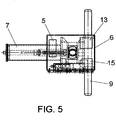
- figure 5 shows a plan view of the device in the previous figures.
- the device of the invention consists of an inverted U-shaped bridge (1), with facing orifices (2), through which a pin (3) passes, to block the corresponding lug of the equipment to be lifted, said pin (3), driven by a pneumatic piston (4), housed in the corresponding cylindrical housing (7), which is supplied by a standalone compressor (5) integrated in the device itself, specifically in a housing (6) arranged above the bridge (1), where said mechanism is associated with a control circuit for actuation thereof via radio or manually by means of the corresponding safety push buttons placed on the device.
- a spring (8) associated with the arm of the pneumatic piston (4) is integrated into the pin (3) which performs its shock absorbing effect with three main functions, to guarantee that the movement of the pneumatic piston is always complete, making it impossible for the pin to remain mid-travel between the two support points on the structural bridge.
- This spring can be replaced by ring-type shock absorbers or any other type of commercial shock absorber.
- This shock absorbing system also has the function of ensuring and aiding alignment of the bridge and the part to be coupled and to protect against faults due to impact by the pin, and a system for thrust and alignment, both longitudinally and for support on the structural bridge, of said pin.
- the bridge (1) Opposite the cylindrical housing (7), the bridge (1) has a handlebar (9) that provides for easy and convenient handling of the device if necessary.
- the bridge (1) is solidly connected at the upper end to a suspension shaft (10), with its corresponding lifting means (11), and integrated into which is a load cell (12), such that this element passes through the housing (6) in which the electronics for device control are housed.
- Housed in said housing (6) are at least one battery (12), one wireless communications module (13), and the control circuit (14) itself, in addition to the solenoid valves (15) to supply the pneumatic piston (4).
- the handlebar (9) includes a pair of push buttons (16) and (17) for the "dead man” system and for manual opening of the device.
- the device can be governed from the operator's own mobile phone, thanks to the wireless communications module, or it can have a remote control, which is not represented in the figures.
- the device includes indicator lamps (18, 19) which indicate open/closed and the battery status.
Landscapes
- Engineering & Computer Science (AREA)
- Mechanical Engineering (AREA)
- Load-Engaging Elements For Cranes (AREA)
- Selective Calling Equipment (AREA)
- Automatic Assembly (AREA)
- Forklifts And Lifting Vehicles (AREA)
Claims (11)
- Hebevorrichtung für Industrieanlagen, die aus einer umgekehrten U-Förmige Brücke (1) besteht und zum Heben von beliebigen, mit mindestens einer Hebeöse ausgestatteten Gegenständen dient,
mit gegenüberliegenden Öffnungen (2), durch die ein Stift (3) tritt, der von einem in einem entsprechenden zylindrischen Gehäuse (7) gelagerten pneumatischen Kolben (4) angetrieben wird, welcher von einem autark arbeitenden, in einem über der Brücke (1) angeordneten Gehäuse (6) befindlichen Kompressor (5) gespeist wird, wobei der genannte Mechanismus mit einer Steuerschaltung zu seiner Betätigung über Funk oder anhand der entsprechenden auf der Vorrichtung angeordneten Sicherheitsdrucktaster von Hand verbunden ist, mit dem besonderen Merkmal, dass die Oberseite der Brücke (1) fest mit einer Aufhängeachse (10) verbunden ist, welche mit entsprechenden Hebemitteln (11) versehen ist und eine integrierte Wägezelle (12) enthält, so dass die genannte Achse durch das Gehäuse (6), in dem die Elektronik zur Gerätesteuerung untergebracht ist, hindurch verläuft. - Hebevorrichtung für Industrieanlagen nach Anspruch 1, dadurch gekennzeichnet, dass eine mit der Stange des pneumatischen Kolbens (4) verbundene, als Stoßdämpfer dienende Feder (8) in den Stift (3) integriert ist.
- Hebevorrichtung für Industrieanlagen nach Anspruch 2, dadurch gekennzeichnet, dass die Feder (8) durch ringförmige Stoßdämpfer oder beliebige andere handelsübliche Stoßdämpfer ersetzt werden kann.
- Hebevorrichtung für Industrieanlagen nach Anspruch 1, dadurch gekennzeichnet, dass die Brücke (1) auf der dem zylindrischen Gehäuse (7) gegenüberliegenden Seite eine Griffstange (9) zur Handhabung der Vorrichtung aufweist.
- Hebevorrichtung für Industrieanlagen nach Anspruch 1, dadurch gekennzeichnet, dass im Inneren des Gehäuses (6) mindestens eine Batterie (12), ein Drahtloskommunikationsmodul (13) und die Steuerschaltung (14) selbst, nebst den Magnetventilen (15) zur Versorgung des Pneumatikkolbens (4), untergebracht sind.
- Hebevorrichtung für Industrieanlagen nach Anspruch 1, dadurch gekennzeichnet, dass die Griffstange (9) zwei Drucktaster (16) und (17), jeweils einen für die "Totmann"-Funktion und einen zum manuellen Öffnen der Vorrichtung, aufweist.
- Hebevorrichtung für Industrieanlagen nach Anspruch 1, dadurch gekennzeichnet, dass sie Kontrollleuchten (18-19) aufweist, die den offenen/geschlossenen Zustand und den Batteriestatus anzeigen.
- Hebevorrichtung für Industrieanlagen nach Anspruch 1, dadurch gekennzeichnet, dass sie ein Öffnungs- und Schließsystem zur Sicherung der Last umfasst, welches ein Öffnen der Vorrichtung bei angehängter Last unmöglich macht.
- Hebevorrichtung für Industrieanlagen nach Anspruch 1, dadurch gekennzeichnet, dass sie elektrische Systeme zur Leistungssteuerung umfasst, die unzulässige Vorgänge erfassen und eine elektrische Sperrung der Vorrichtung auslösen, die nur durch verschlüsselte Codes über Funk rücksetzbar ist.
- Hebevorrichtung für Industrieanlagen nach Anspruch 1, dadurch gekennzeichnet, dass sie Sensoren, wie beispielsweise Endschalter und Offen-/ Geschlossen-Sensoren, sowie Sensoren für das Vorhandensein von Lasten umfasst.
- Hebevorrichtung für Industrieanlagen nach Anspruch 1, dadurch gekennzeichnet, dass sie einen kodierbaren elektronischen Startschalter zur Energieeinsparung bei Nichtgebrauch enthält.
Priority Applications (1)
| Application Number | Priority Date | Filing Date | Title |
|---|---|---|---|
| PL16813777T PL3312129T3 (pl) | 2015-06-22 | 2016-04-26 | Urządzenie do podnoszenia sprzętu przemysłowego |
Applications Claiming Priority (2)
| Application Number | Priority Date | Filing Date | Title |
|---|---|---|---|
| ES201530883A ES2564878B1 (es) | 2015-06-22 | 2015-06-22 | Dispositivo de elevación de equipos industriales |
| PCT/ES2016/070306 WO2016207457A1 (es) | 2015-06-22 | 2016-04-26 | Dispositivo de elevacion de equipos industriales |
Publications (3)
| Publication Number | Publication Date |
|---|---|
| EP3312129A1 EP3312129A1 (de) | 2018-04-25 |
| EP3312129A4 EP3312129A4 (de) | 2019-02-20 |
| EP3312129B1 true EP3312129B1 (de) | 2020-06-17 |
Family
ID=55537248
Family Applications (1)
| Application Number | Title | Priority Date | Filing Date |
|---|---|---|---|
| EP16813777.6A Active EP3312129B1 (de) | 2015-06-22 | 2016-04-26 | Hebevorrichtung für industrieanlage |
Country Status (4)
| Country | Link |
|---|---|
| EP (1) | EP3312129B1 (de) |
| ES (1) | ES2564878B1 (de) |
| PL (1) | PL3312129T3 (de) |
| WO (1) | WO2016207457A1 (de) |
Family Cites Families (14)
| Publication number | Priority date | Publication date | Assignee | Title |
|---|---|---|---|---|
| GB736525A (en) * | 1953-01-16 | 1955-09-07 | Fawcett Preston & Co Ltd | Improvements in or relating to load indicators and/or maximum load safety apparatus |
| GB903828A (en) * | 1959-12-21 | 1962-08-22 | British Steel Piling Co Ltd | Improvements in or relating to shackles |
| DE2728528A1 (de) * | 1977-06-24 | 1979-01-11 | Hubert Etter | Lastaufnahmevorrichtung an einem hebezeug |
| US4216987A (en) * | 1978-10-26 | 1980-08-12 | Ely Robert G | Safety shackle |
| US4573725A (en) * | 1984-04-02 | 1986-03-04 | Griffiths Edward E | Remote controlled crane hook coupler |
| NO300587B1 (no) * | 1995-06-08 | 1997-06-23 | Balmoral Norge As | Hydraulisk sjakkel |
| NO964723L (no) * | 1996-11-07 | 1998-05-08 | Selantic As | Invertert akkumulator |
| KR100261406B1 (ko) * | 1997-10-23 | 2000-07-01 | 김재영 | 자동개폐형전동훅 |
| US6303882B1 (en) * | 2000-03-10 | 2001-10-16 | Cranium Corporation | Load cell apparatus and method |
| KR100631434B1 (ko) * | 2005-10-18 | 2006-10-09 | 황인규 | 자동 개폐형 샤클 조립체 |
| US8240728B2 (en) * | 2008-12-24 | 2012-08-14 | P&H Co., Ltd | Automated shackle assembly |
| EP2487103A1 (de) * | 2011-02-14 | 2012-08-15 | Selantic AS | Aktuatorvorrichtung |
| NO334555B1 (no) * | 2011-11-25 | 2014-04-07 | Lars Skjold | Undervannssjakkel for tung laster |
| US9000311B1 (en) * | 2013-01-09 | 2015-04-07 | Jeff L. Collins | Crane scale anti-torque and protection housing |
-
2015
- 2015-06-22 ES ES201530883A patent/ES2564878B1/es active Active
-
2016
- 2016-04-26 EP EP16813777.6A patent/EP3312129B1/de active Active
- 2016-04-26 WO PCT/ES2016/070306 patent/WO2016207457A1/es not_active Ceased
- 2016-04-26 PL PL16813777T patent/PL3312129T3/pl unknown
Non-Patent Citations (1)
| Title |
|---|
| None * |
Also Published As
| Publication number | Publication date |
|---|---|
| EP3312129A4 (de) | 2019-02-20 |
| ES2564878A2 (es) | 2016-03-29 |
| ES2564878R1 (es) | 2017-02-02 |
| WO2016207457A1 (es) | 2016-12-29 |
| ES2564878B1 (es) | 2017-11-08 |
| EP3312129A1 (de) | 2018-04-25 |
| PL3312129T3 (pl) | 2021-01-11 |
Similar Documents
| Publication | Publication Date | Title |
|---|---|---|
| JP2012508354A5 (ja) | 弁位置表示器、弁の位置を判定する方法および弁位置表示システム | |
| CA2638325A1 (en) | Method and apparatus for providing diagnostics of a lifting magnet system | |
| US20160016764A1 (en) | Material lifting system and method | |
| CN109282643B (zh) | 镍铁电炉炉顶加料无人化系统及控制方法 | |
| EP3312129A1 (de) | Hebevorrichtung für industrieanlage | |
| JP4353426B2 (ja) | 産業ロボットの制御装置及び制御方法 | |
| CN101343023B (zh) | 一种塔吊安全综合保护装置 | |
| CN102719576A (zh) | 一种控制冶金炉渣处理的方法及系统 | |
| US11042129B2 (en) | Redundant wireless safety system for manufacturing environment | |
| KR101797144B1 (ko) | 안전장치를 구비한 크레인 후크 | |
| CN205114175U (zh) | 一种集装箱扭锁自动解锁装置 | |
| CN202175406U (zh) | 一种工件传输系统 | |
| CN104355200B (zh) | 一种用于输电线路铁塔升降装置的安全锁 | |
| CN218025058U (zh) | 一种用于煤矿单轨吊机车的单轨吊起吊梁 | |
| Sim et al. | The development of a robot hand for the automation of steel column construction | |
| CN204529183U (zh) | 无线高度报警限停装置 | |
| JP2021176670A (ja) | 移動式ピン引き装置 | |
| CN107127774B (zh) | 一种大型机械手夹子 | |
| KR101914529B1 (ko) | 타워 크레인 운용 제어 시스템 | |
| CN219906766U (zh) | 一种单轨吊遥控提升装置的电气遥控系统 | |
| CN201473125U (zh) | 用于起重设备的控制装置、起重设备 | |
| CN208327169U (zh) | 一种利用电磁吸盘的起重控制系统 | |
| GB1583567A (en) | Remotecontrolled safety hook assembly | |
| CN202837862U (zh) | 一种远端及本地端双向控制开关组件 | |
| CN121897778A (zh) | 用于旋转杆闸阀的能量隔离智能锁具及阀门开关监测方法 |
Legal Events
| Date | Code | Title | Description |
|---|---|---|---|
| STAA | Information on the status of an ep patent application or granted ep patent |
Free format text: STATUS: THE INTERNATIONAL PUBLICATION HAS BEEN MADE |
|
| PUAI | Public reference made under article 153(3) epc to a published international application that has entered the european phase |
Free format text: ORIGINAL CODE: 0009012 |
|
| STAA | Information on the status of an ep patent application or granted ep patent |
Free format text: STATUS: REQUEST FOR EXAMINATION WAS MADE |
|
| 17P | Request for examination filed |
Effective date: 20180122 |
|
| AK | Designated contracting states |
Kind code of ref document: A1 Designated state(s): AL AT BE BG CH CY CZ DE DK EE ES FI FR GB GR HR HU IE IS IT LI LT LU LV MC MK MT NL NO PL PT RO RS SE SI SK SM TR |
|
| AX | Request for extension of the european patent |
Extension state: BA ME |
|
| DAV | Request for validation of the european patent (deleted) | ||
| DAX | Request for extension of the european patent (deleted) | ||
| A4 | Supplementary search report drawn up and despatched |
Effective date: 20190123 |
|
| RIC1 | Information provided on ipc code assigned before grant |
Ipc: B66C 1/66 20060101ALI20190117BHEP Ipc: B66C 1/34 20060101ALI20190117BHEP Ipc: B66C 1/36 20060101ALI20190117BHEP Ipc: B66C 1/40 20060101AFI20190117BHEP |
|
| RIC1 | Information provided on ipc code assigned before grant |
Ipc: B66C 1/66 20060101ALI20191205BHEP Ipc: B66C 1/40 20060101AFI20191205BHEP Ipc: B66C 1/36 20060101ALI20191205BHEP Ipc: B66C 1/34 20060101ALI20191205BHEP |
|
| GRAP | Despatch of communication of intention to grant a patent |
Free format text: ORIGINAL CODE: EPIDOSNIGR1 |
|
| STAA | Information on the status of an ep patent application or granted ep patent |
Free format text: STATUS: GRANT OF PATENT IS INTENDED |
|
| INTG | Intention to grant announced |
Effective date: 20200113 |
|
| GRAS | Grant fee paid |
Free format text: ORIGINAL CODE: EPIDOSNIGR3 |
|
| GRAA | (expected) grant |
Free format text: ORIGINAL CODE: 0009210 |
|
| STAA | Information on the status of an ep patent application or granted ep patent |
Free format text: STATUS: THE PATENT HAS BEEN GRANTED |
|
| AK | Designated contracting states |
Kind code of ref document: B1 Designated state(s): AL AT BE BG CH CY CZ DE DK EE ES FI FR GB GR HR HU IE IS IT LI LT LU LV MC MK MT NL NO PL PT RO RS SE SI SK SM TR |
|
| REG | Reference to a national code |
Ref country code: GB Ref legal event code: FG4D |
|
| REG | Reference to a national code |
Ref country code: CH Ref legal event code: EP |
|
| REG | Reference to a national code |
Ref country code: IE Ref legal event code: FG4D |
|
| REG | Reference to a national code |
Ref country code: DE Ref legal event code: R096 Ref document number: 602016038399 Country of ref document: DE |
|
| REG | Reference to a national code |
Ref country code: AT Ref legal event code: REF Ref document number: 1281069 Country of ref document: AT Kind code of ref document: T Effective date: 20200715 |
|
| PG25 | Lapsed in a contracting state [announced via postgrant information from national office to epo] |
Ref country code: FI Free format text: LAPSE BECAUSE OF FAILURE TO SUBMIT A TRANSLATION OF THE DESCRIPTION OR TO PAY THE FEE WITHIN THE PRESCRIBED TIME-LIMIT Effective date: 20200617 Ref country code: SE Free format text: LAPSE BECAUSE OF FAILURE TO SUBMIT A TRANSLATION OF THE DESCRIPTION OR TO PAY THE FEE WITHIN THE PRESCRIBED TIME-LIMIT Effective date: 20200617 Ref country code: LT Free format text: LAPSE BECAUSE OF FAILURE TO SUBMIT A TRANSLATION OF THE DESCRIPTION OR TO PAY THE FEE WITHIN THE PRESCRIBED TIME-LIMIT Effective date: 20200617 Ref country code: NO Free format text: LAPSE BECAUSE OF FAILURE TO SUBMIT A TRANSLATION OF THE DESCRIPTION OR TO PAY THE FEE WITHIN THE PRESCRIBED TIME-LIMIT Effective date: 20200917 Ref country code: GR Free format text: LAPSE BECAUSE OF FAILURE TO SUBMIT A TRANSLATION OF THE DESCRIPTION OR TO PAY THE FEE WITHIN THE PRESCRIBED TIME-LIMIT Effective date: 20200918 |
|
| REG | Reference to a national code |
Ref country code: LT Ref legal event code: MG4D |
|
| REG | Reference to a national code |
Ref country code: NL Ref legal event code: MP Effective date: 20200617 |
|
| PG25 | Lapsed in a contracting state [announced via postgrant information from national office to epo] |
Ref country code: BG Free format text: LAPSE BECAUSE OF FAILURE TO SUBMIT A TRANSLATION OF THE DESCRIPTION OR TO PAY THE FEE WITHIN THE PRESCRIBED TIME-LIMIT Effective date: 20200917 Ref country code: RS Free format text: LAPSE BECAUSE OF FAILURE TO SUBMIT A TRANSLATION OF THE DESCRIPTION OR TO PAY THE FEE WITHIN THE PRESCRIBED TIME-LIMIT Effective date: 20200617 Ref country code: LV Free format text: LAPSE BECAUSE OF FAILURE TO SUBMIT A TRANSLATION OF THE DESCRIPTION OR TO PAY THE FEE WITHIN THE PRESCRIBED TIME-LIMIT Effective date: 20200617 Ref country code: HR Free format text: LAPSE BECAUSE OF FAILURE TO SUBMIT A TRANSLATION OF THE DESCRIPTION OR TO PAY THE FEE WITHIN THE PRESCRIBED TIME-LIMIT Effective date: 20200617 |
|
| REG | Reference to a national code |
Ref country code: AT Ref legal event code: MK05 Ref document number: 1281069 Country of ref document: AT Kind code of ref document: T Effective date: 20200617 |
|
| PG25 | Lapsed in a contracting state [announced via postgrant information from national office to epo] |
Ref country code: AL Free format text: LAPSE BECAUSE OF FAILURE TO SUBMIT A TRANSLATION OF THE DESCRIPTION OR TO PAY THE FEE WITHIN THE PRESCRIBED TIME-LIMIT Effective date: 20200617 Ref country code: NL Free format text: LAPSE BECAUSE OF FAILURE TO SUBMIT A TRANSLATION OF THE DESCRIPTION OR TO PAY THE FEE WITHIN THE PRESCRIBED TIME-LIMIT Effective date: 20200617 |
|
| PG25 | Lapsed in a contracting state [announced via postgrant information from national office to epo] |
Ref country code: AT Free format text: LAPSE BECAUSE OF FAILURE TO SUBMIT A TRANSLATION OF THE DESCRIPTION OR TO PAY THE FEE WITHIN THE PRESCRIBED TIME-LIMIT Effective date: 20200617 Ref country code: ES Free format text: LAPSE BECAUSE OF FAILURE TO SUBMIT A TRANSLATION OF THE DESCRIPTION OR TO PAY THE FEE WITHIN THE PRESCRIBED TIME-LIMIT Effective date: 20200617 Ref country code: SM Free format text: LAPSE BECAUSE OF FAILURE TO SUBMIT A TRANSLATION OF THE DESCRIPTION OR TO PAY THE FEE WITHIN THE PRESCRIBED TIME-LIMIT Effective date: 20200617 Ref country code: EE Free format text: LAPSE BECAUSE OF FAILURE TO SUBMIT A TRANSLATION OF THE DESCRIPTION OR TO PAY THE FEE WITHIN THE PRESCRIBED TIME-LIMIT Effective date: 20200617 Ref country code: IT Free format text: LAPSE BECAUSE OF FAILURE TO SUBMIT A TRANSLATION OF THE DESCRIPTION OR TO PAY THE FEE WITHIN THE PRESCRIBED TIME-LIMIT Effective date: 20200617 Ref country code: CZ Free format text: LAPSE BECAUSE OF FAILURE TO SUBMIT A TRANSLATION OF THE DESCRIPTION OR TO PAY THE FEE WITHIN THE PRESCRIBED TIME-LIMIT Effective date: 20200617 Ref country code: RO Free format text: LAPSE BECAUSE OF FAILURE TO SUBMIT A TRANSLATION OF THE DESCRIPTION OR TO PAY THE FEE WITHIN THE PRESCRIBED TIME-LIMIT Effective date: 20200617 Ref country code: PT Free format text: LAPSE BECAUSE OF FAILURE TO SUBMIT A TRANSLATION OF THE DESCRIPTION OR TO PAY THE FEE WITHIN THE PRESCRIBED TIME-LIMIT Effective date: 20201019 |
|
| PG25 | Lapsed in a contracting state [announced via postgrant information from national office to epo] |
Ref country code: SK Free format text: LAPSE BECAUSE OF FAILURE TO SUBMIT A TRANSLATION OF THE DESCRIPTION OR TO PAY THE FEE WITHIN THE PRESCRIBED TIME-LIMIT Effective date: 20200617 Ref country code: IS Free format text: LAPSE BECAUSE OF FAILURE TO SUBMIT A TRANSLATION OF THE DESCRIPTION OR TO PAY THE FEE WITHIN THE PRESCRIBED TIME-LIMIT Effective date: 20201017 |
|
| REG | Reference to a national code |
Ref country code: DE Ref legal event code: R097 Ref document number: 602016038399 Country of ref document: DE |
|
| PLBE | No opposition filed within time limit |
Free format text: ORIGINAL CODE: 0009261 |
|
| STAA | Information on the status of an ep patent application or granted ep patent |
Free format text: STATUS: NO OPPOSITION FILED WITHIN TIME LIMIT |
|
| PG25 | Lapsed in a contracting state [announced via postgrant information from national office to epo] |
Ref country code: DK Free format text: LAPSE BECAUSE OF FAILURE TO SUBMIT A TRANSLATION OF THE DESCRIPTION OR TO PAY THE FEE WITHIN THE PRESCRIBED TIME-LIMIT Effective date: 20200617 |
|
| 26N | No opposition filed |
Effective date: 20210318 |
|
| PG25 | Lapsed in a contracting state [announced via postgrant information from national office to epo] |
Ref country code: SI Free format text: LAPSE BECAUSE OF FAILURE TO SUBMIT A TRANSLATION OF THE DESCRIPTION OR TO PAY THE FEE WITHIN THE PRESCRIBED TIME-LIMIT Effective date: 20200617 |
|
| PG25 | Lapsed in a contracting state [announced via postgrant information from national office to epo] |
Ref country code: MC Free format text: LAPSE BECAUSE OF FAILURE TO SUBMIT A TRANSLATION OF THE DESCRIPTION OR TO PAY THE FEE WITHIN THE PRESCRIBED TIME-LIMIT Effective date: 20200617 |
|
| PG25 | Lapsed in a contracting state [announced via postgrant information from national office to epo] |
Ref country code: LU Free format text: LAPSE BECAUSE OF NON-PAYMENT OF DUE FEES Effective date: 20210426 |
|
| REG | Reference to a national code |
Ref country code: BE Ref legal event code: MM Effective date: 20210430 |
|
| PG25 | Lapsed in a contracting state [announced via postgrant information from national office to epo] |
Ref country code: CH Free format text: LAPSE BECAUSE OF NON-PAYMENT OF DUE FEES Effective date: 20210430 Ref country code: LI Free format text: LAPSE BECAUSE OF NON-PAYMENT OF DUE FEES Effective date: 20210430 |
|
| PG25 | Lapsed in a contracting state [announced via postgrant information from national office to epo] |
Ref country code: IE Free format text: LAPSE BECAUSE OF NON-PAYMENT OF DUE FEES Effective date: 20210426 |
|
| PG25 | Lapsed in a contracting state [announced via postgrant information from national office to epo] |
Ref country code: IS Free format text: LAPSE BECAUSE OF FAILURE TO SUBMIT A TRANSLATION OF THE DESCRIPTION OR TO PAY THE FEE WITHIN THE PRESCRIBED TIME-LIMIT Effective date: 20201017 |
|
| PG25 | Lapsed in a contracting state [announced via postgrant information from national office to epo] |
Ref country code: BE Free format text: LAPSE BECAUSE OF NON-PAYMENT OF DUE FEES Effective date: 20210430 |
|
| PG25 | Lapsed in a contracting state [announced via postgrant information from national office to epo] |
Ref country code: CY Free format text: LAPSE BECAUSE OF FAILURE TO SUBMIT A TRANSLATION OF THE DESCRIPTION OR TO PAY THE FEE WITHIN THE PRESCRIBED TIME-LIMIT Effective date: 20200617 |
|
| PG25 | Lapsed in a contracting state [announced via postgrant information from national office to epo] |
Ref country code: HU Free format text: LAPSE BECAUSE OF FAILURE TO SUBMIT A TRANSLATION OF THE DESCRIPTION OR TO PAY THE FEE WITHIN THE PRESCRIBED TIME-LIMIT; INVALID AB INITIO Effective date: 20160426 |
|
| PG25 | Lapsed in a contracting state [announced via postgrant information from national office to epo] |
Ref country code: MK Free format text: LAPSE BECAUSE OF FAILURE TO SUBMIT A TRANSLATION OF THE DESCRIPTION OR TO PAY THE FEE WITHIN THE PRESCRIBED TIME-LIMIT Effective date: 20200617 |
|
| PG25 | Lapsed in a contracting state [announced via postgrant information from national office to epo] |
Ref country code: TR Free format text: LAPSE BECAUSE OF FAILURE TO SUBMIT A TRANSLATION OF THE DESCRIPTION OR TO PAY THE FEE WITHIN THE PRESCRIBED TIME-LIMIT Effective date: 20200617 |
|
| PG25 | Lapsed in a contracting state [announced via postgrant information from national office to epo] |
Ref country code: MT Free format text: LAPSE BECAUSE OF FAILURE TO SUBMIT A TRANSLATION OF THE DESCRIPTION OR TO PAY THE FEE WITHIN THE PRESCRIBED TIME-LIMIT Effective date: 20200617 |
|
| PGFP | Annual fee paid to national office [announced via postgrant information from national office to epo] |
Ref country code: PL Payment date: 20250407 Year of fee payment: 10 Ref country code: DE Payment date: 20250429 Year of fee payment: 10 |
|
| PGFP | Annual fee paid to national office [announced via postgrant information from national office to epo] |
Ref country code: GB Payment date: 20250428 Year of fee payment: 10 |
|
| PGFP | Annual fee paid to national office [announced via postgrant information from national office to epo] |
Ref country code: FR Payment date: 20250425 Year of fee payment: 10 |