EP3311992B1 - Verfahren zur herstellung eines thermoplastischen strangprofils - Google Patents
Verfahren zur herstellung eines thermoplastischen strangprofils Download PDFInfo
- Publication number
- EP3311992B1 EP3311992B1 EP17196174.1A EP17196174A EP3311992B1 EP 3311992 B1 EP3311992 B1 EP 3311992B1 EP 17196174 A EP17196174 A EP 17196174A EP 3311992 B1 EP3311992 B1 EP 3311992B1
- Authority
- EP
- European Patent Office
- Prior art keywords
- profile
- coating
- core profile
- core
- thermoplastic
- Prior art date
- Legal status (The legal status is an assumption and is not a legal conclusion. Google has not performed a legal analysis and makes no representation as to the accuracy of the status listed.)
- Active
Links
Images



Classifications
-
- B—PERFORMING OPERATIONS; TRANSPORTING
- B29—WORKING OF PLASTICS; WORKING OF SUBSTANCES IN A PLASTIC STATE IN GENERAL
- B29C—SHAPING OR JOINING OF PLASTICS; SHAPING OF MATERIAL IN A PLASTIC STATE, NOT OTHERWISE PROVIDED FOR; AFTER-TREATMENT OF THE SHAPED PRODUCTS, e.g. REPAIRING
- B29C70/00—Shaping composites, i.e. plastics material comprising reinforcements, fillers or preformed parts, e.g. inserts
- B29C70/04—Shaping composites, i.e. plastics material comprising reinforcements, fillers or preformed parts, e.g. inserts comprising reinforcements only, e.g. self-reinforcing plastics
- B29C70/28—Shaping operations therefor
- B29C70/40—Shaping or impregnating by compression not applied
- B29C70/50—Shaping or impregnating by compression not applied for producing articles of indefinite length, e.g. prepregs, sheet moulding compounds [SMC] or cross moulding compounds [XMC]
- B29C70/52—Pultrusion, i.e. forming and compressing by continuously pulling through a die
- B29C70/521—Pultrusion, i.e. forming and compressing by continuously pulling through a die and impregnating the reinforcement before the die
Definitions
- the thermoplastic extruded profile is a rail profile that is arcuate in the axial direction for a sliding cover, preferably a sliding glass cover of a chest freezer, in particular a chest freezer, such as is found in supermarkets, for example.
- profiles of this type are generally produced from an unreinforced polymer using an extrusion process.
- a metal reinforcement element must be regularly inserted into the hollow chamber.
- the EP 0 752 306 A1 describes the production of fiber-reinforced polymer profiles using reactive pultrusion.
- the DE 10 2013 2222923 A1 discloses a fiber reinforced polymeric structural component for motor vehicles.
- the invention is based on the object of specifying a method with which the production of a thermoplastic extruded profile with high mechanical stability and at the same time good thermal insulation properties is possible.
- thermoplastic extruded profile in which endless fiber strands, which are embedded in a polymer matrix during the process, are pulled out of the tool.
- pultrusion processes are known in the prior art for the production of thermoset profiles.
- the materials used in the production of duroplastics are fluid and can therefore be easily processed using a pultrusion process.
- thermoplastic materials due to their high toughness, thermoplastic materials, which offer significant advantages over thermosets due to their subsequent processing options (weldable, plastically deformable, etc.) and their properties (toughness, recyclability, etc.), are fundamentally unsuitable for pultrusion.
- thermoplastic matrix of the core profile is expediently produced from low-viscosity monomers and/or reactive oligomers which are suitable for processing in a pultrusion and which are polymerized to form the thermoplastic during the reactive pultrusion.
- the oligomers are expediently composed of 2 to 100, for example 5 to 50, monomers.
- additives for example initiators, for example in the form of peroxides or other free-radical-forming compounds, and/or catalysts and/or activators, such as stabilizers and/or impact modifiers, can be added to the reactive pultrusion.
- initiators for example in the form of peroxides or other free-radical-forming compounds
- catalysts and/or activators such as stabilizers and/or impact modifiers
- stabilizers and/or impact modifiers can be added to the reactive pultrusion.
- additives for example initiators, for example in the form of peroxides or other free-radical-forming compounds, and/or catalysts and/or activators, such as stabilizers and/or impact modifiers, can be added to the reactive pultrusion.
- two or more different monomers and/or reactive oligomers are to be fed into the reactive pultrusion (e.g. polyester).
- monomers and/or reactive oligomers are to be fed into the reactive pultrusion (e.g. polyester).
- reactive pultrusion allows a very high proportion of fibers in the core profile, for example more than 60% by weight, in particular more than 80% by weight, of fibers, so that due to this high proportion of continuous fibers, a considerable increase in mechanical stability can be achieved, which For example, it is several times higher than that of unreinforced thermoplastic profiles.
- the endless reinforcing fibers preferably consist of glass and/or carbon fibers.
- the outer coating expediently has a maximum layer thickness of 5 mm, eg a maximum of 2 mm, possibly a maximum of 1 mm.
- the insertion of a metal reinforcement into the hollow chamber can preferably be dispensed with, so that the profile simultaneously has excellent thermal insulation properties with high mechanical performance. This is particularly important when the profile is used as a rail profile for a sliding glass cover of a freezer.
- the combination of the reactive pultrusion process with a coating of the core profile produced with it ensures that the high demands on the surface (e.g. high gloss, low tendency to soiling, haptics) in the mentioned application of the rail profile for a glass sliding lid of a chest freezer, in particular a chest freezer, are met despite the high Fiber content of the core profile can be met.
- the coating is expediently applied to the entire surface or else only in certain areas of the outer surface of the core profile.
- a full-surface application means that the coating completely encloses the core profile. This can be expedient if the entire outer surface of the core profile has to have the correspondingly high surface quality. However, if individual areas of the core profile are covered later in use (e.g.
- the coating covers at least 70%, for example at least 80%, preferably at least 90% of the outer surface of the apex.
- the thermoplastic matrix of the core profile is expediently designed as a polyamide (PA) matrix or polyacrylate matrix, in particular a PMMA matrix.
- PA polyamide
- PMMA polyacrylate matrix
- the corresponding monomers and/or reactive oligomers for the production of PA, in particular PA 6 or PA 12, or polyacrylate, in particular PMMA are fed to the reactive pultrusion.
- polyester eg polyethylene terephthalate (PET), in particular impact-resistant polyethylene terephthalate (PET-G), or polybutylene terephthalate (PBT), or thermoplastic polyurethanes (TPU).
- PET polyethylene terephthalate
- PET-G impact-resistant polyethylene terephthalate
- PBT polybutylene terephthalate
- TPU thermoplastic polyurethanes
- BPA bisphenol A
- PC polycarbonate
- polyesteramides or polyimides by means of reactive pultrusion is also within the scope of the invention.
- the coating is expediently produced from a polymer which adheres to the core profile and which preferably corresponds to the material of the thermoplastic matrix of the core profile.
- the coating is also expediently made of PA or, in the case of a PMMA matrix of the core profile, the coating is also made of PMMA.
- the same materials can be used for the coating as for the thermoplastic matrix of the core profile, i.e. in addition to polyacrylate (e.g. PMMA) or PA (e.g. PA6 or PA12), in particular polyester (e.g. PET, PET-G or PBT), polyurethanes (e.g. TPU) , BPA or PC.
- the coating may be produced from polyvinyl chloride (PVC), styrene-acrylonitriles (SAN), acrylonitrile-styrene-acrylic ester (ASA), polyesteramides or polyimides.
- PVC polyvinyl chloride
- SAN styrene-acrylonitriles
- ASA acrylonitrile-styrene-acrylic ester
- polyesteramides polyesteramides
- polyimides polyesteramides or polyimides.
- the outer coating prefferably be coextruded with the core profile.
- coextrusion also means the application of the coating to the freshly produced core profile by means of an extrusion immediately following the reactive pultrusion online, in which case the intermediate cooling of the core profile before the application of the coating is also within the scope of the invention.
- the core profile and the coating can be produced in a common tool in coextrusion.
- At least one functional element is formed solely from the coating.
- the scope of the invention also includes the partial formation of at least one functional element solely by coating material, while in this case the core profile also partially contributes to the geometric design of this element.
- the coating can be designed in some areas in the form of a support web on which the sliding lid rests and slides along during an opening or closing movement, or the functional element can also be used as an element for Be designed to limit the vertical play of the sliding cover and is preferably formed on the support web.
- the functional element can also be used as a receiving device, eg receiving groove, for example for an elastomeric sealing element or for a latching element for latching with another component.
- the functional element can be designed as a latching element for latching with a further component.
- the coating itself can also have one or more hollow chambers and/or form one or more hollow chambers together with the core profile.
- the contour of the at least one functional element for example the support web described, is formed by a cross-sectional area of the core profile.
- This area of the core profile can then be covered by a thin coating layer, for example with a layer thickness of at most 2 mm, in particular at most 1 mm.
- the layer thickness of the coating in a surface area of at least 50%, preferably at least 70%, of the surface of the core profile covered by the coating is expediently at most 2 mm, preferably at most 1 mm.
- the outer coating can also be applied to the core profile as a liquid and/or powder and then cured to form a lacquer layer.
- This has the advantage that no extruder is required to apply the coating.
- this method can also be used to apply low-viscosity coating materials.
- the coating it is also within the scope of the invention for the coating to be laminated onto the core profile as a film.
- a coating or film lamination is particularly advantageous if the thermoplastic matrix of the core profile is designed as a PA, PET (not impact-resistant) or PBT matrix in order to ensure a high adhesive force of the coating on the core profile. Lacquers based in particular on polyurethane resin, polyester resin or epoxy resin come into consideration as material for the lacquer layer.
- the coating is laminated on as a film, it can contain, for example, fluoropolymer and/or aluminum or consist of fluoropolymer and/or aluminum.
- the layer thickness of the coating is expediently at most 1 mm, for example at most 0.5 mm.
- core profile coating Acrylate eg PMMA PVC, SAN, ASA or acrylate
- PMMA PA eg PA6 PA
- wet paint powder paint or foil PET G PVC, SAN, ASA or acrylate
- PMMA PET (not impact resistant) PET liquid paint, powder paint or foil PBT PBT, wet paint, powder paint or foil
- the core profile which has a PA matrix (especially PA6 matrix), for example, with a coating made of e.g. PA (especially PA6), for example to coextrude it, and then coat the outside with a second coating , e.g. in the form of a wet or powder coating or a laminating film.
- a PA matrix especially PA6 matrix
- PA especially PA6
- a second coating e.g. in the form of a wet or powder coating or a laminating film.
- the second coating which is important for the color design, for example, can be made very thin.
- the formation of the second coating as a laminated aluminum foil can be advantageous.
- color pigments to be added to the material of the coating before it is applied to the core profile.
- Color pigments within the meaning of the invention also include white pigments, which ensure that the strand profile is given the "color" white, e.g. through the use of the white pigment titanium dioxide.
- colored profiles e.g. red, green or blue.
- this coloring is achieved, for example, by laminating a correspondingly colored film.
- the extruded profile produced is used as a rail profile, preferably with a symmetrical cross section, for a sliding cover, in particular a sliding glass cover, of a chest freezer.
- the core profile preferably represents the structural composition of the extruded profile, to which the coating is added.
- the cross-sectional area of the core profile including the cross-sectional area of any hollow chambers can be more than 60%, preferably more than 80% of the cross-sectional area of the extruded profile including hollow chamber(s).
- an arc shape is impressed on the extruded profile during or after the reactive pultrusion in the axial direction.
- the arc shape can be created using a suitably designed pultrusion tool or a bending process at the end of the manufacturing process, preferably online.
- This arc shape is essential for the mentioned use of the profile as a rail profile for a freezer.
- the corresponding arc can span an angle of at least 10°, in particular at least 20°.
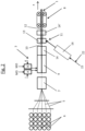
- the 1 shows a method according to the invention for producing a thermoplastic extruded profile 1.
- several hollow chambers 2, 2' cf. Fig. 3a-c ) Having extruded profile 1 produced using an extruded production process 3.
- endless reinforcing glass fibers 5 are integrated into the thermoplastic matrix 4 of the extruded profile 1, which are first drawn off from rollers 6 and preheated in a preheating station 7.
- the strand production process 3 is designed as a reactive pultrusion.
- the freshly produced extruded profile 1 is pulled out of the heated pultrusion tool 9 in the production direction x by means of a pulling tool 8 via the endless reinforcing fibers 5 .
- the reactive pultrusion 3 serves to produce an endless fiber-reinforced thermoplastic core profile 10 having several hollow chambers 2 (see also Fig. 3a-c , dyed black) of the extruded profile 1.
- the thermoplastic matrix 4 of this core profile is made from low-viscosity monomers and/or reactive oligomers—both denoted by MO—which are polymerized during the reactive pultrusion 3 to form the thermoplastic.
- initiators I and catalysts K are added to the reactive pultrusion 3 to guide the chemical reaction taking place therein.
- the monomers or oligomers denoted by MO are supplied in two components A and B to the reactive pultrusion for the purpose of polymerizing the thermoplastic.
- Component A contains mono-/oligomers MO and initiators I
- component B contains catalysts K in addition to the mono-/oligomers MO. This ensures that a reaction mixture containing mono-/oligomers MO as well as initiators I and catalysts K is only present in the pultrusion tool 9 and that the polymerization is therefore only started in the pultrusion tool 9 .
- the polymerization rate can also be controlled by heating the pultrusion tool 9 .
- the thermoplastic matrix 4 is in the form of a PA matrix, in particular a PA6 matrix.
- the core profile 10 produced with the reactive pultrusion 3 is provided with an outer coating 12, for example made of unreinforced PA, by means of a coextrusion 11 in order to improve the surface quality of the extruded profile 1.
- the coextrusion 11 takes place immediately after the reactive pultrusion 3 without intermediate cooling.
- the coextrusion tool 13 is arranged directly behind the outlet of the tool 9 for the reactive pultrusion 3 and encases the core profile 10 online. Only then is the coextruded extruded profile 1 cooled in a cooling device 14, for example a water bath.
- the reactive pultrusion 3 and the coextrusion 11 can also be carried out in a common tool.
- the core profile 10 is initially cooled in a cooling device 14.
- the thermoplastic matrix 4 of the core profile 10 is in turn designed as a PA matrix.
- the coextruded coating 12 also consists of PA material 15, which is supplied to an extruder 16 provided for the coextrusion 11, and thus from one on the Core profile 10 very well adhering polymer 15.
- the material 15 of the coating 12 corresponds in the exemplary embodiment to the material of the thermoplastic matrix 4 of the core profile 10.
- the extruded profile 1 is in a further cooling device 14 '(e.g. a water bath) finally cooled and calibrated. Furthermore, a further drawing tool (not shown) is optionally provided between the first cooling device 14 and the coextrusion 11 .
- the Figures 3a and 3b show a thermoplastic extruded profile 1 produced according to the invention, which, for example, can be combined with the 1 or 2 described method can be produced.
- the extruded profile 1 is designed as a rail profile for a sliding glass cover 50 of a freezer 100 (see Fig. 3c ), as found in supermarkets, for example.
- the enlarged cross section through the profile 1 in Figure 3b shows the reinforcing fibers 5 embedded in the thermoplastic matrix 4 of the core profile 10 and the coating 12 made of the coating material 15.
- the proportion by weight of the reinforcing fibers 5 in the core profile 10 is more than 80% in the exemplary embodiment.
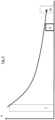
- the rail profile 1 has an arcuate shape in the axial direction, which was impressed on the rail profile during or after the reactive pultrusion 3 (not shown in detail).
- the angle ⁇ spanned by the circular segment-shaped rail profile 1 in the exemplary embodiment is more than 10°.
- the length L spanned by the profile 1 is more than 50 cm, for example more than 1 m
- Figure 3b it can be seen that the core profile 10 has an inner hollow chamber 2, which leads to weight and material savings and improved thermal insulation properties. Due to the high mechanical performance of the core profile 10, the insertion of a metallic reinforcement profile into the hollow chamber 2, which is regularly required in the prior art, is unnecessary in the exemplary embodiment.
- the rail profile 1 which is symmetrical in cross-section, also comprises functional elements 18 arranged one above the other on both sides in the form of support webs, on each of which a sliding glass cover 50 rests (in Figure 3b indicated on the right) and slides along during an opening or closing movement. Due to the multiple arrangement of the support webs 18 on top of each other, sliding lids 50 can be guided on top of each other on the rail profile 1 from both sides of the chest 100 (see Fig. Figure 3c ).
- FIG. 3b 1 also shows that the inner surface of the hollow chamber 2 is provided with ribs 25, preferably running in the axial direction of the extruded profile 1, which contribute to a further improvement in the mechanical stability of the extruded profile 1.
- the 3c shows several rail profiles 1 in the installed state as part of a chest freezer 100.
- the chest freezer 100 has a plurality of sliding covers 50 on both access sides a, b, which, by moving to the central plate 80 in the middle of the chest freezer 80, provide access to the (not shown) Allow refrigerated goods, eg deep-frozen food.
- the sliding covers 50 guided on the same rail profiles 1 must be arranged vertically offset from one another. This is made possible by the already described multiple arrangement of the support webs 18 one above the other.
- Extruded profiles 1 shown can be colored accordingly by adding color pigments 22 to the material 15 of the coating 12 before application to the core profile 10 .
- color pigments 22 can also be used in particular, which give the coating 12 a "real" color and lead to a red, green, blue, gray, yellow or black coloring of the extruded profile 1, for example.
- the outer coating it is not shown in the exemplary embodiments, but it is also possible within the scope of the invention for the outer coating to be applied to the core profile 10 as a liquid and/or powder and then to be cured to form a lacquer layer.
- a further advantage of the teaching according to the invention is that the profiles 1 produced with it only have a very low coefficient of thermal expansion. This benefit is in the figure 5 shown.
- the thermal expansion coefficients are shown on the y-axis, with the designations Nos. I., II. and III. each up refer to the same profiles as in 4 ..
- the thermal expansion of profiles 1 (II.) according to the invention is significantly lower than in the case of the unreinforced profile (I.)
- Even aluminum profiles (III.) have poorer performance here - i.e. a greater coefficient of expansion - than the profiles 1 produced according to the invention.
Landscapes
- Chemical & Material Sciences (AREA)
- Engineering & Computer Science (AREA)
- Composite Materials (AREA)
- Mechanical Engineering (AREA)
- Extrusion Moulding Of Plastics Or The Like (AREA)
Description
- Die Erfindung betrifft ein Verfahren zur Herstellung und Nutzung eines thermoplastischen Strangprofils,
- wobei das mindestens eine Hohlkammer aufweisende Strangprofil mit Hilfe eines Strangproduktionsprozesses hergestellt wird.
- Bei dem thermoplastischen Strangprofil handelt es sich erfindungsgemäß um ein in Achsrichtung bogenförmiges Schienenprofil für einen Schiebedeckel, vorzugsweise Glasschiebedeckel einer Kühltruhe, insbesondere Gefriertruhe, wie sie beispielsweise in Supermärkten anzutreffen ist. Gemäß dem Stand der Technik werden derartige Profile in der Regel mit einem Extrusionsverfahren aus einem unverstärkten Polymer hergestellt. Um jedoch bei den in diesen Anwendungsfällen großen Spannweiten der Profile eine ausreichende mechanische Festigkeit zu gewährleisten, muss in die Hohlkammer regelmäßig ein metallisches Armierungselement eingeschoben werden. Hierdurch wird zwar die mechanische Stabilität erheblich verbessert, dieser Vorteil muss jedoch wegen dem gleichzeitig als Wärmebrücke fungierenden metallischen Armierungsprofil mit deutlich schlechteren Wärmedämmeigenschaften erkauft werden. Aus der
US 6 029 411 A ist eine Schwingtür für Kühlschränke in Supermärkten bekannt, deren Rahmen mittels Pultrusion aus faserverstärktem Kunststoff hergestellt ist. DieUS 2014/109607 A1 offenbart ein Verfahren zur Herstellung und Nutzung eines Strangprofils mit einer Bogenform für einen Schiebedeckel einer Kühltruhe. - Die
EP 0 752 306 A1 beschreibt die Herstellung von faserverstärkten Polymerprofilen mittels reaktiver Pultrusion. - Die
DE 10 2013 2222923 A1 - Der Erfindung liegt die Aufgabe zugrunde, ein Verfahren anzugeben, mit dem die Herstellung eines thermoplastischen Strangprofils mit hoher mechanischer Stabilität und gleichzeitig guten Wärmedämmeigenschaften möglich ist.
- Diese Aufgabe wird durch die Merkmalskombination des Anspruchs 1 gelöst. Erfindungsgemäß wird also zur Herstellung des thermoplastischen Strangprofils ein Pultrusionsverfahren eingesetzt, bei dem endlose Faserstränge, welche während der Verfahrens in eine Polymermatrix eingebettet werden, aus dem Werkzeug herausgezogen werden. Derartige Pultrusionsverfahren sind im Stand der Technik bei der Herstellung von Duroplast-Profilen bekannt. Die Einsatzstoffe zur Herstellung von Duroplasten sind dünnflüssig und können daher im Wege eines Pultrusionsverfahrens gut verarbeitet werden. Aufgrund ihrer hohen Zähigkeit sind hingegen thermoplastische Materialien, welche aufgrund ihrer nachträglichen Bearbeitungsmöglichkeiten (schweißbar, plastisch verformbar etc.) und ihrer Eigenschaften (Zähigkeit, Recyclingfähigkeit etc.) wesentliche Vorteile gegenüber Duroplasten bieten, für eine Pultrusion grundsätzlich nicht geeignet. Im Rahmen der Erfindung wird nun jedoch die chemische Herstellung des Thermoplasten erst im eigentlichen Pultrusionsprozess durch die Zufuhr entsprechender Monomere durchgeführt, also in Form einer reaktiven Pultrusion. Zweckmäßigerweise wird die thermoplastische Matrix des Kernprofils hierbei aus dünnflüssigen, für die Verarbeitung in einer Pultrusion geeigneten Monomeren und/oder reaktiven Oligomeren hergestellt, die während der reaktiven Pultrusion zum Thermoplast polymerisiert werden. Zweckmäßigerweise sind die Oligomere jeweils aus 2 bis 100, z.B. 5 bis 50 Monomeren zusammengesetzt. Bei Bedarf können der reaktiven Pultrusion Zusatzstoffe, z.B. Initiatoren, beispielsweise in Form von Peroxiden oder anderen Radikale bildenden Verbindungen, und/oder Katalysatoren und/oder Aktivatoren, wie z.B. Stabilisatoren und/oder Schlagzäh-Modifier, zugegeben werden. Je nach herzustellendem Thermoplast sind der reaktiven Pultrusion zwei oder mehr verschiedene Monomere und/oder reaktive Oligomere zuzuführen (Bsp. Polyester). Im Rahmen der Erfindung liegt es aber auch, dass zur Polymerisation lediglich ein Monomer bzw. sich lediglich durch die Kettenlänge unterscheidende Oligomere eingesetzt werden (Bsp. PMMA). Die reaktive Pultrusion erlaubt insgesamt einen sehr hohen Faseranteil im Kernprofil, beispielsweise mehr als 60 Gew.-%, insbesondere mehr als 80 Gew.-% Faseranteil, so dass aufgrund dieses hohen Anteils an Endlosfasern eine beträchtliche Erhöhung der mechanischen Stabilität erzielt werden kann, welche beispielsweise um ein Mehrfaches höher ist als bei unverstärkten Thermoplast-Profilen. Die endlosen Verstärkungsfasern bestehen vorzugsweise aus Glas- und/oder Carbonfasern. Die äußere Beschichtung hat zweckmäßigerweise eine Schichtdicke von maximal 5 mm, z.B. maximal 2 mm, ggf. maximal 1 mm. Aufgrund der hohen mechanischen Festigkeit kann beim erfindungsgemäß hergestellten Profil vorzugsweise auf das Einschieben einer Metallarmierung in die Hohlkammer verzichtet werden, so dass das Profil bei hoher mechanischer Performance gleichzeitig exzellente Wärmedämmeigenschaften aufweist. Dies ist insbesondere beim bevorzugten Einsatz des Profils als Schienenprofil für einen Glasschiebedeckel einer Kühltruhe von Bedeutung.
- Durch die Kombination des reaktiven Pultrusionsprozesses mit einer Beschichtung des damit hergestellten Kernprofils wird sichergestellt, dass die insbesondere im genannten Anwendungsfall des Schienenprofils für einen Glasschiebedeckel einer Kühltruhe, insbesondere Gefriertruhe, hohen Anforderungen an die Oberfläche (z.B. Hochglanz, geringe Verschmutzungsneigung, Haptik) trotz des hohen Faseranteils des Kernprofils erfüllt werden können. Zweckmäßigerweise ist die Beschichtung vollflächig oder aber auch lediglich bereichsweise auf die äußere Oberfläche des Kernprofils aufgetragen. Eine vollflächige Auftragung meint, dass die Beschichtung das Kernprofil lückenlos umschließt. Dies kann zweckmäßig sein, sofern die gesamte äußere Oberfläche des Kernprofils die entsprechend hohe Oberflächengüte aufweisen muss. Wenn jedoch einzelne Bereiche des Kernprofils im späteren Gebrauch (z.B. aufgrund einer gemeinsam von Beschichtung und Kernprofil gebildeten Hohlkammer) verdeckt bzw. aufgrund der Montage weiterer Bauteile nicht sichtbar oder nicht zugänglich sind, können diese Oberflächenbereiche des Kernprofils von der Beschichtung ausgespart werden. Vorzugsweise bedeckt die Beschichtung mindestens 70 %, z.B. mindestens 80 %, vorzugsweise mindestens 90 % der äußeren Oberfläche des Kernprofils.
- Zweckmäßigerweise wird die thermoplastische Matrix des Kernprofils als Polyamid(PA)-Matrix oder Polyacrylat-Matrix, insbesondere PMMA-Matrix, ausgebildet. In diesem Fall werden der reaktiven Pultrusion die entsprechenden Monomere und/oder reaktiven Oligomere zur Herstellung von PA, insbesondere PA 6 oder PA 12, bzw. Polyacrylat, insbesondere PMMA zugeführt. Die Herstellung anderer Materialien während der reaktiven Pultrusion, beispielsweise von Polyester, z.B. Polyethylenterephthalat (PET), insbesondere schlagzähem Polyethylenterephthalat (PET-G), oder Polybutylenterephthalat (PBT), oder thermoplastischen Polyurethanen (TPU) wird hierdurch jedoch nicht ausgeschlossen. Die Herstellung von Bisphenol A (BPA), Polycarbonat (PC), Polyesteramiden oder Polyimiden mittels der reaktiven Pultrusion liegt hier ebenfalls im Rahmen der Erfindung.
- Zweckmäßigerweise wird die Beschichtung aus einem auf dem Kernprofil haftenden Polymer hergestellt, welches vorzugsweise dem Material der thermoplastischen Matrix des Kernprofils entspricht. So wird beispielsweise bei der Ausbildung der thermoplastischen Matrix des Kernprofils als PA-Matrix zweckmäßigerweise die Beschichtung ebenfalls aus PA hergestellt oder bei einer PMMA-Matrix des Kernprofils die Beschichtung auch aus PMMA. Grundsätzlich kommen für die Beschichtung dieselben Materialien wie für die Thermoplast-Matrix des Kernprofils infrage, also neben Polyacrylat (z.B. PMMA) oder PA (z.B. PA6 oder PA12) insbesondere Polyester (z.B. PET, PET-G oder PBT), Polyurethane (z.B. TPU), BPA oder PC. Im Rahmen der Erfindung liegt es auch, dass die Beschichtung aus Polyvinylchlorid (PVC), Styrene-Acrylonitrilen (SAN), Acrylnitil-Styrol-Acrylester (ASA), Polyesteramiden oder Polyimiden hergestellt werden. Zweckmäßigerweise besteht die Beschichtung aus einem nicht faserverstärkten Material.
- Im Rahmen der Erfindung liegt es insbesondere, dass die äußere Beschichtung mit dem Kernprofil coextrudiert wird. Der Begriff Coextrusion meint in diesem Zusammenhang auch den Auftrag der Beschichtung auf das frisch hergestellte Kernprofil mittels einer unmittelbar an die reaktive Pultrusion online anschließenden Extrusion, wobei in diesem Fall auch die Zwischenkühlung des Kernprofils vor dem Auftrag der Beschichtung im Rahmen der Erfindung liegt. Alternativ hierzu können bei der Coextrusion das Kernprofil und die Beschichtung in einem gemeinsamen Werkzeug hergestellt werden.
- Insbesondere im Rahmen der Coextrusion ist es möglich, dass lediglich von der Beschichtung mindestens ein Funktionselement gebildet wird. Das heißt konkret, dass nur Beschichtungsmaterial für die Bildung des Funktionselementes herangezogen wird und das Kernprofil an der geometrischen Gestaltung dieses Funktionselementes nicht beteiligt ist. Im Rahmen der Erfindung liegt aber auch die partielle Bildung mindestens eines Funktionselementes lediglich durch Beschichtungsmaterial, während in diesem Fall auch das Kernprofil partiell zur geometrischen Gestaltung dieses Elementes beiträgt. So kann beispielsweise bei der Ausbildung des erfindungsgemäßen Strangprofils als Schienenprofil für einen Glasschiebedeckel einer Kühltruhe die Beschichtung bereichsweise in Form eines Auflagestegs ausgebildet sein, auf dem der Schiebedeckel aufliegt und während einer Öffnungs- bzw. Schließbewegung entlang gleitet, oder das Funktionselement kann auch als Element zur Begrenzung des vertikalen Spiels des Schiebedeckels ausgebildet sein und ist vorzugsweise an den Auflagesteg angeformt. Das Funktionselement kann auch als Aufnahmevorrichtung, z.B. Aufnahmenut, beispielsweise für ein elastomeres Dichtungselement oder für ein Rastelement zum Verrasten mit einer weiteren Komponente ausgebildet werden. Ebenso kann das Funktionselement als Rastelement zum Verrasten mit einer weiteren Komponente ausgebildet sein. Ferner kann auch die Beschichtung selbst über eine oder mehrere Hohlkammern verfügen und/oder gemeinsam mit dem Kernprofil eine oder mehrere Hohlkammern bilden. Ebenso liegt es aber auch im Rahmen der Erfindung, dass die Kontur des mindestens einen Funktionselementes, z.B. des beschriebenen Auflagesteges, von einem Querschnittsbereich des Kernprofils gebildet wird. Dieser Bereich des Kernprofils kann dann von einer dünnen Beschichtungsauflage, beispielsweise mit einer Schichtdicke von höchstens 2 mm, insbesondere höchstens 1 mm, überzogen sein. Zweckmäßigerweise beträgt die Schichtdicke der Beschichtung in einem Oberflächenbereich von mindestens 50%, vorzugsweise mindestens 70 %, der von der Beschichtung bedeckten Oberfläche des Kernprofils höchstens 2 mm, vorzugsweise höchstens 1 mm. Alternativ zur Coextrusion kann die äußere Beschichtung jedoch auch als Flüssigkeit und / oder Pulver auf das Kernprofil aufgetragen und danach zu einer Lackschicht ausgehärtet werden. Dies hat den Vorteil, dass für die Auftragung der Beschichtung kein Extruder erforderlich ist. Insbesondere können mittels dieses Verfahrens auch dünnflüssige Beschichtungsmaterialien aufgetragen werden. Im Rahmen der Erfindung liegt es auch, dass die Beschichtung als Folie auf das Kernprofil aufkaschiert wird. Eine Lackierung bzw. Folienkaschierung ist insbesondere dann vorteilhaft, wenn dieThermoplast-Matrix des Kernprofils als PA-, PET(nicht schlagzäh)- oder PBT-Matrix ausgebildet wird, um hier eine große Haftkraft der Beschichtung auf dem Kernprofil sicherzustellen. Als Material für die Lackschicht kommen insbesondere auf Polyurethanharz, Polyesterharz oder Epoxidharz basierende Lacke infrage. Sofern die Beschichtung als Folie aufkaschiert wird, kann diese z.B. Fluorpolymer und/oder Aluminium enthalten bzw. aus Fluorpolymer und/oder Aluminium bestehen. Bei einer Beschichtung in Form einer Lackierung oder Folie beträgt die Schichtdicke der Beschichtung zweckmäßigerweise maximal 1 mm, z.B. maximal 0,5 mm.
- Insgesamt sind hinsichtlich des Materials des Kernprofils und der Beschaffenheit der Beschichtung insbesondere die folgenden Kombinationen vorteilhaft:
Kernprofil Beschichtung Acrylat, z.B. PMMA PVC, SAN, ASA oder Acrylat, z.B. PMMA PA, z.B. PA6 PA, Nasslack, Pulverlack oder Folie PET-G PVC, SAN, ASA oder Acrylat, z.B. PMMA PET (nicht schlagzäh) PET, Nasslack, Pulverlack oder Folie PBT PBT, Nasslack, Pulverlack oder Folie - Es kann auch zweckmäßig sein, das z.B. eine PA-Matrix (insbes. PA6-Matrix) aufweisende Kernprofil zunächst mit der Beschichtung aus z.B. PA (insbesondere. PA6) zu versehen, beispielsweise zu coextrudieren, und daran anschließend die Beschichtung außenseitig mit einer zweiten Beschichtung, z.B. in Form eines Nass- oder Pulverlacks bzw. einer Kaschierfolie, zu versehen. Dies hat den Vorteil, dass die Oberflächenglättung bereits durch die erste Beschichtung sichergestellt ist und somit die z.B. für die Farbgestaltung wesentliche zweite Beschichtung sehr dünn ausgebildet werden kann. So kann z.B. die Ausbildung der zweiten Beschichtung als kaschierte Aluminiumfolie vorteilhaft sein.
- Im Rahmen der Erfindung liegt es insbesondere, dass dem Material der Beschichtung vor dem Auftrag auf das Kernprofil Farbpigmente zugesetzt werden. Somit kann durch die Beschichtung auch das äußere Erscheinungsbild des Strangprofils maßgeblich beeinflusst werden. Farbpigmente im Sinne der Erfindung umfassen auch Weißpigmente, die dafür sorgen, dass das Strangprofil die "Farbe" Weiß erhält, z.B. durch den Einsatz des Weißpigmentes Titandioxid. Häufig besteht jedoch auch der Bedarf an farbigen, z.B. roten, grünen oder blauen Profilen. Diese Einfärbung wird im Stand der Technik z.B. durch die Aufkaschierung einer entsprechend eingefärbten Folie realisiert. Im Rahmen der Erfindung ist es nun möglich, die Farbgebung mittels des ohnehin vorzugsweise bereits vorgesehenen Auftrags einer Beschichtung durchzuführen. Sofern die Aufbringung der Beschichtung durch die vorbeschriebene Aufkaschierung einer Folie erfolgt, ist diese entsprechend eingefärbt.
- Wie bereits erwähnt, wird das hergestellte Strangprofil als, vorzugsweise im Querschnitt symmetrisches, Schienenprofil für einen Schiebedeckel, insbesondere einen Glasschiebedeckel, einer Kühltruhe verwendet. Vorzugsweise stellt das Kernprofil den strukturellen Aufbau des Strangprofils dar, welches um die Beschichtung ergänzt wird. So kann beispielsweise die Querschnittsfläche des Kernprofils incl. der Querschnittsfläche etwaiger Hohlkammern mehr als 60 %, vorzugweise mehr als 80 % der Querschnittsfläche des Strangprofils incl. Hohlkammer(n) betragen.
- Erfindungsgemäß wird dem Strangprofil während oder nach der reaktiven Pultrusion in Achsrichtung eine Bogenform aufgeprägt. Die Bogenform kann hierbei über ein entsprechend gestaltetes Pultrusionswerkzeug oder auch einen Biegeprozess am Ende des Herstellungsverfahrens, vorzugsweise online, erzeugt werden. Diese Bogenform ist für den genannten Einsatz des Profils als Schienenprofil für eine Kühltruhe wesentlich. Der entsprechende Bogen kann hierbei einen Winkel von mindestens 10°, insbesondere mindestens 20° überspannen.
- Im Folgenden wird die Erfindung anhand einer lediglich ein Ausführungsbeispiel darstellenden Zeichnung ausführlich erläutert. Es zeigen schematisch:
- Fig. 1
- ein erfindungsgemäßes Verfahren zur Herstellung eines Strangprofils;
- Fig. 2
- ein alternatives erfindungsgemäßes Herstellungsverfahren;
- Fig. 3a
- ein erfindungsgemäß, beispielsweise mit einem Verfahren gemäß
Fig.1 oder2 hergestelltes Strangprofil in einer Seitenansicht, - Fig. 3b
- den vergrößerten Schnitt A-A in
Fig. 3a , - Fig 3c
- das in den
Fig. 3a und 3b dargestellte Strangprofil im eingebauten Zustand und - Fig. 4, 5
- vergleichende Darstellungen hinsichtlich Steifigkeit und thermischem Ausdehnungskoeffizient der erfindungsgemäß hergestellten Profile gegenüber dem Stand der Technik.
- Die
Fig. 1 zeigt ein erfindungsgemäßes Verfahren zur Herstellung eines thermoplastischen Strangprofils 1. Bei diesem Verfahren wird das mehrere Hohlkammern 2, 2' (vergl.Fig. 3a-c ) aufweisende Strangprofil 1 mithilfe eines Strangproduktionsprozesses 3 hergestellt. Während dieses Strangproduktionsprozesses 3 werden in die thermoplastische Matrix 4 des Strangprofils 1 endlose Verstärkungsglasfasern 5 integriert, die zunächst von Rollen 6 abgezogen und in einer Vorwärmstation 7 vorgewärmt werden. Erfindungsgemäß ist der Strangproduktionsprozess 3 als reaktive Pultrusion ausgebildet. Hierbei wird mittels eines Ziehwerkzeugs 8 das frisch hergestellte Strangprofil 1 über die endlosen Verstärkungsfasern 5 in Produktionsrichtung x aus dem beheizten Pultrusionswerkzeug 9 herausgezogen. - Die reaktive Pultrusion 3 dient zur Herstellung eines endlos faserverstärkten, mehrere Hohlkammern 2 aufweisenden thermoplastischen Kernprofils 10 (s.a.
Fig. 3a-c , schwarz eingefärbt) des Strangprofils 1. Hierbei wird die thermoplastische Matrix 4 dieses Kernprofils aus dünnflüssigen Monomeren und/oder reaktiven Oligomeren - beide mit MO bezeichnet - hergestellt, die während der reaktiven Pultrusion 3 zum Thermoplast polymerisiert werden. Neben den Monomeren und/oder reaktvien Oligomeren MO werden der reaktiven Pultrusion 3 zur Führung der darin stattfindenden chemischen Reaktion Initiatoren I und Katalysatoren K zugesetzt. Im Ausführungsbeispiel werden zur Polymerisation des Thermoplasts die mit MO bezeichneten Monomere bzw. Oligomere in zwei Komponenten A und B der reaktiven Pultrusion zugeführt. Die Komponente A enthält Mono-/Oligomere MO sowie Initiatoren I, während die Komponente B neben den Mono-/Oligomeren MO Katalysatoren K enthält. Damit wird sichergestellt, dass erst im Pultrusionswerkzeug 9 ein Reaktionsgemisch enthaltend Mono-/Oligomere MO sowie Initiatoren I und Katalysatoren K vorliegt und somit die Polymerisation auch erst im Pultrusionswerkzeug 9 gestartet wird. Auch über die Beheizung des Pultrusionswerkzeugs 9 kann die Polymerisationsgeschwindigkeit gesteuert werden. Im Ausführungsbeispiel ist die thermoplastische Matrix 4 als PA-Matix, insbesondere PA6-Matrix ausgebildet. Das mit der reaktiven Pultrusion 3 hergestellte Kernprofil 10 wird zur Verbesserung der Oberflächengüte des Strangprofils 1 im Wege einer Coextrusion 11 mit einer äußeren Beschichtung 12, z.B. aus unverstärktem PA, versehen. Beim Ausführungsbeispiel gemäßFig. 1 findet die Coextrusion 11 unmittelbar im Anschluss an reaktive Pultrusion 3 ohne Zwischenkühlung statt. Hierbei ist das Coextrusionswerkzeug 13 unmittelbar hinter dem Austritt des Werkzeuges 9 für die reaktive Pultrusion 3 angeordnet und ummantelt das Kernprofil 10 online. Erst danach erfolgt die Abkühlung des coextrudierten Strangprofils 1 in einer Abkühlvorrichtung 14, z.B. einem Wasserbad. Alternativ hierzu können die reaktive Pultrusion 3 und die Coextrusion 11 auch in einem gemeinsamen Werkzeug durchgeführt werden. - Beim Ausführungsbeispiel gemäß
Fig. 2 hingegen erfolgt vor der ebenfalls online erfolgenden Coextrusion 11 der Beschichtung 12 zunächst in einer Abkühlvorrichtung 14 eine Zwischenkühlung des Kernprofils 10. Dies ist insbesondere bei der Coextrusion einer dicken Beschichtung 12 aufgrund des großen Wärmeeintrags sowie der Herstellung einer komplexen Kernprofilgeometrie von Vorteil, um diese vor der Coextrusion 11 zu stabilisieren. Die thermoplastische Matrix 4 des Kernprofils 10 wird wiederum als PA-Matrix ausgebildet. Die coextrudierte Beschichtung 12 besteht ebenfalls aus PA-Material 15, welches einem für die Coextrusion 11 vorgesehenen Extruder 16 zugeführt wird, und damit aus einem auf dem Kernprofil 10 sehr gut haftenden Polymer 15. Das Material 15 der Beschichtung 12 entspricht also im Ausführungsbeispiel dem Material der thermoplastischen Matrix 4 des Kernprofils 10. Nach der Coextrusion 11 der Beschichtung 12 wird das Strangprofil 1 in einer weiteren Abkühlvorrichtung 14' (z.B. einem Wasserbad) final abgekühlt und kalibriert. Ferner ist optional zwischen der ersten Abkühlvorrichtung 14 und der Coextrusion 11 eine weiteres Ziehwerkzeug vorgesehen (nicht dargestellt). - Die
Fig. 3a und 3b zeigen ein erfindungsgemäß hergestelltes thermoplastisches Strangprofil 1, welches beispielsweise mit den inFig. 1 oder2 beschriebenen Verfahren produziert werden kann. Im Ausführungsbeispiel ist das Strangprofil 1 als Schienenprofil für einen Glasschiebedeckel 50 einer Kühltruhe 100 ausgebildet (s.Fig. 3c ), wie sie beispielsweise in Supermärkten anzutreffen ist. Der vergrößerte Querschnitt durch das Profil 1 inFig. 3b zeigt die in die thermoplastische Matrix 4 des Kernprofils 10 eingebetteten Verstärkungsfasern 5 sowie die Beschichtung 12 aus dem Beschichtungsmaterial 15. Der Gewichtsanteil der Verstärkungsfasern 5 im Kernprofil 10 beträgt im Ausführungsbeispiel mehr als 80 %. DerFig. 3a ist zu entnehmen, dass das Schienenprofil 1 eine in Achsrichtung bogenförmige Gestalt aufweist, welche dem Schienenprofil während oder nach der reaktiven Pultrusion 3 aufgeprägt wurde (nicht näher dargestellt). Der vom im Ausführungsbeispiel kreissegmentfömigen Schienenprofil 1 hierbei überspannte Winkel α beträgt mehr als 10°. Die vom Profil 1 überspannte Länge L beträgt mehr als 50 cm, z.B. mehr als 1 m. Aus derFig. 3b ist ersichtlich, dass das Kernprofil 10 eine innere Hohlkammer 2 aufweist, welche zu einer Gewichts- und Materialeinsparung sowie zu verbesserten Wärmedämmeigenschaften führt. Aufgrund der hohen mechanischen Performance des Kernprofils 10 ist der im Stand der Technik regelmäßig erforderliche Einschub eines metallischen Armierungsprofils in die Hohlkammer 2 im Ausführungsbeispiel entbehrlich. Ferner ist erkennbar, dass die äußere Oberfläche des Kernprofils 10 von der Beschichtung 12 vollständig umschlossen ist. Das im Querschnitt symmetrische Schienenprofil 1 umfasst ferner an beiden Seiten übereinander angeordnete Funktionselemente 18 in Form von Auflagestegen, auf denen jeweils ein Glasschiebedeckel 50 aufliegt (inFig. 3b rechts angedeutet) und während einer Öffnungs- bzw. Schließbewegung entlang gleitet. Durch die mehrfache Anordnung der Auflagestege 18 übereinander können Schiebedeckel 50 von beiden Seiten der Truhe 100 übereinander auf dem Schienenprofil 1 geführt werden (s.Fig 3c ). An die Auflagestege 18 sind jeweils endseitig weitere Funktionselemente 18' in Form von vertikalen Vorsprüngen zur vertikalen Führung der Schiebedeckel 50 angeformt, wobei diese Vorsprünge 18' allein vom Material 15 der Beschichtung 12 gebildet werden. DieFig. 3b zeigt ferner, dass die innere Oberfläche der Hohlkammer 2 mit, vorzugsweise in Achsrichtung des Strangprofils 1 verlaufenden, Rippen 25 versehen ist, die zu einer weiteren Verbesserung der mechanischen Stabilität des Strangprofils 1 beitragen. DieFig. 3c zeigt mehrere Schienenprofile 1 im eingebauten Zustand als Bestandteil einer Kühltruhe 100. Die Kühltruhe 100 weist an beiden Zugriffsseiten a, b jeweils mehrere Schiebedeckel 50 auf, die durch eine Verfahrbewegung zur Zentralplatte 80 in der Mitte der Kühltruhe 80 einen Zugriff auf das (nicht dargestellte) Kühlgut, z.B. tiefgefrorene Lebensmittel, erlauben. Um gleichzeitig von beiden Seiten a, b den Zugriff zu ermöglichen, müssen die jeweils auf denselben Schienenprofilen 1 geführten Schiebedeckel 50 vertikal versetzt zueinander angeordnet sein. Dies wird durch die bereits beschriebene mehrfache Anordnung der Auflagestege 18 übereinander ermöglicht. - Die in
Fig. 3a bis 3c dargestellten Strangprofile 1 können durch den Zusatz von Farbpigmenten 22 zum Material 15 der Beschichtung 12 vor dem Auftrag auf das Kernprofil 10 entsprechend eingefärbt werden. Neben dem Einsatz klassischer Weißpigmente 22, z.B. Titandioxid, können insbesondere auch Farbpigmente 22 verwendet werden, die der Beschichtung 12 eine "echte" Farbe verleihen und z.B. zu einer roten, grünen, blauen, grauen, gelben oder auch schwarzen Einfärbung des Strangprofils 1 führen. In den Ausführungsbeispielen nicht dargestellt, jedoch im Rahmen der Erfindung ebenfalls möglich ist es, dass die äußere Beschichtung als Flüssigkeit und / oder Pulver auf das Kernprofil 10 aufgetragen und danach zu einer Lackschicht ausgehärtet wird. - Die nachfolgenden
Fig. 4 und5 zeigen die Performance erfindungsgemäß hergestellter Strangprofile 1 im Vergleich zum Stand der Technik. Es ist erkennbar, dass mit einem erfindungsgemäß hergestellten Strangprofil 1 (Ziffer II.) eine erheblich höhere mechanische Steifigkeit (y-Achse: E-Modul) erzielt werden kann als dies bei einem unverstärkten Profil (I.) möglich ist. Mit dem erfindungsgemäß hergestellten Profil 1 (II.) können annähernd mechanische Eigenschaften wie bei einem Aluminium-Gussprofil ohne thermische Trennung (III.) erzielt werden. Letzteres weist jedoch erheblich schlechtere Wärmedämmeigenschaften auf, ist sehr teuer und besitzt ein hohes Gewicht. - Ein weiterer Vorteil der erfindungsgemäßen Lehre liegt darin, dass die damit hergestellten Profile 1 nur einen sehr niedrigen Wärmeausdehnungskoeffizienten aufweisen. Dieser Vorteil ist in der
Fig. 5 dargestellt. Hier sind auf der y-Achse jeweils die thermischen Ausdehnungskoeffizienten dargestellt, wobei die Bezeichnungen Ziff. I., II. und III. sich jeweils auf dieselben Profile beziehen wie inFig. 4 .. Die Wärmeausdehnung erfindungsgemäßer Profile 1 (II.) ist deutlich niedriger als beim unverstärkten Profil (I.) Sogar Aluminiumprofile (III.) weisen hier eine schlechtere Performance - also einen größeren Ausdehnungskoeffizienten - auf als die erfindungsgemäß hergestellten Profile 1.
Claims (10)
- Verfahren zur Herstellung und Nutzung eines thermoplastischen Strangprofils (1),- wobei das mindestens eine Hohlkammer (2) aufweisende Strangprofil (1) mit Hilfe eines Strangproduktionsprozesses (3) hergestellt wird,- wobei während des Strangproduktionsprozesses (3) in die thermoplastische Matrix (4) des Strangprofils (1) endlose Verstärkungsfasern (5) integriert werden und der Strangproduktionsprozess (3) als reaktive Pultrusion ausgebildet ist, die zur Herstellung eines endlos faserverstärkten, thermoplastischen, mindestens eine Hohlkammer (2) aufweisenden Kernprofils (10) des Strangprofils (1) dient, und- wobei das Kernprofil (10) zur Verbesserung der Oberflächengüte des Strangprofils (1) mit einer äußeren Beschichtung (12) versehen wird,- wobei das Strangprofil (1) als Schienenprofil für einen Schiebedeckel (50) einer Kühltruhe (100) verwendet wird, und- wobei dem Schienenprofil (1) während oder nach der reaktiven Pultrusion (3) in Achsrichtung eine Bogenform aufgeprägt wird.
- Verfahren nach Anspruch 1, dadurch gekennzeichnet, dass die thermoplastische Matrix (4) des Kernprofils (10) aus dünnflüssigen Monomeren (MO) und/oder reaktiven Oligomeren (MO) hergestellt wird, die während der reaktiven Pultrusion (3) zum Thermoplast polymerisiert werden.
- Verfahren nach Anspruch 1 oder 2, dadurch gekennzeichnet, dass die Beschichtung (12) mindestens 70 % der äußeren Oberfläche des Kernprofils (10) bedeckt.
- Verfahren nach einem der Ansprüche 1 bis 3, dadurch gekennzeichnet, dass die thermoplastische Matrix (4) des Kernprofils (10) als Polyamid-Matrix, Polyacrylat-Matrix oder Polyester-Matrix ausgebildet wird.
- Verfahren nach einem der Ansprüche 1 bis 4, dadurch gekennzeichnet, dass die Beschichtung (12) aus einem auf dem Kernprofil (10) haftenden Polymer (15) hergestellt wird, welches vorzugsweise dem Material der thermoplastischen Matrix (4) des Kernprofils (10) entspricht.
- Verfahren nach Anspruch 5, dadurch gekennzeichnet, dass die äußere Beschichtung (12) mit dem Kernprofil (10) coextrudiert wird.
- Verfahren nach einem der Ansprüche 1 bis 6, dadurch gekennzeichnet, dass lediglich von der Beschichtung (12) mindestens ein Funktionselement (18') gebildet wird.
- Verfahren nach einem der Ansprüche 1 bis 7, dadurch gekennzeichnet, dass die äußere Beschichtung (12) als Flüssigkeit und/oder Pulver auf das Kernprofil (10) aufgetragen und danach zu einer Lackschicht ausgehärtet oder als Folie auf das Kernprofil (10) aufkaschiert wird.
- Verfahren nach einem der Ansprüche 1 bis 8, dadurch gekennzeichnet, dass dem Material (15) der Beschichtung (12) vor dem Auftrag auf das Kernprofil (10) Farbpigmente (22) zugesetzt werden.
- Verfahren nach einem der Ansprüche 1 bis 9, dadurch gekennzeichnet, dass das Schienenprofil (1) im Querschnitt symmetrisch ausgebildet wird.
Applications Claiming Priority (1)
| Application Number | Priority Date | Filing Date | Title |
|---|---|---|---|
| DE102016119765.3A DE102016119765A1 (de) | 2016-10-18 | 2016-10-18 | Verfahren zur Herstellung eines thermoplastischen Strangprofils |
Publications (3)
| Publication Number | Publication Date |
|---|---|
| EP3311992A1 EP3311992A1 (de) | 2018-04-25 |
| EP3311992B1 true EP3311992B1 (de) | 2023-08-23 |
| EP3311992C0 EP3311992C0 (de) | 2023-08-23 |
Family
ID=60083813
Family Applications (1)
| Application Number | Title | Priority Date | Filing Date |
|---|---|---|---|
| EP17196174.1A Active EP3311992B1 (de) | 2016-10-18 | 2017-10-12 | Verfahren zur herstellung eines thermoplastischen strangprofils |
Country Status (2)
| Country | Link |
|---|---|
| EP (1) | EP3311992B1 (de) |
| DE (1) | DE102016119765A1 (de) |
Families Citing this family (4)
| Publication number | Priority date | Publication date | Assignee | Title |
|---|---|---|---|---|
| DE102021122153A1 (de) * | 2021-08-26 | 2023-03-02 | REHAU Industries SE & Co. KG | Verfahren zur Herstellung eines polymeren, insbesondere thermoplastischen Fenster- oder Tür-Hohlkammerprofils |
| FR3131863B1 (fr) * | 2022-01-18 | 2024-09-27 | Cqfd Composites | Pièce composite à matrice en matière thermoplastique, notamment profilé, et son procédé de fabrication |
| CN115609945B (zh) * | 2022-10-24 | 2026-06-26 | 振石集团华美新材料有限公司 | 一种型材及其形成方法 |
| EP4575163A1 (de) * | 2023-12-22 | 2025-06-25 | REHAU Industries SE & Co. KG | Fenster- oder türhohlkammerprofil sowie daraus gebildeter fenster- oder türrahmen |
Citations (3)
| Publication number | Priority date | Publication date | Assignee | Title |
|---|---|---|---|---|
| US6029411A (en) * | 1992-03-12 | 2000-02-29 | Anthony, Inc. | Composite door and frame |
| US20060045980A1 (en) * | 2004-08-23 | 2006-03-02 | Johnson Aaron H | Method and apparatus for application of a finish to a lineal product |
| US20140109607A1 (en) * | 2012-10-22 | 2014-04-24 | Anthony, Inc. | Covers for refrigeration systems |
Family Cites Families (11)
| Publication number | Priority date | Publication date | Assignee | Title |
|---|---|---|---|---|
| DE1704787A1 (de) * | 1968-02-07 | 1971-07-29 | Herwig Kepka | Verfahren zur kontinuierlichen Herstellung von Profilen aller Art aus faserverstaerkten Kunststoffen und Einrichtungen hierzu |
| DE3609410A1 (de) * | 1986-03-20 | 1987-09-24 | Hans Udo Reichstadt | Verfahren zur einbringung einer reflektierenden lackschicht in die hohlkammern von kunststoff-fensterprofilen oder dgl. |
| US5556496A (en) * | 1995-01-10 | 1996-09-17 | Sumerak; Joseph E. | Pultrusion method for making variable cross-section thermoset articles |
| EP0752306A1 (de) * | 1995-07-05 | 1997-01-08 | Monsanto Europe S.A./N.V. | Verfahren zur Herstellung von pultrudierten Gegenständen |
| EP1842657A3 (de) * | 2001-06-14 | 2011-05-04 | Omniglass (2010) Inc. | Durch Längs- und Querfasern verstärktes pultrudiertes Element und Herstellungsverfahren dafür |
| ES2315929T3 (es) * | 2004-11-10 | 2009-04-01 | Profine Gmbh | Perfil de camaras huecas de un material sintetico termoplastico. |
| DE102006028422A1 (de) * | 2006-06-21 | 2007-12-27 | Vips Gmbh Vakuum-Isolations-Paneel-Schalen | Isolationspaneel und Verfahren zu seiner Herstellung |
| DE102011005323A1 (de) * | 2011-03-10 | 2012-09-13 | Sgl Carbon Se | Verfahren zur Herstellung eines mit einer Polymerschicht ummantelten Zugträgers |
| DK2697042T3 (da) * | 2011-04-15 | 2017-11-06 | Vkr Holding As | Automatisk justering af resinniveau i en pultruderingsanordning |
| DE102013222923B4 (de) * | 2013-11-11 | 2021-12-30 | Hyundai Motor Company | Herstellungsverfahren für ein aufprallbeständiges Strukturbauteil für ein Kraftfahrzeug, aufprallbeständiges Strukturbauteil für ein Kraftfahrzeug, das nach diesem Verfahren hergestellt wird und Verwendung derselben |
| CN106536150B (zh) * | 2014-04-30 | 2020-01-24 | 泽菲罗斯公司 | 挤压加强件 |
-
2016
- 2016-10-18 DE DE102016119765.3A patent/DE102016119765A1/de not_active Withdrawn
-
2017
- 2017-10-12 EP EP17196174.1A patent/EP3311992B1/de active Active
Patent Citations (3)
| Publication number | Priority date | Publication date | Assignee | Title |
|---|---|---|---|---|
| US6029411A (en) * | 1992-03-12 | 2000-02-29 | Anthony, Inc. | Composite door and frame |
| US20060045980A1 (en) * | 2004-08-23 | 2006-03-02 | Johnson Aaron H | Method and apparatus for application of a finish to a lineal product |
| US20140109607A1 (en) * | 2012-10-22 | 2014-04-24 | Anthony, Inc. | Covers for refrigeration systems |
Also Published As
| Publication number | Publication date |
|---|---|
| EP3311992A1 (de) | 2018-04-25 |
| DE102016119765A1 (de) | 2018-04-19 |
| EP3311992C0 (de) | 2023-08-23 |
Similar Documents
| Publication | Publication Date | Title |
|---|---|---|
| EP3529062B1 (de) | Verfahren zur herstellung eines thermoplastischen fenster- oder tür-hohlkammerprofils | |
| DE102021122153A1 (de) | Verfahren zur Herstellung eines polymeren, insbesondere thermoplastischen Fenster- oder Tür-Hohlkammerprofils | |
| EP2493673B1 (de) | Verfahren zur herstellung eines faserverstärkten extrusionsprofils | |
| EP3311992A1 (de) | Verfahren zur herstellung eines thermoplastischen strangprofils | |
| EP3774304B1 (de) | Verfahren zur herstellung eines thermoplastischen strangprofils | |
| EP2836354A1 (de) | Verfahren zur herstellung eines halbzeugs oder bauteils umfassend einen metallträger und eine aushärtbare beschichtung mit faserverstärktem kunststoff | |
| DE102015204494A1 (de) | Hybrid-Seitenschweller für ein Kraftfahrzeug und Herstellungsverfahren desselben | |
| EP3670808B1 (de) | Rahmen-baugruppe für eine tür oder ein fenster | |
| EP2067604A2 (de) | Verfahren zum Herstellen eines Bauteils und Bauteil für ein Kraftfahrzeug | |
| DE29880053U1 (de) | Profilsystem zur Herstellung von Fenstern oder Türen | |
| EP4240569B1 (de) | Verfahren zur herstellung eines faserverstärkten polymeren endlosprofils | |
| DE102018129568A1 (de) | Verfahren zur Herstellung eines Fenster- oder Tür-Hohlkammerprofiles | |
| WO1995012483A1 (de) | Verfahren und vorrichtung zum herstellen von mehrschichtigen produkten durch extrusion oder pultrusion sowie verwendung von mit der vorrichtung coextrudierter schmelze | |
| DE112016005215T5 (de) | Verfahren zur Herstellung eines Faser-Metall-Laminat-Materials | |
| WO2011128048A1 (de) | Verfahren zur herstellung eines faserverstärkten extrusionsprofils sowie faserverstäktes extrusionsprofil | |
| EP1024244B1 (de) | Verbundprofil | |
| DE3825314A1 (de) | Gegenstand aus einem metallischen traeger und einer deckschicht aus kunststoff und verfahren zu dessen herstellung | |
| EP1829669B1 (de) | Verfahren zur Herstellung einer Baueinheit aus mittels eines Filmscharniers miteinander verbundener Profilformteile und durch die Verfahren hergestellte Baueinheit | |
| EP3168116A1 (de) | Flächiges fahrzeugkarosserieteil | |
| EP3555405B1 (de) | Wärmegedämmtes metall-kunststoff-verbundprofil | |
| DE102018129558A1 (de) | Verfahren zur Herstellung eines Fenster- oder Tür-Hohlkammerprofiles | |
| DE102024107662A1 (de) | Fenster- oder Türhohlkammerprofils sowie Verfahren zu seiner Herstellung | |
| WO2025190699A1 (de) | Recyclingverfahren für ein polymeres profil | |
| DE102024107380A1 (de) | Recyclingverfahren für ein polymeres Profil | |
| DE68908172T2 (de) | Schichtkörper aus Fluorpolymeren. |
Legal Events
| Date | Code | Title | Description |
|---|---|---|---|
| PUAI | Public reference made under article 153(3) epc to a published international application that has entered the european phase |
Free format text: ORIGINAL CODE: 0009012 |
|
| STAA | Information on the status of an ep patent application or granted ep patent |
Free format text: STATUS: THE APPLICATION HAS BEEN PUBLISHED |
|
| AK | Designated contracting states |
Kind code of ref document: A1 Designated state(s): AL AT BE BG CH CY CZ DE DK EE ES FI FR GB GR HR HU IE IS IT LI LT LU LV MC MK MT NL NO PL PT RO RS SE SI SK SM TR |
|
| AX | Request for extension of the european patent |
Extension state: BA ME |
|
| STAA | Information on the status of an ep patent application or granted ep patent |
Free format text: STATUS: REQUEST FOR EXAMINATION WAS MADE |
|
| 17P | Request for examination filed |
Effective date: 20181024 |
|
| RBV | Designated contracting states (corrected) |
Designated state(s): AL AT BE BG CH CY CZ DE DK EE ES FI FR GB GR HR HU IE IS IT LI LT LU LV MC MK MT NL NO PL PT RO RS SE SI SK SM TR |
|
| RAP1 | Party data changed (applicant data changed or rights of an application transferred) |
Owner name: REHAU AG + CO |
|
| STAA | Information on the status of an ep patent application or granted ep patent |
Free format text: STATUS: EXAMINATION IS IN PROGRESS |
|
| 17Q | First examination report despatched |
Effective date: 20210607 |
|
| RAP1 | Party data changed (applicant data changed or rights of an application transferred) |
Owner name: REHAU INDUSTRIES SE & CO. KG |
|
| RAP3 | Party data changed (applicant data changed or rights of an application transferred) |
Owner name: REHAU INDUSTRIES SE & CO. KG |
|
| GRAP | Despatch of communication of intention to grant a patent |
Free format text: ORIGINAL CODE: EPIDOSNIGR1 |
|
| STAA | Information on the status of an ep patent application or granted ep patent |
Free format text: STATUS: GRANT OF PATENT IS INTENDED |
|
| INTG | Intention to grant announced |
Effective date: 20230317 |
|
| GRAS | Grant fee paid |
Free format text: ORIGINAL CODE: EPIDOSNIGR3 |
|
| GRAA | (expected) grant |
Free format text: ORIGINAL CODE: 0009210 |
|
| STAA | Information on the status of an ep patent application or granted ep patent |
Free format text: STATUS: THE PATENT HAS BEEN GRANTED |
|
| AK | Designated contracting states |
Kind code of ref document: B1 Designated state(s): AL AT BE BG CH CY CZ DE DK EE ES FI FR GB GR HR HU IE IS IT LI LT LU LV MC MK MT NL NO PL PT RO RS SE SI SK SM TR |
|
| REG | Reference to a national code |
Ref country code: GB Ref legal event code: FG4D Free format text: NOT ENGLISH |
|
| REG | Reference to a national code |
Ref country code: CH Ref legal event code: EP |
|
| REG | Reference to a national code |
Ref country code: IE Ref legal event code: FG4D Free format text: LANGUAGE OF EP DOCUMENT: GERMAN |
|
| REG | Reference to a national code |
Ref country code: DE Ref legal event code: R096 Ref document number: 502017015258 Country of ref document: DE |
|
| U01 | Request for unitary effect filed |
Effective date: 20230922 |
|
| U07 | Unitary effect registered |
Designated state(s): AT BE BG DE DK EE FI FR IT LT LU LV MT NL PT SE SI Effective date: 20230928 |
|
| U20 | Renewal fee for the european patent with unitary effect paid |
Year of fee payment: 7 Effective date: 20231024 |
|
| PG25 | Lapsed in a contracting state [announced via postgrant information from national office to epo] |
Ref country code: GR Free format text: LAPSE BECAUSE OF FAILURE TO SUBMIT A TRANSLATION OF THE DESCRIPTION OR TO PAY THE FEE WITHIN THE PRESCRIBED TIME-LIMIT Effective date: 20231124 |
|
| PG25 | Lapsed in a contracting state [announced via postgrant information from national office to epo] |
Ref country code: IS Free format text: LAPSE BECAUSE OF FAILURE TO SUBMIT A TRANSLATION OF THE DESCRIPTION OR TO PAY THE FEE WITHIN THE PRESCRIBED TIME-LIMIT Effective date: 20231223 |
|
| PG25 | Lapsed in a contracting state [announced via postgrant information from national office to epo] |
Ref country code: RS Free format text: LAPSE BECAUSE OF FAILURE TO SUBMIT A TRANSLATION OF THE DESCRIPTION OR TO PAY THE FEE WITHIN THE PRESCRIBED TIME-LIMIT Effective date: 20230823 Ref country code: NO Free format text: LAPSE BECAUSE OF FAILURE TO SUBMIT A TRANSLATION OF THE DESCRIPTION OR TO PAY THE FEE WITHIN THE PRESCRIBED TIME-LIMIT Effective date: 20231123 Ref country code: IS Free format text: LAPSE BECAUSE OF FAILURE TO SUBMIT A TRANSLATION OF THE DESCRIPTION OR TO PAY THE FEE WITHIN THE PRESCRIBED TIME-LIMIT Effective date: 20231223 Ref country code: HR Free format text: LAPSE BECAUSE OF FAILURE TO SUBMIT A TRANSLATION OF THE DESCRIPTION OR TO PAY THE FEE WITHIN THE PRESCRIBED TIME-LIMIT Effective date: 20230823 Ref country code: GR Free format text: LAPSE BECAUSE OF FAILURE TO SUBMIT A TRANSLATION OF THE DESCRIPTION OR TO PAY THE FEE WITHIN THE PRESCRIBED TIME-LIMIT Effective date: 20231124 |
|
| PG25 | Lapsed in a contracting state [announced via postgrant information from national office to epo] |
Ref country code: PL Free format text: LAPSE BECAUSE OF FAILURE TO SUBMIT A TRANSLATION OF THE DESCRIPTION OR TO PAY THE FEE WITHIN THE PRESCRIBED TIME-LIMIT Effective date: 20230823 |
|
| PG25 | Lapsed in a contracting state [announced via postgrant information from national office to epo] |
Ref country code: ES Free format text: LAPSE BECAUSE OF FAILURE TO SUBMIT A TRANSLATION OF THE DESCRIPTION OR TO PAY THE FEE WITHIN THE PRESCRIBED TIME-LIMIT Effective date: 20230823 |
|
| PG25 | Lapsed in a contracting state [announced via postgrant information from national office to epo] |
Ref country code: SM Free format text: LAPSE BECAUSE OF FAILURE TO SUBMIT A TRANSLATION OF THE DESCRIPTION OR TO PAY THE FEE WITHIN THE PRESCRIBED TIME-LIMIT Effective date: 20230823 Ref country code: RO Free format text: LAPSE BECAUSE OF FAILURE TO SUBMIT A TRANSLATION OF THE DESCRIPTION OR TO PAY THE FEE WITHIN THE PRESCRIBED TIME-LIMIT Effective date: 20230823 Ref country code: ES Free format text: LAPSE BECAUSE OF FAILURE TO SUBMIT A TRANSLATION OF THE DESCRIPTION OR TO PAY THE FEE WITHIN THE PRESCRIBED TIME-LIMIT Effective date: 20230823 Ref country code: CZ Free format text: LAPSE BECAUSE OF FAILURE TO SUBMIT A TRANSLATION OF THE DESCRIPTION OR TO PAY THE FEE WITHIN THE PRESCRIBED TIME-LIMIT Effective date: 20230823 Ref country code: SK Free format text: LAPSE BECAUSE OF FAILURE TO SUBMIT A TRANSLATION OF THE DESCRIPTION OR TO PAY THE FEE WITHIN THE PRESCRIBED TIME-LIMIT Effective date: 20230823 |
|
| REG | Reference to a national code |
Ref country code: DE Ref legal event code: R097 Ref document number: 502017015258 Country of ref document: DE |
|
| PG25 | Lapsed in a contracting state [announced via postgrant information from national office to epo] |
Ref country code: MC Free format text: LAPSE BECAUSE OF FAILURE TO SUBMIT A TRANSLATION OF THE DESCRIPTION OR TO PAY THE FEE WITHIN THE PRESCRIBED TIME-LIMIT Effective date: 20230823 |
|
| REG | Reference to a national code |
Ref country code: CH Ref legal event code: PL |
|
| PLBE | No opposition filed within time limit |
Free format text: ORIGINAL CODE: 0009261 |
|
| STAA | Information on the status of an ep patent application or granted ep patent |
Free format text: STATUS: NO OPPOSITION FILED WITHIN TIME LIMIT |
|
| PG25 | Lapsed in a contracting state [announced via postgrant information from national office to epo] |
Ref country code: CH Free format text: LAPSE BECAUSE OF NON-PAYMENT OF DUE FEES Effective date: 20231031 |
|
| GBPC | Gb: european patent ceased through non-payment of renewal fee |
Effective date: 20231123 |
|
| 26N | No opposition filed |
Effective date: 20240524 |
|
| PG25 | Lapsed in a contracting state [announced via postgrant information from national office to epo] |
Ref country code: CH Free format text: LAPSE BECAUSE OF NON-PAYMENT OF DUE FEES Effective date: 20231031 |
|
| PG25 | Lapsed in a contracting state [announced via postgrant information from national office to epo] |
Ref country code: IE Free format text: LAPSE BECAUSE OF NON-PAYMENT OF DUE FEES Effective date: 20231012 |
|
| PG25 | Lapsed in a contracting state [announced via postgrant information from national office to epo] |
Ref country code: GB Free format text: LAPSE BECAUSE OF NON-PAYMENT OF DUE FEES Effective date: 20231123 |
|
| PG25 | Lapsed in a contracting state [announced via postgrant information from national office to epo] |
Ref country code: IE Free format text: LAPSE BECAUSE OF NON-PAYMENT OF DUE FEES Effective date: 20231012 Ref country code: GB Free format text: LAPSE BECAUSE OF NON-PAYMENT OF DUE FEES Effective date: 20231123 |
|
| U90 | Renewal fees not paid: noting of loss of rights |
Free format text: RENEWAL FEE NOT PAID FOR YEAR 08 Effective date: 20250521 |
|
| PG25 | Lapsed in a contracting state [announced via postgrant information from national office to epo] |
Ref country code: CY Free format text: LAPSE BECAUSE OF FAILURE TO SUBMIT A TRANSLATION OF THE DESCRIPTION OR TO PAY THE FEE WITHIN THE PRESCRIBED TIME-LIMIT; INVALID AB INITIO Effective date: 20171012 |
|
| PG25 | Lapsed in a contracting state [announced via postgrant information from national office to epo] |
Ref country code: HU Free format text: LAPSE BECAUSE OF FAILURE TO SUBMIT A TRANSLATION OF THE DESCRIPTION OR TO PAY THE FEE WITHIN THE PRESCRIBED TIME-LIMIT; INVALID AB INITIO Effective date: 20171012 |
|
| U93 | Unitary patent lapsed |
Free format text: RENEWAL FEE NOT PAID Effective date: 20241031 |
|
| PG25 | Lapsed in a contracting state [announced via postgrant information from national office to epo] |
Ref country code: TR Free format text: LAPSE BECAUSE OF FAILURE TO SUBMIT A TRANSLATION OF THE DESCRIPTION OR TO PAY THE FEE WITHIN THE PRESCRIBED TIME-LIMIT Effective date: 20230823 |