EP3311974B1 - Anordnung zum wärmeaustausch und/oder zur temperierung von maschinenkomponenten - Google Patents
Anordnung zum wärmeaustausch und/oder zur temperierung von maschinenkomponenten Download PDFInfo
- Publication number
- EP3311974B1 EP3311974B1 EP17196840.7A EP17196840A EP3311974B1 EP 3311974 B1 EP3311974 B1 EP 3311974B1 EP 17196840 A EP17196840 A EP 17196840A EP 3311974 B1 EP3311974 B1 EP 3311974B1
- Authority
- EP
- European Patent Office
- Prior art keywords
- circuit
- secondary circuit
- primary
- assembly according
- cooling
- Prior art date
- Legal status (The legal status is an assumption and is not a legal conclusion. Google has not performed a legal analysis and makes no representation as to the accuracy of the status listed.)
- Active
Links
- 238000001816 cooling Methods 0.000 claims description 39
- 239000002918 waste heat Substances 0.000 claims description 17
- 238000005496 tempering Methods 0.000 claims description 12
- 238000010438 heat treatment Methods 0.000 claims description 11
- 238000001746 injection moulding Methods 0.000 claims description 8
- 239000012530 fluid Substances 0.000 claims description 7
- 239000000463 material Substances 0.000 claims description 4
- 239000004033 plastic Substances 0.000 claims description 4
- 229920003023 plastic Polymers 0.000 claims description 4
- 238000012545 processing Methods 0.000 claims description 4
- 239000000919 ceramic Substances 0.000 claims description 3
- 238000005259 measurement Methods 0.000 claims description 3
- 238000012806 monitoring device Methods 0.000 claims 1
- 239000003570 air Substances 0.000 description 10
- XLYOFNOQVPJJNP-UHFFFAOYSA-N water Substances O XLYOFNOQVPJJNP-UHFFFAOYSA-N 0.000 description 6
- 239000002826 coolant Substances 0.000 description 5
- 230000008878 coupling Effects 0.000 description 5
- 238000010168 coupling process Methods 0.000 description 5
- 238000005859 coupling reaction Methods 0.000 description 5
- 238000000034 method Methods 0.000 description 5
- 239000000498 cooling water Substances 0.000 description 4
- 239000012528 membrane Substances 0.000 description 4
- 238000002156 mixing Methods 0.000 description 3
- 238000012544 monitoring process Methods 0.000 description 3
- 239000003638 chemical reducing agent Substances 0.000 description 2
- 239000004020 conductor Substances 0.000 description 2
- 238000011109 contamination Methods 0.000 description 2
- 238000005260 corrosion Methods 0.000 description 2
- 230000007797 corrosion Effects 0.000 description 2
- 238000006595 Griess deamination reaction Methods 0.000 description 1
- 238000007605 air drying Methods 0.000 description 1
- 239000012080 ambient air Substances 0.000 description 1
- 238000000071 blow moulding Methods 0.000 description 1
- 238000004891 communication Methods 0.000 description 1
- 230000001419 dependent effect Effects 0.000 description 1
- 238000013461 design Methods 0.000 description 1
- 238000011161 development Methods 0.000 description 1
- 230000018109 developmental process Effects 0.000 description 1
- 238000010586 diagram Methods 0.000 description 1
- 238000001704 evaporation Methods 0.000 description 1
- 230000008020 evaporation Effects 0.000 description 1
- 238000009434 installation Methods 0.000 description 1
- 238000012423 maintenance Methods 0.000 description 1
- 238000004519 manufacturing process Methods 0.000 description 1
- 239000000203 mixture Substances 0.000 description 1
- 238000000465 moulding Methods 0.000 description 1
- 230000001681 protective effect Effects 0.000 description 1
- 238000011084 recovery Methods 0.000 description 1
- 238000000926 separation method Methods 0.000 description 1
- 238000013022 venting Methods 0.000 description 1
Images
Classifications
-
- B—PERFORMING OPERATIONS; TRANSPORTING
- B29—WORKING OF PLASTICS; WORKING OF SUBSTANCES IN A PLASTIC STATE IN GENERAL
- B29C—SHAPING OR JOINING OF PLASTICS; SHAPING OF MATERIAL IN A PLASTIC STATE, NOT OTHERWISE PROVIDED FOR; AFTER-TREATMENT OF THE SHAPED PRODUCTS, e.g. REPAIRING
- B29C45/00—Injection moulding, i.e. forcing the required volume of moulding material through a nozzle into a closed mould; Apparatus therefor
- B29C45/17—Component parts, details or accessories; Auxiliary operations
- B29C45/72—Heating or cooling
- B29C45/73—Heating or cooling of the mould
- B29C45/7306—Control circuits therefor
-
- B—PERFORMING OPERATIONS; TRANSPORTING
- B29—WORKING OF PLASTICS; WORKING OF SUBSTANCES IN A PLASTIC STATE IN GENERAL
- B29C—SHAPING OR JOINING OF PLASTICS; SHAPING OF MATERIAL IN A PLASTIC STATE, NOT OTHERWISE PROVIDED FOR; AFTER-TREATMENT OF THE SHAPED PRODUCTS, e.g. REPAIRING
- B29C35/00—Heating, cooling or curing, e.g. crosslinking or vulcanising; Apparatus therefor
- B29C35/007—Tempering units for temperature control of moulds or cores, e.g. comprising heat exchangers, controlled valves, temperature-controlled circuits for fluids
Definitions
- the invention relates to an arrangement for heat exchange and / or for temperature control of machine components of an injection molding machine for processing plastics and other plasticizable materials such as ceramic and powdered compositions according to the preamble of claim 1.
- the device has a heating and cooling circuit with automatic water make-up, the make-up of the cooling water in dependence on pressure and temperature of the circulating system via a heater, in which a pressure reducer and a membrane expansion vessel are arranged. So that the cooling medium water does not boil at temperatures up to 130 ° C, a base bias of about 2.2 bar is generated, wherein the volume / pressure fluctuations are absorbed by the membrane expansion vessel.
- the pressure in the make-up line set to 2.2 bar by means of the pressure reducer remains constant, whereby the pressure in the inner process cycle varies between 2.2 bar and max.
- This device has a heat exchanger, wherein the Nachspeisung the cooling medium in dependence of pressure and temperature is automatic. With the help of the pressure reduction device and the membrane expansion vessel can be worked with the device at a low atmospheric pressure, with a reliability is guaranteed even at temperatures above 100 degrees Celsius.
- a use of the waste heat for temperature control of machine components is not disclosed, where the closed circulation system is either cooled or heated only with the aid of the cooling water, the circulating medium does not come into contact with the cooling water.
- U1 is another cooling system for a tool of an injection molding machine known.
- the cooling system has a machine circuit passing through the tool, a water / air heat exchanger, a refrigerator and a controller, depending on the outside temperature, the chiller is switched to the cooling system when not enough energy delivered through the water / air heat exchanger can be.
- This results in a cooling system which has low operating costs and keeps the flow temperature of the coolant at a constant and low value. Due to minimal leakage in the cooling system, there may be a drop in pressure and pressure if the minimum pressure is not reached, unplanned downtimes of the complete tool will occur.
- the DE 102 47 868 A1 discloses a method for dissipating thermal energy from a cold water loop with a heat generating tool and air drying with heat recovery.
- a method for dissipating thermal energy from a cold water loop with a heat generating tool and air drying with heat recovery In order to avoid that in processes that require a cooling water temperature below the dew point, moisture condenses on the surface of tools and thus causes considerable production disturbances, the ambient air heat is removed and delivered to the cold water and evaporator circuit, at the same time the heat loss to increase the Air temperature is used.
- the abovementioned inventions disclose a cooling system or a cooling circuit with a defined cooling medium.
- a cooling circuit cooling medium losses, which can be caused for example by evaporation, by venting of the system or by minimal leakage at junctions. These losses sooner or later lead to a reduction of the system pressure or to a pressure drop and, in the worst case, to the fact that air is sucked in and enters the cooling circuit and thus unplanned downtimes and / or damage to the system occur.
- the US Pat. No. 3,748,866 discloses on a blow molding machine a primary circuit and a secondary circuit as well as a make-up, but no use of the waste heat.
- the DE 103 19 243 B3 discloses for tempering a Spritg confusetechniks a use of waste heat for at least partially independent temperature, but not that a machine component is tempered by waste heat of another machine component. Instead, the residual heat of the mold cooling is used there again for the mold temperature. A make-up of the cooling and / or tempering is not provided.
- the DE 16 73 467 A1 shows on a molding machine a make-up from a first fluid circuit in a second fluid circuit to low leakage to keep. However, the fluid circuits are separated and not connected to a heat exchanger for cooling and / or temperature control.
- GRIES H "HOT AND COLD CORRECT TEMPERING PART 6", PLASTVERARBEITER, HUETHIG GMBH, HEIDELBERG, DE, Vol. 49, No. 9, September 1, 1999 (1999-09-01), XP000935458, ISSN: 0032- 1338 is proposed for tempering in mold a make-up in a primary circuit and a secondary circuit.
- the present invention has the object to ensure a heat exchange and / or a temperature control of machine components safely, efficiently and reliably.
- the arrangement for heat exchange and / or for temperature control of machine components of an injection molding machine has at least one closed secondary circuit with a cooling and / or tempering medium, at least one heat exchanger and at least one pump. Furthermore, the arrangement has at least one primary circuit which cools and / or tempered the secondary circuit via the heat exchanger, and at least one unit, which comprises connections for cooling and / or temperature control lines of at least the primary circuit, but possibly also the secondary circuit. According to the invention, at least one system separator is provided between the primary and secondary circuits and at least one refill line is in fluid communication with the primary circuit.
- a make-up and / or compensation of the cooling and / or tempering takes place in the secondary circuit with the help of the system separator only at a positive differential pressure between the primary and secondary circuit on the Nach Glallstrang from the primary circuit and thus no make-up and / or no compensation in a negative Differential pressure or a differential pressure of zero between the primary and secondary circuit, which results in a heat exchange and / or a temperature control of the machine components safely, efficiently and reliably.
- the system separator opens and cooling and / or temperature control medium flows from the primary circuit.
- the system separator blocks, so that there is no mixing between the primary and secondary circuits.
- On a surge tank can be dispensed with and the primary circuit is connected to the secondary circuit via a system separator. Using this connection, a pressure equilibrium is established in both circuits in the system-related pressure limits (up to a maximum of 8 bar) and, if necessary, continuously fed in.
- individual machine components are independently or partially independent of the primary and / or secondary circuit coupled together so that the waste heat at least one other machine component independently or partially independent of the secondary circuit and possibly tempered by the primary circuit at least one machine component.
- energy can be saved because the energy of the machine components can continue to be used in the form of waste heat, for example to temper other machine components. Therefore, the machine component does not have to be completely tempered "from zero to", but the waste heat from other machine components can be used to temper the machine component to the desired temperature.
- the energy budget can be optimized or influenced by the machine from a suitable location, since heat sources and heat sinks can influence one another in a targeted manner. In this case, a coupling to the thermal management in the environment of the machine is possible, such. a connection to the building or another structural component.
- the further structural component is connected via a decoupled from the primary circuit and / or secondary circuit, e.g. via a heat exchanger to a heat source or heat sink, such as a domestic heating circuit and / or underfloor heating and / or a heat pump, e.g. coupled to the building.
- a heat source or heat sink such as a domestic heating circuit and / or underfloor heating and / or a heat pump, e.g. coupled to the building.
- the secondary circuit has at least one temperature sensor, which detects the temperature of the cooling and / or Temperiermediums and passes to at least one control unit, which influences at least one actuator of the primary circuit, so that at a different temperature of the cooling and / or Temperiermediums in Secondary circuit parameters, such as the temperature and / or the flow rate and thus also the flow rate of the cooling and / or tempering in the primary circuit can be adjusted accordingly.
- the secondary circuit advantageously has at least one minimum pressure monitoring.
- the refill strand advantageously has at least one filter element. Furthermore, this prevents clogged by dirt and / or deposits of the secondary circuit and thus a corresponding cooling and / or temperature control is no longer guaranteed.
- Air is generally a very poor conductor of heat or heat exchanger.
- the secondary circuit advantageously at least one vent, whereby the air can escape automatically and so a better heat exchange can be done by means of the cooling and / or the temperature.
- the secondary circuit has at least one overpressure protection. This also ensures a correct function of the circuit, since it can cause problems at high pressures with respect to the circulation of the cooling and / or the temperature control medium.
- the secondary circuit preferably has at least one further heat exchanger.
- the waste heat from the oil tank is fed to the secondary circuit and discharged via the primary circuit.
- the waste heat of other connected machine components such as servomotors and / or inverters to supply from the secondary circuit via the heat exchanger to the oil in the oil tank, thus preheating the oil.
- the waste heat of the oil can be used to temper other machine components from the secondary circuit.
- the three different options can also be combined in any form.
- the primary circuit advantageously has at least one volumetric flow measurement, so that it can be reconstructed how much cooling and / or temperature control medium has been lost or how big the leak is.
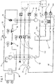
- Fig.1 shows a schematic view of an inventive arrangement for heat exchange and / or for temperature control of machine components 38, such as motor, ejector or clamping unit, an injection molding machine for processing plastics and other plasticizable materials such as ceramic and powdery Masses as a fluid circuit diagram with at least one secondary circuit 50, which is designed as a closed circuit with a cooling and / or tempering and at least one heat exchanger 16 and at least one pump 18 has. Via the heat exchanger 16, the secondary circuit 50 is cooled and / or tempered by at least one primary circuit 40. Furthermore, the arrangement according to Fig.
- a filling / emptying valve 36 is provided for first filling and / or emptying of the secondary circuit 50.
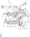
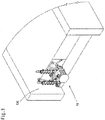
- the unit 10 can advantageously be reduced for cooling and refilling claimed installation space on the machine, so according to Fig. 3 the unit 10 can be attached to a base 100, for example an injection molding machine. This simultaneously centralizes the filling, maintenance and make-up of the primary and secondary circuits.
- At least one machine component 38 is at least one heat source - or heat sink - in the form of at least one further machine component 54 and / or in the form of another structural component 56 independently or partially independent of the secondary circuit 50 and optionally of the primary circuit 40 is temperature controlled, such as this in Fig. 1 is shown schematically on the top left.
- machine components 38, 54 can initially communicate thermally with one another across the machine by specifically using a heat influence of a machine component in order to influence the heat balance of another machine component.
- these other machine components via suitable coupling elements 58 such as heat exchangers, contact elements or additional heat circuits are coupled together in operative connection.
- the further structural component is connected via a decoupled from the primary circuit and / or secondary circuit, e.g. via a heat exchanger to a heat source or heat sink, such as a domestic heating circuit and / or underfloor heating and / or a heat pump, e.g. coupled to the building.
- the energy budget can be optimized or influenced by the machine from a suitable location, since heat sources and heat sinks can influence one another in a targeted manner. This applies both to internal machine heat sources and to external heat sources.
- Utilizing the waste heat of the machine components 38, 54 or a structural component 56 for temperature control of any machine component independently or partially independent of the primary circuit 40 and / or secondary circuit 50 has the advantage that the machine component does not have to be completely tempered "from zero to" the form that energy can be supplied to the machine component from any other machine component or structural component 56 and / or vice versa energy can be dissipated.
- the secondary circuit 50 at least one temperature sensor 44, which the temperature of the cooling and / or Temperiermediums detected and passes to at least one control unit 48, which influences at least one actuator 42, such as a valve, the primary circuit 40 takes.
- the temperature sensor 44 controls the control unit 48 via the actuator 42, for example, the temperature and / or the flow rate and thus the flow rate of the cooling and / or Temperiermediums in the primary circuit 40 so, for example, to a maximum 30 degrees Celsius and a maximum of 8 bar that the temperature in the secondary circuit 50 again assumes the desired value.
- the pressure in the primary circuit 40 can also be influenced via the actuator 42, that is to say increased or lowered in the context of pressure monitoring.
- the system separator 20 also influences the pressure in the secondary circuit 50 at the same time. A higher pressure in the primary circuit 40 thus leads to a higher pressure in the secondary circuit 50, whereby a larger amount of cooling and / or temperature control in the secondary circuit is available, which can thus also influence the temperature in the secondary circuit.
- the secondary circuit 50 preferably has at least one minimum pressure monitor 22 which, when the minimum pressure set, e.g. of 0.07 MPa, prevents damage to the device by switching off the machine and is designed, for example, as a membrane pressure switch.
- the minimum pressure set e.g. of 0.07 MPa
- the system separator 20 is preferably designed as a check valve.
- At least one filter element 14 is provided in the refill strand, which e.g. is designed as a dirt trap.
- Air is known to be a poor conductor of heat. Due to an excessive amount of air in the secondary circuit 50, the desired cooling and / or temperature control can be greatly influenced. Therefore, in the exemplary embodiment, the secondary circuit 50 at least one vent 26, for example, an automatic quick exhaust, can escape through the trapped air.
- the secondary circuit 50 also has at least one overpressure protection 24, which is designed for example as a pressure relief valve and, for example, opens at a pressure of 1.0 MPa and reduces pressure.
- the secondary circuit 50 has at least one further heat exchanger 16 for cooling and / or for temperature control of a further machine component 38, for example an oil tank 52.
- a further machine component 38 for example an oil tank 52.
- further heat exchangers 16 for further machine components 38 individual machine components 38 can be separated or independently or partially independent of Primary 40 and / or secondary circuit 50 via heat exchanger 16 couple together and temper.
- any machine component 38 can thus supply energy from another arbitrary machine component 38 and / or inversely dissipate energy, for example it is possible to use the waste heat of any machine component 38 for heating the oil container 52 and vice versa.
- the primary circuit 40 optionally has at least one volume flow measurement.
- the control unit 48 is connected on the one hand bidirectionally with the actuator 42, on the other hand, the control unit 48 is also connected to the minimum pressure monitor 22 in connection.
Landscapes
- Engineering & Computer Science (AREA)
- Manufacturing & Machinery (AREA)
- Mechanical Engineering (AREA)
- Physics & Mathematics (AREA)
- Health & Medical Sciences (AREA)
- Oral & Maxillofacial Surgery (AREA)
- Thermal Sciences (AREA)
- Injection Moulding Of Plastics Or The Like (AREA)
- Moulds For Moulding Plastics Or The Like (AREA)
Description
- Die Erfindung betrifft eine Anordnung zum Wärmeaustausch und/oder zur Temperierung von Maschinenkomponenten einer Spritzgießmaschine zur Verarbeitung von Kunststoffen und anderen plastifizierbaren Massen wie keramischen und pulverförmigen Massen nach dem Oberbegriff des Anspruches 1.
- Aus der dem Oberbegriff des Anspruches 1 zu Grunde liegenden
DE 25 51 423 A1 ist eine Einrichtung zum Heizen und/oder Kühlen von Hohlkörpern wie insbesondere von Formen bei der Kunststoffverarbeitung bekannt. Die Einrichtung weist einen Heiz- und Kühlkreislauf mit automatischer Nachspeisung auf, wobei die Nachspeisung des Kühlwassers in Abhängigkeit von Druck und Temperatur des Umlaufsystems über eine Heizung erfolgt, in der ein Druckminderer und ein Membranausgleichsgefäß angeordnet sind. Damit das Kühlmedium Wasser bei Temperaturen bis 130° C nicht siedet, wird eine Grundvorspannung von ca. 2.2 bar erzeugt, wobei die Volumen- / Druckschwankungen von dem Membranausgleichsgefäß aufgenommen werden. Der mittels Druckminderer auf 2.2 bar eingestellte Druck im Nachspeisestrang bleibt konstant, wobei der Druck im inneren Prozesskreislauf je nach Temperatur zwischen 2,2 bar und max. 6 bar schwanken kann. Der Einfluss eines Differenzdrucks wird nicht näher erläutert. Diese Einrichtung weist einen Wärmetauscher auf, wobei die Nachspeisung des Kühlmediums in Abhängigkeit von Druck und Temperatur automatisch erfolgt. Mit Hilfe der Druckminderungseinrichtung und des Membranausgleichsgefäßes kann mit der Einrichtung bei einem niedrigen Atmosphärendruck gearbeitet werden, wobei eine Funktionssicherheit auch bei Temperaturen über 100 Grad Celsius gewährleistet ist. Eine Nutzung der Abwärme zur Temperierung von Maschinenkomponenten ist nicht offenbart, dort wird das geschlossene Umlaufsystem lediglich mit Hilfe des Kühlwassers entweder gekühlt oder beheizt, wobei das Umlaufmedium nicht mit dem Kühlwasser in Berührung kommt. - Aus der
DE 20 2009 003 331 U1 ist ein weiteres Kühlsystem für ein Werkzeug einer Spritzgießmaschine bekannt. Das Kühlsystem weist einen Maschinenkreislauf, der durch das Werkzeug verläuft, einen Wasser/Luft-Wärmetauscher, eine Kältemaschine und eine Steuerung auf, wobei in Abhängigkeit der Außentemperatur die Kältemaschine dem Kühlsystem zugeschaltet wird, wenn über den Wasser/Luft-Wärmetauscher nicht genügend Energie abgegeben werden kann. Dadurch ergibt sich ein Kühlsystem, welches geringe Betriebskosten aufweist und die Vorlauftemperatur des Kühlmittels auf einem konstanten und niedrigen Wert hält. Aufgrund minimaler Leckagen im Kühlsystem kann es zu einem Druckabfall und bei Unterschreitung eines Minimaldruckes zu ungeplanten Stillstandzeiten des kompletten Werkzeugs kommen. - Die
DE 102 47 868 A1 offenbart ein Verfahren zur Abfuhr thermischer Energie aus einem Kaltwasserkreislauf mit einem wärmeerzeugenden Werkzeug und mit einer Lufttrocknung mit Wärmerückgewinnung. Um zu vermeiden, dass bei Prozessen, welche eine Kühlwassertemperatur unterhalb des Taupunktes benötigen, Feuchtigkeit an der Oberfläche von Werkzeugen kondensiert und somit erhebliche Produktionsstörungen verursacht, wird der Umgebungsluft Wärme entzogen und an den Kaltwasser- und Verdampferkreis abgegeben, wobei gleichzeitig die Verlustwärme zur Erhöhung der Lufttemperatur genutzt wird. - Die oben genannten Erfindungen offenbaren ein Kühlsystem bzw. einen Kühlkreislauf mit einem definierten Kühlmedium. Jedoch treten systembedingt in einem Kühlkreislauf Kühlmediumsverluste auf, die beispielsweise durch Verdunstung, durch Entlüftung der Anlage oder durch minimale Leckagen an Verbindungsstellen verursacht werden können. Diese Verluste führen früher oder später zu einer Verringerung des Systemdrucks bzw. zu einem Druckabfall und im schlimmsten Fall dazu, dass Luft angesaugt wird und in den Kühlkreislauf gelangt und es so zu ungeplanten Stillstandszeiten und/oder zu einer Schädigung der Anlage kommt.
- Die
US 3 748 866 A offenbart an einer Blasformmaschine einen Primärkreislauf und einen Sekundärkreislauf als auch eine Nachspeisung, aber keine Nutzung der Abwärme. - Die
DE 103 19 243 B3 offenbart zur Temperierung eines Spritgießwerkzeugs eine Nutzung von Abwärme zur zumindest teilweise unabhängigen Temperierung, jedoch nicht, dass eine Maschinekomponente durch Abwärme einer weiteren Maschinekomponente temperierbar ist. Stattdessen wird dort die Restwärme der Formkühlung wieder für die Formtemperierung verwendet. Eine Nachspeisung des Kühl- und/oder Temperiermediums ist nicht vorgesehen. - Aus der
DE 10 2008 025 557 A1 ist es bekannt, an einer Spritzgießmaschine Abwärme einer weiteren Maschinekomponente zur Temperierung eines Sekundärkreislaufs anzuwenden. Eine zumindest teilweise vom Primär und/oder Sekundärkreislauf unabhängige Temperierung ist nicht offenbart. - Die
DE 16 73 467 A1 zeigt an einer Formmaschine eine Nachspeisung aus einem ersten Strömungsmittelkreislauf in einen zweiten Strömungsmittelkreislauf, um Leckverluste gering zu halten. Die Strömungsmittelkreisläufe sind jedoch separiert und nicht mit einem Wärmetauscher zur Kühlung und/oder Temperierung verbunden. - Aus GRIES H: "HEISS UND KALT RICHTIG TEMPERIEREN TEIL 6", PLASTVERARBEI-TER, HUETHIG GMBH, HEIDELBERG, DE, Bd. 49, Nr. 9, 1. September 1999 (1999-09-01), XP000935458, ISSN: 0032-1338 wird zur Temperierung im Formenbau eine Nachspeisung bei einem Primärkreislauf und einem Sekundärkreislauf vorgeschlagen.
- Ausgehend von diesem Stand der Technik liegt der vorliegenden Erfindung die Aufgabe zugrunde, einen Wärmeaustausch und/oder eine Temperierung von Maschinenkomponenten sicher, effizient und zuverlässig zu gewährleisten.
- Diese Aufgabe wird mit einer Anordnung zum Wärmeaustausch und/oder zur Temperierung von Maschinenkomponenten gemäß den Merkmalen des Anspruchs 1 gelöst. Vorteilhafte Weiterbildungen sind Gegenstand der abhängigen Ansprüche. Die in den Ansprüchen einzeln aufgeführten Merkmale sind in technologisch sinnvoller Weise miteinander kombinierbar und können durch erläuternde Sachverhalte aus der Beschreibung und durch Details aus den Figuren ergänzt werden, wobei weitere Ausführungsvarianten der Erfindung aufgezeigt werden.
- Die Anordnung zum Wärmeaustausch und/oder zur Temperierung von Maschinenkomponenten einer Spritzgießmaschine weist wenigstens einen geschlossen Sekundärkreislauf mit einem Kühl- und/oder Temperiermedium, wenigstens einen Wärmetauscher und wenigstens eine Pumpe auf. Ferner weist die Anordnung wenigstens einen Primärkreislauf, der den Sekundärkreislauf über den Wärmetauscher kühlt und/oder temperiert, und wenigstens ein Aggregat auf, welches Anschlüsse für Kühl- und/oder Temperierleitungen zumindest des Primärkreislaufs, ggf. aber auch des Sekundärkreislaufs umfasst. Erfindungsgemäß sind wenigstens ein Systemtrenner zwischen Primär- und Sekundärkreislauf sowie wenigstens ein Nachfüllstrang vorgesehen, der mit dem Primarkreislauf in Fluidverbindung steht. Dabei erfolgt eine Nachspeisung und/oder ein Ausgleich des Kühl- und/oder Temperiermediums im Sekundärkreislauf mit Hilfe des Systemtrenners nur bei einem positiven Differenzdruck zwischen Primär- und Sekundärkreislauf über den Nachfüllstrang aus dem Primärkreislauf und damit keine Nachspeisung und/oder kein Ausgleich bei einem negativen Differenzdruck oder einem Differenzdruck von null zwischen Primär- und Sekundärkreislauf, wodurch sich ein Wärmeaustausch und/oder eine Temperierung der Maschinenkomponenten sicher, effizient und zuverlässig ergibt. Ist der Druck im Sekundärkreislauf kleiner als im Primärkreislauf, öffnet der Systemtrenner und es fließt Kühl- und/oder Temperiermedium von dem Primärkreislauf nach. Ist jedoch der Druck im Primärkreislauf kleiner als im Sekundärkreislauf, blockt der Systemtrenner, sodass es zu keiner Vermischung zwischen Primär- und Sekundärkreislauf kommt. Auf ein Ausgleichsgefäß kann dabei verzichtet werden und der Primärkreislauf wird mit dem Sekundärkreislauf über einen Systemtrenner verbunden. Über diese Verbindung wird in den systembedingten Druckgrenzen (bis max. 8 bar) ein Druckgleichgewicht in beiden Kreisläufen hergestellt und bei Bedarf kontinuierlich nachgespeist.
- Ferner sind einzelne Maschinenkomponenten unabhängig oder teilweise unabhängig vom Primär- und/oder Sekundärkreislauf miteinander gekoppelt, sodass die Abwärme wenigstens einer weiteren Maschinenkomponente unabhängig oder teilweise unabhängig vom Sekundärkreislauf und ggf. vom Primärkreislauf wenigstens eine Maschinenkomponente temperiert. Dadurch lässt sich Energie einsparen, da sich die Energie der Maschinenkomponenten in Form von Abwärme weiter nutzen lässt, um beispielsweise weitere Maschinenkomponenten zu temperieren. Es muss daher die Maschinenkomponente nicht komplett "von null auf" temperiert werden, sondern es kann die Abwärme von anderen Maschinenkomponenten benutzt werden, um die Maschinenkomponente auf die gewünschte Temperatur zu temperieren. Insofern kann von einer geeigneten Stelle aus der Energiehaushalt über die Maschine hinweg optimiert oder beeinflusst werden, da sich Wärmequellen und Wärmesenken gegenseitig gezielt beeinflussen können. Dabei ist auch eine Ankopplung an das Wärmemanagement im Umfeld der Maschine möglich, wie z.B. eine Ankopplung an das Gebäude oder eine andere bauliche Komponente.
- Vorzugsweise ist die weitere baulichen Komponente über einen vom Primärkreislauf und/oder Sekundärkreislauf entkoppelten Kreislauf z.B. über einen Wärmetauscher an eine Wärmequelle oder Wärmesenke wie einen Hausheizungskreislauf und/oder eine Fußbodenheizung und/oder eine Wärmepumpe z.B. des Gebäudes gekoppelt.
- Vorteilhaft weist der Sekundärkreislauf wenigstens einen Temperaturfühler auf, welcher die Temperatur des Kühl- und/oder Temperiermediums erfasst und an wenigstens eine Regeleinheit übergibt, die Einfluss auf wenigstens ein Stellglied des Primärkreislaufs nimmt, sodass bei einer abweichenden Temperatur des Kühl- und/oder Temperiermediums im Sekundärkreislauf Parameter, wie z.B. die Temperatur und/oder die Fließgeschwindigkeit und damit auch die Durchflussmenge des Kühl- und/oder Temperiermediums im Primärkreislauf entsprechend angepasst werden können.
- Um Beschädigungen der Maschine und/oder Stillstandzeiten als Folge einer Unterschreitung des Minimaldrucks zu verhindern, weist der Sekundärkreislauf vorteilhaft wenigstens eine Minimaldrucküberwachung auf.
- Für eine einfache, sichere und kostengünstige Nachspeisung und/oder Ausgleichung des Sekundärkreislauf mit dem Kühl- und/oder Temperiermedium ist der Systemtrenner als ein Rückschlagventil ausgeführt ist. Prinzipiell denkbar sind aber auch andere Bauteile, die eine Nachspeisung und/oder Ausgleichung des Sekundärkreislaufs nur bei positivem Differenzdruck, sowie gleichzeitig keine Vermischung bei negativem Differenzdruck bzw. einem Differenzdruck von null bewirken.
- Um die zu kühlenden und/oder zu temperierenden Maschinenkomponenten vor Korrosion und Verschmutzung zu schützen weist der Nachfüllstrang vorteilhaft wenigstens ein Filterelement auf. Weiterhin wird dadurch verhindert, dass durch Schmutz und/oder Ablagerungen der Sekundärkreislauf verstopft und somit eine entsprechende Kühlung und/oder Temperierung nicht mehr gewährleistet ist.
- Luft ist im Allgemeinen ein sehr schlechter Wärmeleiter bzw. Wärmetauscher. Im Falle einer ungenügenden Kühlung und/oder Temperierung im Sekundärkreislauf aufgrund von eingeschlossener Luft weist der Sekundärkreislauf vorteilhaft wenigstens einen Entlüfter auf, wodurch die Luft automatisch entweichen kann und so ein besserer Wärmeaustausch mittels des Kühl- und/oder des Temperiermediums erfolgen kann.
- Vorzugsweise als Schutzeinrichtung des Sekundärkreislaufs gegenüber mechanischen Verformungen von Komponenten des Kreislaufs bei zu hohen Drücken weist der Sekundärkreislauf wenigstens eine Überdruckabsicherung auf. Dadurch wird zudem eine korrekte Funktion des Kreislaufs gewährleistet, da es bei hohen Drücken bzgl. der Zirkulation des Kühl- und/oder des Temperiermediums zu Problemen kommen kann.
- Zur Kühlung und/oder zur Temperierung einer weiteren Maschinenkomponente, vorzugsweise eines Ölbehälters, weist der Sekundärkreislauf in bevorzugter Weise wenigstens einen weiteren Wärmetauscher auf. Prinzipiell denkbar sind für den Betrieb des Wärmetauschers mit dem Ölbehälter z.B. drei Arbeitsbereiche. Im klassischen Fall wird die Abwärme aus dem Ölbehälter dem Sekundärkreislauf zugeführt und über den Primärkreislauf abgeführt. Weiterhin bzw. zusätzlich ist es möglich, die Abwärme weiterer angeschlossener Maschinenkomponenten, wie beispielsweise Servomotoren und/oder Wechselrichter, aus dem Sekundärkreis über den Wärmetauscher dem Öl im Ölbehälter zuzuführen und so das Öl vorzuwärmen. Auch kann die Abwärme des Öls benutzt werden, um weitere Maschinenkomponenten aus dem Sekundärkreis zu temperieren. Die drei verschiedenen Möglichkeiten können ebenfalls in beliebiger Form miteinander kombiniert werden.
- Im Falle von größeren Leckagen im Sekundärkreislauf weist der Primärkreislauf vorteilhaft wenigstens eine Volumenstrommessung auf, sodass nachvollzogen werden kann, wieviel Kühl- und/oder Temperiermedium verloren wurde bzw. wie groß in etwa das Leck ist.
- Im Folgenden wird die Erfindung anhand eines in den beigefügten Figuren dargestellten Ausführungsbeispiels näher erläutert. Es zeigen:
- Fig. 1
- eine schematische Ansicht der erfindungsgemäßen Anordnung als Fluidschalt-plan,
- Fig. 2
- eine perspektivische Ansicht von schräg oben eines Aggregats,
- Fig. 3
- eine perspektivische Ansicht von schräg oben eines Standfußes einer Spritzgießmaschine mit dem Aggregat gemäß
Fig. 2 . - Die Erfindung wird jetzt beispielhaft unter Bezug auf die beigefügten Zeichnungen näher erläutert. Allerdings handelt es sich bei den Ausführungsbeispielen nur um Beispiele, die nicht das erfinderische Konzept auf eine bestimmte Anordnung beschränken sollen. Bevor die Erfindung im Detail beschrieben wird, ist darauf hinzuweisen, dass sie nicht auf die jeweiligen Bauteile der Vorrichtung sowie die jeweiligen Verfahrensschritte beschränkt ist, da diese Bauteile und Verfahren variieren können. Die hier verwendeten Begriffe sind lediglich dafür bestimmt, besondere Ausführungsformen zu beschreiben und werden nicht einschränkend verwendet. Wenn zudem in der Beschreibung oder in den Ansprüchen die Einzahl oder unbestimmte Artikel verwendet werden, bezieht sich dies auch auf die Mehrzahl dieser Elemente, solange nicht der Gesamtzusammenhang eindeutig etwas Anderes deutlich macht.
-
Fig.1 zeigt eine schematische Ansicht einer erfindungsgemäßen Anordnung zum Wärmeaustausch und/oder zur Temperierung von Maschinenkomponenten 38, wie beispielweise Motor, Auswerfer oder Schließeinheit, einer Spritzgießmaschine zur Verarbeitung von Kunststoffen und anderen plastifizierbaren Massen wie keramischen und pulverförmigen Massen als Fluidschaltplan mit wenigstens einem Sekundärkreislauf 50, welcher als geschlossener Kreislauf mit einem Kühl- und/oder Temperiermedium ausgeführt ist und wenigstens einen Wärmetauscher 16 und wenigstens eine Pumpe 18 aufweist. Über den Wärmetauscher 16 wird der Sekundärkreislauf 50 durch wenigstens einen Primärkreislauf 40 gekühlt und/oder temperiert. Weiterhin weist die Anordnung gemäßFig. 2 wenigstens ein Aggregat 10 auf, wobei das z.B. als Verteiler ausgebildete Aggregat 10 Anschlüsse 30 für Zu- 34a und/oder Abläufe 34b des Sekundärkreislaufs 50 und des Primärkreislaufs 40 aufweist. Zur Erstbefüllung und/oder zur Leerung des Sekundärkreislaufs 50 ist ein Befüllungs-/Entleerungsventil 36 vorgesehen. - Durch die kompakte Bauweise des Aggregats 10 kann vorteilhaft der für Kühlung und Nachspeisung beanspruchte Bauraum an der Maschine verkleinert werden, sodass gemäß
Fig. 3 das Aggregat 10 an einem Standfuß 100, z.B. einer Spritzgießmaschine angebracht werden kann. Damit wird gleichzeitig die Befüllung, Wartung und Nachspeisung der primär- und Sekundärkreisläufe zentralisiert. Über einen vom Primärkreislauf 40 abgezweigten Nachfüllstrang 46 und einen Systemtrenner 20 wird nur bei einem positiven Differenzdruck zwischen Primär- 40 und Sekundärkreislauf 50, beispielsweise bei einer Leckage, Kühl- und/oder Temperiermedium aus dem Primärkreislauf in den Sekundärkreislauf selbsttätig nachgespeist und/oder ausgeglichen, indem der Systemtrenner 20 in diesem Fall öffnet, während hingegen bei einem Differenzdruck kleiner gleich null der Systemtrenner 20 schließt und so keine Vermischung des Sekundär- 50 mit dem Primärkreislauf 40 stattfinden kann, da dann auch keine Nachspeisung oder kein Ausgleich erforderlich ist. - Wenigstens eine Maschinenkomponente 38 ist durch die Abwärme wenigstens einer Wärmequelle - oder auch Wärmesenke - in Form wenigstens einer weiteren Maschinenkomponente 54 und/oder in Form einer weiteren baulichen Komponente 56 unabhängig oder teilweise unabhängig vom Sekundärkreislauf 50 und ggf. vom Primärkreislauf 40 temperierbar ist, wie dies in
Fig. 1 links oben schematisch dargestellt ist. Dadurch können zunächst über die Maschine hinweg Maschinenkomponenten 38, 54 miteinander thermisch kommunizieren, indem ein Wärmeeinfluss einer Maschinenkomponente gezielt genutzt werden kann, um den Wärmehaushalt einer anderen Maschinenkomponente zu beeinflussen. Dazu sind diese weiteren Maschinenkomponenten über geeignete Kopplungselemente 58 wie z.B. auch Wärmetauscher, Kontaktelemente oder auch zusätzliche Wärmekreisläufe miteinander in Wirkverbindung gekoppelt. - Zusätzlich besteht aber auch die Möglichkeit den Sekundärkreislauf 50, wie in
Fig. 1 für die weitere Maschinenkomponenten 54 und die bauliche Komponente 56 dargestellt, als auch den Primärkreislauf 40, wie zeichnerisch nicht dargestellt, thermisch nicht nur durch die weitere Maschinenkomponente 38 sondern ergänzend oder alternativ durch eine andere bauliche Komponente 56 thermisch zu beeinflussen. - Denkbar ist z.B. eine Ankopplung an das Wärmemanagement im Umfeld der Maschine, wie z.B. eine Ankopplung an das Gebäude oder eine andere bauliche Komponente. Vorzugsweise ist die weitere bauliche Komponente über einen vom Primärkreislauf und/oder Sekundärkreislauf entkoppelten Kreislauf z.B. über einen Wärmetauscher an eine Wärmequelle oder Wärmesenke wie einen Hausheizungskreislauf und/oder eine Fußbodenheizung und/oder eine Wärmepumpe z.B. des Gebäudes gekoppelt.
- Insofern kann von einer geeigneten Stelle aus der Energiehaushalt über die Maschine hinweg optimiert oder beeinflusst werden, da sich Wärmequellen und Wärmesenken gegenseitig gezielt beeinflussen können. Dies gilt dabei sowohl für maschineninterne Wärmequellen als auch für maschinenexterne Wärmequellen.
- Denkbar ist z.B. eine Temperierung von Maschinenkomponenten mittels Abwärme von Maschinenkomponenten, welche nicht im Primär- und/oder Sekundärkreislauf angeordnet sind. Es ist aber auch denkbar, dass z.B. die mittels Abwärme temperierte Maschinenkomponente im Primär- und/oder Sekundärkreislauf angeordnet ist. Die Temperierung der Maschinenkomponente durch die Abwärme einer anderen Maschinenkomponente erfolgt somit zusätzlich zu einer eventuellen Temperierung der Maschinenkomponente durch den Primär- und/oder Sekundärkreislauf.
- Eine Nutzung der Abwärme der Maschinenkomponenten 38, 54 oder einer baulichen Komponente 56 zur Temperierung von einer beliebigen Maschinenkomponente unabhängig oder teilweise unabhängig vom Primärkreislauf 40 und/oder Sekundärkreislauf 50 hat den Vorteil, dass die Maschinenkomponente nicht komplett "von null auf" temperiert werden muss in der Form, dass der Maschinenkomponente Energie von einer anderen beliebigen Maschinenkomponente oder baulichen Komponente 56 zugeführt und/oder umgekehrt Energie abgeführt werden kann.
- In einem bevorzugten Ausführungsbeispiel gemäß
Fig. 1 weist der Sekundärkreislauf 50 wenigstens einen Temperaturfühler 44 auf, welcher die Temperatur des Kühl- und/oder Temperiermediums erfasst und an wenigstens eine Regeleinheit 48 übergibt, welche Einfluss auf wenigstens ein Stellglied 42, z.B. ein Ventil, des Primärkreislaufs 40 nimmt. Je nach ermittelter Temperatur, z.B. ab maximal 40 Grad Celsius, des Temperaturfühlers 44 regelt die Regeleinheit 48 über das Stellglied 42 beispielsweise die Temperatur und/oder die Fließgeschwindigkeit und damit die Durchflussmenge des Kühl- und/oder Temperiermediums im Primärkreislauf 40 so, beispielweise auf maximal 30 Grad Celsius bzw. maximal 8 bar, dass die Temperatur im Sekundärkreislauf 50 wieder den gewünschten Wert einnimmt. - Grundsätzlich kann über das Stellglied 42 auch der Druck im Primärkreislauf 40 beeinflusst, also im Rahmen der Drucküberwachung erhöht oder abgesenkt werden. Über den Systemtrenner 20 wird damit gleichzeitig auch der Druck im Sekundärkreislauf 50 beeinflusst. Ein höherer Druck im Primärkreislauf 40 führt damit zu einem höheren Druck im Sekundärkreislauf 50, wodurch eine größere Menge an Kühl- und/oder Temperiermedium im Sekundärkreislauf zur Verfügung steht, was damit auch die Temperatur im Sekundärkreislauf beeinflussen kann.
- Der Sekundärkreislauf 50 weist bevorzugt wenigstens eine Minimaldrucküberwachung 22 auf, welche bei einer Unterschreitung des eingestellten Minimaldrucks, z.B. von 0,07 MPa, eine Schädigung der Einrichtung durch Abschalten der Maschine verhindert und beispielsweise als ein Membran-Druckschalter ausgeführt ist.
- Für eine einfache, sichere und kostengünstige Trennung von Primär- 40 und Sekundärkreislauf 50 ist der Systemtrenner 20 vorzugsweise als ein Rückschlagventil ausgeführt.
- Bevorzugt zum Schutz vor Korrosion und Verschmutzung durch eine Nachspeisung über den Nachfüllstrang 46 ist im Nachfüllstrang wenigstens ein Filterelement 14 vorgesehen, welches z.B. als ein Schmutzfänger ausgeführt ist.
- Luft ist bekanntlich ein schlechter Wärmeleiter. Durch einen zu hohen Anteil an Luft im Sekundärkreislauf 50 kann die gewünschte Kühl- und/oder Temperierleistung stark beeinflusst werden. Daher weist im Ausführungsbeispiel der Sekundärkreislauf 50 wenigstens einen Entlüfter 26 auf, beispielsweise einen automatischen Schnellentlüfter, über den eventuell eingeschlossene Luft entweichen kann.
- Zum Schutz vor einer Beschädigung des Sekundärkreislaufs 50 und/oder der Maschinenkomponenten 38 weist der Sekundärkreislauf 50 ferner wenigstens eine Überdruckabsicherung 24 auf, welche z.B. als ein Überdruckventil ausgeführt ist und beispielsweise bei einem Druck von 1,0 MPa öffnet und Druck abbaut.
- Im Ausführungsbeispiel weist der Sekundärkreislauf 50 wenigstens einen weiteren Wärmetauscher 16 zur Kühlung und/oder zur Temperierung einer weiteren Maschinenkomponente 38 auf, beispielsweise eines Ölbehälters 52. Über weitere Wärmetauscher 16 für weitere Maschinenkomponenten 38 lassen sich einzelne Maschinenkomponenten 38 getrennt bzw. unabhängig oder teilweise unabhängig vom Primär- 40 und/oder Sekundärkreislauf 50 über Wärmetauscher 16 miteinander koppeln und temperieren. Prinzipiell lässt sich so einer beliebigen Maschinenkomponente 38 Energie von einer anderen beliebigen Maschinenkomponente 38 zuführen und/oder umgekehrt Energie abführen, beispielsweise ist es möglich, die Abwärme einer beliebigen Maschinenkomponente 38 zum Anwärmen des Ölbehälters 52 zu verwenden und umgekehrt. Denkbar ist auch eine Kopplung des Sekundärkreislaufs 50 und/oder eines beliebigen, vom Primärkreislauf 40 und/oder Sekundärkreislauf 50 entkoppelten Kreislaufs über einen Wärmetauscher 16 an beispielsweise einen Hausheizungskreislauf und/oder eine Fußbodenheizung.
- Zur Trennung der Nachspeisung vom Primärkreislauf 40 bei größeren Leckagen im Sekundärkreislauf 50 weist der Primärkreislauf 40 ggf. wenigstens eine Volumenstrommessung auf. Hierzu ist die Regeleinheit 48 einerseits mit dem Stellglied 42 bidirektional verbunden, andererseits steht die Regeleinheit 48 auch mit der Minimaldrucküberwachung 22 in Verbindung.
-
- 10
- Aggregat
- 12
- Sperrventil
- 14
- Filterelement
- 16
- Wärmetauscher
- 18
- Pumpe
- 20
- Systemtrenner
- 22
- Minimaldrucküberwachung
- 24
- Überdruckabsicherung
- 26
- Entlüfter
- 28
- Temperatursensor
- 30
- Anschlüsse
- 32
- Manometer
- 34a
- Zulauf (kalt)
- 34b
- Ablauf (warm)
- 36
- Befüllungs-/Entleerungsventil
- 38
- Maschinenkomponente
- 40
- Primärkreislauf
- 42
- Stellglied
- 44
- Temperaturfühler
- 46
- Nachfüllstrang
- 48
- Regeleinheit
- 50
- Sekundärkreislauf
- 52
- Ölbehälter
- 54
- weitere Maschinenkomponente
- 56
- bauliche Komponente
- 58
- Koppelelement
- 100
- Standfuß
Claims (10)
- Anordnung zum Wärmeaustausch und/oder zur Temperierung von Maschinenkomponenten (38) einer Spritzgießmaschine zur Verarbeitung von Kunststoffen und anderen plastifizierbaren Massen wie keramischen und pulverförmigen Massen mit- wenigstens einem Sekundärkreislauf (50), der ein geschlossener Kreislauf mit einem Kühl- und/oder Temperiermedium ist und wenigstens einen Wärmetauscher (16) und wenigstens eine Pumpe (18) aufweist,- wenigstens einem Primärkreislauf (40), der den Sekundärkreislauf (50) über den Wärmetauscher (16) kühlt und/oder temperiert,- wenigstens einer Maschinenkomponente, die an den Primär- und/oder Sekundärkreislauf gekoppelt ist,- wenigstens einem Aggregat (10), wobei das Aggregat (10) Anschlüsse für Zu- und/oder Abläufe (34a, 34b; 30) des Primärkreislaufs (40) aufweist,- wenigstens einem Systemtrenner (20) zwischen Primärkreislauf (40) und Sekundärkreislauf (50),- wenigstens einem Nachfüllstrang (46), der mit dem Primärkreislauf (40) in Fluidverbindung steht,- wobei eine Nachspeisung und/oder ein Ausgleich des Kühl- und/oder Temperiermediums im Sekundärkreislauf (50) mit Hilfe des Systemtrenners (20) bei einem positiven Differenzdruck zwischen Primärkreislauf (40) und Sekundärkreislauf (50) über den Nachfüllstrang (46) aus den Primärkreislauf (40) erfolgt,dadurch gekennzeichnet, dass eine Nachspeisung und/oder ein Ausgleich nur bei einem positiven Differenzdruck zwischen Primär- (40) und Sekundärkreislauf (50) erfolgt und dass die wenigstens eine Maschinenkomponente (38) durch Abwärme wenigstens einer Wärmequelle in Form wenigstens einer weiteren Maschinenkomponente (54) und/oder in Form einer weiteren baulichen Komponente (56) unabhängig oder teilweise unabhängig vom Sekundärkreislauf (50) und ggf. im Primärkreislauf (40) temperierbar ist.
- Anordnung nach Anspruch 1, dadurch gekennzeichnet, dass die weitere bauliche Komponente (56) über einen vom Primärkreislauf (40) und/oder Sekundärkreislauf (50) entkoppelten Kreislauf über einen Wärmetauscher (16) an eine Wärmequelle oder Wärmesenke wie einen Hausheizungskreislauf und/oder eine Fußbodenheizung gekoppelt ist.
- Anordnung nach Anspruch 1 oder 2, dadurch gekennzeichnet, dass wenigstens eine Regeleinheit (48) vorgesehen ist und dass der Sekundärkreislauf (50) wenigstens einen Temperaturfühler (44) aufweist, welcher die Temperatur des Kühl- und/oder Temperiermediums erfasst und an die wenigstens eine Regeleinheit (48) übergibt, welche Einfluss auf wenigstens das Stellglied (42) des Primärkreislaufs (40) nimmt.
- Anordnung nach einem der vorhergehenden Ansprüche, dadurch gekennzeichnet, dass der Sekundärkreislauf (50) wenigstens eine Minimaldrucküberwachung (22) aufweist.
- Anordnung nach einem der vorhergehenden Ansprüche, dadurch gekennzeichnet, dass der Systemtrenner (20) als ein Rückschlagventil ausgeführt ist.
- Anordnung nach einem der vorhergehenden Ansprüche, dadurch gekennzeichnet, dass der Nachfüllstrang (46) wenigstens ein Filterelement (14) aufweist.
- Anordnung nach einem der vorhergehenden Ansprüche, dadurch gekennzeichnet, dass der Sekundärkreislauf (50) wenigstens einen Entlüfter (26) aufweist.
- Anordnung nach einem der vorhergehenden Ansprüche, dadurch gekennzeichnet, dass der Sekundärkreislauf (50) wenigstens eine Überdruckabsicherung (24) aufweist.
- Anordnung nach einem der vorhergehenden Ansprüche, dadurch gekennzeichnet, dass der Sekundärkreislauf (50) wenigstens einen weiteren Wärmetauscher (16) aufweist, über den die weitere Maschinenkomponente (38, 54), vorzugsweise ein Ölbehälter (52), temperierbar ist, oder dass die weitere Maschinenkomponente (38), vorzugsweise über den weiteren Wärmetauscher (16) den Sekundärkreislauf temperiert.
- Anordnung nach einem der vorhergehenden Ansprüche, dadurch gekennzeichnet, dass der Primärkreislauf (40) wenigstens eine Volumenstrommessung aufweist.
Applications Claiming Priority (1)
| Application Number | Priority Date | Filing Date | Title |
|---|---|---|---|
| DE102016119843.9A DE102016119843A1 (de) | 2016-10-18 | 2016-10-18 | Anordnung zum Wärmeaustausch und/oder zur Temperierung von Maschinenkomponenten |
Publications (2)
| Publication Number | Publication Date |
|---|---|
| EP3311974A1 EP3311974A1 (de) | 2018-04-25 |
| EP3311974B1 true EP3311974B1 (de) | 2019-08-07 |
Family
ID=60143530
Family Applications (1)
| Application Number | Title | Priority Date | Filing Date |
|---|---|---|---|
| EP17196840.7A Active EP3311974B1 (de) | 2016-10-18 | 2017-10-17 | Anordnung zum wärmeaustausch und/oder zur temperierung von maschinenkomponenten |
Country Status (2)
| Country | Link |
|---|---|
| EP (1) | EP3311974B1 (de) |
| DE (1) | DE102016119843A1 (de) |
Family Cites Families (6)
| Publication number | Priority date | Publication date | Assignee | Title |
|---|---|---|---|---|
| US3748866A (en) * | 1971-04-23 | 1973-07-31 | Owens Illinois Inc | Method and apparatus for chilling mold elements |
| DE2551423C3 (de) * | 1975-11-15 | 1978-11-02 | Voetsch Gmbh, 6450 Hanau | Einrichtung zum Heizen und/oder Kühlen von Hohlkörpern |
| DE10247868A1 (de) | 2002-10-14 | 2004-04-22 | gwk Gesellschaft Wärme Kältetechnik mbH | Verfahren zur Abfuhr thermischer Energie aus einem Kaltwasserkreislauf mit einem wärmeerzeugenden Werkzeug und Lufttrocknung mit Wärmerückgewinnung |
| DE10319243B3 (de) * | 2003-04-28 | 2004-08-19 | Technotrans Ag | Zufuhrvorrichtung für ein Temperiermittel zur Versorgung von Temperiermittelkanälen |
| DE102008025557B4 (de) * | 2008-05-28 | 2010-04-08 | gwk Gesellschaft Wärme Kältetechnik mbH | Spritzgießmaschine |
| DE202009003331U1 (de) | 2009-03-10 | 2009-06-18 | Oag Objekt- Und Anlagenplanungsgesellschaft Mbh | Kühlsystem für das Werkzeug einer Spritzgussmaschine |
-
2016
- 2016-10-18 DE DE102016119843.9A patent/DE102016119843A1/de not_active Withdrawn
-
2017
- 2017-10-17 EP EP17196840.7A patent/EP3311974B1/de active Active
Non-Patent Citations (1)
| Title |
|---|
| None * |
Also Published As
| Publication number | Publication date |
|---|---|
| EP3311974A1 (de) | 2018-04-25 |
| DE102016119843A1 (de) | 2018-04-19 |
Similar Documents
| Publication | Publication Date | Title |
|---|---|---|
| DE69924505T2 (de) | Verfahren und gerät zur kontrolle der temperatur | |
| EP3661720B1 (de) | Verfahren zur variothermen temperierung von spritzgiesswerkzeugen | |
| EP2208606B1 (de) | Streckblasmaschine mit beheizbarer Blasform und Verfahren zu deren Temperierung | |
| DE112015005248T5 (de) | Wärmebehandlungsvorrichtung und kühlvorrichtung | |
| EP1114971A2 (de) | Kühleinrichtung | |
| AT516167B1 (de) | Temperiervorrichtung zum variothermen oder konventionellen Temperieren von Formwerkzeugen | |
| DE2713339A1 (de) | Abkuehlsystem fuer formen | |
| EP2804737B1 (de) | Hydraulikeinrichtung mit einer temperiereinrichtung | |
| DE102014001563B4 (de) | Gussform | |
| EP2199058A1 (de) | Verfahren zur zyklusabhängigen Temperierung eines Spritzgieß- oder Thermoformwerkzeuges | |
| DE102010062260A1 (de) | Temperierbares Formwerkzeugelement | |
| DE102014102655A1 (de) | Verfahren und Vorrichtung zur Rückführung von Schwaden mit gleichzeitiger Rückgewinnung von Wärmeenergie | |
| DE202013104810U1 (de) | Vorrichtung zur variothermen Temperierung eines Spritzgießwerkzeugs | |
| EP3311974A1 (de) | Anordnung zum wärmeaustausch und/oder zur temperierung von maschinenkomponenten | |
| DE4104152C2 (de) | ||
| WO2001019590A1 (de) | Verfahren und vorrichtung zum temperieren von formwerkzeugen von spritzgussmaschinen | |
| DE2551423C3 (de) | Einrichtung zum Heizen und/oder Kühlen von Hohlkörpern | |
| EP3827209B1 (de) | Verfahren und vorrichtung zum kühlen eines werkzeugs | |
| EP2899007A1 (de) | Spritzguss-Werkzeug und Gießanlage mit dem Spritzguss-Werkzeug | |
| DE202006020117U1 (de) | Vorrichtung zur Temperierung eines Formwerkzeuges zur Herstellung von Formlingen aus Kunststoff oder Metall | |
| AT516700B1 (de) | Anordnung aus wenigstens einem Schneid- oder Bohrwerkzeug, insbesondere Diamantwerkzeug, für die Betonbearbeitung und wenigstens einer Kühleinheit | |
| EP4249138B1 (de) | Verfahren und vorrichtung zum reinigen einer anlagenkomponente in einer getränkebehandlungsanlage | |
| DE102010012456A1 (de) | Anlage zur Herstellung von Formteilen | |
| EP3309478B1 (de) | Verfahren zum betreiben eines kältekreislaufs | |
| DE2222137C3 (de) | Vorrichtung zur Kühlung einer Glasform |
Legal Events
| Date | Code | Title | Description |
|---|---|---|---|
| PUAI | Public reference made under article 153(3) epc to a published international application that has entered the european phase |
Free format text: ORIGINAL CODE: 0009012 |
|
| STAA | Information on the status of an ep patent application or granted ep patent |
Free format text: STATUS: THE APPLICATION HAS BEEN PUBLISHED |
|
| AK | Designated contracting states |
Kind code of ref document: A1 Designated state(s): AL AT BE BG CH CY CZ DE DK EE ES FI FR GB GR HR HU IE IS IT LI LT LU LV MC MK MT NL NO PL PT RO RS SE SI SK SM TR |
|
| AX | Request for extension of the european patent |
Extension state: BA ME |
|
| STAA | Information on the status of an ep patent application or granted ep patent |
Free format text: STATUS: REQUEST FOR EXAMINATION WAS MADE |
|
| 17P | Request for examination filed |
Effective date: 20181022 |
|
| RBV | Designated contracting states (corrected) |
Designated state(s): AL AT BE BG CH CY CZ DE DK EE ES FI FR GB GR HR HU IE IS IT LI LT LU LV MC MK MT NL NO PL PT RO RS SE SI SK SM TR |
|
| GRAP | Despatch of communication of intention to grant a patent |
Free format text: ORIGINAL CODE: EPIDOSNIGR1 |
|
| STAA | Information on the status of an ep patent application or granted ep patent |
Free format text: STATUS: GRANT OF PATENT IS INTENDED |
|
| RIC1 | Information provided on ipc code assigned before grant |
Ipc: B29C 35/00 20060101ALI20190212BHEP Ipc: B29C 45/73 20060101AFI20190212BHEP |
|
| INTG | Intention to grant announced |
Effective date: 20190225 |
|
| GRAS | Grant fee paid |
Free format text: ORIGINAL CODE: EPIDOSNIGR3 |
|
| GRAA | (expected) grant |
Free format text: ORIGINAL CODE: 0009210 |
|
| STAA | Information on the status of an ep patent application or granted ep patent |
Free format text: STATUS: THE PATENT HAS BEEN GRANTED |
|
| AK | Designated contracting states |
Kind code of ref document: B1 Designated state(s): AL AT BE BG CH CY CZ DE DK EE ES FI FR GB GR HR HU IE IS IT LI LT LU LV MC MK MT NL NO PL PT RO RS SE SI SK SM TR |
|
| REG | Reference to a national code |
Ref country code: GB Ref legal event code: FG4D Free format text: NOT ENGLISH |
|
| REG | Reference to a national code |
Ref country code: CH Ref legal event code: EP Ref country code: AT Ref legal event code: REF Ref document number: 1163145 Country of ref document: AT Kind code of ref document: T Effective date: 20190815 |
|
| REG | Reference to a national code |
Ref country code: DE Ref legal event code: R096 Ref document number: 502017001975 Country of ref document: DE |
|
| REG | Reference to a national code |
Ref country code: IE Ref legal event code: FG4D Free format text: LANGUAGE OF EP DOCUMENT: GERMAN |
|
| REG | Reference to a national code |
Ref country code: CH Ref legal event code: NV Representative=s name: MERVELIX SARL, CH |
|
| REG | Reference to a national code |
Ref country code: NL Ref legal event code: FP |
|
| REG | Reference to a national code |
Ref country code: LT Ref legal event code: MG4D |
|
| PG25 | Lapsed in a contracting state [announced via postgrant information from national office to epo] |
Ref country code: BG Free format text: LAPSE BECAUSE OF FAILURE TO SUBMIT A TRANSLATION OF THE DESCRIPTION OR TO PAY THE FEE WITHIN THE PRESCRIBED TIME-LIMIT Effective date: 20191107 Ref country code: NO Free format text: LAPSE BECAUSE OF FAILURE TO SUBMIT A TRANSLATION OF THE DESCRIPTION OR TO PAY THE FEE WITHIN THE PRESCRIBED TIME-LIMIT Effective date: 20191107 Ref country code: SE Free format text: LAPSE BECAUSE OF FAILURE TO SUBMIT A TRANSLATION OF THE DESCRIPTION OR TO PAY THE FEE WITHIN THE PRESCRIBED TIME-LIMIT Effective date: 20190807 Ref country code: PT Free format text: LAPSE BECAUSE OF FAILURE TO SUBMIT A TRANSLATION OF THE DESCRIPTION OR TO PAY THE FEE WITHIN THE PRESCRIBED TIME-LIMIT Effective date: 20191209 Ref country code: HR Free format text: LAPSE BECAUSE OF FAILURE TO SUBMIT A TRANSLATION OF THE DESCRIPTION OR TO PAY THE FEE WITHIN THE PRESCRIBED TIME-LIMIT Effective date: 20190807 Ref country code: LT Free format text: LAPSE BECAUSE OF FAILURE TO SUBMIT A TRANSLATION OF THE DESCRIPTION OR TO PAY THE FEE WITHIN THE PRESCRIBED TIME-LIMIT Effective date: 20190807 Ref country code: FI Free format text: LAPSE BECAUSE OF FAILURE TO SUBMIT A TRANSLATION OF THE DESCRIPTION OR TO PAY THE FEE WITHIN THE PRESCRIBED TIME-LIMIT Effective date: 20190807 |
|
| PG25 | Lapsed in a contracting state [announced via postgrant information from national office to epo] |
Ref country code: RS Free format text: LAPSE BECAUSE OF FAILURE TO SUBMIT A TRANSLATION OF THE DESCRIPTION OR TO PAY THE FEE WITHIN THE PRESCRIBED TIME-LIMIT Effective date: 20190807 Ref country code: GR Free format text: LAPSE BECAUSE OF FAILURE TO SUBMIT A TRANSLATION OF THE DESCRIPTION OR TO PAY THE FEE WITHIN THE PRESCRIBED TIME-LIMIT Effective date: 20191108 Ref country code: IS Free format text: LAPSE BECAUSE OF FAILURE TO SUBMIT A TRANSLATION OF THE DESCRIPTION OR TO PAY THE FEE WITHIN THE PRESCRIBED TIME-LIMIT Effective date: 20191207 Ref country code: AL Free format text: LAPSE BECAUSE OF FAILURE TO SUBMIT A TRANSLATION OF THE DESCRIPTION OR TO PAY THE FEE WITHIN THE PRESCRIBED TIME-LIMIT Effective date: 20190807 Ref country code: LV Free format text: LAPSE BECAUSE OF FAILURE TO SUBMIT A TRANSLATION OF THE DESCRIPTION OR TO PAY THE FEE WITHIN THE PRESCRIBED TIME-LIMIT Effective date: 20190807 |
|
| PG25 | Lapsed in a contracting state [announced via postgrant information from national office to epo] |
Ref country code: TR Free format text: LAPSE BECAUSE OF FAILURE TO SUBMIT A TRANSLATION OF THE DESCRIPTION OR TO PAY THE FEE WITHIN THE PRESCRIBED TIME-LIMIT Effective date: 20190807 |
|
| PG25 | Lapsed in a contracting state [announced via postgrant information from national office to epo] |
Ref country code: DK Free format text: LAPSE BECAUSE OF FAILURE TO SUBMIT A TRANSLATION OF THE DESCRIPTION OR TO PAY THE FEE WITHIN THE PRESCRIBED TIME-LIMIT Effective date: 20190807 Ref country code: EE Free format text: LAPSE BECAUSE OF FAILURE TO SUBMIT A TRANSLATION OF THE DESCRIPTION OR TO PAY THE FEE WITHIN THE PRESCRIBED TIME-LIMIT Effective date: 20190807 Ref country code: RO Free format text: LAPSE BECAUSE OF FAILURE TO SUBMIT A TRANSLATION OF THE DESCRIPTION OR TO PAY THE FEE WITHIN THE PRESCRIBED TIME-LIMIT Effective date: 20190807 Ref country code: PL Free format text: LAPSE BECAUSE OF FAILURE TO SUBMIT A TRANSLATION OF THE DESCRIPTION OR TO PAY THE FEE WITHIN THE PRESCRIBED TIME-LIMIT Effective date: 20190807 |
|
| PG25 | Lapsed in a contracting state [announced via postgrant information from national office to epo] |
Ref country code: MC Free format text: LAPSE BECAUSE OF FAILURE TO SUBMIT A TRANSLATION OF THE DESCRIPTION OR TO PAY THE FEE WITHIN THE PRESCRIBED TIME-LIMIT Effective date: 20190807 Ref country code: SK Free format text: LAPSE BECAUSE OF FAILURE TO SUBMIT A TRANSLATION OF THE DESCRIPTION OR TO PAY THE FEE WITHIN THE PRESCRIBED TIME-LIMIT Effective date: 20190807 Ref country code: CZ Free format text: LAPSE BECAUSE OF FAILURE TO SUBMIT A TRANSLATION OF THE DESCRIPTION OR TO PAY THE FEE WITHIN THE PRESCRIBED TIME-LIMIT Effective date: 20190807 Ref country code: IS Free format text: LAPSE BECAUSE OF FAILURE TO SUBMIT A TRANSLATION OF THE DESCRIPTION OR TO PAY THE FEE WITHIN THE PRESCRIBED TIME-LIMIT Effective date: 20200224 Ref country code: SM Free format text: LAPSE BECAUSE OF FAILURE TO SUBMIT A TRANSLATION OF THE DESCRIPTION OR TO PAY THE FEE WITHIN THE PRESCRIBED TIME-LIMIT Effective date: 20190807 |
|
| REG | Reference to a national code |
Ref country code: DE Ref legal event code: R097 Ref document number: 502017001975 Country of ref document: DE |
|
| PLBE | No opposition filed within time limit |
Free format text: ORIGINAL CODE: 0009261 |
|
| STAA | Information on the status of an ep patent application or granted ep patent |
Free format text: STATUS: NO OPPOSITION FILED WITHIN TIME LIMIT |
|
| PG2D | Information on lapse in contracting state deleted |
Ref country code: IS |
|
| PG25 | Lapsed in a contracting state [announced via postgrant information from national office to epo] |
Ref country code: LU Free format text: LAPSE BECAUSE OF NON-PAYMENT OF DUE FEES Effective date: 20191017 |
|
| 26N | No opposition filed |
Effective date: 20200603 |
|
| REG | Reference to a national code |
Ref country code: BE Ref legal event code: MM Effective date: 20191031 |
|
| PG25 | Lapsed in a contracting state [announced via postgrant information from national office to epo] |
Ref country code: SI Free format text: LAPSE BECAUSE OF FAILURE TO SUBMIT A TRANSLATION OF THE DESCRIPTION OR TO PAY THE FEE WITHIN THE PRESCRIBED TIME-LIMIT Effective date: 20190807 Ref country code: BE Free format text: LAPSE BECAUSE OF NON-PAYMENT OF DUE FEES Effective date: 20191031 |
|
| PG25 | Lapsed in a contracting state [announced via postgrant information from national office to epo] |
Ref country code: ES Free format text: LAPSE BECAUSE OF FAILURE TO SUBMIT A TRANSLATION OF THE DESCRIPTION OR TO PAY THE FEE WITHIN THE PRESCRIBED TIME-LIMIT Effective date: 20190807 Ref country code: IE Free format text: LAPSE BECAUSE OF NON-PAYMENT OF DUE FEES Effective date: 20191017 |
|
| PG25 | Lapsed in a contracting state [announced via postgrant information from national office to epo] |
Ref country code: CY Free format text: LAPSE BECAUSE OF FAILURE TO SUBMIT A TRANSLATION OF THE DESCRIPTION OR TO PAY THE FEE WITHIN THE PRESCRIBED TIME-LIMIT Effective date: 20190807 |
|
| PG25 | Lapsed in a contracting state [announced via postgrant information from national office to epo] |
Ref country code: MT Free format text: LAPSE BECAUSE OF FAILURE TO SUBMIT A TRANSLATION OF THE DESCRIPTION OR TO PAY THE FEE WITHIN THE PRESCRIBED TIME-LIMIT Effective date: 20190807 Ref country code: HU Free format text: LAPSE BECAUSE OF FAILURE TO SUBMIT A TRANSLATION OF THE DESCRIPTION OR TO PAY THE FEE WITHIN THE PRESCRIBED TIME-LIMIT; INVALID AB INITIO Effective date: 20171017 |
|
| GBPC | Gb: european patent ceased through non-payment of renewal fee |
Effective date: 20211017 |
|
| PG25 | Lapsed in a contracting state [announced via postgrant information from national office to epo] |
Ref country code: MK Free format text: LAPSE BECAUSE OF FAILURE TO SUBMIT A TRANSLATION OF THE DESCRIPTION OR TO PAY THE FEE WITHIN THE PRESCRIBED TIME-LIMIT Effective date: 20190807 |
|
| PG25 | Lapsed in a contracting state [announced via postgrant information from national office to epo] |
Ref country code: GB Free format text: LAPSE BECAUSE OF NON-PAYMENT OF DUE FEES Effective date: 20211017 |
|
| P01 | Opt-out of the competence of the unified patent court (upc) registered |
Effective date: 20230518 |
|
| PGFP | Annual fee paid to national office [announced via postgrant information from national office to epo] |
Ref country code: NL Payment date: 20241023 Year of fee payment: 8 |
|
| PGFP | Annual fee paid to national office [announced via postgrant information from national office to epo] |
Ref country code: DE Payment date: 20241010 Year of fee payment: 8 |
|
| PGFP | Annual fee paid to national office [announced via postgrant information from national office to epo] |
Ref country code: FR Payment date: 20241025 Year of fee payment: 8 Ref country code: AT Payment date: 20241021 Year of fee payment: 8 |
|
| PGFP | Annual fee paid to national office [announced via postgrant information from national office to epo] |
Ref country code: IT Payment date: 20241031 Year of fee payment: 8 |
|
| PGFP | Annual fee paid to national office [announced via postgrant information from national office to epo] |
Ref country code: CH Payment date: 20241101 Year of fee payment: 8 |